1. Introduction
Concrete-filled steel tubular (CFST) columns combine the tensile superiority of steel and the compressive advantage of concrete, delivering high-load-carrying capacity, large stiffness and excellent seismic ductility. Such members have been extensively employed in high-rise buildings, industrial plants and bridge substructures. In accordance with steel forming technology, square CFST columns are classified into square CFCFST columns and square CFTWST columns. The tailor-welded steel tube (CFTWST) referred to in this study is fabricated by welding four individual flat steel plates along their longitudinal edges to form a square hollow section. The welding process typically employs full-penetration butt welds using gas metal arc welding (GMAW) or submerged arc welding (SAW), depending on the plate thickness. The weld seams are located at the four corners of the square section. The heat-affected zones (HAZs) adjacent to the weld seams may exhibit altered material properties due to the thermal cycle, and welding residual stresses are generated as a result of localized heating and cooling. The residual stress distribution is characterized by tensile stresses near the weld seams and compressive stresses in the far-field regions. The weld quality and residual stress magnitude are influenced by welding parameters such as heat input, cooling rate, and post-weld treatment. B/t acts as a core index governing local buckling of steel tubes, which directly governs the composite interaction behavior, ultimate bearing capacity and post-yield deformation capacity of CFST members. An excessively large B/t triggers premature elastic local buckling of tube walls prior to steel yielding, severely impairing the composite synergistic effect between steel and infilled concrete.
To suppress local buckling, various calculation expressions for limiting
B/
t have been proposed in international design codes and academic investigations. Representative formulas cover the AISC360 [
1], Eurocode 4 [
2], GB 50936-2014 [
3], elastic buckling discriminant developed by Uy [
4], and simplified limit equation proposed by Guo [
5]. Nevertheless, most existing control criteria for
B/
t adopt a unified evaluation framework without differentiating material property discrepancies induced by cold forming and tailor welding processes. Cold-formed steel tubes exhibit prominent strain hardening during rolling, whereas welded tubes carry high-magnitude welding residual stress around weld seams. These two inherent characteristics alter the critical buckling state of tube walls, rendering uniform
B/
t limits inadequate for meeting the local stability requirements of the two column types. Indiscriminate application of identical limits in engineering practice either leads to overconservative cross-section design and material waste, or brings hidden risks of premature local buckling.
Existing research regarding the
B/
t of square CFST columns predominantly focuses on a single type of steel tube [
6,
7,
8], lacking comparative parametric analyses covering both CFCFST and CFTWST columns. Recent studies have further explored the buckling behavior of steel members using combined experimental and numerical approaches. Tahmasebinia et al. [
9] investigated the local buckling behavior of curved steel members through advanced finite element analysis, demonstrating the effectiveness of FE simulations in capturing complex buckling modes. Wang et al. [
10] conducted six experiments and parametric FE analysis on the lateral–torsional buckling of welded high-strength stainless steel I-girders, revealing that existing design codes cannot accurately predict the strength of such members. These findings highlight the need for fabrication-specific design provisions, which motivates the present comparative study on
B/
t limits for square CFST columns. Few studies systematically assess the applicable scopes, rationality and inherent defects of multiple code and academic formulas from the perspective of steel-concrete material compatibility mechanism, and differentiated limiting
B/
t systems tailored to cold forming and welding fabrication have not yet been established.
To address the above research gaps, the novelty of this study is threefold:
- (1)
Different focus from previous work: While the authors’ previous experimental and numerical study [
11] investigated the overall axial compressive performance (ultimate capacity, ductility, load–deformation responses, and DIC-based strain fields) of square CFCFST and CFTWST stub columns, the present work specifically targets the local buckling mechanism of tube walls and the steel–concrete compatibility mechanism, which were not addressed in [
11].
- (2)
Systematic comparison of design formulas: Unlike [
11], which focused on experimental observations and capacity prediction without assessing code provisions, this study critically evaluates five international design formulas (EC4, GB 50936, AISC 360, Uy, and Guo) under a unified FE framework, assessing their theoretical basis and applicability to both square CFCFST and CFTWST stub columns.
- (3)
Novel design recommendations: Most importantly, this study is the first to propose differentiated B/t limits for square CFCFST and CFTWST stub columns, based on the steel contribution ratio (θ = 45–55%)—a mechanistic criterion that goes beyond the empirical calibration of existing codes and provides direct quantitative guidance for cross-section optimization.
3. Analysis of Code Provisions and Classical Calculation Equations
The finite element (FE) approach adopted in this paper is consistent with the numerical framework reported in the authors’ previous study [
11]. The key modeling assumptions are summarized below.
Element types and mesh: The steel tube is modeled using 4-node shell elements with reduced integration (S4R), and the core concrete is modeled using 8-node solid elements (C3D8R). Following convergence studies, the mesh size is set to B/12 to B/10 where B is the cross-sectional width.
Material models: The steel adopts an elastic–plastic constitutive model with isotropic hardening. For CFCFST columns, the cold-forming effect is modeled by assigning zone-dependent material properties—corner regions are assigned enhanced yield strength based on the modification method proposed by Li et al. [
12], while flat regions retain the as-received strength. For CFTWST columns, welding residual stresses are incorporated following the idealized distribution pattern recommended in Han [
6], with tensile residual stresses concentrated near the weld seams and compressive residual stresses in the far-field regions. The concrete damaged plasticity (CDP) model in ABAQUS is adopted for the core concrete, with the stress–strain relationship proposed by Han [
6]. The CDP parameters were set as follows: dilation angle = 30°, eccentricity = 0.1, ratio of biaxial to uniaxial compressive strength = 1.16, and viscosity parameter = 0.0005, following the recommendations in [
6].
Boundary conditions and loading: Both ends are fixed against rotation and translation except for axial displacement at the loading end. A displacement-controlled monotonic loading protocol is applied.
Geometric imperfections: The first eigenmode from linear buckling analysis is introduced as the initial imperfection with an amplitude of L/1000, consistent with conventional engineering practice.
Interface interaction: The interface between the steel tube and core concrete is modeled as surface-to-surface contact with hard contact in the normal direction and a friction coefficient of 0.25 in the tangential direction.
The FE model was comprehensively validated in the authors’ previous study [
11] against: 14 in-house tests on square CFCFST and CFTWST stub columns under axial compression, covering concrete grades C30–C60, steel grades Q235–Q390, and wall thicknesses of 5, 8, and 12 mm. An independent experimental database compiled from the literature, comprising 210 specimens (163 CFTWST + 47 CFCFST) from over 30 published studies, covering
B/
t ratios from 12.5 to 120.8, steel strengths from 194 to 779 MPa, and concrete strengths from 12.3 to 164 MPa.
The validation included comparisons of ultimate bearing capacity, full load–displacement responses, transverse strain development, and local buckling failure modes. The statistical comparison between FE predictions and test results yielded mean NFE/Ntest ratios of 1.009 (σ = 0.056) for CFTWST and 1.003 (σ = 0.122) for CFCFST columns, confirming the reliability of the numerical framework.
All parametric cases in the present study are subsets of this validated parameter matrix—the steel grades (Q235–Q420), concrete grades (C30–C80), B/t ratios, and both tube types (CFCFST and CFTWST) are all within the ranges covered by the validation database. This ensures that the FE model reliably reflects the local buckling and composite mechanical performance of both CFCFST and CFTWST square CFST columns across the full range of parameters considered.
Specimens with a cross-section of 300 mm × 300 mm are adopted for parametric analysis in this study. Benefiting from the synergistic interaction between outer steel tube and core concrete, the ultimate bearing capacity of CFST members is higher than the simple superposition capacity of steel tube and concrete working alone. Nevertheless, once local buckling occurs to the outer steel tube before the member reaches its ultimate load-carrying capacity, the steel tube will lose effective confinement to the inner concrete, accompanied by a significant degradation of its own bearing capacity. In this case, the ultimate compressive capacity of the CFST specimen will be lower than the sum of individual bearing capacities of steel tube and concrete. Accordingly, the occurrence of premature local buckling of steel tubes can be effectively judged by comparing the actual ultimate capacity of CFST specimens with the superposed bearing capacity of two constituent materials.
Define the strength increase index
SI as the ratio of the ultimate bearing capacity of concrete-filled steel tube specimens to the sum of individual bearing capacities of the steel tube and core concrete, which can quantitatively identify premature local buckling of the outer steel tube:
where
Nue is the FE-predicted ultimate bearing capacity of the specimen;
Nuo is the theoretical superposed bearing capacity of the steel tube and core concrete,
Nuo =
Asfy +
Acfck,
As is cross-sectional area of the outer steel tube,
Ac is cross-sectional area of core concrete,
fck is characteristic compressive strength of concrete.
SI > 1 the steel tube does not buckle prior to the peak load, and the composite action is fully mobilized; SI < 1: the steel tube does buckle prior to the peak load, and the composite action is impaired; SI ≈ 1: the specimen is in a near-critical state.
It is important to acknowledge that the
SI index is an indirect indicator of local buckling. A reduction in
SI below unity does not uniquely prove that local buckling has occurred precisely before the peak load, as the loss of composite action may also be influenced by other factors, including concrete constitutive assumptions, confinement effectiveness, residual stresses, initial geometric imperfections, non-uniform yielding, and interface behavior. Nevertheless, from a practical engineering perspective,
SI serves as a conservative and consistent screening criterion for the following reasons. First, when the actual CFST capacity falls below the simple superposition of steel and concrete capacities, it indicates that the two materials are no longer working synergistically—which is the fundamental consequence of premature local buckling. Second, the
SI criterion has been widely adopted in previous CFST parametric studies for identifying local buckling thresholds (e.g., Han [
6]; Tao et al. [
7]), providing a well-established basis for its use. Third, and most importantly, the
SI criterion is applied uniformly across all parametric cases in this study; therefore, the comparative ranking of the five design formulas—which is the primary focus of this paper—remains valid regardless of potential deviations of the
SI indicator in absolute terms. In summary, while the
SI index is not a perfect physical measure of local buckling initiation, it provides a practical and conservative basis for parametric screening, and its use is justified for the purpose of comparing existing design provisions and establishing engineering-oriented
B/
t recommendations.
3.1. Parametric Trends and Governing Factors
Based on the
SI criterion defined in Equation (11), the parametric analysis across steel grades Q235–Q420, concrete grades C30–C80, and wall thicknesses corresponding to
B/
t ratios from 75 down to 30 reveals the following consistent trends. Detailed ultimate capacity data for individual cases are summarized in
Table 1,
Table 2,
Table 3 and
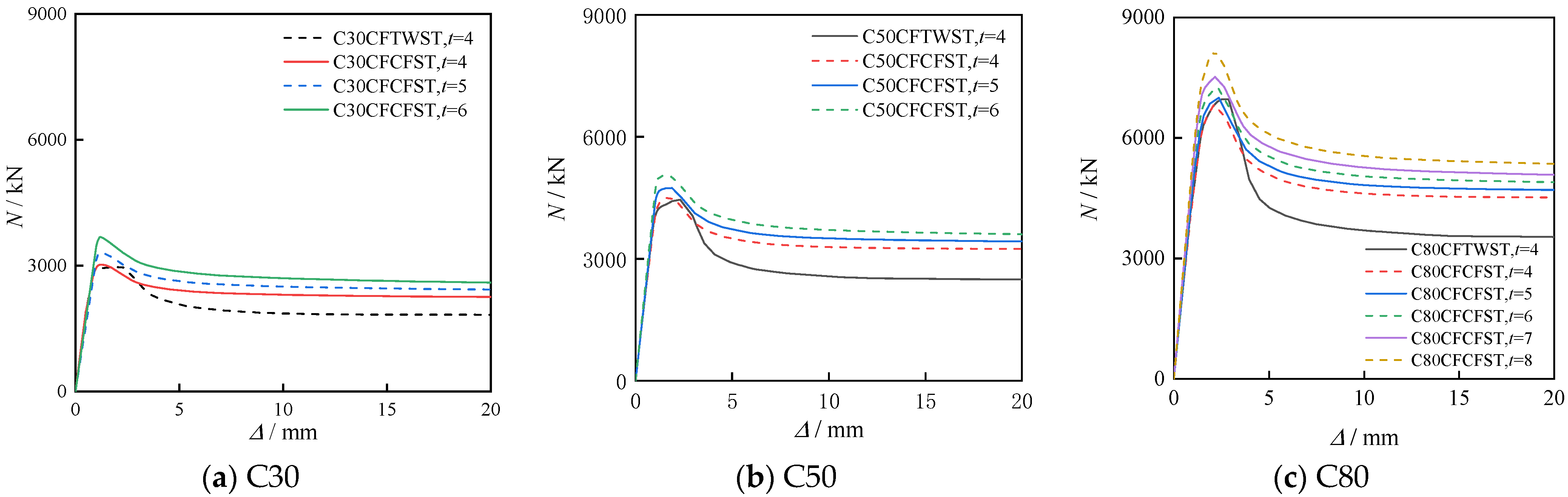
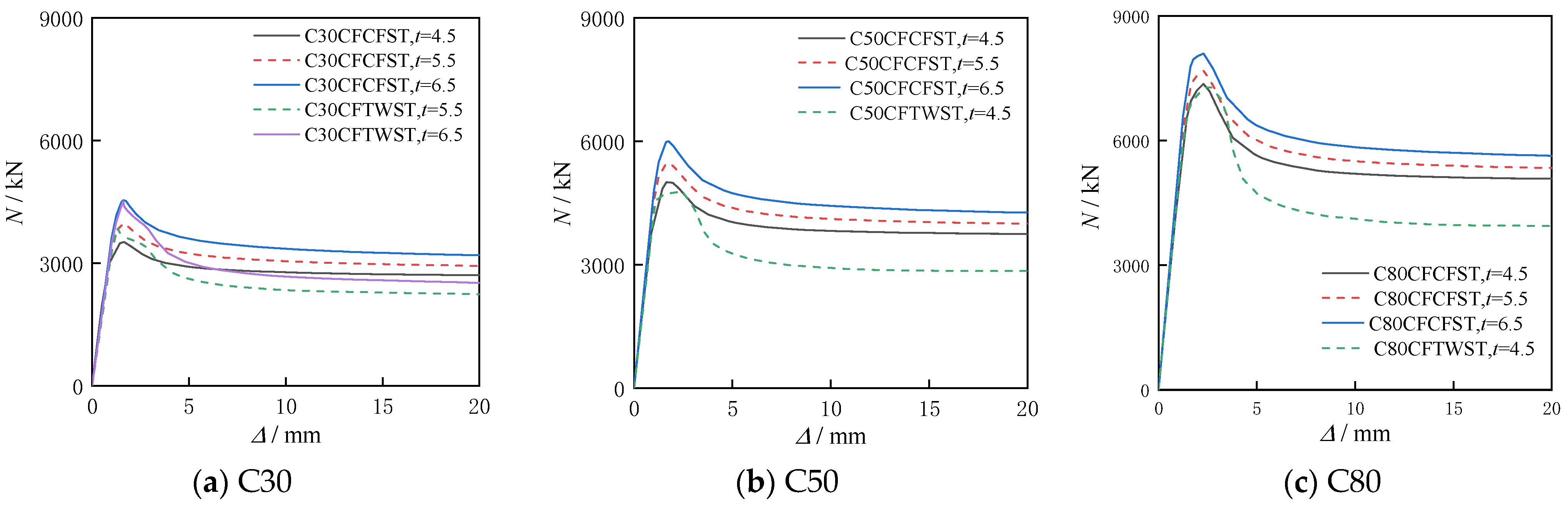
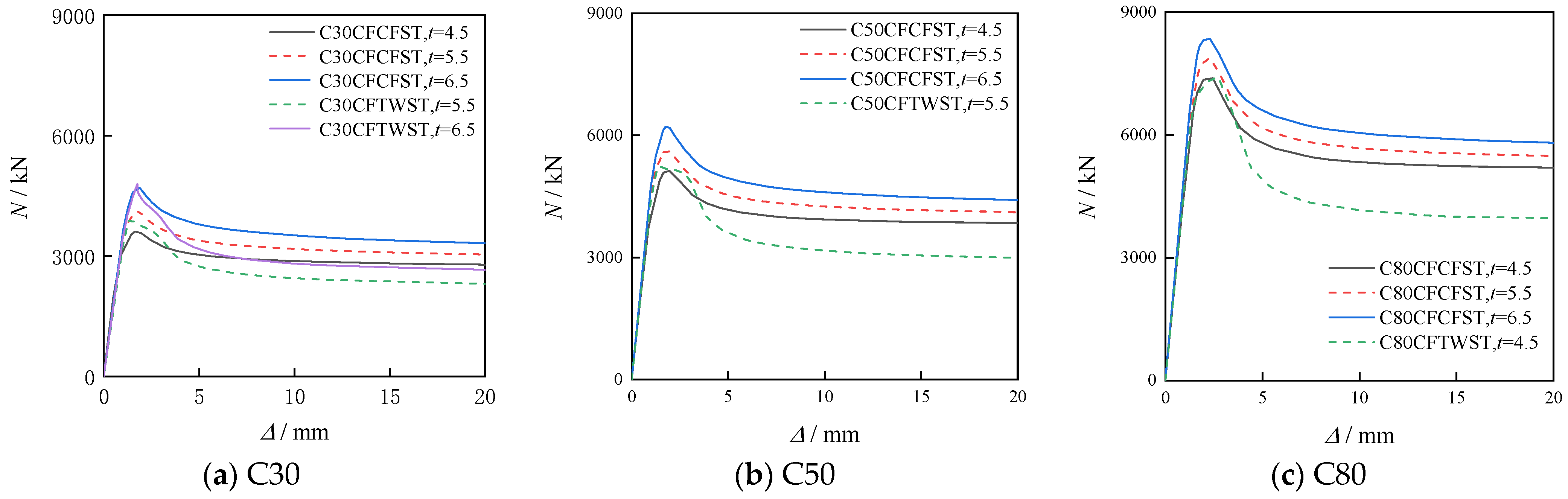
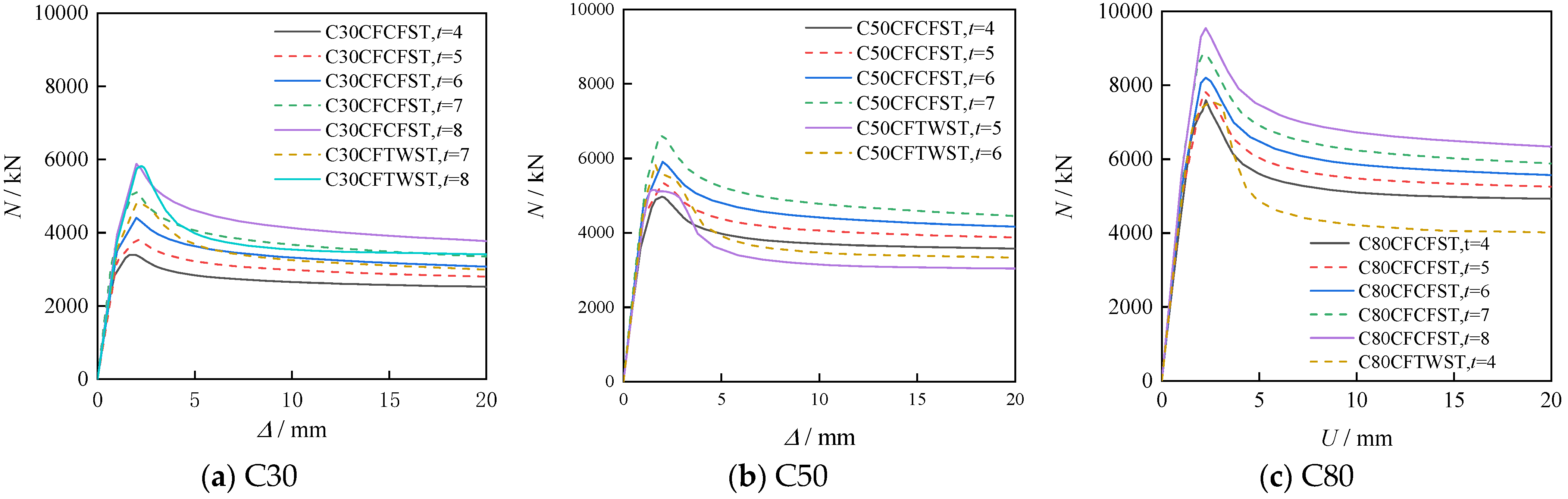
Table 4, and the corresponding load–deformation curves are shown in
Figure 1,
Figure 2,
Figure 3 and
Figure 4. In the following sections, the following notations are used:
B = outer width of the square cross-section;
t = wall thickness of the steel tube;
fy = yield strength of steel;
fcu,k = characteristic cube compressive strength of concrete.
3.1.1. Effect of Steel Grade
For a given concrete strength, the critical wall thickness required to avoid premature local buckling increases with steel yield strength. This is because higher-strength steel has a larger yield strain but a similar elastic modulus, making it more susceptible to elastic buckling under comparable deformation demands. For C30 concrete, for example, the critical wall thickness for CFTWST columns increases from 4 mm (Q235) to 6.5 mm (Q355) and further to 6.5 mm (Q390) and 8 mm (Q420). Consequently, design formulas with lower conservatism, such as Equation (6), tend to fail for high-strength steel grades combined with low-strength concrete.
This trend has important implications for design: when high-strength steel is used with low-strength concrete, the steel tube’s higher yield strength cannot be fully mobilized because the concrete provides insufficient axial stiffness and confinement to delay local buckling. The tube walls tend to buckle elastically before the steel reaches its yield stress, resulting in a brittle failure mode. Therefore, for such combinations, either thicker tube walls (smaller B/t) or the use of more conservative B/t limits is necessary to ensure adequate local stability.
3.1.2. Effect of Concrete Grade
Increasing the concrete strength grade reduces the critical wall thickness required to prevent premature local buckling. Higher-strength concrete carries a larger share of the axial load, thereby reducing the relative stress level in the steel tube and delaying its buckling. For Q355 CFTWST columns, for instance, the critical wall thickness decreases from 6.5 mm (C30) to 4.5 mm (C80). This trend is observed consistently across all steel grades and tube types.
The underlying mechanism is that high-strength concrete enhances the overall load-bearing capacity of the composite member while reducing the relative contribution of the steel tube to the total axial resistance. As a result, even if the steel tube experiences local buckling, its adverse effect on the ultimate capacity is mitigated because the concrete carries a dominant portion of the load. This explains why the minimum wall thickness requirement is less stringent for high-strength concrete. However, it should be noted that high-strength concrete also increases member brittleness, which may reduce post-peak ductility—a factor that should be considered in practical design.
3.1.3. Effect of B/t
For a given steel–concrete combination, specimens with smaller B/t (thicker walls) exhibit SI > 1, indicating stable behavior without premature local buckling. As B/t increases (walls become thinner), the SI value gradually decreases toward unity, beyond which local buckling occurs prior to the peak load. The exact threshold depends on the steel and concrete grades, but the general trend is consistent across all cases.
This trend can be explained by the fact that thicker tube walls provide greater flexural stiffness to the steel plates, increasing their resistance to out-of-plane deformation under axial compression. Moreover, thicker walls enable more effective confinement of the core concrete, enhancing the composite action and delaying the onset of local buckling. From a design perspective, the relationship between B/t and SI is approximately linear for practical ranges of B/t, which allows interpolation for intermediate values not explicitly covered in the parametric analysis.
3.1.4. Effect of Tube Forming Process
Under identical steel and concrete grades, the critical wall thicknesses triggering premature local buckling are essentially the same for CFCFST and CFTWST specimens (see
Table 1,
Table 2,
Table 3 and
Table 4 for detailed comparison). This confirms that cold-forming strain hardening has a negligible influence on the elastic local buckling behavior, which is governed primarily by the elastic modulus and plate geometry rather than yield strength enhancement.
This finding is significant because it implies that the differentiation between CFCFST and CFTWST columns in the proposed design recommendations should not originate from the upper-bound
B/
t limits (which are identical for both tube types), but rather from the lower-bound limits related to material efficiency. Although cold forming does not affect elastic buckling, it does enhance the equivalent yield strength of the steel section, particularly at the corners, enabling CFCFST columns to achieve a more efficient steel–concrete balance compared to CFTWST columns. This distinction is further elaborated in
Section 4.
3.1.5. Conservatism Ranking of Design Formulas
Across all parametric cases, the five formulas are ranked in the following order from most to least conservative: Equation (10) = Equation (9) > Equation (8) > Equation (7) > Equation (6). Equation (6) exhibits the lowest conservatism and fails to prevent premature local buckling in several high-strength-steel/low-strength-concrete combinations (e.g., Q355-C30, Q390-C30, Q420-C30). Equation (7) provides the most balanced performance, being consistently close to the critical limit without being overly conservative. Equations (8)–(10) are overly conservative and may lead to uneconomical sectional designs.
The ranking remains consistent across all steel and concrete combinations, indicating that the relative performance of the five formulas is independent of material variations. This stability in ranking suggests that the differences among formulas arise primarily from their underlying theoretical assumptions and calibration approaches, rather than from the specific material parameters considered in the parametric analysis.
3.1.6. Material Matching Mechanism
For specimens with high-strength concrete (e.g., C80) combined with low-grade steel and large B/t, the ultimate capacity is mainly governed by the concrete, and increasing the wall thickness yields only limited improvement. A notable capacity enhancement occurs only when the wall thickness exceeds a certain threshold, beyond which the steel tube’s load contribution becomes significant. This highlights that the steel tube and core concrete must be properly matched in strength and cross-sectional area to fully mobilize the potential of both materials.
This phenomenon is particularly evident in Q235-C80 combinations (
Table 1,
Table 2,
Table 3 and
Table 4), where the difference in bearing capacity between specimens with thin walls (e.g., 4 mm and 5 mm) is marginal, whereas a marked increase is observed when the wall thickness reaches 7 mm or 8 mm. The underlying reason is that high-strength concrete already provides substantial axial resistance, and the marginal benefit of adding thin steel walls is limited until the steel tube is thick enough to contribute meaningfully to both load sharing and confinement.
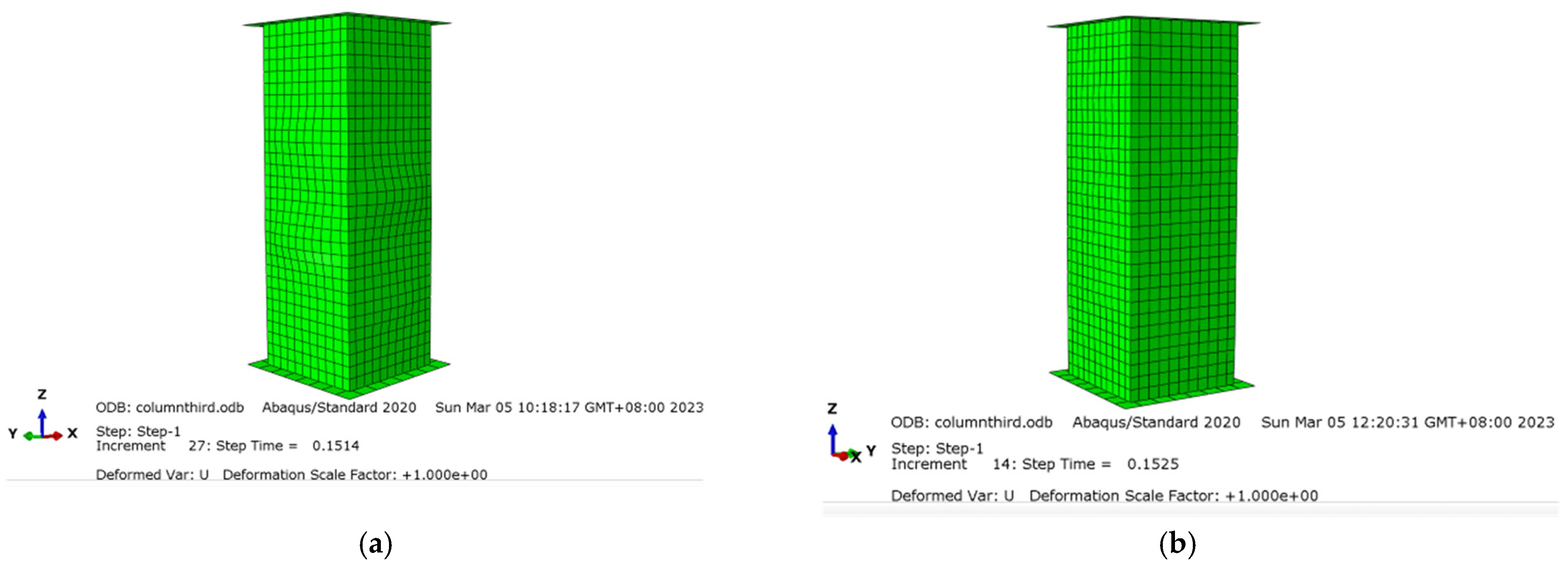
To provide direct visual evidence supporting the SI-based criterion, the deformation contours are extracted from eigenvalue buckling analysis for two representative specimens: one with B/t exceeding the proposed upper limit (where SI < 1.0, indicating premature local buckling prior to the peak load) and one within the recommended range (where SI > 1.0, indicating no local buckling prior to the peak load).
As shown in
Figure 5, the deformation contours of the two specimens are distinctly different:
- (1)
For the specimen with B/t = 75, which exceeds the proposed upper limit, a pronounced local buckling mode is clearly observed, with multiple half-waves developing in the central region of each steel tube face. This indicates that the steel tube is susceptible to premature local buckling before reaching the peak load, consistent with the SI value (SI < 1.0) confirming that local buckling occurred prior to the ultimate state.
- (2)
For the specimen with B/t = 37.5, which falls within the proposed recommended range, no significant local buckling mode is observed—the mode shape remains essentially flat with negligible out-of-plane deformation. This confirms that the steel tube does not buckle prior to the peak load, consistent with the SI value (SI > 1.0), indicating stable composite action.
These deformation contours provide direct visual confirmation that the
SI-based criterion correctly identifies whether premature local buckling occurs before the specimen reaches its peak load. The clear distinction between the two cases demonstrates the effectiveness of the proposed
B/
t limits in preventing premature local buckling. It should be noted that the eigenmode shapes shown in
Figure 5 are obtained from linear eigenvalue buckling analysis and represent only the idealized elastic buckling modes. They are used here for illustrative purposes to show the deformed shape patterns, but they do not by themselves establish the timing of local buckling relative to the peak load. The actual occurrence of local buckling was determined through the geometrically and materially nonlinear FE analysis (GMNIA), in which the evolution of out-of-plane displacement was monitored throughout the loading history. For the specimen with
SI < 1.0 (
B/
t = 75), the out-of-plane displacement grew rapidly before the peak load, confirming that local buckling initiated prior to reaching the ultimate state. For the specimen with
SI > 1.0 (
B/
t = 37.5), no significant out-of-plane growth was observed until the post-peak stage, confirming that local buckling, if any, occurred after the peak load. Thus,
Figure 5 is provided as a visual supplement, while the
SI-based classification is supported by the full nonlinear analysis described above.
In summary, the following conclusions can be drawn:
- (1)
In terms of conservatism, the order of formulas from high to low is: Equation (10) = Equation (9) > Equation (8) > Equation (7) > Equation (6). A systematic comparison of the five existing design formulas for each steel–concrete combination is summarized in
Table 5;
- (2)
For low-strength concrete, the minimum wall thickness required to avoid premature local buckling of steel tubes prior to the ultimate bearing capacity rises with the increase in steel strength grade;
- (3)
The minimum wall thickness for preventing premature steel tube buckling before the ultimate state decreases as the concrete strength grade increases;
- (4)
Concrete strength affects the degree of adverse influence induced by steel tube local buckling occurring before the ultimate load;
- (5)
B/t should not be excessively large, so as to avoid premature local buckling of steel tubes and enable full utilization of the strength potential of both steel and concrete materials;
- (6)
The cold-forming effect has a negligible influence on the elastic buckling of steel tubes.
To provide a quantitative basis for the classification in
Table 5, the following definitions are adopted: Unsafe: The formula allows a
B/
t value that leads to
SI < 0.95 for a given material combination, indicating that premature local buckling occurs significantly before the peak load. Near critical: The formula’s limit yields 0.95 ≤
SI ≤ 1.05, indicating that the predicted critical
B/
t is close to the numerical threshold. Safe: The formula limits
B/
t to values that yield
SI > 1.05, indicating that local buckling is adequately prevented. Overly conservative: The formula’s limit yields
SI > 1.15, indicating that the limit is more restrictive than necessary by a margin exceeding 15%, which may lead to uneconomical designs.
4. The Optimal Matching of Steel and Concrete
Provided that elastic buckling of the steel tube is prevented, both the steel tube and core concrete can be fully utilized when the composite member reaches its sectional resistance [
12,
13,
14,
15,
16,
17,
18,
19,
20,
21,
22]. Therefore, the contribution of steel tube is defined as
θ, which can be calculated by Equation (11).
Among the five design formulas compared in
Section 3, Eurocode 4 [
2] exhibits the most balanced performance—it provides moderate conservatism and closely approximates the critical buckling state across multiple working conditions. Therefore, the upper bound (
β) of the proposed
B/
t limits is taken from EC4 to ensure reliable local buckling prevention.
When
θ < 45%, the steel tube is too slender or too thin, contributing insufficiently to the sectional resistance. The member behaves similarly to a plain concrete column with limited ductility, and the confining effect of the steel tube is not effectively mobilized. When
θ > 55%, the steel tube is over-designed relative to the concrete core. The concrete is insufficiently stressed to benefit from triaxial confinement, and the steel’s strength potential is not fully utilized in a cost-effective manner. Within 45% ≤
θ ≤ 55%, the steel tube and the core concrete contribute comparable shares to the total load-bearing capacity, while the confinement effect is optimally activated. This ensures both material efficiency and satisfactory ductility of the composite member. This rational range is consistent with the recommended steel contribution ratios for optimally designed CFST columns reported in the literature [
6,
7], confirming its general applicability. The corresponding
B/
t limits for each steel–concrete combination are then derived from the
θ–
B/
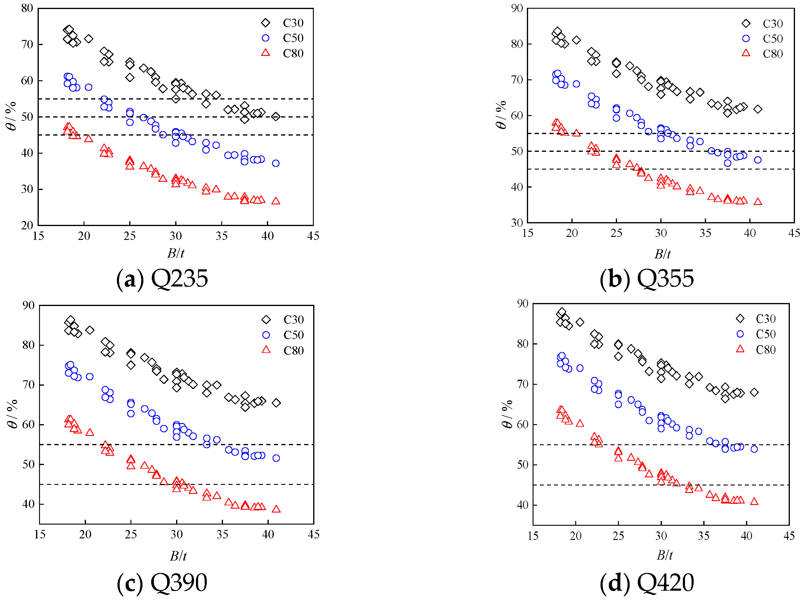
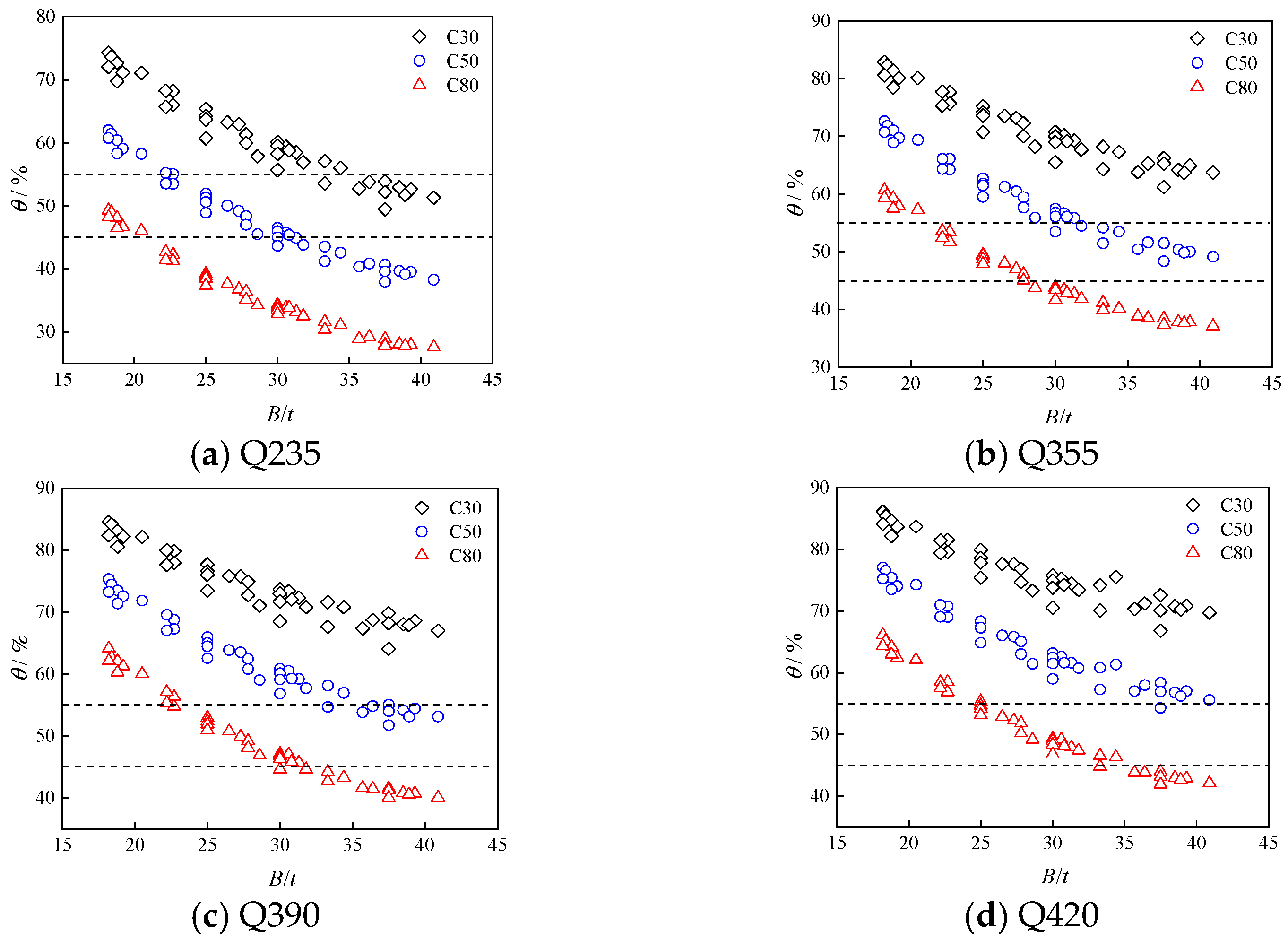
t relationships shown in
Figure 6 and
Figure 7, and are subsequently bounded by the local buckling limits of EC4 [
2] to ensure structural safety. It should be clarified that the welding residual stresses in CFTWST columns affect the effective yield strength and the inelastic load-bearing capacity of the steel tube, but they do not alter the elastic buckling stress. The elastic buckling stress of a plate depends only on the elastic modulus, Poisson’s ratio, and the plate geometry (
B/
t ratio, boundary conditions). These parameters are not significantly affected by the welding process. Therefore, the upper *
B/
t* limit derived from the elastic local buckling criterion (EC4 [
2]) is identical for both CFTWST and CFCFST columns. However, the tensile residual stresses near the weld seams reduce the effective yield strength of the steel section, meaning that for the same cross-sectional dimensions, the steel tube in a CFTWST column contributes less to the total load-bearing capacity than its CFCFST counterpart, where cold-forming enhances the corner yield strength. Consequently, to achieve the same balanced steel contribution ratio (
θ = 45–55%), a CFTWST column requires a smaller
B/
t (i.e., a thicker wall) than a CFCFST column. So, the lower-bound efficiency limits differ between the two tube types, while the upper-bound safety limits remain the same.
In actual engineering, although the lateral confinement force of steel tube to concrete varies with the change in parameters, for a given concrete strength grade, the triaxial compressive ultimate strength cannot increase indefinitely. Therefore, the key to the optimal use of CFST column, namely the optimal matching of steel and concrete, is that the increase in the member strength comes simultaneously from the steel, concrete and the confinement provided by the steel tube on concrete, that is θ between 45% and 55%. The optimal use of CFTWST and CFCFST columns may differ with the changes in steel tube property, concrete area and constraint effect; hence, the optimal matching of steel and concrete of CFTWST and CFCFST stub square columns is discussed through θ in this section, respectively.
For square CFST columns, the present studies only give the upper limit of
B/
t from the perspective of preventing elastic buckling of steel tubes. In this paper, ranges of
B/
t are given from the perspective of the optimal matching of materials for engineering design reference. The differentiated
B/
t limits proposed in this study are developed based on the unilateral confined thin-plate buckling theory specified in Eurocode 4 [
2]. It should be noted that the upper limits to avoid elastic local buckling are identical for both square CFTWST and CFCFST columns. Parametric analyses in
Section 3 verify that cold-forming strain hardening exerts negligible influence on elastic buckling performance of steel plates, which is governed only by steel elastic modulus and plate geometry. In contrast, the lower bound limits corresponding to the optimal steel contribution ratio differ significantly between the two tube types due to manufacturing-induced mechanical discrepancies. Cold forming elevates the equivalent yield strength of steel profiles, especially at tube corners, which enables CFCFST columns to reach the optimal steel contribution ratio (
θ = 45% and 55%) under larger
B/
t values. For tailor-welded tubes, welding tensile residual stress near weld seams reduces the effective critical buckling stress of tube walls. Therefore, a stricter lower
B/
t threshold is required for CFTWST members to maintain balanced steel-concrete matching and efficient material utilization. All final recommended
B/
t ranges are further constrained by the elastic buckling threshold from Eurocode 4 [
2] to guarantee structural safety against premature local buckling.
4.1. CFTWST Columns
As evident in
Figure 6, there is a gradual reduction in
θ as concrete strength rises. Meanwhile, a decrease in
B/
t corresponds to a gradual elevation in
θ.
Figure 6.
Steel contribution ratio θ versus B/t for CFTWST columns under different concrete grades.
Figure 6.
Steel contribution ratio θ versus B/t for CFTWST columns under different concrete grades.
For Q235-C30 CFTWST, when B/t is less than 30, θ has exceeded 55%. It can be considered that the increment of member strength mainly comes from the steel tube, while the concrete and confinement have little influence on strength elevation, which indicates that the concrete has reached its ultimate strength of triaxial compression. The further reduction in B/t mainly improves the effect of steel tube, but not for steel tube, concrete and confinement simultaneously. When B/t is more than 35, θ remains essentially. This phenomenon comes from the fact that, when B/t is less than 35, the steel tube can provide good confinement on the concrete though the steel content decreases, therefore the strength provided by the concrete remains. The reduction in the member strength is mainly caused by the steel tube, hence θ decreases as B/t increases. When B/t is more than 35, which will further reduce the steel content, the steel tube cannot provide good confinement to the concrete, and the strength provided by the concrete will also be greatly reduced. The decrease in member strength results from both the steel tube and concrete, leading to a relatively stable θ. Therefore, for Q235-C30 CFTWST columns, a B/t range between 30 and 35 is recommended. In the case of Q235-C50 CFTWST columns, when B/t exceeds 30, θ is less than 45%. Conversely, when B/t is less than 22.5, θ surpasses 55%. Further reduction in B/t primarily enhances the steel tube’s effectiveness. Therefore, the optimal B/t range is between 22.5 and 30 for Q235-C50 CFTWST columns. Regarding Q235-C80 CFTWST columns, when B/t drops below 20, θ slightly exceeds 45%. When B/t falls below 17.5, θ remains below 50%, suggesting a potential issue with excessively large t. Such small B/t values may pose challenges in construction for CFTWST columns. Consequently, the use of Q235-C80 CFTWST columns does not satisfy the selected steel contribution criterion.
For Q355-C30 CFTWST columns, when B/t is greater than 37.5, θ remains essentially small; thus, it can be considered that the confinement of steel tube on concrete is very small. When B/t increases to 42.5, θ is still 60%; hence, Q355-C30 CFTWST columns do not satisfy the selected steel contribution criterion. For Q355-C50 CFTWST columns, when B/t is less than 30, θ has exceeded 55%. When B/t is slightly less than 42.5, θ is slightly more than 45%; hence, B/t should be taken between 30 and 42.5 for Q355-C50 CFTWST columns. For Q355-C80 CFTWST columns, when B/t is less than 20, θ has exceeded 55%. When B/t is greater than 27.5, θ has been less than 45%; therefore, B/t should be taken between 20 and 27.5 for Q355-C80 CFTWST columns.
For Q390-C30 CFTWST columns, when B/t is more than 37.5, θ is remain essentially, it can be considered that the confinement of steel tube on concrete is very small. When B/t increases to about 42.5, θ is still 65%, hence Q390-C30 CFTWST columns do not satisfy the selected steel contribution criterion; For Q390-C50 CFTWST columns, when B/t is less than 35, θ has exceeded 55%. When B/t is greater than 35, the decreasing speed of θ slows down gradually. When B/t reaches 42.5, θ is still about 50%, and when B/t ranges from 35 to 42.5, the reduction of θ is 5%. Therefore, it is speculated that B/t should be taken between 35 and 52 for Q390-C50 CFTWST columns. For Q390-C80 CFTWST columns, when B/t is less than 22.5, θ has exceeded 55%. When B/t is greater than 30, θ has been less than 45%, hence B/t should be taken between 22.5 and 30 for Q390-C80 CFTWST columns.
For Q420-C50 CFTWST columns, when B/t is less than 35, θ has exceeded 55%. When B/t is greater than 35, θ remain essentially, it can be considered that the confinement of steel tube on concrete is very small, hence Q420 steel shall not be matched with low-strength concrete; For Q420-C80 CFTWST columns, when B/t is less than 22.5, θ has exceeded 55%. When B/t is greater than 32.5, θ has been less than 45%, therefore B/t should be taken between 22.5 and 32.5 for Q420-C80 CFTWST columns.
The
B/
t limits derived from the optimal matching criterion are then integrated with the local buckling provisions of EC4 [
2], as shown in
Table 6.
β is the upper limit of
B/
t to prevent local buckling of steel tube before reaching the ultimate strength of member, which is defined according to EC4 [
2].
It is important to clarify that the upper and lower
B/
t limits proposed in this study serve fundamentally different purposes. The upper bound is a safety requirement derived from the elastic local buckling criterion specified in Eurocode 4 [
2]. It defines the maximum
B/
t ratio beyond which the steel tube would buckle elastically before reaching its yield stress, thereby impairing the composite action. This upper bound is identical for both CFTWST and CFCFST columns, as the elastic buckling stress depends only on the plate geometry and elastic modulus, which are not significantly affected by the forming process. Exceeding this limit is not permitted in design. The lower bound, in contrast, is a material efficiency recommendation derived from the steel contribution ratio
θ = 45–55%. It is not a safety requirement but a design recommendation to avoid over-designed sections where the steel tube is unnecessarily thick relative to the concrete core. When the lower bound is not satisfied (i.e.,
B/
t is smaller than the recommended range), the member is still safe in terms of local buckling—it merely implies that the steel tube is over-sized, leading to an uneconomical section. This lower bound differs between CFTWST and CFCFST columns because the welding residual stresses in CFTWST sections reduce the effective contribution of the steel, requiring a more conservative (stricter) limit to achieve the same level of material balance. Thus, the proposed system provides a dual-control framework: engineers must ensure that
B/
t does not exceed the upper bound (safety), and they are recommended to choose
B/
t above the lower bound (efficiency) for economical design.
As can be seen from the analysis above that when the strength of steel tube is certain, the upper and lower limits of
B/
t decrease with the increase in concrete strength. Therefore, the lower limit of
B/
t can be determined according to the concrete with slightly lower strength, and the upper limit of
B/
t can be determined according to the concrete with slightly higher strength for the concrete strength not listed in
Table 6.
For certain material combinations where the recommended lower bound exceeds the upper bound (β), under the proposed dual-criteria framework, no feasible B/t falls within the selected steel contribution ratio range. In such cases, the design is governed by the upper safety limit, and the material combination should be reconsidered to achieve both safety and efficiency. From a practical standpoint, this situation typically arises when high-strength steel is paired with low-strength concrete, where the steel tube would need to be excessively thick to achieve the balanced contribution ratio, yet the elastic buckling limit imposes a stricter upper bound.
4.2. CFCFST Columns
As can be seen from
Figure 7,
θ gradually reduces with the rise in concrete strength. Meanwhile
θ gradually increases as
B/
t decreases.
Figure 7.
Steel contribution ratio θ versus B/t for CFCFST columns under different concrete grades.
Figure 7.
Steel contribution ratio θ versus B/t for CFCFST columns under different concrete grades.
For Q235-C30 CFCFST columns, when
B/
t is less than 32.5,
θ has exceeded 55%. It can be considered that the concrete has reached the ultimate strength of triaxial compression. The further reduction of
B/
t mainly improves the effect of steel tube, but not for steel tube, concrete and confinement simultaneously. When
B/
t is greater than 35, the decreasing speed of
θ slows down gradually. When
B/
t reaches to 42.5,
θ is still about 50%, and when
B/
t ranges from 35 to 42.5, the reduction of
θ is about 5%. Therefore, it is speculated that
B/
t should be taken between 32.5 and 52 for Q235-C30 CFCFST columns. For Q235-C50 CFCFST columns, when
B/
t is less than 22.5,
θ has exceeded 55%. The further reduction of
B/
t mainly improves the effect of steel tube. When
B/
t is more than 30,
θ is less than 45%, hence
B/
t should be between 22.5 and 30 for Q235-C50 CFCFST columns. For Q235-80 CFCFST columns, when
B/
t is less than 20,
θ slightly more than 45%, when
B/
t is less than 17.5,
θ is about 50%.
B/
t is too small, which may mean that
t is too large. According to JG /T178-2005 [
23], the maximum
t of cold-formed square steel tube is 22 mm. Therefore, Q235-C80 CFCFST columns should not be used.
For Q355-C30 CFCFST columns, when B/t is more than 37.5, the decreasing speed of θ slows down gradually. When B/t increases to 42.5, θ is still 65%. With the increase of B/t, the confinement of steel tube on concrete is very small, θ remains essentially, hence Q355-C30 CFCFST columns do not satisfy the selected steel contribution criterion. For Q355-C50 CFCFST columns, when B/t is less than 30, θ has exceeded 55%. When B/t is slightly less than 42.5, θ is slightly greater than 45%, therefor B/t should be taken between 30 and 42.5 for Q355-C50 CFCFST columns. For Q355-C80 CFCFST columns, when B/t is less than 20, θ has exceeded 55%. When B/t is more than 27.5, θ has been less than 45%, hence B/t should be taken between 20 and 27.5 for Q355-C80 CFCFST columns.
For Q390-C30 CFCFST columns, when B/t is more than 35, the decreasing speed of θ slows down gradually. When B/t increases to about 42.5, θ is still 67.5%. With the increase of B/t, the confinement of steel tube on concrete is very small, hence Q390-C30 CFCFST columns shall not be used. For Q390-C50 CFCFST columns, when B/t is less than 35, θ has exceeded 55%; When B/t is more than 35, with the increase of B/t, the decreasing speed of θ slows down gradually. When B/t is 42.5, θ is still about 52.5%, and when B/t ranges from 35 to 42.5, the reduction of θ is 2.5%. Therefore, it is speculated that B/t should be taken between 35 and 67 for Q390-C50 CFCFST columns. For Q390-C80 CFCFST columns, when B/t is less than 22.5, θ has exceeded 55%. When B/t is more than 31, θ has been less than 45%, therefore B/t should be taken between 22.5 and 31 for Q390-C80 CFCFST columns.
For Q420-C30 CFCFST columns, when B/t is 41, θ is still 70%. With the increase of B/t, the confinement of steel tube on concrete is very small, θ remains essentially, hence Q420-C30 CFCFST columns shall not be used; For Q420-C50 CFCFST columns, when B/t is less than 41, θ has exceeded 55%. When B/t is more than 41, the decreasing speed of θ slows down gradually. With the increase of B/t, the confinement of steel tube on concrete is very small, θ remains, therefore, the lower limit of B/t should be 41 for Q420-C50 CFCFST columns. For Q420-C80 CFCFST columns, when B/t is less than 25, θ has exceeded 55%. When B/t is more than 35, θ has been less than 45%, hence B/t should be taken between 25 and 35 for Q420-C80 CFCFST columns.
The
B/
t limit obtained from the perspective of the optimal matching of steel and concrete is combined with the provisions of EC4 [
2], as shown in
Table 7.
β is the upper limit of
B/
t to prevent local buckling of steel tube before reaching the ultimate strength of member, which is defined according to EC4 [
2].
For concrete grades not listed in
Table 7, the lower and upper bounds of
B/
t can be determined by interpolation or by referring to the nearest available grade, and the upper limit of
B/
t can be determined according to the concrete with slightly higher strength.
4.3. Experimental Validation of the Proposed B/t Limits
To provide experimental support for the proposed
B/
t limits, a retrospective check was conducted against the experimental database compiled in the authors’ previous study [
11], which includes 14 in-house tests and 210 specimens collected from the literature. From this database, specimens with explicitly reported local buckling observations were examined.
The results show that among the specimens whose
B/
t values fall within the proposed ranges (
Table 6 and
Table 7 of the present paper), no premature local buckling was observed prior to the peak load—all these specimens exhibited stable behavior with
SI > 1. In contrast, specimens with
B/
t exceeding the proposed upper bounds consistently showed local buckling before the ultimate state.
This retrospective check, based on a large experimental database, provides direct support for the proposed upper-bound limits. The detailed experimental data and source references are already available in the database of [
11] and not duplicated in this manuscript.
4.4. Comparison with Existing Codes
The proposed differentiated
B/
t limits possess clear practical advantages compared with existing international design provisions. Current design standards, including GB 50936 [
3], Eurocode 4 [
2], AISC 360 [
1], and published theoretical formulas [
4,
5], only supply a single upper bound to avoid local buckling, without considering material matching efficiency.
As quantitatively summarized in
Section 3, obvious discrepancies exist in their safety margins and conservatism levels: Equation (6) delivers insufficient safety reserves under high-strength steel paired with low-strength concrete; Equations (8)–(10) adopt overly strict thresholds, which significantly increase steel consumption and reduce section economy; Equation (7) maintains a moderate safety margin and balanced material utilization, hence it is selected as the upper-bound benchmark in this research. Different from the single-sided limit in existing codes, this study establishes a dual-control framework consisting of upper and lower
B/
t boundaries:
The upper limit derived from the Eurocode 4 elastic buckling criterion guarantees sufficient safety redundancy to eliminate premature local buckling before the column reaches its ultimate resistance.
The lower limit determined by the optimal steel contribution ratio range (θ = 45–55%) avoids redundant thick steel tubes and maximizes the collaborative bearing performance of steel and concrete, thus improving material economy.
This two-sided limit system enables targeted sectional optimization for different fabrication types. Owing to cold-forming strain hardening that elevates the steel equivalent yield strength, CFCFST columns can maintain acceptable safety and balanced steel–concrete matching at larger
B/
t values than welded counterparts under identical material grades (as can be observed from the comparative values in
Table 6 and
Table 7). In contrast, tensile welding residual stresses degrade the local stability of CFTWST tubes, demanding tighter
B/
t thresholds to retain reliable safety margins.
Compared with the unified single limits in existing codes that either waste steel for cold-formed members or introduce hidden stability risks for welded members, the differentiated dual-range recommendations provide designers with clear, classified criteria to simultaneously satisfy structural safety and material economy according to actual tube production techniques.
4.5. Practical Significance of Differentiated B/t Limits
The proposed differentiated B/t limits for CFCFST and CFTWST columns offer practical value in engineering design by enabling manufacturing-process-specific cross-section optimization.
As established in
Section 3, the upper limits for preventing elastic local buckling are identical for both tube types, since cold forming does not influence elastic buckling behavior. The differentiation arises from the lower limits, which are governed by the optimal steel contribution ratio (
θ = 45–55%).
For CFCFST columns, the cold-forming effect enhances the equivalent yield strength of the steel section, particularly at the corners. This allows the column to maintain the optimal steel–concrete balance at a larger B/t ratio, translating into reduced steel consumption without compromising safety. For CFTWST columns, welding residual stresses reduce the effective load-carrying efficiency of the steel tube, necessitating a strict B/t limit to ensure adequate structural performance.
In current design practice, applying a unified B/t limit to both tube types would either over-design cold-formed sections (leading to material waste) or under-design welded sections (posing safety risks). The proposed differentiated recommendations provide a rational basis for manufacturing-process-conscious design, enabling engineers to achieve both safety and economy in square CFST column design.
4.6. Limitations and Future Work
The proposed
B/
t limits are derived primarily from FE parametric analyses. Although the FE model has been rigorously validated against 14 in-house experiments and 210 literature specimens [
11], several inherent limitations of relying solely on numerical simulations should be acknowledged. First, the FE model inevitably involves simplifications of material-constitutive relationships, welding residual stress patterns, and geometric imperfection assumptions. The actual structural response may deviate from numerical predictions due to factors such as construction tolerances, material variability, and unpredictable loading histories. Second, while the retrospective check against the experimental database provides indirect support for the proposed limits, direct experimental verification on newly designed specimens specifically targeting the proposed
B/
t ranges has not yet been conducted. This is a common limitation of numerical parametric studies and is a priority for our ongoing research.
In addition to the above methodological considerations, the proposed B/t limits are derived from parametric analyses covering the practical ranges of steel yield strengths (Q235–Q420) and concrete compressive strengths (C30–C80). The finite element model incorporates welding residual stress distributions and geometric imperfections following established engineering provisions. While the parametric coverage inherently accounts for the influence of material strength variations, a systematic quantitative sensitivity analysis specifically targeting residual stress magnitudes and imperfection amplitudes has not been performed in this study. Such an analysis will be carried out in our future research to further quantify the relative influence of these factors and to enhance the robustness assessment of the proposed limits.
The proposed B/t limits are derived from stub column tests and FE analyses under axial compression. Their applicability to slender columns and columns under eccentric loading requires further investigation. For practical design, the proposed limits may be used as section-level checks to prevent premature local buckling, while global stability and second-order effects should be evaluated according to relevant design codes. For slender columns with large slenderness ratios, global flexural buckling rather than local plate buckling may become the dominant failure mode. However, this does not render the proposed section-level B/t limits invalid—local buckling and global buckling are independent failure modes, and both must be prevented in design. Therefore, for slender columns, the proposed limits should be used as a section-level check alongside global stability verification. Regarding non-axial loading such as eccentric compression and beam-column loading, asymmetric compressive stress distribution arises on the tube wall, which may alter the elastic and inelastic local buckling critical state. Direct application of the current B/t limits to such conditions requires further verification, as the strain gradient effects are not explicitly accounted for in the present study. Systematic parametric simulations covering various slenderness ratios and combined compression-bending loads will be conducted in follow-up research to supplement the applicable scope of the proposed B/t limits for general CFST members.