Article

An Innovative Hybrid Moment-Resisting Frame System Using Pultruded GFRP Profiles and Replaceable Steel Link Equipped with Ductile Pipe Sections

by
Radhika Sridhar
1,
Denise-Penelope N. Kontoni
2,3,* and
Ali Ghamari
4
1
School of Engineering and Technology, Walailak University, Nakhon Si Thammarat 80161, Thailand
2
Department of Civil Engineering, School of Engineering, University of the Peloponnese, GR-26334 Patras, Greece
3
School of Science and Technology, Hellenic Open University, GR-26335 Patras, Greece
4
Department of Civil Engineering, Il.C., Islamic Azad University, Ilam, Iran
*
Author to whom correspondence should be addressed.
Buildings 2026, 16(15), 2980; https://doi.org/10.3390/buildings16152980

Submission received: 29 June 2026 / Revised: 15 July 2026 / Accepted: 24 July 2026 / Published: 27 July 2026
(This article belongs to the Section Building Structures)

Abstract

Glass fiber-reinforced polymer (GFRP) is increasingly used in civil engineering because of its high strength-to-weight ratio, corrosion resistance, durability, and low maintenance requirements. However, its inherently brittle behavior and limited ductility restrict its application in seismic regions due to poor energy dissipation capacity. To address this limitation, this study proposes a novel hybrid system comprising pultruded GFRP profiles and a replaceable steel link with ductile pipe sections. The pipe element confines inelastic deformation to the steel components while keeping the GFRP members elastic. Numerical results demonstrate stable hysteretic behavior with no significant degradation in strength or stiffness, confirming the effectiveness of the proposed system. Also, increasing the ratio of the pipe thickness to the flange thickness of the steel link (β) ensures suitable performance provided that plastic hinge formation remains confined to the ductile pipe element and replaceable steel link. Adding the pipe element to the I-shaped steel link increases web stress when β ≤ 1.0 (leading to web yielding), while stresses in the flange, GFRP beam, and GFRP columns are reduced by 46–51%, 17–60%, and 15–40%, respectively. However, for β > 1.0, stresses in GFRP components are not reduced but slightly increase by 1–9% (negligible), making β > 1.0 not recommended. Also, by changing the β = 0.50 to 0.75 , 1.00 , 1.25 , and 1.50 , the flexural capacity, stiffness, and energy dissipation are enhanced by 1.51 times to 2.46 times, 1.18 times to 1.38 times, and 1.35 times to 1.68 times, respectively. Finally, the necessary design equations for the proposed system are presented.

1. Introduction

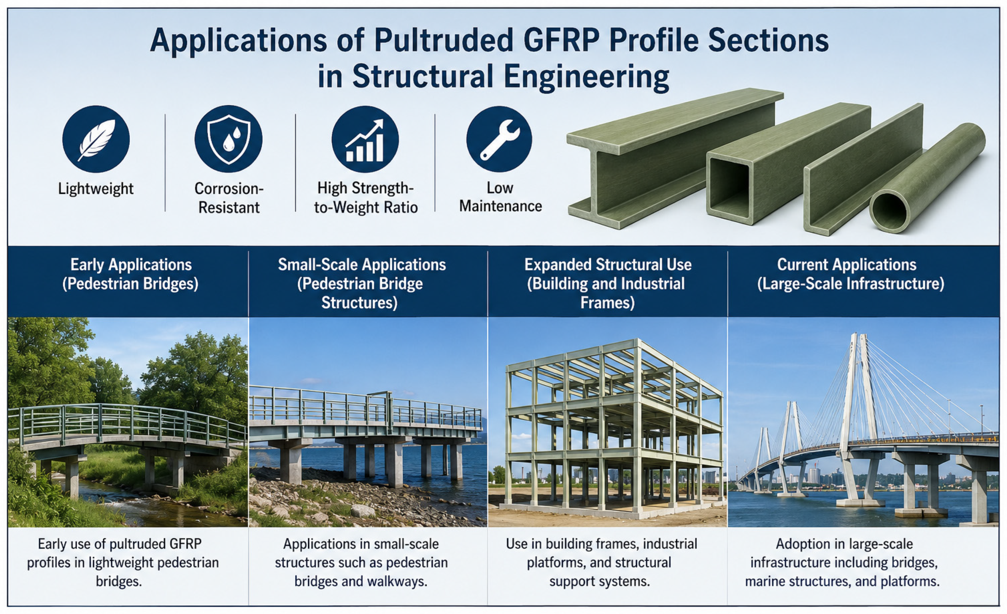
The persistent demand for durable, lightweight, and corrosion-resistant infrastructure has driven significant innovation in construction materials, with fibre-reinforced polymer (FRP) composites emerging as a viable alternative to conventional steel and concrete. Among these, glass fibre-reinforced polymer (GFRP) has garnered particular attention in structural engineering due to its advantageous properties, including a high strength-to-weight ratio, approximately one-quarter the weight of steel, superior corrosion resistance, and non-conductive characteristics [1]. These attributes render GFRP particularly suitable for applications in aggressive environments, such as marine structures, bridge decks, and chemical processing facilities, where traditional reinforcing materials are prone to deterioration. Figure 1 illustrates a schematic view of utilizing FRP in structural engineering.
The pultrusion manufacturing process has enabled the production of standardized GFRP profile sections, including I-beams, box sections, channels, and tubes, that can be directly employed as primary load-bearing members in civil infrastructure [2]. Unlike FRP reinforcing bars used in concrete, which have been the subject of design codes such as ACI 440.11-22 and CSA S806-12, pultruded GFRP profiles used as standalone structural sections present distinct challenges related to their anisotropic nature, low elastic modulus, and susceptibility to local buckling and web crippling failures [3,4]. These characteristics necessitate a dedicated investigation into their structural behaviour under various loading conditions.
The growing appeal of GFRP profiles in structural engineering stems from a unique combination of material and structural benefits that address many limitations of conventional construction materials. GFRP profiles typically exhibit a tensile strength comparable to or exceeding that of mild steel (300–600 MPa) while possessing only approximately 20–25% of the density of steel (1.5–2.0 g/cm3 versus 7.85 g/cm3 for steel) [1,3]. This high strength-to-weight ratio reduces transportation, handling, and erection costs, and allows for longer spans and lighter foundations. In seismic regions, reduced self-weight directly translates to lower inertial forces, enhancing overall structural resilience [4]. By using a lightweight structure with suitable ductility, the steel structure pertains to high energy dissipation capacity [5,6,7]. Unlike steel, which requires protective coatings or galvanisation in aggressive environments, GFRP profiles are inherently resistant to chlorides, acids, alkalis, and saltwater. This makes them ideal for marine piers, chemical plant platforms, wastewater treatment facilities, and bridge decks exposed to de-icing salts [2,8]. The elimination of regular painting and maintenance interventions yields significant life-cycle cost savings, often rendering GFRP more economical than steel over a 50–100-year service life [9]. GFRP is electrically and thermally non-conductive, unlike steel or aluminum. This property is critical for applications near railway electrification systems, power substations, telecommunication towers (where signal interference must be minimized), and magnetic resonance imaging (MRI) facility structures [3,10,11]. Furthermore, GFRP does not generate eddy currents, making it suitable for sensitive electronic environments. GFRP composites demonstrate excellent fatigue resistance under cyclic loading, with fatigue limits often exceeding 60% of static strength, compared to 40–50% for structural steel [4]. The glass fibres effectively arrest crack propagation, and the polymeric matrix absorbs energy under impact loads. Studies have shown that GFRP profiles retain over 85% of their initial stiffness after two million fatigue cycles [11]. Pultrusion allows the continuous production of profiles with custom fibre architectures (unidirectional rovings for axial stiffness, continuous filament mats for shear resistance, and woven fabrics for multi-directional strength) [2]. This enables engineers to optimize the profile’s mechanical response for specific loading scenarios—e.g., aligning fibres along principal stress trajectories in beams or columns. Modern GFRP formulations incorporate ultraviolet (UV) stabilisers and moisture-resistant resins (e.g., vinyl ester or isophthalic polyester), resulting in excellent long-term durability. Accelerated aging studies indicate that properly designed GFRP profiles retain over 80% of their initial flexural and compressive strength after 50 years of simulated outdoor exposure provided that service temperatures remain below the resin glass transition temperature (typically 80–110 °C) [1,12]. The lightweight nature of GFRP profiles facilitates manual handling without heavy lifting equipment, and prefabricated modular sections can be rapidly bolted or bonded on-site. Case studies report up to 60% reduction in installation time compared to equivalent steel structures [5,13]. Although GFRP production is energy-intensive, the extended service life, reduced maintenance, and potential for end-of-life recycling (via pyrolysis or cement kiln co-processing) contribute to a favourable life-cycle environmental profile. Additionally, the absence of corrosion eliminates the need for toxic anti-corrosive paints [3,14].
Despite the inherent advantages of GFRP profiles, their effective implementation in structural systems is critically dependent on the performance of connections—particularly those incorporating steel fasteners. Steel-bolted connections remain the most prevalent method for joining GFRP profiles to each other and to conventional steel members owing to their ease of assembly and disassembly for inspection and their compatibility with existing construction practices [15]. A critical review of 350 published experimental tests on bolted connections in pultruded FRP revealed that connection strength often governs the overall design of FRP frames, with resistance factors (ϕ-factors) prescribed in ASCE/SEI 74-23 generally lower than those for conventional materials due to higher uncertainty and brittleness [16]. That statistical analysis employing first-order reliability methods highlights the need for refined resistance models that account for geometric parameters, fibre architecture, and hole preparation quality. The use of steel cleats (angles) and gusset plates represents a practical solution for beam-to-column joints in GFRP frames. Recent experimental investigations on exterior weak-axis beam-to-column bolted connections between GFRP I-shaped pultruded profiles using stainless steel cleats demonstrated that cleat thickness significantly influences flange-cleated configurations but not web-cleated connections [14]. Under monotonic and cyclic loads, flange-cleated connections exhibited semi-rigid behaviour, while web-cleated connections behaved as pinned joints. Both configurations showed substantial resistance and rotation capacity—markedly superior to connections using GFRP cleats reported in prior studies. However, cyclic tests revealed limited energy dissipation capacity, indicating that such connections are not suitable for seismic energy dissipation without supplemental devices [14]. Notably, premature shear-out failure occurred when beam edge distances were insufficient, underscoring the importance of detailing geometric parameters. To address the stress concentrations inherent in bolted-only connections, hybrid adhesive-bolted joints have emerged as a superior alternative. The failure mode shifted from brittle bolt-bearing failure to more gradual adhesive debonding followed by bolt engagement. Finite element (FE) analyses using ANSYS confirmed that hybrid connections achieve higher load utilisation of the GFRP profile’s longitudinal strength, which can reach up to 1400 MPa in tension, compared to bolted-only configurations where transverse and shear strengths (typically tens of MPa) often govern design [15]. For joining tubular GFRP profiles to steel members, bonded sleeve connections offer distinct advantages. Zhang et al. [16] numerically investigated bonded sleeve connections combining adhesive bonding with endplates and bolts, comparing them against conventional steel angle connections. Parametric studies revealed that endplate thickness dominates initial stiffness and elastic moment capacity, while the inclusion of central one-sided bolts improves elastic moment capacity by providing redundancy and load-path continuity. Conversely, GFRP profiles and plates are increasingly employed to strengthen existing steel connections. Khelifa et al. [17] developed numerical models for steel connections strengthened with GFRP and CFRP under monotonic and cyclic loading by utilising the Cohesive Zone Model (CZM) in Abaqus to simulate adhesive behaviour. Their parametric study on I-section steel connections demonstrated that GFRP strengthening effectively enhances load-carrying capacity without adding significant dead weight or corrosion risk—advantages over traditional steel plate strengthening. However, the effectiveness of GFRP strengthening was found to be highly dependent on adhesive selection, surface preparation, and the stiffness mismatch between steel (200 GPa) and GFRP (20–40 GPa).
Despite the aforementioned advantages, the widespread adoption of GFRP profiles has been constrained by several challenges: low elastic modulus (typically 20–40 GPa, compared to 200 GPa for steel), anisotropic failure modes (fibre rupture, matrix cracking, delamination, and interface debonding), and susceptibility to local buckling and web crippling due to thin-walled sections [2,4,12]. Early studies on pultruded GFRP beams identified that flexural capacity is often governed by compression flange local buckling rather than material strength. Dehshirizadeh et al. [2] conducted a state-of-the-art review on pultruded GFRP box beams and demonstrated that current design expressions (ASCE 2010) overestimate critical buckling stresses by up to 40%, leading to unconservative predictions. Similarly, Al-Ezzi et al. [8] reviewed concrete-filled GFRP tube composite beams, showing that concrete infill effectively delays local buckling and enhances ductility, though failure is often triggered by shear debonding at the tube–concrete interface. Web crippling—a localised crushing failure at support or load points—is particularly critical for thin-walled GFRP I-sections and channels. Soumbourou et al. [4] systematically reviewed experimental, numerical, and theoretical analyses of web crippling in pultruded GFRP profiles. Their synthesis identified that elevated temperatures (above 60 °C) reduce crippling capacity by 30–50% due to resin softening and that current design standards (AASHTO, Eurocode-inspired FRP provisions) lack validated reduction factors for temperature effects. They further highlighted the promising role of machine learning models to predict crippling strength based on geometry, loading configuration, and material properties. Khalil et al. [9] experimentally and theoretically investigated GFRP I-profile composite columns under axial compression. Their results showed that filling the profile with concrete or confining with FRP wraps increased load capacity by 150–200% and transformed the failure mode from unstable local buckling to ductile concrete crushing. For truss systems, the full-scale testing of pultruded GFRP trusses with through-bolt mechanical inserts revealed that connections often govern capacity; Hizam et al. [18] demonstrated that stainless steel through-bolts with adhesively bonded mechanical inserts enabled a double-chorded GFRP truss to resist up to 450 kN under four-point bending, with minor bearing damage observed at diagonal member joints when axial compression forces exceeded theoretical capacities by only 2%. The performance of GFRP profiles is critically dependent on connection design. Bolted joints suffer from stress concentrations and bearing failure, while bonded joints offer uniform stress transfer but require surface preparation and are sensitive to moisture. Hybrid joints exhibit superior strength and fatigue life [3,9,14]. Steel-bolted connections, despite their widespread use, require careful detailing of edge distances, bolt spacing, and washer sizes to prevent premature brittle failures [10,14]. Despite extensive research on the use and numerous advantages of GFRP in civil engineering applications, the widespread adoption of pultruded GFRP profile sections remains challenging due to their inherently brittle behavior. This limitation has created a significant knowledge gap regarding the development of structural systems that can effectively exploit the benefits of GFRP while mitigating its brittle failure characteristics. Therefore, this study aims to address this challenge by proposing and evaluating an innovative approach to improve the structural performance and applicability of pultruded GFRP profile sections.

2. The Proposed Approach to the Use of GFRP in Hybrid Systems

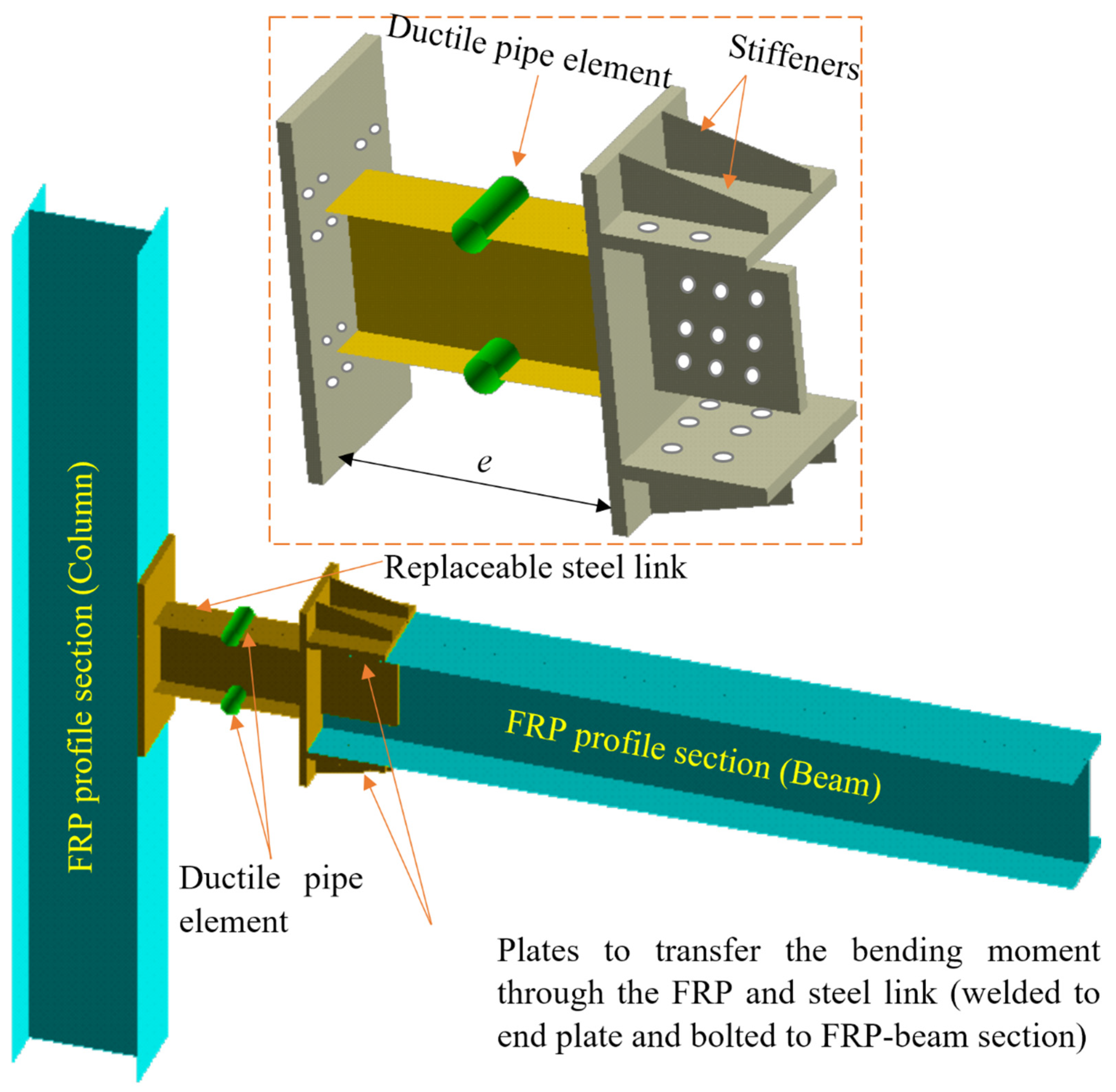
Pultruded fiber-reinforced polymer (FRP) profiles offer significant advantages such as a high strength-to-weight ratio, excellent corrosion resistance, low maintenance requirements, and ease of installation. However, they also present notable drawbacks, including low ductility and the requirement for complicated connections to be used as a moment-resisting frame (MRF) system for seismic zones. To capitalize on the inherent benefits of pultruded FRP profiles while effectively mitigating or eliminating their primary limitations, this paper introduces an innovative structural concept and design methodology. The proposed approach not only preserves the well-documented advantages of FRP composites but also addresses key shortcomings through novel material combinations, geometric optimizations, and/or hybrid systems, thereby expanding the practical applicability of pultruded FRP members for a moment-resisting system, as illustrated in Figure 2. As revealed in this figure, the hybrid system features the pultruded FRP profile section connected with a steel link. In civil engineering applications of pultruded profiles, the primary distinction between carbon fiber-reinforced polymer (CFRP) and glass fiber-reinforced polymer (GFRP) lies in the balance between structural performance and cost. CFRP offers significantly superior mechanical properties; it is characterized by a much higher tensile strength and elastic modulus, leading to enhanced load-carrying capacity and stiffness. Research on pultruded sections has demonstrated that CFRP provides substantially greater improvements in ultimate strength and stiffness, with studies showing significant enhancements [19,20]. However, this enhanced performance comes with a much higher material cost, making it less economical for large-scale, general-purpose applications [21]. Conversely, GFRP is the more cost-effective and widely used option for pultruded profiles in infrastructure, such as pedestrian bridges and building components [22]. While GFRP has a lower stiffness and strength, it is favored for its affordability and adequate performance for most standard structural needs [19,22]. Consequently, a hybrid approach is often employed in practice, where an economical GFRP profile serves as the primary structural member and is selectively strengthened or wrapped with high-performance CFRP in critical zones to achieve a cost-effective balance of stiffness, ductility, and strength [19,20,21,22,23]. Accordingly, the pultruded GFRP profiles are used for beams and columns in this study. As revealed in Figure 2, the steel link is intended to yield and act as a ductile fuse, and the FRP component remains elastic so that the link acts as a ductile fuse to dissipate imposed seismic energy. Two end plates are connected to the ends of the ductile steel that connect to columns and beams. At the location connected to the FRP beam, a shear plate (to carry the shear loading) and top and bottom plates (to transfer the flexural bending moment) are connected to the end plate. Also, stiffeners are installed on the top and bottom plates to prevent any buckling of the plates. As shown in this figure, the connection of the FRP profile section to the ductile link is performed without any complication. Also, since the ductile link is expected to yield, and the elastic performance of the FRP is due to its inherent properties, replacing the ductile link is done after a severe earthquake.
The lateral load applied to the MRF system causes forces to develop in the main beam and column. Since the GFRP components are expected to remain elastic, they are designed for an amplified capacity of the replaceable steel link. Accordingly, Equations (1) and (2) must be satisfied.
M p l i n k M M s , G F R P
V p l i n k V V s , G F R P
M p l i n k and V p l i n k are the plastic moment and shear plastic capacity of the steel link, respectively. Also, M s , G F R P and V s , G F R P , are, respectively, the flexural capacity and shear capacity of the GFRP beam. Similarly, M and V are coefficient factors less than one as reduction factors for bending moment capacity and shear capacity, respectively, which are measured as M = 0.9 and V = 0.8 .
Also, the flexural capacity of the top and bottom plate, M p l , must be greater than the M s , F R P . Accordingly, M p l M M s , F R P must be satisfied. As the flexural capacity of the connections creates couple forces, the equation of t p l b p l M s , G F R P 0.9 d b F y must be satisfied to remain elastic in connections. In this equation, t p l , b p l , d b and F y are the thickness of the top (as well as bottom) plates, the width of the top (as well as bottom) plates, the depth of the GFRP beam, and the yielding stress of the steel plate connections (top and bottom plate as well as shear plates). Accordingly, the flexural capacity of the GFRP beam is determined as M s , F R P = S . F u , G F R P where S is the section modulus and F u , G F R P is the ultimate stress of the GFRP profile section.
Also, to transfer the shear force between the GFRP and the replaceable link, the equation of V p l V V s , F R P must be satisfied, where t p l d p l t w b d b 0.8 F u , G F R P F y . t p l , t w b and d p l are the thickness of the shear plate, the thickness of the web of the steel link, and the height of the shear plate, respectively.
Since it is expected that the imposed seismic energy is dissipated by the ductile pipe section component, the balance design of the pipe elements, web plate steel link, flange plate of the I-shaped steel link, and elements outside the steel link must be satisfied.
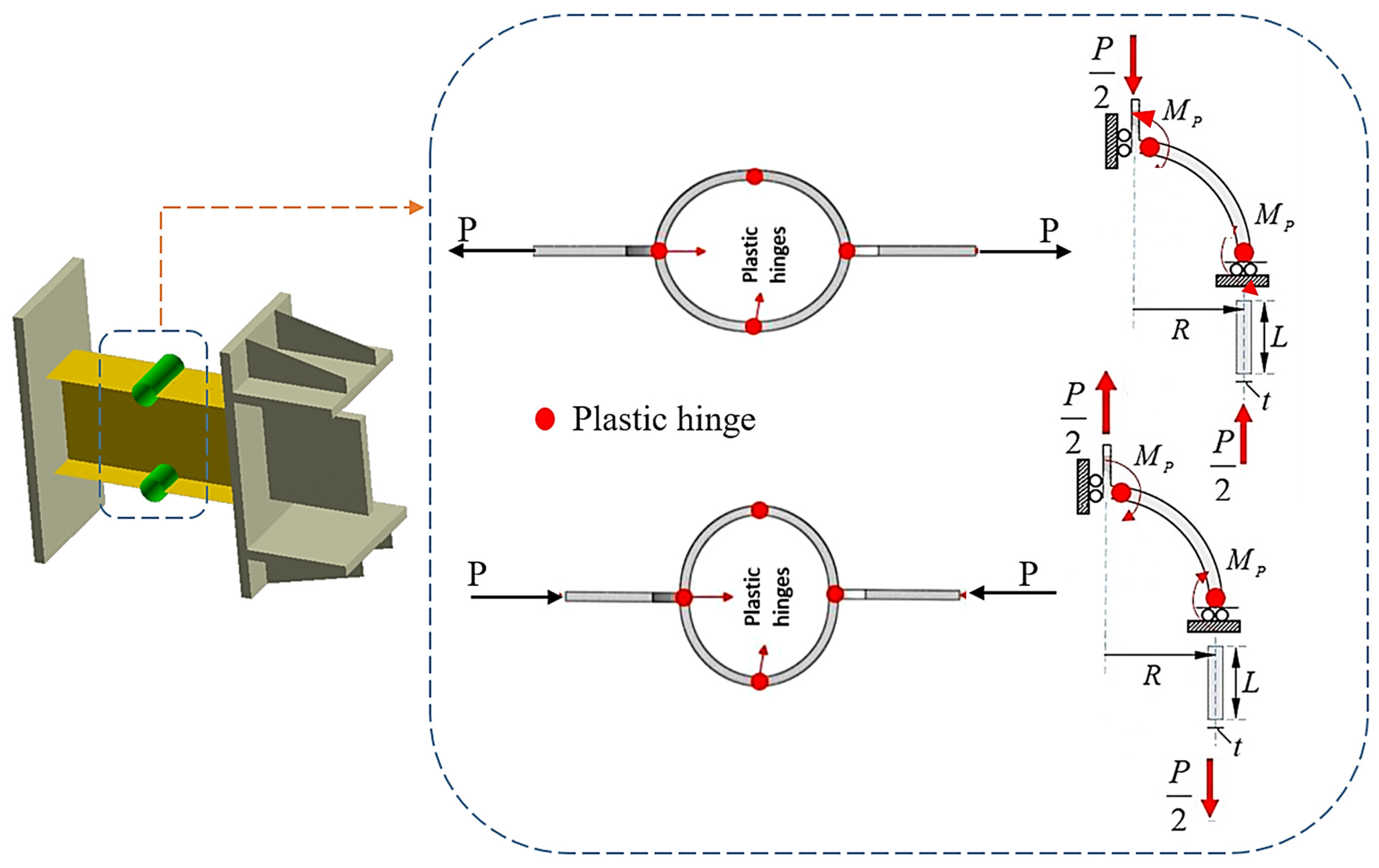
The bending moment of the replaceable ductile steel link imposes tension and compressive force, P , on the two sides of the ductile steel link, which causes four plastic hinges in the pipe elements [24] as illustrated in Figure 3.
The relationships between the strength of material, variation of the ductile steel link radius, R, and its internal forces in the elastic zone under load P are shown in Figure 3. Moreover, according to Castigliano’s second theorem [25], δ y = U / V , δ x = U / H , and θ = U / M 0 , where U is the complementary energy of flexure, V is the vertical force, H is the horizontal force, θ is the rotation of the upper end, and M0 represents two different variables: M + = 0.318 P R , which is the bending moment at θ = π 2 , and M = 0.182 , which is the bending moment at θ = 0 . Accordingly, by calculating the horizontal ( δ x ) and vertical ( δ y ) displacements of the pipe section end, respectively, as δ y = 0.149 P R 3 E I and δ x = + 0.137 P R 3 E I , as well as the forces of axial force of T = 1 2 P cos θ and shear forces of V = 1 2 P sin θ , the P is determined as follows. In the mentioned equation, the moment of inertia of the pipe elements is calculated as I = t p 3 L 12 where t p and L are the thickness and width of the ductile pipe section, respectively.
Four plastic hinges ( M p , p i p e ) are formed in the ductile steel link, as shown in Figure 3. To impose the plastic hinge formation in the pipe element before yielding of the ductile steel link, Equation (3) must be satisfied. This equation has been derived based on the assumption that the stability equation gives the 2 M p , p i p e = P R 2 and knowing M p , p i p e = t p 2 L F y 4 , where L is the length of the pipe element.
P = M p d M p t p 2 L F y d R
In this equation, M p and d are the plastic flexural capacity and depth of the replaceable steel link without considering the ductile pipe element. As observed, the bearing load capacity of the ductile steel link is directly correlated with its length (that is equal to the flange width of the replaceable steel link, b f ), yielding stress, and ductile pipe element thickness squared and the ratio of t p t f . Accordingly, in this paper, the normalized t p t f is considered.

3. Method of Study

To maintain the elasticity of GFRP components and confine the yielding through the ductile pipe elements, a parametric study was conducted to achieve the optimum configuration. To do so, first, a conventional I-shaped steel link was designed and analyzed. For this model, an I-shaped steel link with a depth of d = 244   m m , width of b f = 144   m m , flange thickness of t f = 16   m m , and web thickness of t w = 10   m m was used. The M p of the models was measured as 127.8 MPa. Accordingly, to achieve ψ = 0.9 , H-shaped pultruded GFRP profile sections with depth, d = 340   m m , flange wide, b f = 300   m m , and thickness (for flanges and web) of 18 mm were used; the section was determined according to the production of a company (https://fiberprofil.com/en/products/fiberglass-reinforced-profiles/i-beams, accessed on 1 June 2026). The H-shaped GFRP section model was kept for all models. Then, keeping the designed sections, the pipe section was added to the middle of the ductile I-shaped steel link. The diameter of the pipe elements was selected as d/4 = 60 mm. The thickness, t p , of the ductile pipe elements was considered as t p = 0.5 t f , 0.75 t f , 1.0 t f , 1.25 t f , 1.5 t f and 2.0 t f where t f is the flange thickness of steel link. For all models, the link length of e = 500   m m was used. Subsequently, variable β was defined as t p t f to consider the optimum ratio of t p to t f . Hence, in the next sections, a name is designed for each model where I represents the system with a conventional I-shape without a pipe element, and models featuring a ductile pipe section are defined by β.

4. Numerical Study

4.1. Simulation of FE Models

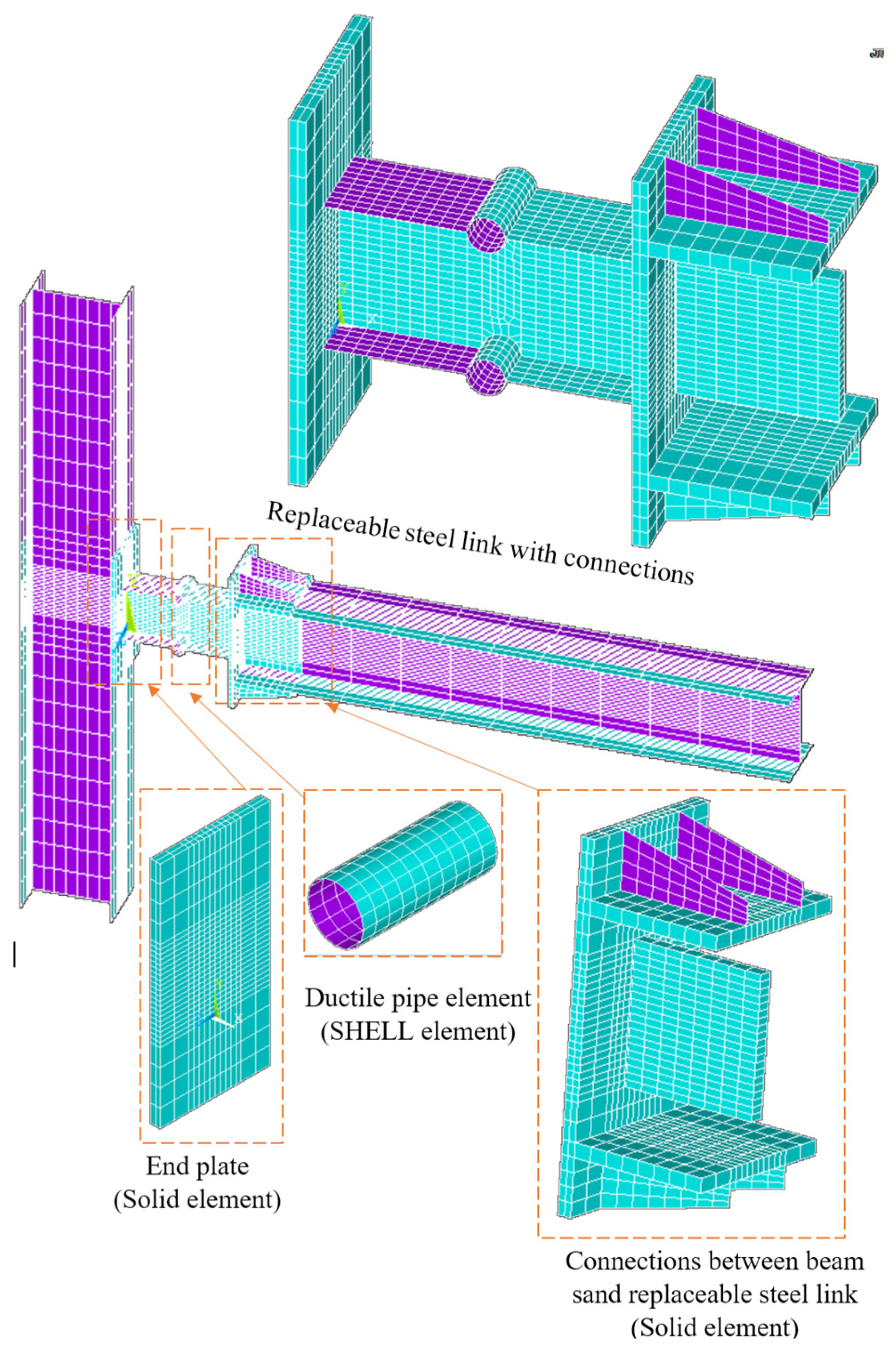
To conduct the finite element (FE) analysis of the models, ANSYS 2021 R2 software was used. Although all components can be modeled using solid elements, doing so significantly increases the computational time. Since through-thickness stress evaluation is not required, the GFRP members, pipe elements, and steel link were modeled using shell elements (SHELL281). Only the connecting plates, including the top and bottom plates, shear plate, and the end plates, were modeled with solid elements (SOLID186). Also, since it is expected that the bolts will not fracture, they were simulated by the BEAM188 element, where this element can capture the nonlinear response. These elements are capable of accounting for yielding, buckling, and large deformation. The mesh size was selected in such a way that, in the locations with the possibility of yielding, a smaller mesh size was used than in the expected elastic zones. Accordingly, 28,769 elements were utilized for the simulation of each model; the schematic view of the meshing of the models is shown in Figure 4. During the analysis of the models, an imperfection was applied to the models to account for geometric nonlinearity. To do so, first, a buckling analysis was performed. Then, the buckled shape of each model based on the first buckling mode was imported to the software, considering a coefficient of 0.001 to account for the imperfection.
To model damage in ANSYS, the Hashin Failure Criterion was used. It is available in ANSYS Composite PrepPost (ACP) and in certain composite material models. This criterion, specifically developed for fiber-reinforced composites (e.g., GFRP and CFRP), separately predicts fiber tension failure, fiber compression failure, matrix tension failure, and matrix compression failure.

4.2. Boundary Conditions and Materials

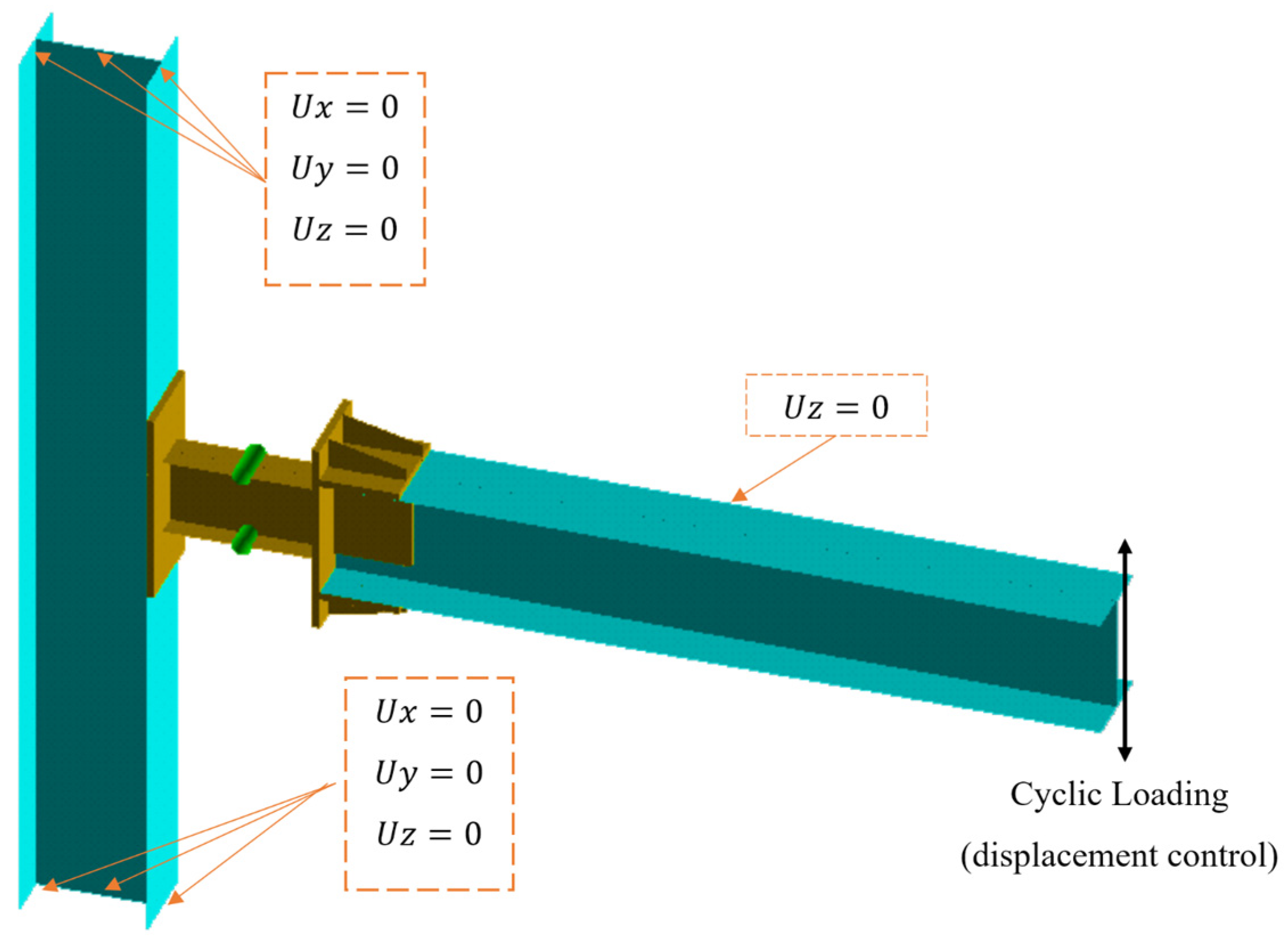
Under lateral loading, inflection points in MRF systems are located at the middle of beams and columns, and the boundary conditions, as illustrated in Figure 5, were used. The two ends of the columns were restricted to deflection and free to rotate to achieve the zero-bending moment. In practical projects, the floor beam burden through the floor, also known as out-of-plane displacement, is restricted. Also, cyclic loading was applied to the end of the beam. The loading protocol monitored a displacement-controlled loading as y , 2 y , 3 y , 4 , where y represents the yield displacement of the system. The yield displacement is determined as the starting yield through the model. Accordingly, for each model, first a monotonic analysis was carried out to measure the y , then analysis of the models under cyclic loading was completed based on the mentioned loading protocol. This sequence was repeated in both positive and negative directions until a maximum interstory drift corresponding to a beam-end rotation of 0.04 radians was achieved, in accordance with established seismic testing protocols (e.g., AISC 341 or FEMA 461). Each displacement level was cycled three times to capture stiffness degradation, pinching behavior, and cumulative damage effects.
Material properties for the GFRP components are listed in Table 1. For the Pultex® SuperStructural 1525 series profiles, the finite element (FE) models utilized orthotropic elastic properties, defined by a tensile strength of 300 MPa and a modulus of elasticity of 70 GPa. These GFRP components were modeled as linear-elastic, and damage initiation was evaluated using the Hashin failure criterion. For the steel components, the A36 steel was assigned a modulus of elasticity of 200 GPa, and yield and ultimate strengths of 240 MPa and 370 MPa, respectively.

4.3. Verification of FE Simulation

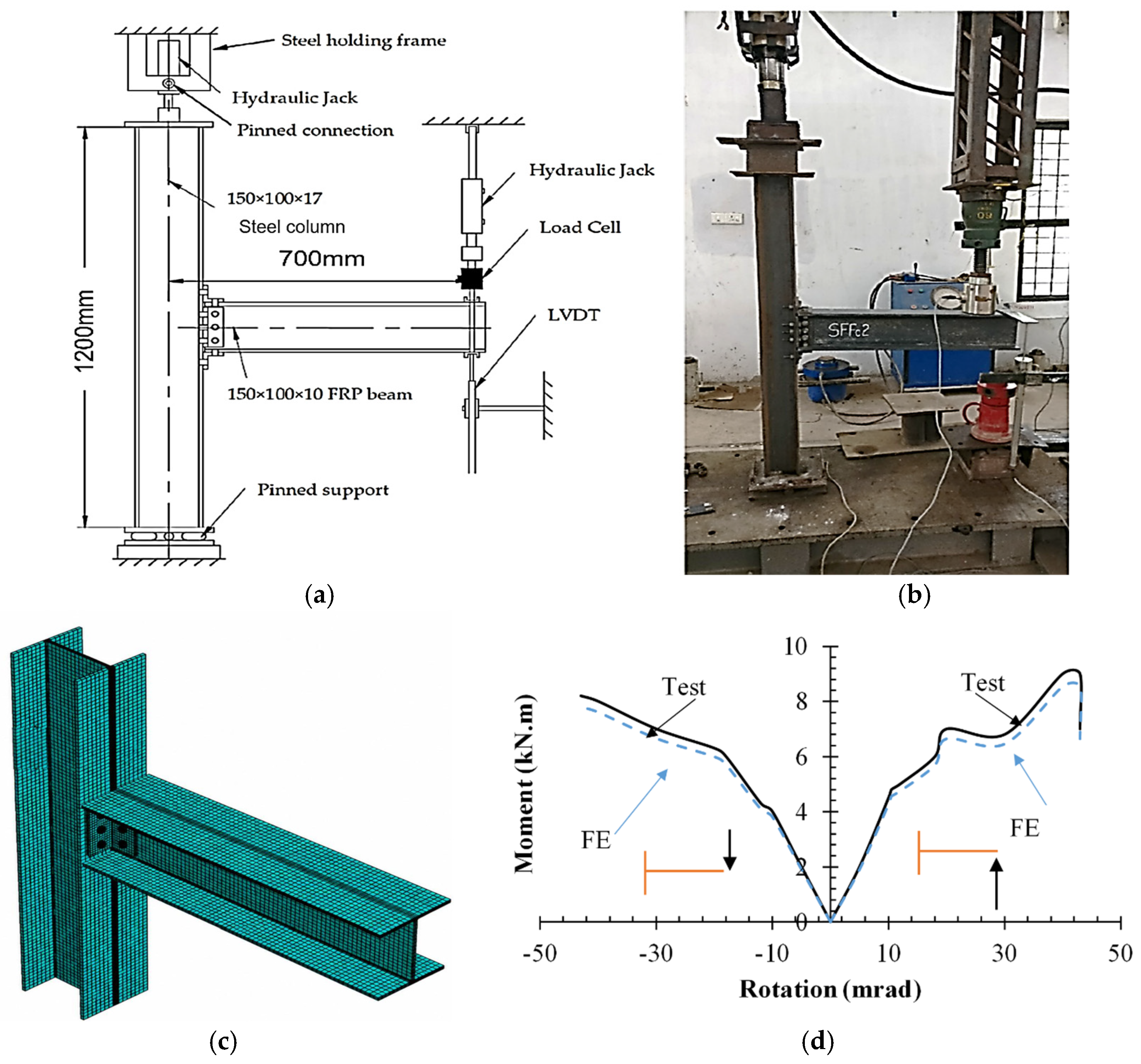
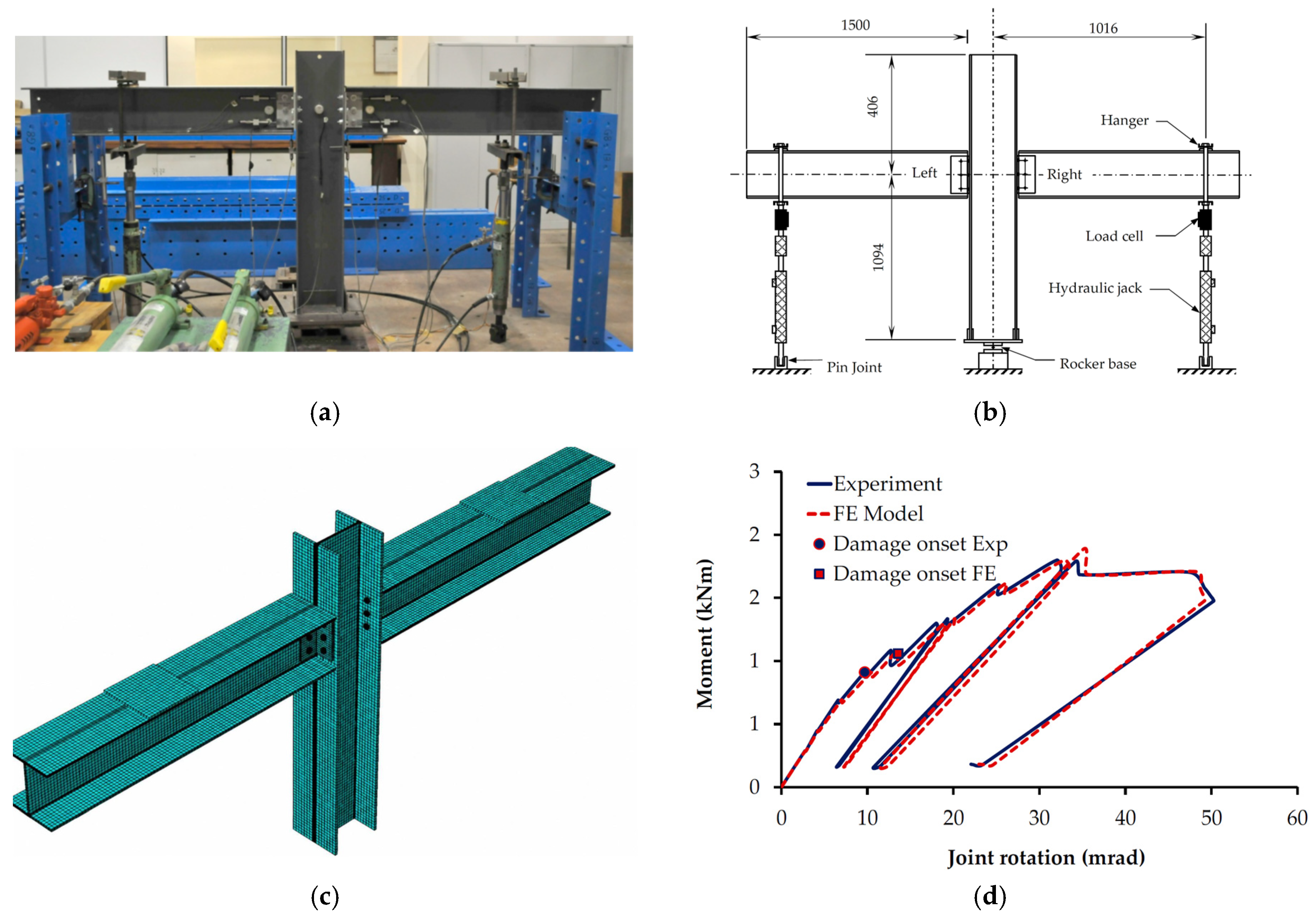
To verify the accuracy of the FE modeling approach, two experimental studies conducted by Qureshi et al., as reported in [26] under monotonic loading (Figure 6) and as reported in [27,28] under cyclic loading (Figure 7), were selected, as their configuration closely resembles the connection system investigated in the present paper. The referenced tests involved GFRP beams and columns connected using steel components, making them highly relevant, although not identical, to the connection system examined in this study. All material properties, including the elastic moduli, shear moduli, and strength parameters for both GFRP and steel components, were input into the FE software ANSYS 2021 R2 in strict accordance with the experimental data reported in the cited studies. Likewise, the boundary conditions, such as support restraints and loading application points, were replicated precisely to reproduce the physical test setups. At the two ends of columns for both tests, the displacements were restrained, where their free rotation was applied to create a simple connection. In Figure 6, the curve on the left corresponds to upward loading, which induces a positive moment at the support, while the curve on the right represents downward loading, resulting in a negative (hogging) moment. Within the linear elastic range, the FE and experimental curves are in close agreement, with discrepancies of less than 2%. In the nonlinear range, where material degradation and local buckling may occur, the maximum deviation is approximately 7%, a margin widely regarded as acceptable in structural simulations of composite systems. Correspondingly, in Figure 7, there is around 2% error in linear zones, whereas the differences between the FE results and experimental results in the nonlinear zone are less than 6%. These comparative analyses reveal suitable agreement between the numerical predictions and experimental measurements.

5. Discussion and Results

5.1. Hysteresis Curves

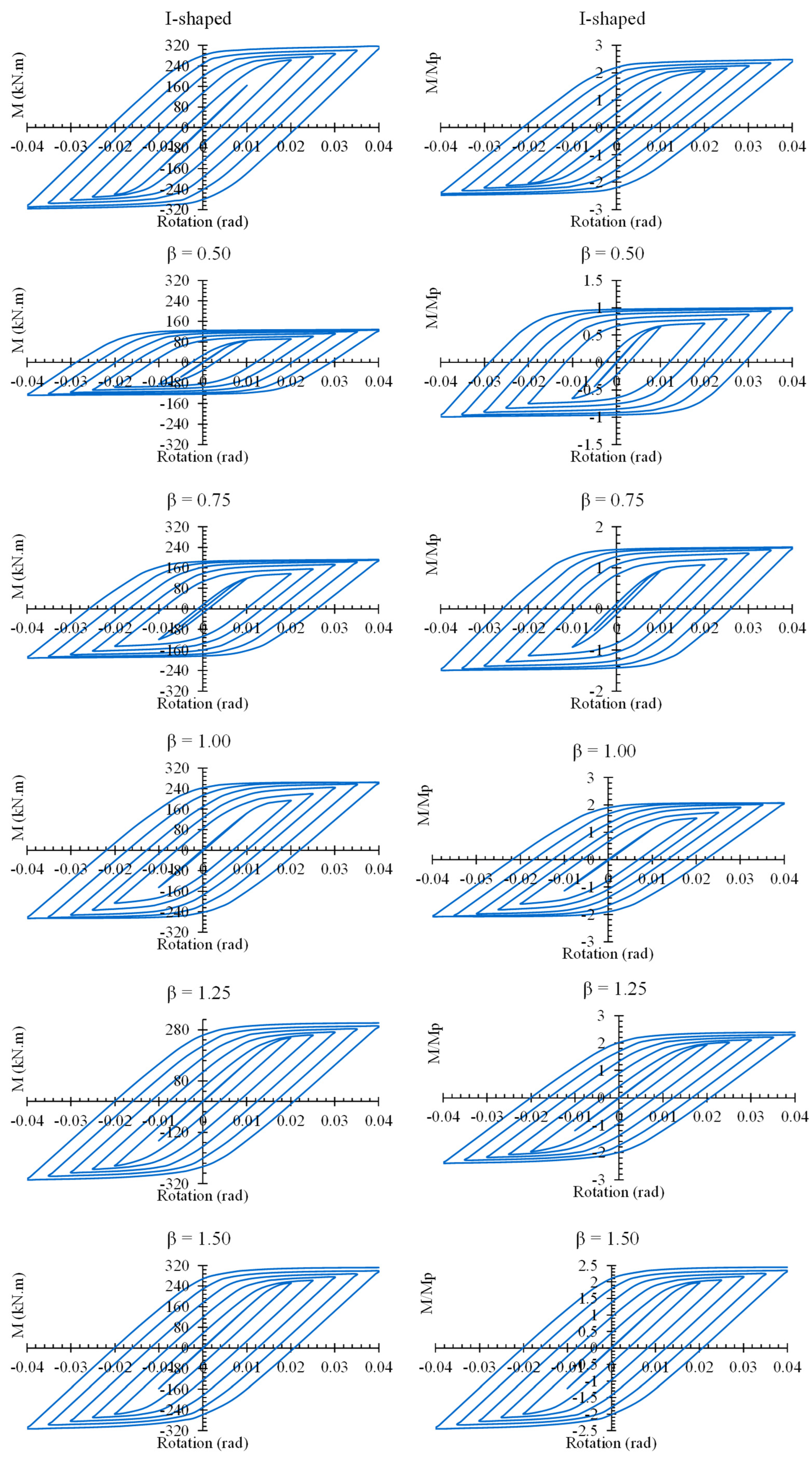
As valuable information regarding the response of any structure is extracted by hysteresis curves, in Figure 8, the hysteresis curves of the analyzed FE models are plotted. As revealed in this figure, the models featuring replaceable steel links with or without a ductile pipe element exhibited stable hysteresis loops without any degradation in strength, stiffness, and energy dissipation. This finding confirms that ductile behavior governs the system response. Comparing the curves also shows that, by increasing β , the hysteresis curves tend to enhance, qualifying the enhancement to guarantee suitable performance, while the plastic hinge formation is confined through the ductile pipe element as well as the replaceable steel link that is considered in the next sections. The capacity of the models with β = 0.5 reaches around 1.0, whereas by increasing β , it rises to around 3.0.

5.2. Monotonic Response

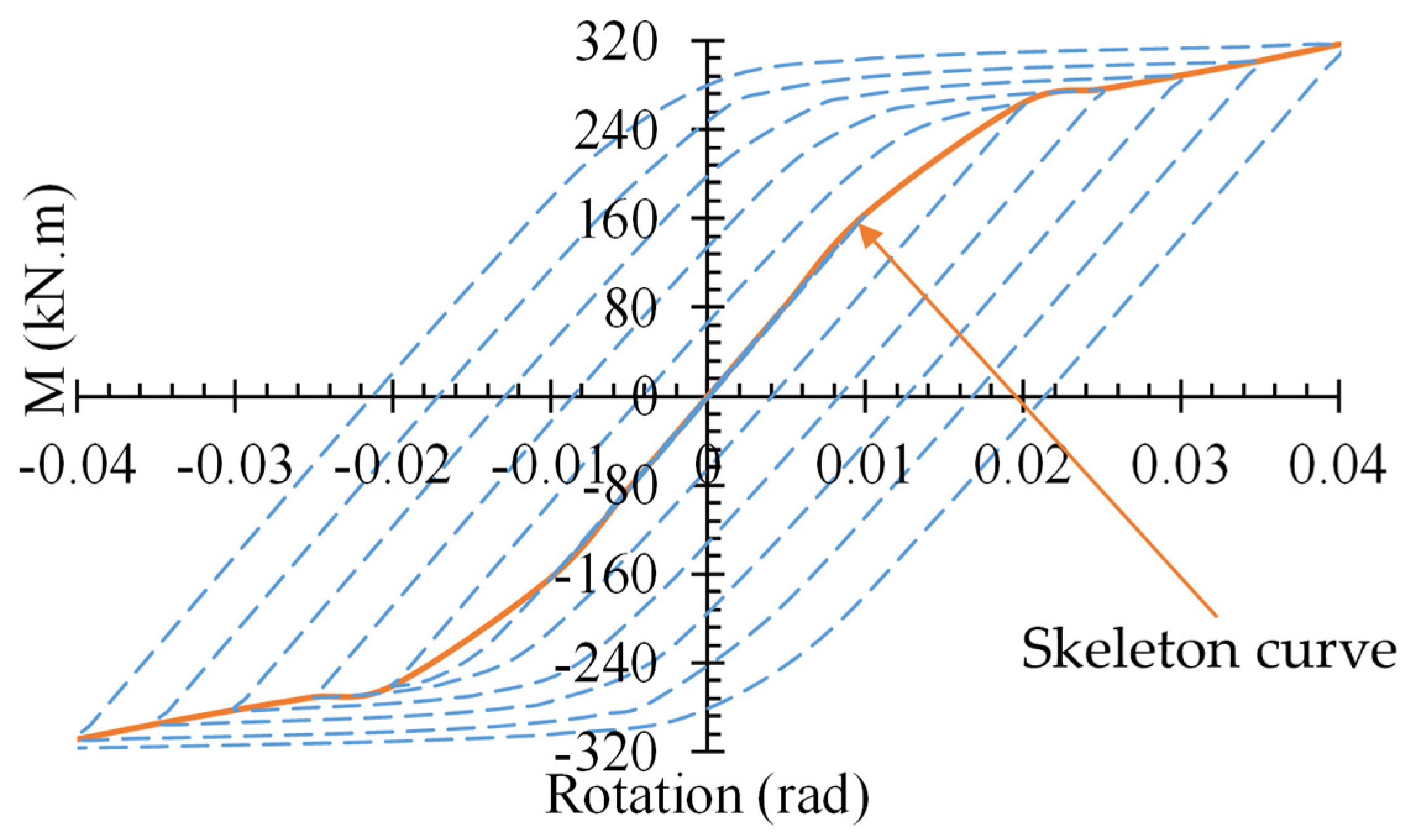
To have a better comparison of the results, the skeleton curves of the FE models were compared. The skeleton curves of each model were extracted as illustrated in Figure 9. Since symmetrical hysteresis curves were obtained for the FE models, the skeleton curves are helpful to consider the behavior of the system. Utilizing these curves, the structural parameters are easier to extract than hysteresis curves.
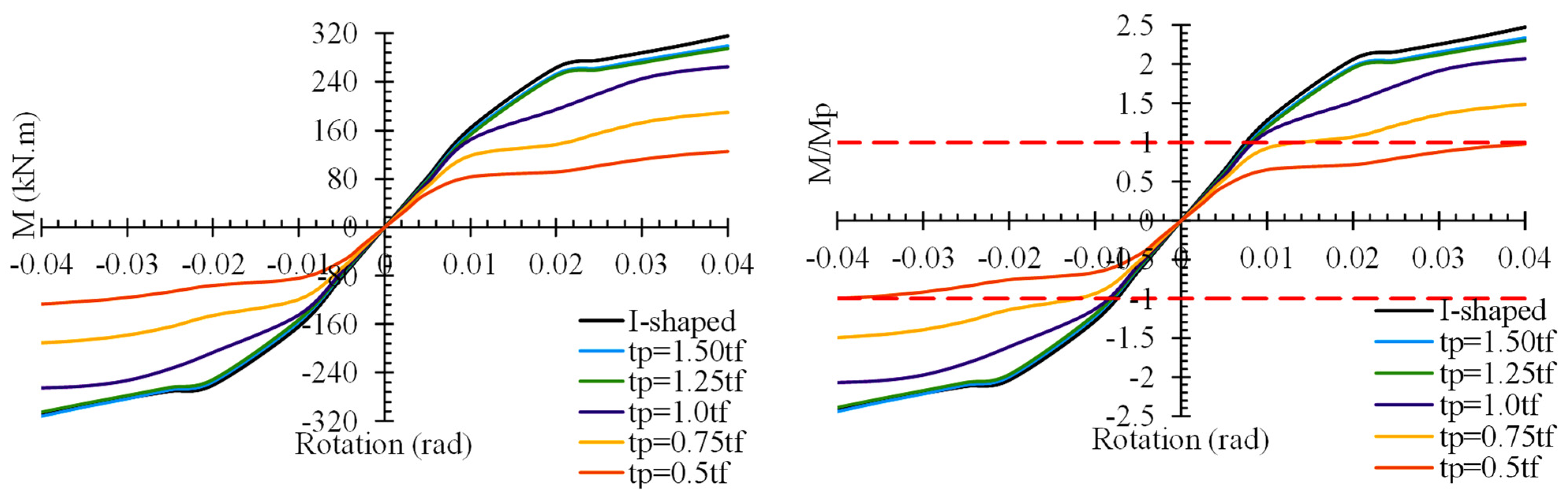
Referring to Figure 10, by increasing β , the response of the system is closer to the hybrid system featuring an I-shaped replaceable link. A notable finding is that, for all systems, the nonlinear behavior of each system commences around a rotation of 0.01 rad. After yielding, the strength of the system not only dropped but also tended to rise, but with a different rate related to β . For the models with β < 1 and β 1 , the slope of the response represents the rate of strength enhancement after yielding began, which is different. For the models of β < 1 after yielding emerged through the models, the rise was less than that of models with β 1 . For the models, the slope of strength is divided into three ranges: rotation < 0.01 rad, 0.01 < rotation < 0.02 rad, and rotation > 0.02 rad. During rotation greater than 0.02 rad, the slope of the skeleton curves tends towards zero in systems with β < 1 around rotation 0.02 rad. Accordingly, it is recommended not to use models with β < 1 . Referring to the curves of M/Mp versus rotation indicates that the flexural capacity of only model β = 0.5 reached Mp at the end of loading. For models of β 1 , M/Mp = 1 was achieved around a rotation of 0.01 rad.

5.3. Structural Parameters

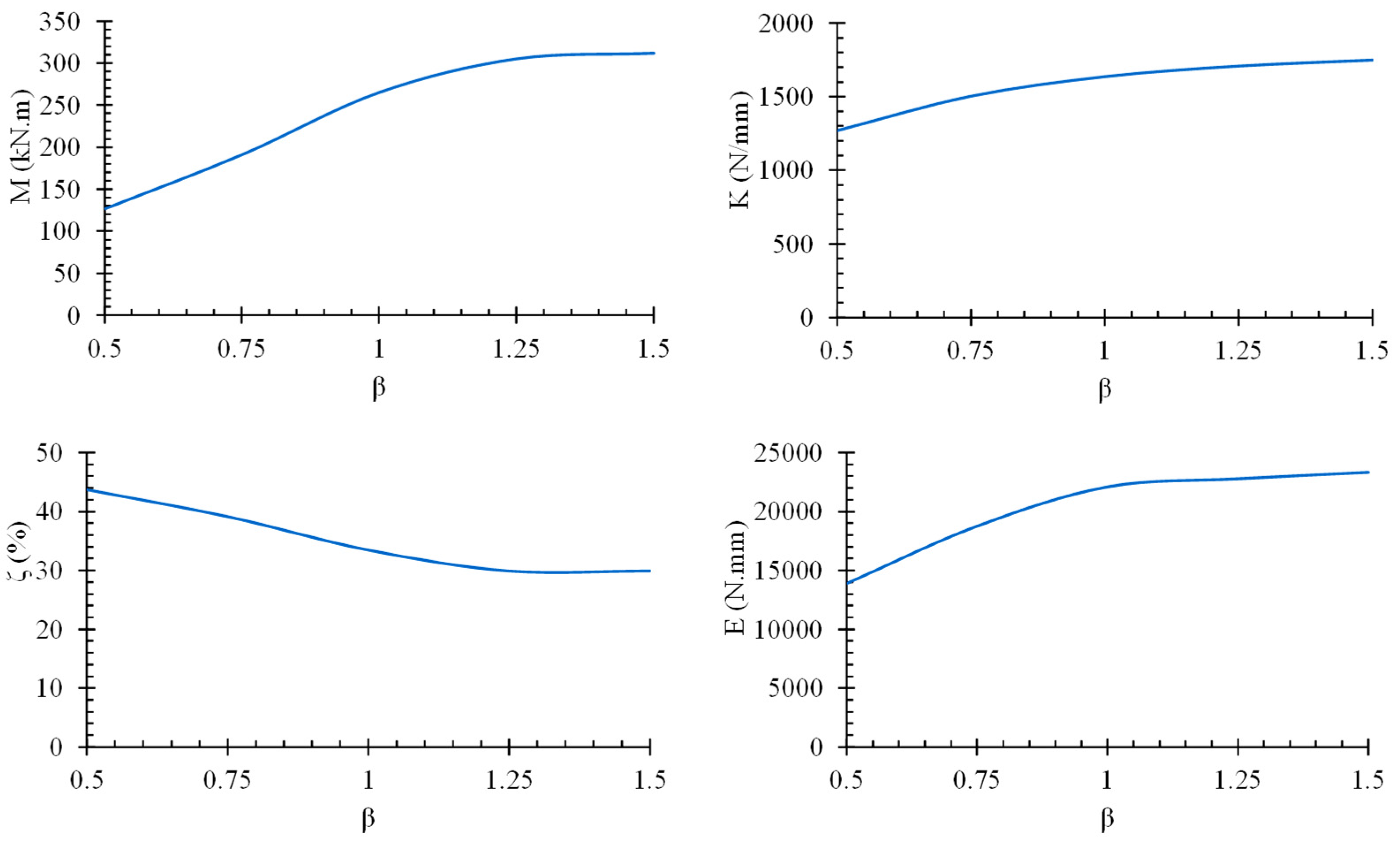
Plotting the structural parameters, including bending moment capacity, M, elastic stiffness, K, energy dissipation, E, and equivalent damping ratio, ζ, of the FE models versus β (Figure 11) shows that by increasing β , the values of M, K, and E tend to increase and ζ tends to decrease. However, at β = 1 , the rate of the structural parameters is seen. To do so, the results are listed and compared in Table 2. Comparing the results indicates that adding the ductile pipe element reduced M, K, and E but changed the ζ related to β . Adding the pipe with β = 0.5 reduced M, K, and E by 60%, 31%, and 45%, respectively, whereas it increased ζ by 36%. However, when the system with β = 1 is used, an M, K, and E of 16%, 11%, and 12%, respectively, and an enhancement of 4% in ζ were obtained. Also, utilizing β > 1 , a close response with ignorable reduction in M (1% to 3%, K (5% to 7%), and E (7% to 9%) is revealed, but the ζ was also reduced by 7%. Considering the results as well as the yielding distribution, utilizing a system with β 1 , where the thickness of pipe elements equals the flange thickness of the replaceable steel link, is strongly recommended.
Also, by changing β = 0.50 to β = 0.75 , β = 1.00 , β = 1.25 , and β = 1.50 , the values of M, K, and E were enhanced by 1.51 times to 2.46 times, 1.18 times to 1.38 times, and 1.35 times to 1.68 times, respectively, whereas ζ was reduced by 10% to 32%. Accordingly, it is indicated that M, E, K, and ζ are related to β .

5.4. Distribution of Stress Through the Components

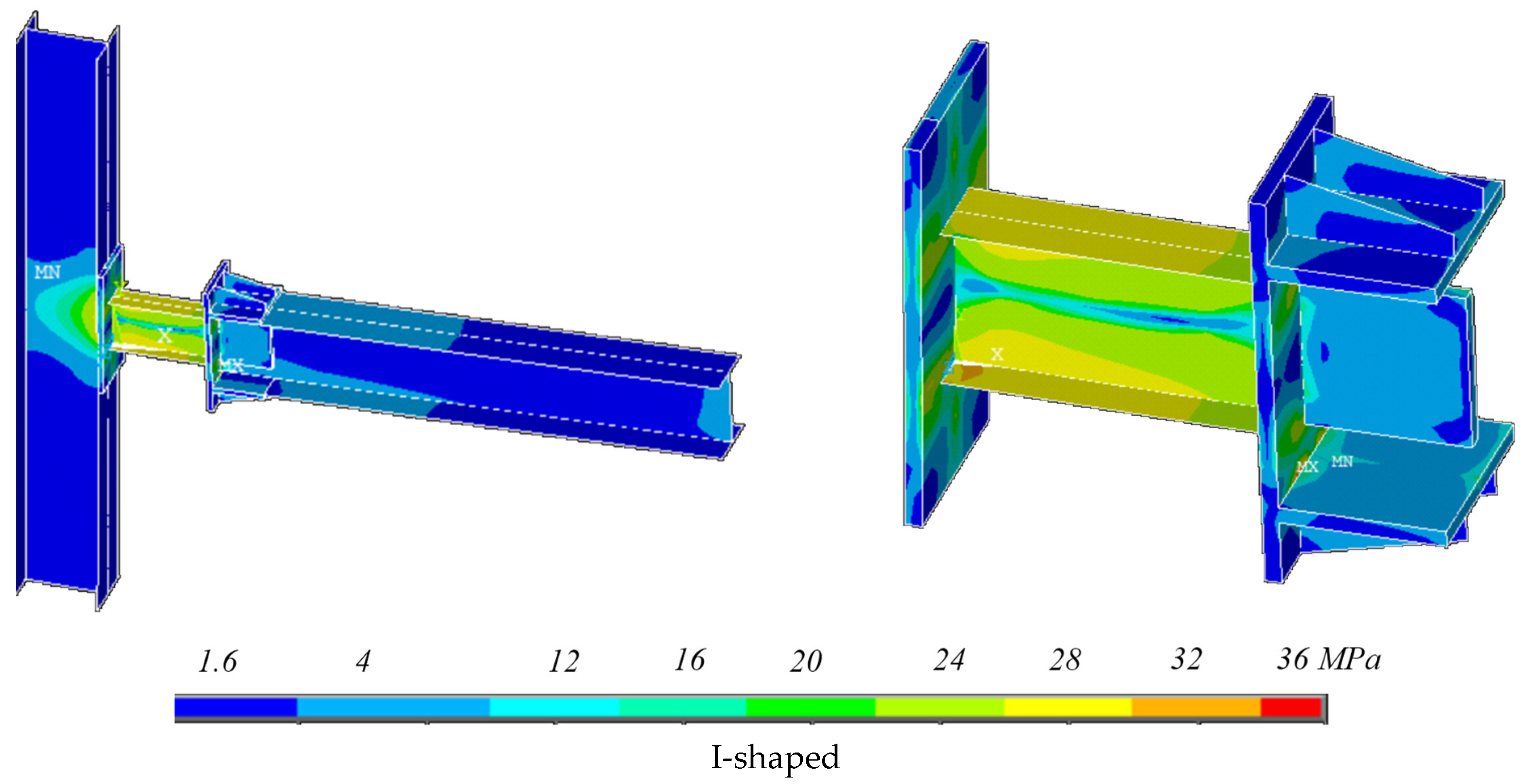
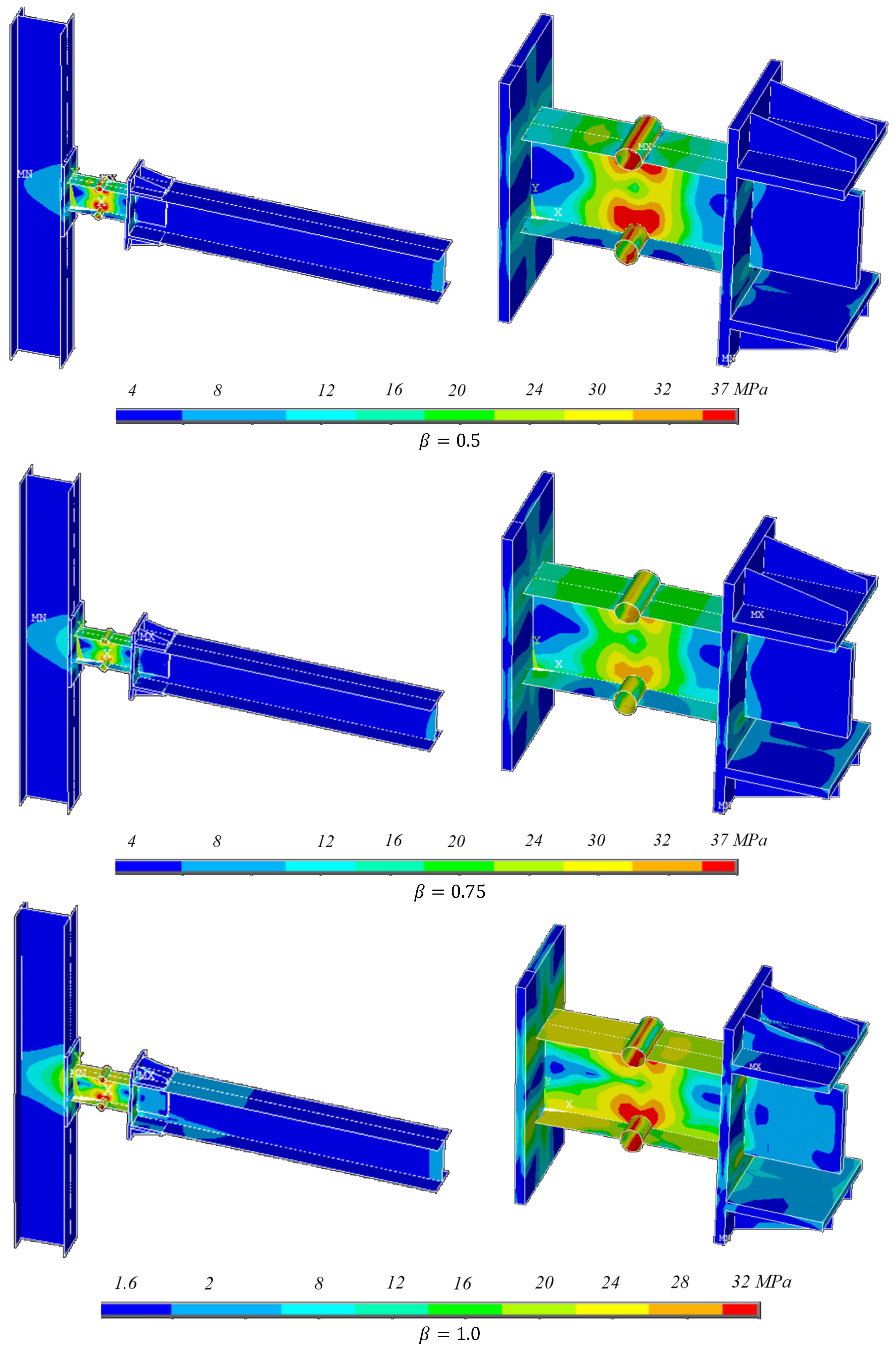
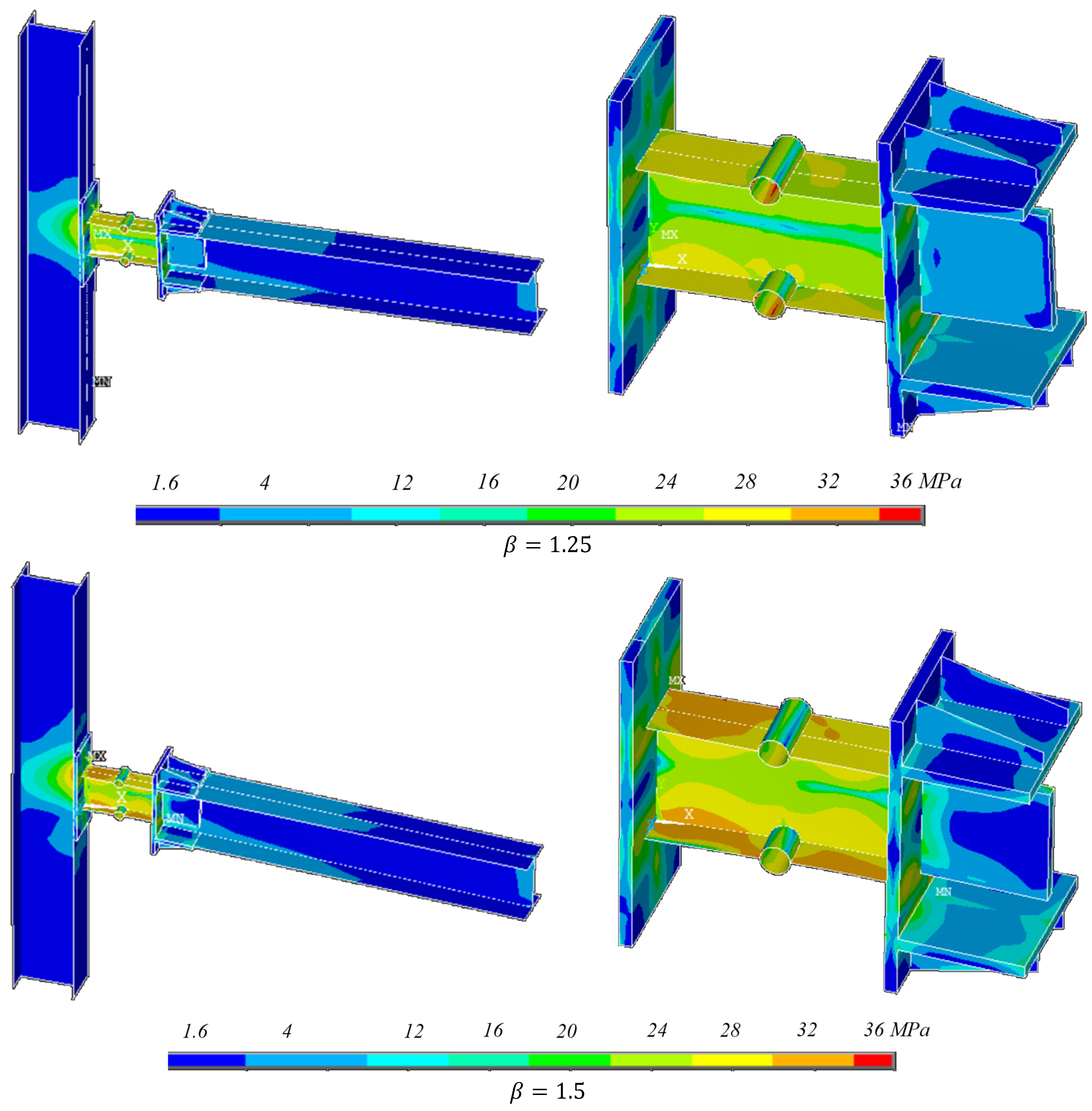
One of the main features of using the replaceable steel link equipped with the ductile pipe section is confining damage in predictable locations. In other words, a primary advantage of integrating a replaceable steel link equipped with a ductile pipe section is the ability to concentrate structural damage within predictable, controlled locations. Figure 12 illustrates the stress states of the models, confirming that the connections maintained elastic behavior throughout the loading history. While the glass fiber-reinforced polymer (GFRP) components also remained within the elastic range, the models with capacity ratios of β = 1.25 and β = 1.50 demonstrate that the panel zone stresses approached the ultimate capacity of the GFRP material. Conversely, the inclusion of the pipe element successfully localized yielding to the pipe section and the adjacent web of the steel I-shaped link; this is a highly desirable performance characteristic, as it effectively shields the GFRP beams and columns from excessive stress provided that β 1.0 . Consequently, systems designed with β 1.0 utilize the pipe section as a sacrificial ductile fuse, ensuring the robust protection of the primary structural members.
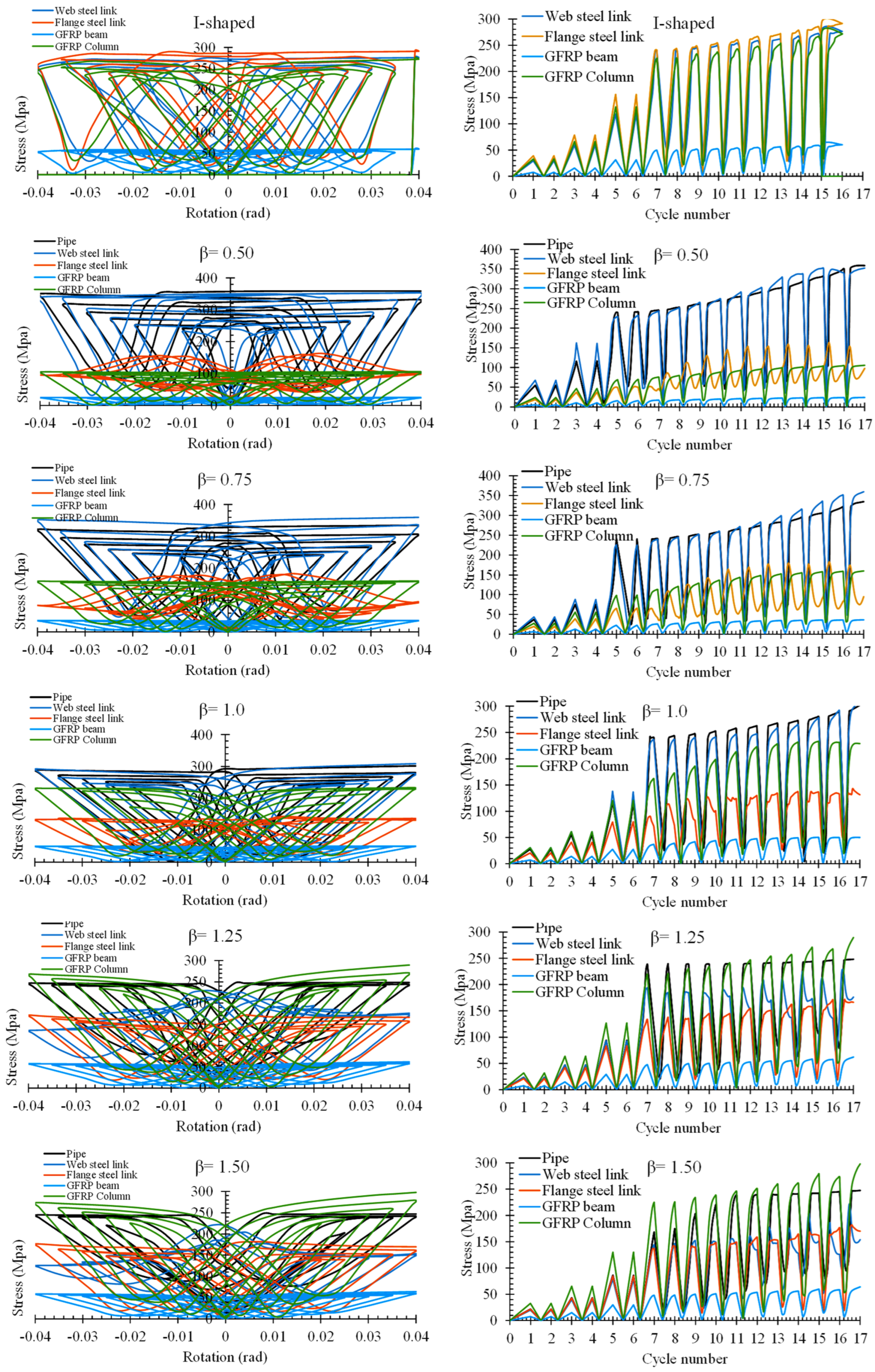
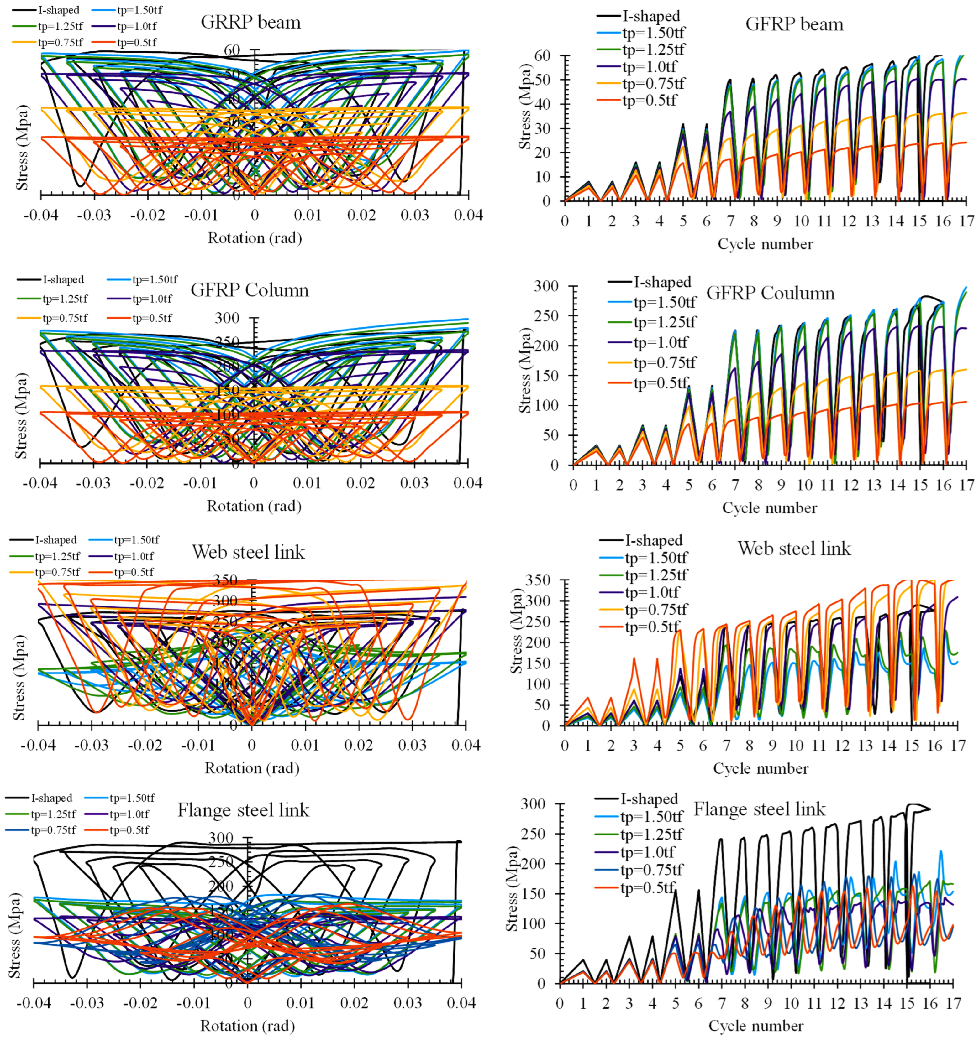
Further insights are provided in Figure 13 and Figure 14, which track the von Mises stress of individual components relative to rotation and cycle number. A notable transition in stress behavior occurred across all components at a rotation of approximately 0.01 radians; this inflection point marks the onset of yielding in specific elements, which subsequently triggers a redistribution of internal forces throughout the entire system. A comparative analysis of the I-shaped link versus the enhanced configuration, the link augmented with the ductile pipe section, reveals that the most significant stress reductions occurred in the steel link flanges. By incorporating the ductile pipe fuse, the overall stress demand is substantially mitigated, validating the efficacy of this hybrid system in enhancing structural resilience.
The maximum stress in each component is listed in Table 3. As found in this table, by adding the pipe element to the I-shaped steel link, the stress of the web of the I-shaped steel link is increased while β 1.0 , as expected. In contrast, the stress of the flange of the I-shaped steel link, the GFRP beams, and the GFRP columns were reduced by 46% to 51%, 17% to 60%, and 15% to 40%, respectively. However, while β > 1.0 , not only were the stresses in the GFRP components not reduced, but they were also increased by 1% to 9%, which is ignorable. More importantly, the noticeable finding is that by β > 1.0 , the stress in the GFRP element is not reduced as expected. Therefore, it is not recommended to use β > 1.0 .

6. Conclusions

In this paper, an innovative hybrid moment-resisting frame composed of GFRP profile sections for beams and columns with a replaceable steel link equipped with ductile pipe elements was studied parametrically and numerically. Accordingly, the findings are summarized as follows:
-
The system response is governed by ductile behavior, with hysteresis curves improving as β (the ratio of pipe thickness to the flange thickness of the steel link) increases. Increasing β also raises the capacity from approximately 1.0 for β = 0.5 to about 3.0 for higher β values. This enhancement ensures suitable performance provided that plastic hinge formation remains confined to the ductile pipe element and replaceable steel link, as discussed in subsequent sections.
-
A key advantage of the replaceable steel link with a ductile pipe section is its ability to confine damage to predictable, controlled locations, though panel zone stresses in models with β = 1.25 and 1.50 approach the GFRP’s ultimate capacity. For β ≤ 1.0, yielding is successfully localized to the pipe and steel link web, acting as a sacrificial fuse, thereby protecting GFRP beams and columns from excessive stress.
-
For all systems, nonlinear behavior initiates around a rotation of 0.01 rad, after which strength does not drop but increases at a rate dependent on β. Models with β < 1 exhibit slower post-yield strength gain and reach zero stiffness near 0.02 rad, whereas models with β ≥ 1 show steeper hardening and achieve M/Mp = 1 at approximately 0.01 rad, except for β = 0.5, which only reaches full plastic moment (Mp) at the end of loading. Consequently, using β < 1 is not recommended due to limited post-yield performance.
-
Adding the pipe element to the I-shaped steel link increases web stress when β ≤ 1.0 (leading to web yielding), while stresses in the flange, GFRP beam, and GFRP columns reduce by 46–51%, 17–60%, and 15–40%, respectively. However, for β > 1.0, stresses in GFRP components are not reduced but slightly increase by 1–9% (negligible), making β > 1.0 not recommended.
-
Recommendation for future work: The present study focuses on the behavior and performance of the proposed beam-to-column connection. To further validate its applicability in practical structural systems, future research should investigate the performance of the proposed connection in multi-story GFRP frame structures subjected to both gravity and seismic loading. In addition, comprehensive nonlinear analyses should be conducted to determine the seismic design parameters, including the response modification factor (R), overstrength factor (Ω), and displacement amplification factor (Cd) in accordance with performance-based seismic design provisions. Finally, the seismic behavior of the proposed hybrid GFRP–steel system should be systematically compared with that of conventional steel moment-resisting frames to evaluate its structural efficiency, energy dissipation capacity, ductility, damage distribution, overall seismic performance, and economic aspects.

Author Contributions

Conceptualization, A.G.; methodology, D.-P.N.K. and A.G.; software, A.G.; validation, R.S., D.-P.N.K. and A.G.; formal analysis, R.S. and A.G.; investigation, D.-P.N.K. and A.G.; resources, R.S. and D.-P.N.K.; data curation, D.-P.N.K.; writing—original draft preparation, R.S. and A.G.; writing—review and editing, D.-P.N.K.; visualization, R.S. and A.G.; supervision, D.-P.N.K. and A.G.; project administration, R.S., D.-P.N.K. and A.G. All authors have read and agreed to the published version of the manuscript.

Funding

The project was partially or fully supported by Walailak University.

Data Availability Statement

The original contributions presented in this study are included in the article. Further inquiries can be directed to the corresponding author.

Acknowledgments

The authors appreciate the support of Walailak University to complete the paper.

Conflicts of Interest

The authors declare no conflicts of interest.

References

  1. Adel, K.; Abdelazeem, M.; Sherif, A.; Saadeldin, M.; Rashed, H.; Omran, M.M.; Tawfik, N.M. Strengthening RC beams and columns with CFRP, GFRP and KFRP laminates. Sci. Rep. 2026, 16, 11004. [Google Scholar] [CrossRef] [PubMed]
  2. Dehshirizadeh, M.; Eslami, A.; Sar-Yazdi, M.K.; Ronagh, H.R. Pultruded GFRP box beams: State-of-the-art review on constituents and structural behavior. Struct. Eng. Mech. 2024, 90, 127–142. [Google Scholar] [CrossRef]
  3. Haw Shin, Y.; Yee Yoong, Y.; Hejazi, F.; Raizal Saifulnaz, M.R. Review on pultruded FRP structural design for building construction. IOP Conf. Ser. Earth Environ. Sci. 2019, 357, 012006. [Google Scholar] [CrossRef]
  4. Soumbourou, M.A.; Aksoylu, C.; Madenci, E.; Özkılıç, Y.O. Web Crippling of Pultruded GFRP Profiles: A Review of Experimental, Numerical, and Theoretical Analyses. Polymers 2025, 17, 2746. [Google Scholar] [CrossRef] [PubMed]
  5. Alshimmeri, A.J.; Kontoni, D.-P.N.; Ghamari, A. Improving the seismic performance of reinforced concrete frames using an innovative metallic-shear damper. Comput. Concr. 2021, 28, 275–287. [Google Scholar] [CrossRef]
  6. Kontoni, D.-P.N.; Ghamari, A. A Numerical and Parametric Study on Metallic Double Corrugated Damper Directly Connected to CBF Braces. Struct. Des. Tall Spec. Build. 2025, 34, e2213. [Google Scholar] [CrossRef]
  7. Thongchom, C.; Ghamari, A.; Kontoni, D.-P.N. Post-Fire Performance Evaluation of an Innovative Trapezoidal Shear Damper for Enhancing the Behavior of Concentrically Braced Frames. Struct. Eng. Mech. 2025, 96, 167–182. [Google Scholar] [CrossRef]
  8. Al-Ezzi, M.J.; Ayamsir, A.; Supian, A.B.M.; Beddu, S.; Al-Dalaien, R.N. Flexural Behavior and Failure Modes of Pultruded GFRP Tube Concrete-Filled Composite Beams: A Review of Experimental and Numerical Studies. Buildings 2024, 14, 3966. [Google Scholar] [CrossRef]
  9. Khalil, M.; Abdel-Rahman, M.; Shoeib Soliman, A.E.; Sheriff, A.G.; Salem, M.M. Experimental and theoretical study of used GFRP I-profile composite columns. Fract. Struct. Integr. 2025, 19, 263–279. [Google Scholar] [CrossRef]
  10. Aktepe, R.; Akduman, S.; Aldemir, A. Enhanced structural performance of pultruded GFRP trusses: Experimental and numerical insights. Eng. Struct. 2025, 343, 121070. [Google Scholar] [CrossRef]
  11. Lee, S.-Y. Fatigue Behaviors of High-Speed Track Slabs Reinforced by GFRP Composite Rebar: Full-Scale Experimental Verification. J. Compos. Sci. 2025, 9, 597. [Google Scholar] [CrossRef]
  12. Aripov, D.; Kuznetsov, I.; Salakhutdinov, M. Experimental investigation of pultruded GFRP connections. E3S Web Conf. 2021, 274, 03013. [Google Scholar] [CrossRef]
  13. Pirchio, D.; Althouse, J.A.; Madlem, T.A.; Denavit, M.D.; De Caso y Basalo, F.J.; Busel, J.P.; Kurama, Y.C.; Walsh, K.Q. Assessment of Resistance Factors for LRFD of Steel Bolted Connections in Pultruded FRP Frames. J. Compos. Constr. 2024, 28, 04024001. [Google Scholar] [CrossRef]
  14. Mathew, A.; Gonilha, J.A.; Nadir, Y.; Ye, Y. Exterior weak-axis beam-to-column bolted connections between GFRP I-shaped pultruded profiles using stainless steel cleats. Eng. Struct. 2024, 314, 118366. [Google Scholar] [CrossRef]
  15. Tang, J.; Feng, P.; Wang, Q. Beam-column joints of FRP pultruded profiles: State-of-the-art review, performance evaluation, and design method. Compos. Struct. 2025, 370, 119250. [Google Scholar] [CrossRef]
  16. Zhang, Z.; Wu, C.; Nie, X.; Bai, Y.; Zhu, L. Connections of Fibre Reinforced Polymer to Steel Members: Numerical Modelling. In Composites for Building Assembly; Springer Tracts in Civil Engineering; Springer: Singapore, 2023; pp. 211–229. [Google Scholar] [CrossRef]
  17. Khelifa, M.; Khennane, A.; Oudjene, M. Modelling of Strengthened Steel Connections under Static and Cyclic Loading. Buildings 2022, 12, 1962. [Google Scholar] [CrossRef]
  18. Hizam, R.; Manalo, A.C.; Karunasena, W.; Bai, Y. Behaviour of pultruded GFRP truss system connected using through-bolt with mechanical insert. Compos. Part B Eng. 2019, 168, 44–57. [Google Scholar] [CrossRef]
  19. Jing, C.; Zhao, L.; Wu, T.; Li, W. Experimental and Numerical Simulation of Reinforced Concrete-Filled Square GFRP Tubular Columns under Axial Compression. Materials 2024, 17, 2595. [Google Scholar] [CrossRef] [PubMed]
  20. Ali, G.; Jeong, S.-H. High-Performance Hybrid System Using Pultruded GFRP Profiles and Replaceable LYP Steel Links. Structures 2026, 89, 112160. [Google Scholar] [CrossRef]
  21. Nunes, F.; Correia, J.R.; Silvestre, N. Structural behaviour of hybrid FRP pultruded columns. Part 1: Experimental study. Compos. Struct. 2016, 139, 291–303. [Google Scholar] [CrossRef]
  22. Eskenati, A.R.; Mahboob, A.; Bernat-Maso, E.; Gil, L. Experimental and Numerical Study of Adhesively and Bolted Connections of Pultruded GFRP I-Shape Profiles. Polymers 2022, 14, 894. [Google Scholar] [CrossRef] [PubMed]
  23. Ghamari, A.; Thongchom, C.; Zapris, A.G.; Kytinou, V.K. Novel Ductile Moment-Resisting Frame Compound of Steel Gusset Plate for Beam-to-Column Connections and I-Shaped FRP Profile Sections. J. Compos. Sci. 2025, 9, 280. [Google Scholar] [CrossRef]
  24. Roark Raymond, J. Formulas for Stress and Strain; McGraw-Hill Book Company: Columbus, OH, USA, 1990. [Google Scholar]
  25. Southwell, R. Castigliano’s principle of minimum strain-energy. Proc. Roy. Soc. Lond. Ser. A Math. Phys. Sci. 1936, 154, 4–21. [Google Scholar] [CrossRef]
  26. Qureshi, J.; Nadir, Y.; John, S.K. Cyclic response of bolted and hybrid pultruded FRP beam-column joints between I-shaped sections. Fibers 2021, 9, 66. [Google Scholar] [CrossRef]
  27. Qureshi, J.; Mottram, J.T. Moment-Rotation Response of Nominally Pinned Beam-to-Column Joints for Frames of Pultruded Fibre Reinforced Polymer. Constr. Build. Mater. 2015, 77, 396–403. [Google Scholar] [CrossRef]
  28. Qureshi, J.; Mahendran, K.M. Finite Element Modelling of Pultruded FRP Beam-to-Column Joints. Fibers 2025, 13, 151. [Google Scholar] [CrossRef]
Figure 1. Schematic illustration of pultruded GFRP profile sections and representative structural engineering applications.
Buildings 16 02980 g001
Figure 2. The proposed system, made of an FRP profile section and a ductile steel link.
Buildings 16 02980 g002
Figure 3. Plastic analysis of the pipe element.
Buildings 16 02980 g003
Figure 4. Simulation of the finite element model.
Buildings 16 02980 g004
Figure 5. Boundary conditions.
Buildings 16 02980 g005
Figure 6. The verification of FE results under monotonic loading: (a) properties of test specimen [26], (b) experimental photo [26], (c) FE simulation, (d) comparing the test results and experimental results.
Buildings 16 02980 g006
Figure 7. The verification of FE results under cyclic loading: (a) properties of test specimen [27,28], (b) experimental photo [27,28], (c) FE simulation, (d) comparing the FE results and experimental results.
Buildings 16 02980 g007
Figure 8. The hysteresis curves of the FE models.
Buildings 16 02980 g008
Figure 9. Schematic view of extracting the skeleton curve.
Buildings 16 02980 g009
Figure 10. Comparing the monotonic response (skeleton curve) of the FE models.
Buildings 16 02980 g010
Figure 11. Structural parameters of models featuring ductile pipe element versus β .
Buildings 16 02980 g011
Figure 12. The von Mises stress distribution in the models.
Buildings 16 02980 g012aBuildings 16 02980 g012bBuildings 16 02980 g012c
Figure 13. Distribution of stress through the components versus rotation.
Buildings 16 02980 g013
Figure 14. Comparing the stress distribution of components of models featuring the ductile pipe element.
Buildings 16 02980 g014
Table 1. Material properties of GFRP.
PropertySymbolTypical ValueUsed in ANSYS *
Longitudinal Young’s modulus E L 23–70 GPa70 GPa
Transverse Young’s modulus E T 7–10 GPa8 GPa
In-plane shear modulus G L T 3–5 GPa3 GPa
Through-thickness shear modulus G T Z 2.5–4 GPa2.5 GPa
Major Poisson’s ratio ν L T 0.25–0.350.3
Minor Poisson’s ratio ν T Z 0.30–0.400.3
Density ρ 1800–2000 kg/m32000 kg/m3
Tensile strength (longitudinal) f t , L 300–600 MPa300 MPa
Compressive strength (longitudinal) f c , L 200–400 MPa200 MPa
Flexural strength f b 300–550 MPa300 MPa
In-plane shear strength f v 30–80 MPa30 MPa
Ultimate tensile strain Ԑ t u 0.4–2.5%0.43%
* The values have been selected according to Röchling Industrial (www.roechling-industrial.com) and Refs. [26,27,28].
Table 2. Comparing the structural parameters of the FE models.
ModelM (kN·m)K (N/mm)E (kN·mm) ζ
I-shaped316.221838.5225,047.8532.08
β = 0.50126.951269.0113,896.5843.75
β = 0.75191.271502.2318,758.9139.16
β = 1.00265.311634.4422,089.7333.46
β = 1.25305.181705.8422,772.8429.90
β = 1.50311.941746.5623,321.9529.93
System with pipe/I-shaped
β = 0.500.400.690.551.36
β = 0.750.600.820.751.22
β = 1.000.840.890.881.04
β = 1.250.970.930.910.93
β = 1.500.990.950.930.93
Pipe = i/(pipe with β = 0.50)
β = 0.751.511.181.350.90
β = 1.002.091.291.590.76
β = 1.252.401.341.640.68
β = 1.502.461.381.680.68
Table 3. Comparison of the stress in the components of the FE models.
ModelsVon Mises Stress on the Steel Link (MPa)Von Mises Stress on the GFRP Components (MPa)
PipeWebFlangeBeamColumn
I-shaped----277.55292.4060.91274.63
β = 0.50358.86352.87163.0824.23106.02
β = 0.75334.49360.06182.4036.47160.03
β = 1.00301.69309.14143.0950.43233.12
β = 1.25248.49228.54171.8761.81289.49
β = 1.50247.25221.46181.9664.06298.09
Models with Pipe section divided by model with I-shaped steel link
β = 0.50---1.270.560.400.39
β = 0.75---1.300.620.600.58
β = 1.00---1.110.490.830.85
β = 1.25---0.820.591.011.05
β = 1.50---0.800.621.051.09
Disclaimer/Publisher’s Note: The statements, opinions and data contained in all publications are solely those of the individual author(s) and contributor(s) and not of MDPI and/or the editor(s). MDPI and/or the editor(s) disclaim responsibility for any injury to people or property resulting from any ideas, methods, instructions or products referred to in the content.