Article

Experimental and Numerical Investigation of CFRP-Strengthened Reinforced Concrete Slabs with Mechanical Anchorage Systems Under Repeated Low-Velocity Impact Loading


1
Building and Construction Engineering Techniques Department, Al-Mussaib Technical College, Al-Furat Al-Awast Technical University, Babylon 51009, Iraq
2
Department of Civil Engineering, Faculty of Engineering and Built Environment, Universiti Kebangsaan Malaysia, UKM Bangi, Bangi 43600, Selangor, Malaysia
3
Centre for Infrastructural Monitoring and Protection, School of Civil and Mechanical Engineering, Curtin University, Kent Street, Bentley 6102, WA, Australia
*
Authors to whom correspondence should be addressed.
Buildings 2026, 16(15), 2951; https://doi.org/10.3390/buildings16152951
Submission received: 28 June 2026 / Revised: 12 July 2026 / Accepted: 22 July 2026 / Published: 24 July 2026
(This article belongs to the Section Building Structures)

Abstract

Reinforced concrete (RC) slabs in buildings and protective structures are vulnerable to repeated low-velocity impacts caused by falling objects, vehicle collisions, industrial accidents, and successive debris strikes. Such repeated impacts can result in cumulative damage, progressive stiffness degradation, and eventual structural failure. Although externally bonded carbon fiber-reinforced polymer (CFRP) sheets have been widely adopted to improve the impact resistance of RC members, their effectiveness under repeated impact loading is often limited by premature debonding, while the contribution of mechanical anchorage systems to mitigating debonding and improving structural performance remains insufficiently understood. Accordingly, this study experimentally and numerically investigates the repeated low-velocity impact behavior of RC two-way slabs strengthened with externally bonded CFRP sheets incorporating boundary and distributed mechanical anchorage configurations. Four slab groups were investigated: unstrengthened control slabs (SL1), CFRP-strengthened slabs (SL2), CFRP-strengthened slabs with boundary anchors only (SL3), and CFRP-strengthened slabs with distributed anchors across the entire slab area (SL4). Repeated impact tests were conducted using a 92 kg drop weight released from progressively increasing heights until failure. The outcomes showed that strengthening of RC slab with CFRP sheets significantly improved the impact resistance at a 1.50 m drop height by reducing the residual displacement, crater diameter, and indentation depth by up to 67%, 55%, and 70%, respectively, compared with the control slabs. The incorporation of mechanical anchors further delayed premature CFRP debonding, maintained the CFRP–concrete bond, and enhanced the structural response, achieving maximum reductions of 77%, 63%, and 85%, respectively. Furthermore, the anchored slabs withstood repeated impacts from a 2.50 m drop height, whereas both the control and unanchored CFRP-strengthened slabs failed at a 2 m drop height. The developed finite element model accurately captured the structural response, CFRP debonding, anchorage failure, and damage evolution of the RC slabs, with good agreement between the numerical predictions and the experimental observations in terms of failure patterns, damage characteristics, and residual displacements. The proposed strengthening strategy and validated numerical model provide a reliable framework for assessing the effectiveness of different mechanical anchorage configurations and predicting the progressive failure behavior of CFRP-strengthened RC slabs subjected to repeated low-velocity impacts.

1. Introduction

Among various structural elements, slabs are considered the most widely used structural members for building constructions due to their strength, adaptability, and cost-effectiveness. In serviceability life, slabs may be exposed to severe dynamic loading and impact events depending on their design characteristics and location. Such loading conditions include impact loads from accidental industrial explosions or intentional attacks, as well as impact loads from aircraft, ships, vehicles, falling objects, turbine blade debris, and wind-blown debris during adverse weather events. These high-intensity dynamic movements can cause large deformations, damage, stress concentrations, and, in extreme cases, collapse. Thus, the blast and impact response of reinforced concrete (RC) slabs is a vital area of research to enhance the resilience of structures and ensure public safety [1,2].
Under impact loading, the response of slabs is mainly governed by the impactor’s relative stiffness and the slab structure itself. During hard impacts, the impactor is almost rigid, causing much localized damage (penetration, perforation, spalling, and scabbing). In contrast, soft impact cases involve substantial deformations of the impactor and a more diffuse transfer of energy, with effects governed by global structural response, usually expressed in flexural deformation and overall structural failure [3,4,5].
The effect of impact loading at low velocity on the response of slabs has been evaluated through several experimental tests. Sangi and May [6] reported that the local deformation was greatly reduced and perforation avoided with the increase of slab thickness from 76 to 150 mm. Further studies stated that the failure mode of RC slabs under impact might be changed from global flexure to shear or punching failure with increasing impact energy [7,8]. Other scholars found that the damage mechanisms of slabs under impact loads are mainly governed by rebar ratio and impact boundary conditions [9,10]. Moreover, several studies have demonstrated that the shear reinforcement configuration can delay punching damage, and impactor geometry can influence crack development and damage severity [11,12,13,14].
Recently, researchers revealed that utilizing externally bonded fabric sheets, such as carbon fiber-reinforced polymer (CFRP), and hybrid-based strengthening techniques can considerably improve the impact dynamic strength of slabs via enhancing energy absorption, delaying crack propagation, and increasing load-carrying capacity [15,16]. Conversely, the CFRP debonding from the concrete surface remained the most controlled damage mode, especially under dynamic loading circumstances, thus limiting the effectiveness of externally bonded systems [17]. Further investigations highlighted that anchorage systems and hybrid configurations can partially mitigate premature debonding of the CFRP sheets [18].
In addition to slab applications, externally bonded CFRP systems have been widely investigated for strengthening RC beams and columns subjected to impact and other extreme loading conditions. Experimental studies have demonstrated that CFRP strengthening can effectively reduce impact-induced deformation, improve residual load-carrying capacity, and enhance energy absorption; however, premature debonding remains one of the principal failure mechanisms, particularly under repeated dynamic loading [19,20,21].
Recent investigations have further shown that strengthening configuration, end anchorage, and mechanical fastening significantly influence bond performance, stress transfer, and the overall impact resistance of CFRP-strengthened members [22,23,24]. These findings highlight the critical role of anchorage systems in delaying debonding and maintaining the effectiveness of externally bonded CFRP under dynamic loading. Despite the significant progress achieved in strengthening RC members using CFRP systems, several research gaps remain.
Most previous studies have focused on single impact events or conventional RC members, with limited attention given to the cumulative damage caused by repeated low-velocity impacts [25,26]. Moreover, the effectiveness of mechanical anchorage in maintaining the CFRP–concrete bond under successive impacts has received relatively little investigation [27]. Existing numerical studies have also largely focused on isolated impact events, while experimentally validated finite element models capable of simulating progressive concrete damage, CFRP debonding, and anchorage behavior under repeated impacts remain limited [28,29,30].
To address these research gaps, this study experimentally and numerically investigates the repeated low-velocity impact behavior of CFRP-strengthened two-way RC slabs incorporating boundary and distributed mechanical anchorage configurations. This study aims to evaluate the effectiveness of mechanical anchorage in delaying CFRP debonding, improving impact resistance, and enhancing the understanding of progressive damage mechanisms under successive impacts. Four slab configurations were experimentally investigated, including an unstrengthened control slab, a CFRP-strengthened slab without anchorage, a CFRP-strengthened slab with boundary anchorage, and a CFRP-strengthened slab with distributed anchorage. In addition, validated LS-DYNA finite element models were simulated to reproduce the experimental response and investigate the progressive damage behavior under repeated impact loading.

2. Materials and Methods

2.1. Experimental Program

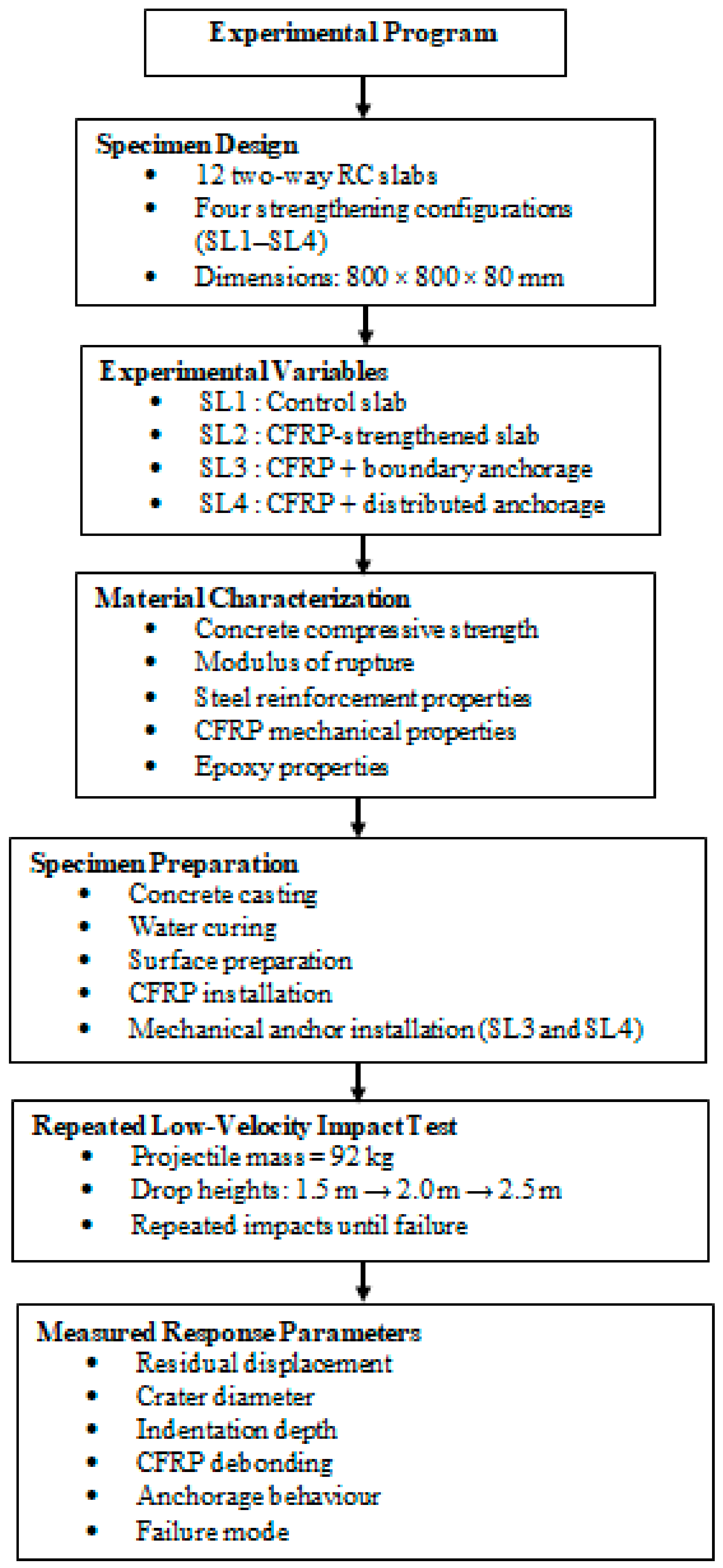
Figure 1 presents the overall experimental program adopted in this study. The flowchart summarizes the specimen configurations, investigated variables, testing procedure, and measured response parameters used to evaluate the repeated low-velocity impact behavior of CFRP-strengthened RC slabs.

2.2. Preparation of RC Slabs Samples

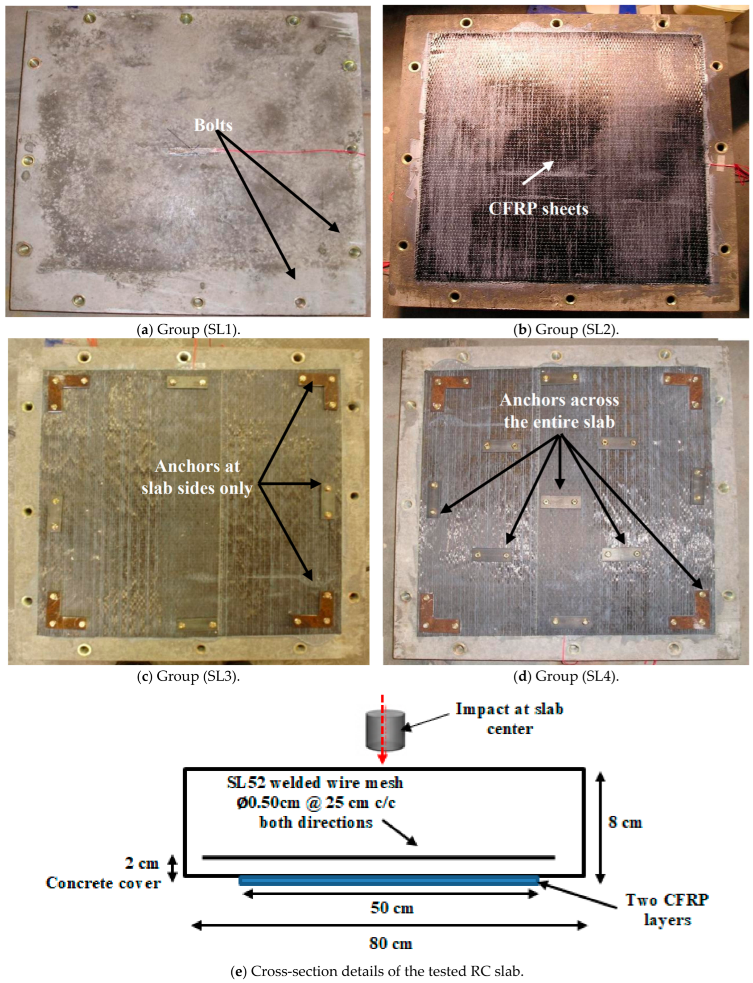
The experimental test included four groups of two-way RC slabs, consisting of three samples per group with a length and width of 80 cm and a depth of 8 cm, as presented in Table 1 and Figure 2. The RC slabs were strengthened using different CFRP sheet configurations over a 50 × 50 cm2 area at the tension face; moreover, additional anchorage was performed using steel support to avoid uplift of the RC slab during testing. A single layer of SL52 welded wire mesh, comprising 0.50 cm diameter reinforcing wires spaced at 25 cm in both orthogonal directions, was placed near the bottom tension face of the slab with a concrete cover of 2 cm.
Table 2 presents the average values of the compressive strength ( f c ) and rupture modulus ( f r ) of the concrete used in the slab specimens. The reinforcing steel consisted of SL52 wire mesh type with a yield strength of 500 MPa and a modulus of elasticity of 200 GPa. The CFRP type (Sika Wrap-230C) with a thickness of 0.13 mm was cut into square layers 50 × 50 cm2 to strengthen the RC slabs [31]. This material has a modulus of elasticity and a tensile strength of 230 GPa and 3500 MPa, respectively. The Sikadur-330 epoxy type was used to bond the CFRP sheets to the RC slab surface, which consisted of two resins mixed in a ratio of 4 to 1. This material has a modulus of elasticity of 4.5 GPa and a tensile strength of 30 MPa.

2.2.1. Installation of Strengthening Sheets

The CFRP sheets utilized in this study are unidirectional; therefore, two orthogonal layers were applied to each slab to provide bidirectional strengthening, as recommended in FRP strengthening applications for two-way RC elements [32,33]. The CFRP installation procedure consisted of three main stages to ensure adequate performance. First, the surface of the slab was mechanically roughened using an abrasive grinding tool to remove laitance and enhance surface roughness, which is important for achieving a sufficient bond in externally bonded FRP systems [34].
Second, the two-component Sikadur-330 epoxy resin was mixed based on the manufacturer’s recommended proportion and stirred for approximately three minutes until both a uniform consistency and color were achieved. Lastly, the sheets were cautiously placed on the surface covered with epoxy and pressed with a roller to achieve a complete impregnation of the fibers and be free of air voids. This process was repeated until resin was seen to bleed through the fiber tows, which means that the fiber tows are properly saturated and bonded. The second CFRP layer was applied within 60 min at 25 °C, following the same procedure and oriented normal to the first layer to achieve a bidirectional strengthening configuration. After installation, the samples were cured at an ambient temperature of 25 °C for three days before testing, in accordance with typical epoxy curing requirements for externally bonded FRP systems [35,36].

2.2.2. Installation of Anchors

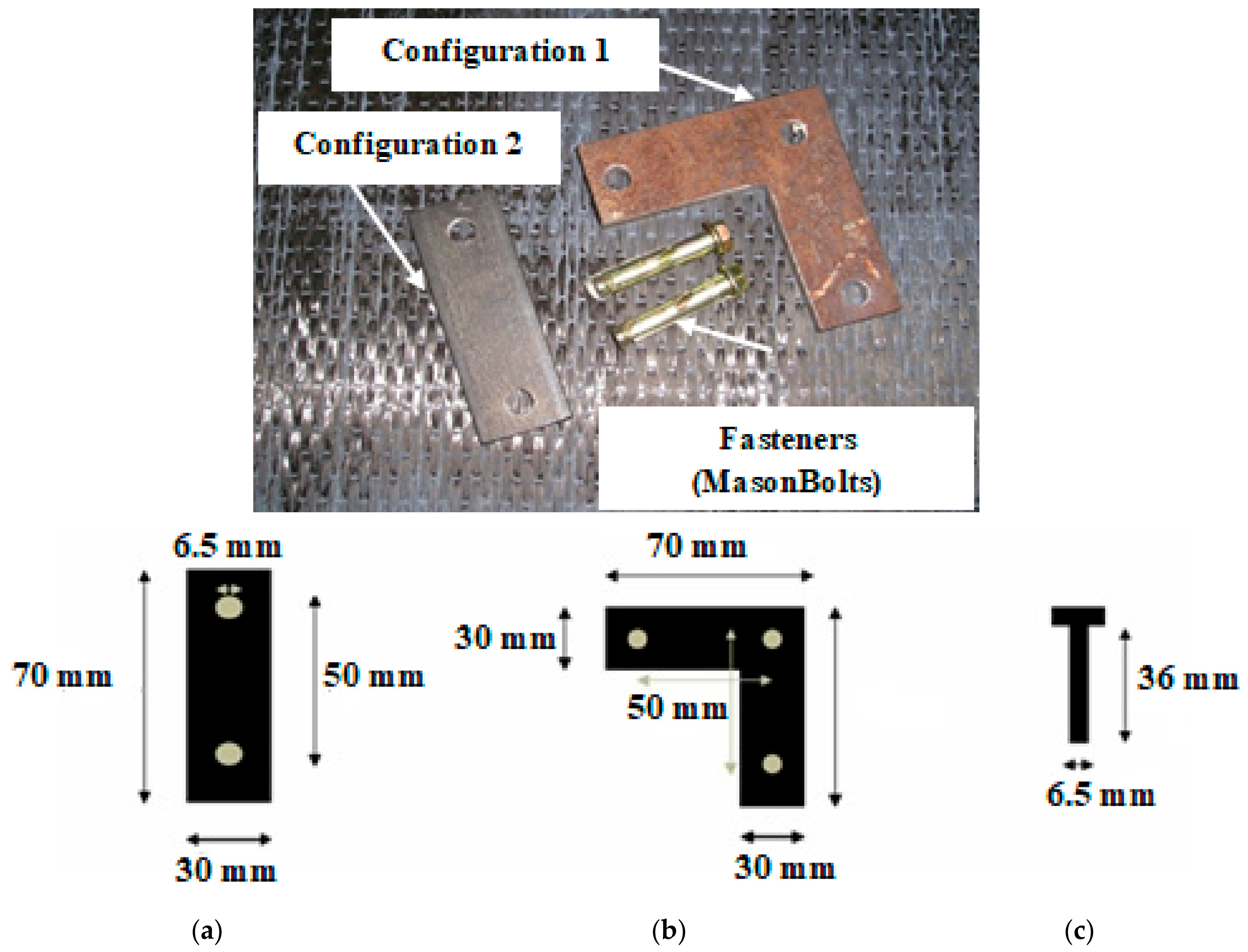
The anchors were applied exclusively to the strengthened slabs with CFRP sheets. The anchors were fastened to the RC slabs using two configurations of steel plate [37], as shown in Figure 3.
Anchor installation was carried out after full curing of the concrete samples and complete hardening of the CFRP laminate. A 6.50 mm diameter concrete drill bit, corresponding to the bolt diameter, was utilized to prepare the anchor holes. Following the manufacturer’s guidelines, the holes’ depth was determined as the minimum embedment depth plus half the anchor diameter to account for drilling debris. Considering the thinness of the slab, drilling was carefully carried out so as to ensure that there was no interference with the internal slab structure. The steel plates were positioned, and the holes were drilled to a depth of 36 mm. The Masonbolts were then driven into the holes until the bolt heads were flush with the steel plate surface. The fasteners were subsequently tightened using a spanner by a minimum of three complete nut turns, which resulted in the lower portion expanding and thus enhancing the interlocking and anchorage capacity in the concrete substrate [38,39]. The installation torque or anchor preload was not directly measured. However, all anchors were installed following the same manufacturer’s recommended installation procedure, including identical drill diameter, embedment depth, and tightening method for all specimens. Thus, any slight difference in anchor preload resulting from manual tightening is expected to have a negligible effect on the comparative evaluation of the different strengthening configurations.

2.3. Impact Test Setup

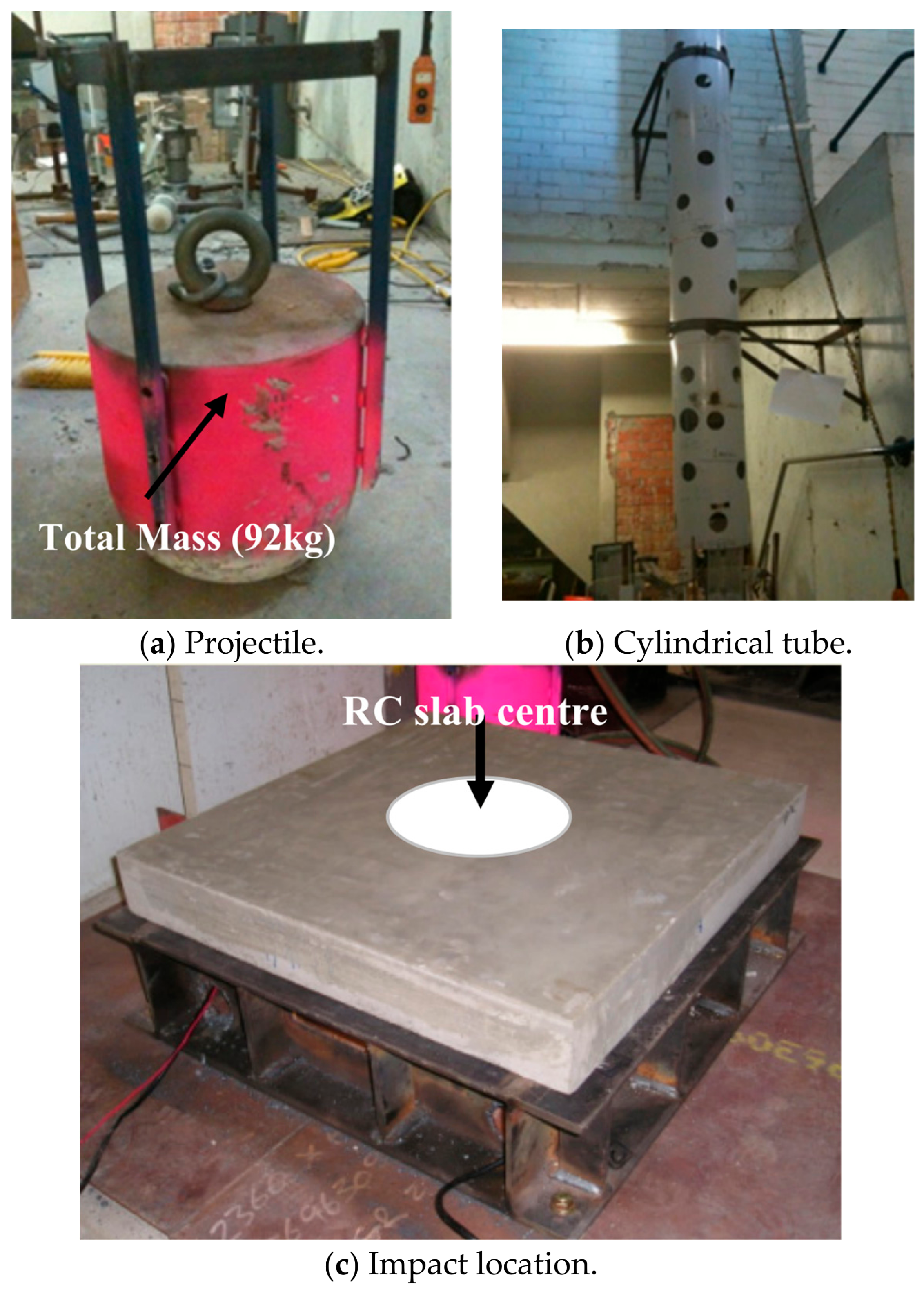
The impact test was performed using a solid steel projectile with a mass of 92 kg, as shown in Figure 4a, dropped from a predetermined height through a cylinder-guided tube shown in Figure 4b to impact the top center of the reinforced concrete slab, as shown in Figure 4c. Multiple holes were drilled along the guide tube to diminish the effect of atmospheric air resistance on the projectile’s motion. Repeated impact tests were performed on each concrete slab sample, increasing the drop height until the structure was completely damaged. Table 3 summarizes the complete repeated impact loading history, including the impact number, drop height, measured impact velocity, theoretical potential energy, calculated impact kinetic energy, and final response of each slab group. A high-speed MotionBLITZ Cube camera was utilized to record the projectile’s impact speed. This camera system recorded images with 1000 frames/s with a resolution of 640 × 512 pixels and 32,000 frames/s at reduced resolutions. The actual impact kinetic energy was calculated from the measured impact velocity using the following equation:
E k = 1 2 m v 2
where E k is the impact kinetic energy (J), m is the projectile mass (92 kg), and v is the measured impact velocity (m/s).
As presented in Table 3, the calculated kinetic energies are in close agreement with the corresponding theoretical potential energies, confirming that friction and guidance effects within the drop tube had only a minor influence on the projectile velocity. All samples were initially examined at a release height of one and a half meters, corresponding to a theoretical potential energy of approximately 1353 J. The drop height was then raised to two meters, with a theoretical potential energy of 1805 J, and failure was observed in the slab groups (SL1 and SL2) that were not provided with an anchorage system. On the other hand, the slab groups SL3 and SL4 with anchorage systems were able to withstand higher impact energy and only failed at a drop height of two and a half meters with a theoretical potential energy of approximately 2256 J. After each impact, the crater diameter, indentation depth, and residual displacement were measured manually using a steel ruler with a measurement accuracy of ±1 mm. The crater diameter was measured as the maximum diameter of the damaged area on the top surface, while the indentation depth was measured as the maximum depth at the center of the impact crater. The residual displacement after unloading was measured at the slab center.

2.4. Numerical Modeling

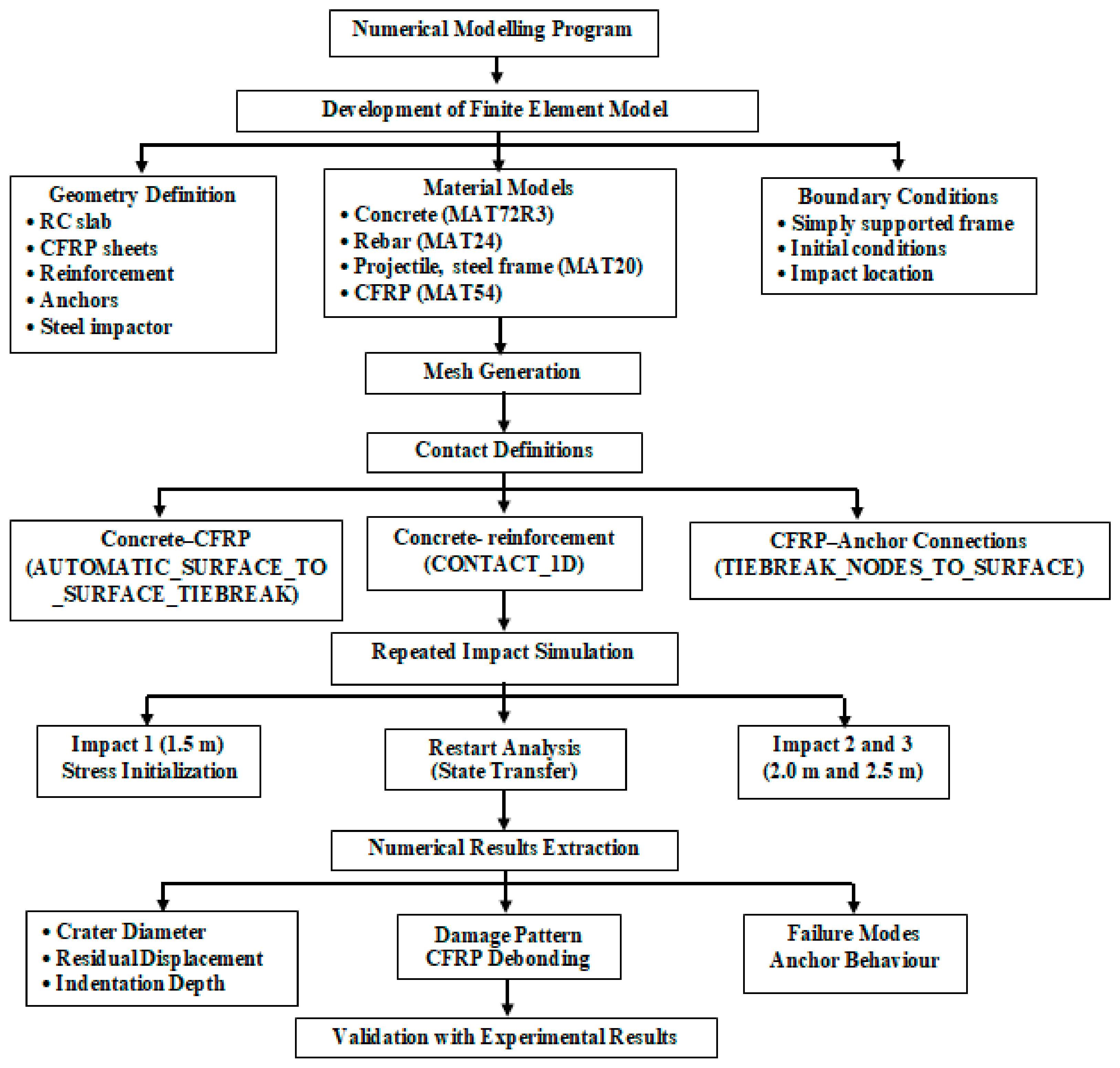
Figure 5 presents the complete flowchart of the adopted finite element modeling procedure, including geometry definition, material constitutive modeling, contact interactions, boundary conditions, repeated impact simulation, model calibration, and validation against the experimental results.

2.4.1. Details of Elements, Meshing, and Boundary Conditions

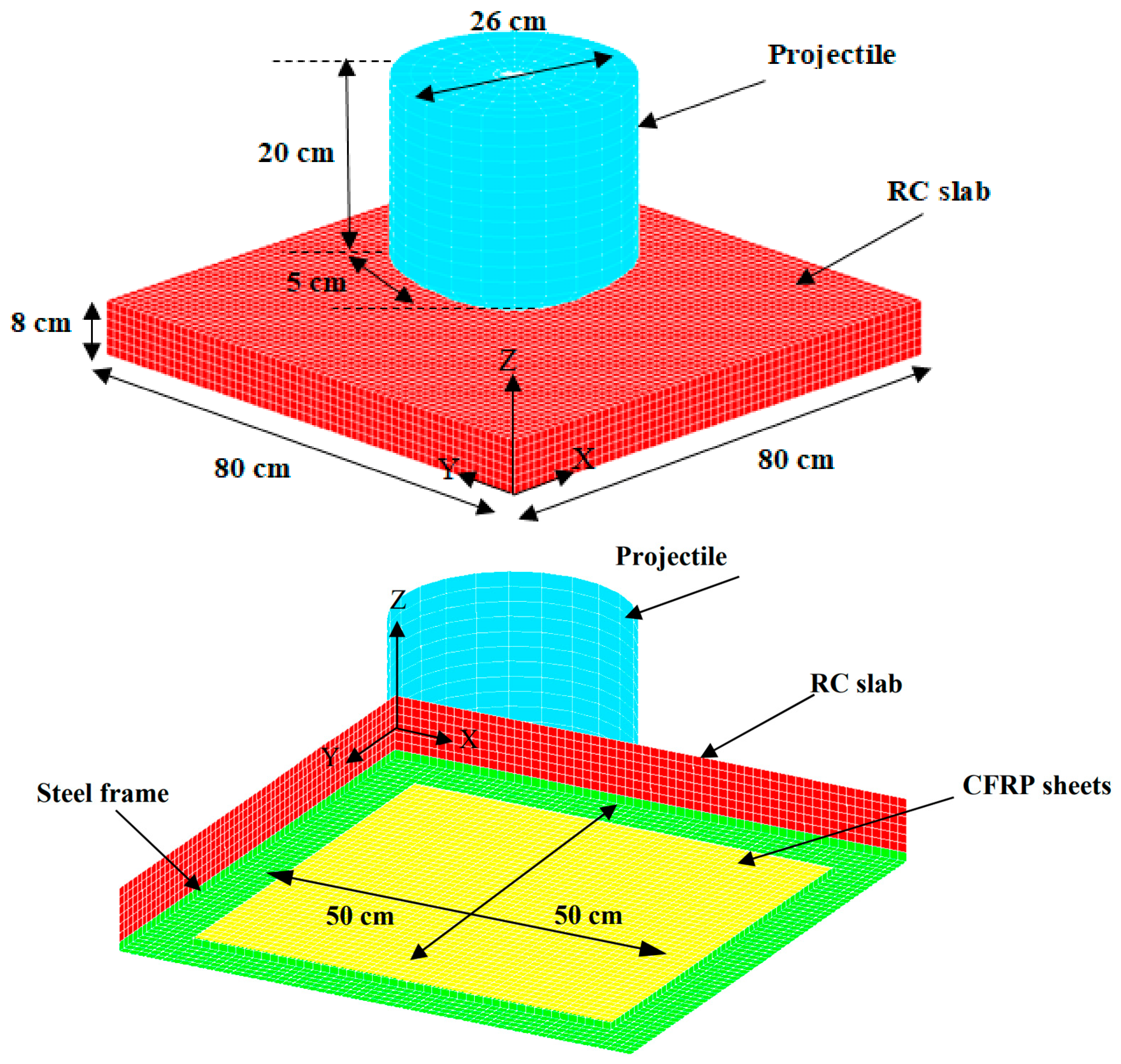
The numerical modeling of the RC slab groups was conducted using LS-DYNA software R12 [40], as presented in Figure 6.
The concrete slab and projectile were discretized using eight-node solid elements with a mesh size of 1 cm, which was found to be the most suitable element size based on a mesh sensitivity analysis conducted using mesh sizes of 1, 1.5, and 2 cm. Further mesh refinement resulted in only marginal differences in the predicted structural response while considerably increasing the computational time. Accordingly, the 1 cm mesh was selected for all subsequent numerical simulations.
The rebar was modeled by two-node Hughes–Liu elements with 2 × 2 Gauss integration, while the sheets of CFRP were simulated by Belytschko–Tsay shell elements [40] with a size of 1 cm for the entire strengthened area of 50 × 50 cm2. This type of modeling has been extensively used in the impact analysis of reinforced concrete and FRP-strengthened members, since it is well suited to capture the damage in the vicinity of impact and the response of the whole structure under impact loading [30,41,42]. The nodes of the slab corresponding to the bolt anchorage locations and the steel frame were restrained in all directions to replicate the employed boundary conditions during the impact test.

2.4.2. Material Modeling

Concrete
The MAT_CONCRETE_DAMAGE_REL3 (MAT_72R3) model is widely utilized for modeling the nonlinear response of reinforced concrete members under extreme dynamic loading [40] owing to its capability to account for the strain rate effects, damage evolution, stiffness degradation, cracking, and realistic prediction of local and global damage under impact loads, as stated by various studies [28,43,44]. The MAT_ADD_EROSION option was incorporated to account for severe concrete failure and large deformations during impact and avoid excessive mesh distortion and numerical instability due to loss of load-carrying capacity. The concrete elements were removed whenever the maximum tensile stress exceeded the values of rupture modulus shown in Table 2 or when the maximum principal strain reached 0.10. These criteria have been employed in several numerical studies of impact-loaded concrete structures, and the results showed their ability to provide reasonably accurate simulation results for concrete fragmentation, spalling, and perforation while maintaining computational stability [45,46]. The average values of concrete compressive strength and modulus of rupture reported in Table 2 were specified as the principal input parameters for the MAT_72R3 model, with an average density of 2430 kg/m3 and a Poisson’s ratio of 0.20. The remaining constitutive parameters required by MAT_72R3, including damage-related parameters and pressure-dependent variables, were generated internally by the material formulation according to the specified concrete strength parameters [40].
Steel Rebar Reinforcement
The MAT_PIECEWISE_LINEAR_PLASTICITY (MAT_24) available in LS-DYNA software R12 library [40] is widely utilized to simulate the steel rebar under dynamic loading because it can define the complete stress–strain relationship through a piecewise linear curve and account for the strain rate effects by defining the dynamic increase factor applied to the yield stress. Therefore, it can precisely capture the yielding and plastic distortion of rebar under high impact loads. The input parameters adopted for MAT_24 are shown in Table 4.
Projectile, Steel Frame, and CFRP Sheets
In this study, MAT_RIGID (MAT_20) [40] was used to model the projectile and steel frame, which were considered rigid bodies. This assumption was commonly utilized in impact numerical simulations due to the stiffness and strength of the impactor and supported frame being significantly higher than those of the target structure strength in order to reduce the computational cost without affecting the precision of the estimated slab behavior [41]. The adopted input parameters for MAT_20 are presented in Table 5.
The CFRP sheets were modeled using the MAT_ENHANCED_COMPOSITE_DAMAGE (MAT_54) owing to its ability to incorporate the Chang–Chang failure criteria and enable progressive failure simulation of orthotropic composite materials [40]. This material model can capture the failure of CFRP fibers, which are classified into four types: tensile, compressive, matrix tensile cracking, and matrix compressive crushing. Once failure criteria have been attained, the corresponding material properties are degraded according to the failure evolution law, and a precise estimation of the rupture of CFRP, the initiation of debonding, and the energy dissipation under impact loading can be performed. Prior investigations had revealed that MAT_54 offers reliable estimates of the dynamic behavior and damage levels of RC structural members strengthened with CFRP sheets under extreme loading conditions [47,48,49]. The input parameters of MAT_54 are shown in Table 6. The CFRP sheets were discretized using shell elements with orthotropic material directions assigned according to the actual fiber orientation in the experimental specimens.

2.4.3. Dynamic Increase Factor (DIF) Curves of the Concrete and Reinforcement

The effects of strain rate for concrete and steel reinforcement were accounted for using the well-established empirical (DIF) formulations stated in prior studies [50,51,52]. The Malvar and Ross formulation [50] was utilized for the tensile DIF of concrete, the CEB model was adopted for the compressive DIF of concrete [51], and the Malvar formulation was applied for the steel reinforcement [52]. On the other hand, the strain rate effects of CFRP sheets were neglected due to their limited strength enhancement, especially under medium and low impact velocities, as demonstrated by various scholars [53,54,55].

2.4.4. Contact Algorithms

Several studies have reported that assuming a perfect bond between concrete and reinforcing steel is insufficient for accurately predicting the dynamic response of reinforced concrete (RC) members subjected to impact loading [56,57,58,59]. The bond-slip behavior under high-rate loading may have a significant effect upon the degradation of stiffness, energy dissipation, and local failure mechanisms [60]. Therefore, the bond-slip effects were incorporated by using the CONTACT_1D formulation available in LS-DYNA software R12 to simulate the interaction between concrete and reinforcing bars. This model represented the bond behavior by an elastic–plastic interface law with a maximum shear stress ( τ m a x ) calculated by using the following relationship based on the concrete strength and confinement conditions [60]:
τ m a x = G s u m a x e h d m g D
where G s denotes the modulus of bond shear controlling the initial interface stiffness and set to 20 MPa/mm; u m a x represents the elastic slip capacity, which is set to 1 mm; and h d m g and D are set to 0.10, which signify the damage evolution parameter and the accumulated damage variable, respectively. The contact interfaces between the concrete slab, reinforcing steel, and steel impactor are defined using AUTOMATIC_SURFACE_TO_SURFACE to prevent numerical penetration under large deformation and impact loading [40]. This formulation offers stable contact execution for dissimilar meshes and material interfaces in dynamic numerical analysis.
To account for the adhesive bond behavior and possible debonding, the AUTOMATIC_SURFACE_TO_SURFACE_TIEBREAK contact was used to model the concrete–CFRP interface. The interface response was controlled by traction–separation laws expressed through normal and shear failure stresses (NFLS and SFLS), which represented the epoxy-layer strength. The debonding process started when the quadratic stress criterion was satisfied; that occurred when the normal and shear stresses exceeded their limited values, resulting in progressive stiffness degradation and immediate loss of interfacial cohesion, as expressed in the following equation:
( | σ n | N F L S ) 2 + ( | σ s | S F L S ) 2 1
where σ n and σ s denote the tensile and shear stresses at the interface, respectively. The bond strength of epoxy material typically ranged from 4 to 30 MPa according to the manufacturer’s company properties, and this strength was mainly dependent on the surface preparation, period, and environmental conditions of curing. A numerical analysis of RC slab group SL2 was first conducted to calibrate the interface parameters because the CFRP dependency was not observed in the first impact, while it occurred during the second impact. The results showed that the N F L S and S F L S values must be equal to 10 MPa to provide the best agreement with experimentally observed debonding response. Accordingly, this value was adopted for all RC slab groups strengthened with CFRP sheets. The anchors were simulated via the (TIEBREAK_NODES_TO_SURFACE) contact formulation proposed by a prior study [61] to signify the interface among the anchors and both CFRP sheets and the concrete substrate at the fastener positions. This formulation required initial compatibility between the master and slave surfaces, which is emulated until a predefined failure criterion has been satisfied. When the stresses at the interface exceeded the limits, progressive debonding and separation were triggered based on the defined traction-based failure envelope as follows:
( | σ n | N F L S ) N E N + ( | σ s | S F L S ) M E S 1
where σ n and σ s signify the normal and shear stresses obtained during the analysis at the interface, and N E N and M E S denote the exponents for the normal and shear stress components, which are both set to 2. The values of N F L S and S F L S represent the normal and shear stress values, which are equal to 1.50 MPa and 1.70 MPa, respectively. The adopted NFLS and SFLS values were derived from the manufacturer’s safe working capacities and converted into equivalent interface stresses considering the effective contact area of the anchor in the numerical model. The interface properties utilized in this study are illustrated in Table 7.

2.4.5. Impact Load Simulation

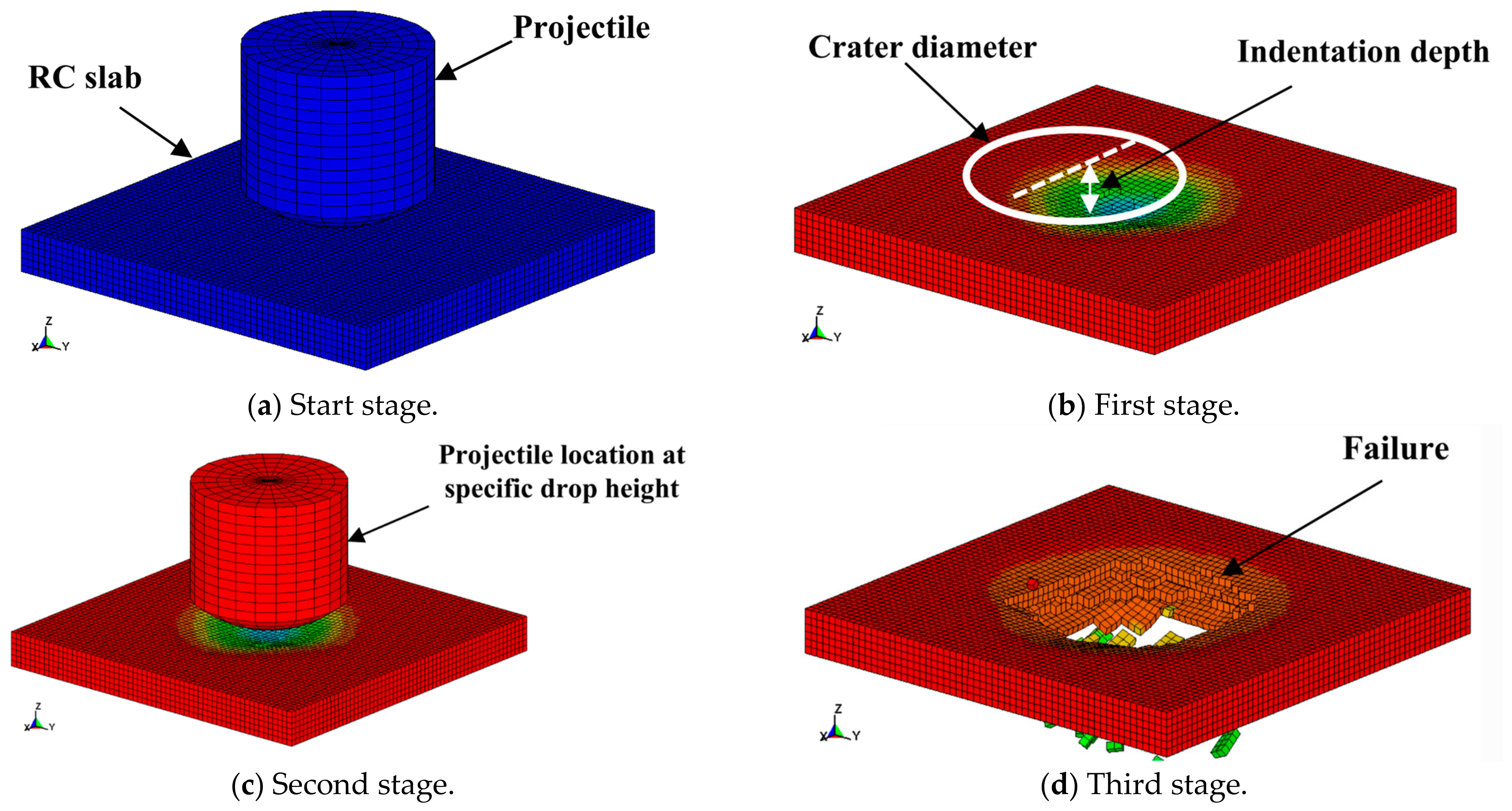
The repeated impact load was simulated by using the restart analysis capability available in the LS-DYNA software [40]. The technique employed a full-deck restart possibility, whereas the response state from the earlier analysis was utilized as the initial state for the next analysis. In the initial route, the impact load and the entire structure state involved the nodal displacements, strains, stresses, and internal forces, which were stored as a binary d3dump file. This state was then mapped into the preceding run via the utilized *STRESS_INITIALIZATION* keyword, which permitted the damaged and pre-stressed condition of the complete structure to be preserved between consecutive impacts. The LS-DYNA software offers a full restart option, which was utilized due to its significant modification capability in the model, such as the removal and reintroduction of the impactor between impact events.
During each impact stage, a full restart was conducted to remove the rigid impactor and start the post-impact equilibrium state. A subsequent full restart was then performed to reintroduce the impactor with the measured velocity during the experimental impact test, in that manner simulating the next impact while retaining all accumulated damage from the earlier impacts. This process was repeated according to the number of impact events applied during the experimental program. The SL1 and SL2 slab groups were subjected to two consecutive impacts at drop heights of 1.50 m and 2 m, respectively, while the SL3 and SL4 slab groups underwent three consecutive impacts at drop heights of 1.50 m, 2 m, and 2.50 m. The accumulated damage state after each impact was preserved through the restart analysis procedure. The restart analysis sequence and corresponding damage evolution are shown in Figure 7 for the case of the unstrengthened RC slab group (SL1).
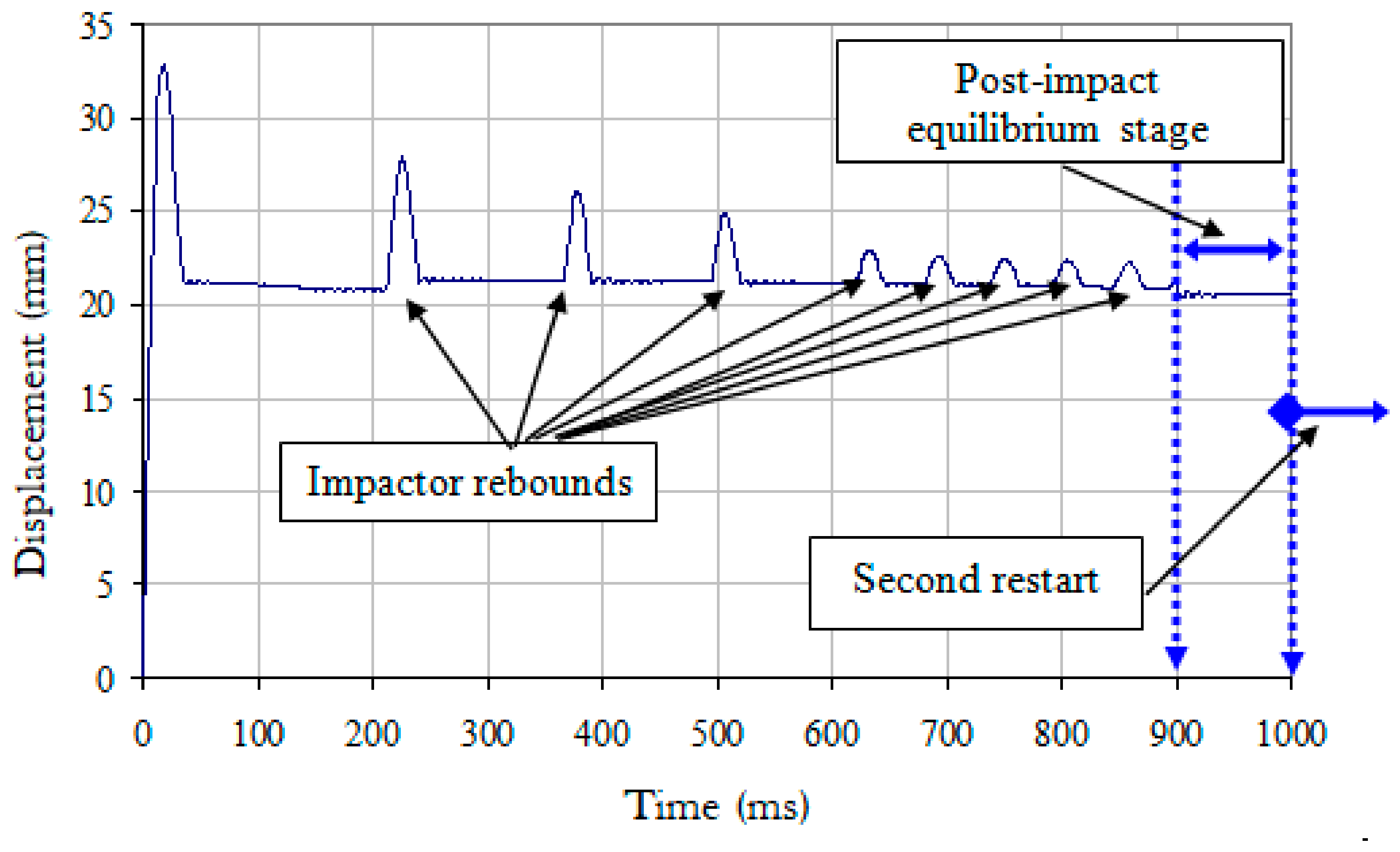
The impact event was first modeled until the rigid steel impactor reached a near-stationary state, after which a restart analysis was carried out to begin the post-impact condition before applying the subsequent impact. Furthermore, the numerical model reproduced the general rebound behavior of the rigid impactor observed during the experimental impact tests, as shown in Figure 8. However, a quantitative comparison of the rebound response was not possible, because the experimental rebound history was not recorded. The analysis was terminated when the impact velocity decreased below 0.1 m/s to ensure that the impact response had fully dissipated.

3. Results and Discussion

The experimental behavior of the RC slab groups under repeated low-velocity impact loading is presented in this section and compared with the corresponding numerical simulations. Since three specimens were tested for each slab configuration, all reported experimental damage parameters represent the average values obtained from the tested specimens.

3.1. Experimental and Numerical Validation Results at a 1.50 M Drop Height

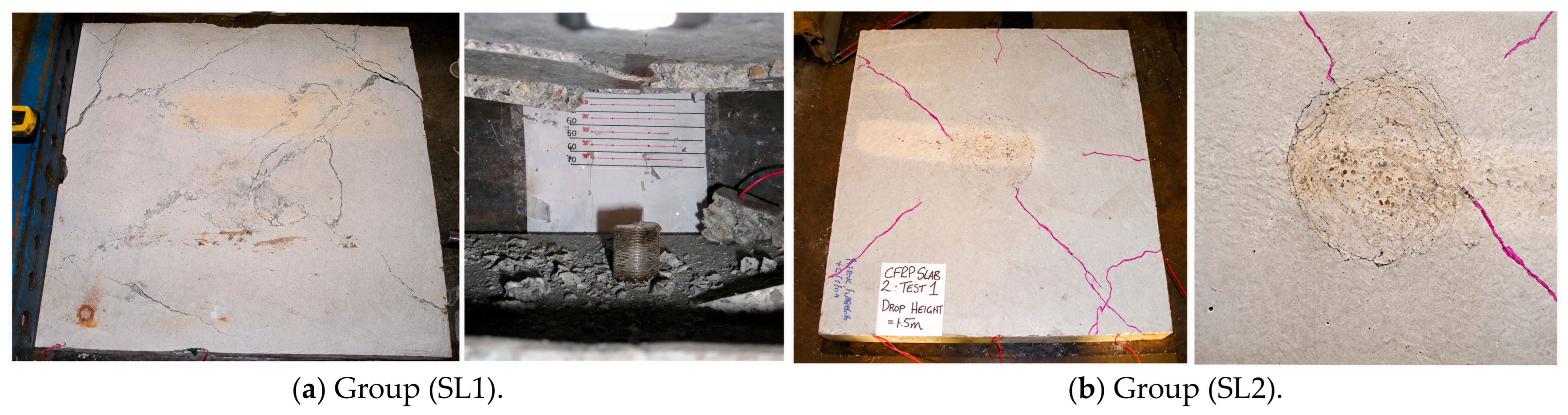
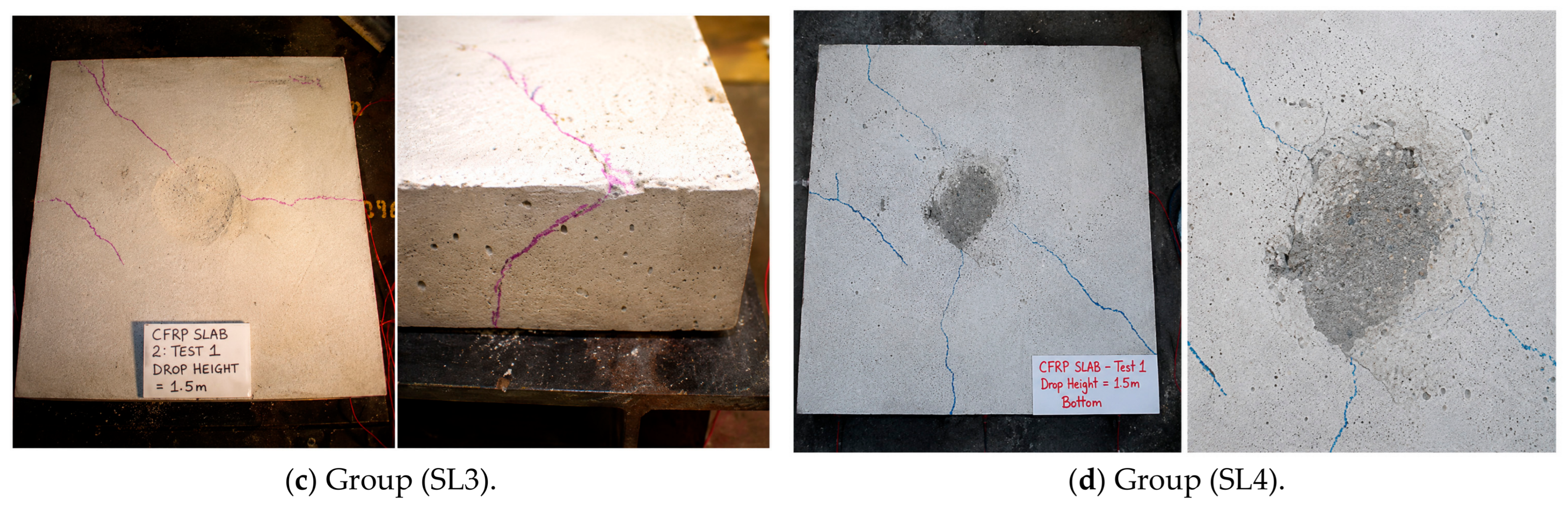
The control RC slab group (SL1) exhibited the most severe damage, with extensive flexural cracking, considerable spalling of the bottom face, and a large impact crater with an average crater diameter and indentation depth of 40 cm and 2 cm, respectively, as shown in Figure 9a. The average recorded residual displacement was 3 cm, and extensive flexural deformation developed throughout the slab, in addition to local crushing damage. The impact resistance of the slab group (SL2) strengthened with CFRP sheets was considerably improved, as shown in Figure 9b. The damage was mainly concentrated in the impact area, whereas the average crater diameter, indentation depth, and residual displacement were reduced to 18 cm, 0.60 cm, and 1 cm, respectively. The results revealed that the strengthening with CFRP sheets successfully limited crack propagation and effectively prevented severe spalling and shifted the damage from global to mainly local damage.
In the slab group (SL3), the crater diameter and indentation depth were further decreased and recorded average values of 16 cm and 0.30 cm, respectively, with an average residual displacement of 0.70 cm, as shown in Figure 9c. This improvement might be attributed to the presence of the mechanical anchors, which significantly enhanced the bond integrity between the CFRP sheets and concrete substrate and delayed the premature CFRP debonding. In the slab group (SL4), the average values of crater diameter, indentation depth, and residual displacement were 15 cm, 0.40 cm, and 0.90 cm, respectively, as presented in Figure 9d. The local damage remained localized with no CFRP debonding observed, and the internal anchors provided only marginal benefits compared to the anchors utilized in the RC slab group (SL3). In general, the findings confirm that the CFRP strengthening significantly enhanced the dynamic impact response of RC slabs by decreasing the deformation of the exposed region. The incorporation of mechanical anchors further improved the RC slab performance due to the ability to maintain the CFRP–concrete bond under impact loading, while the additional internal anchors provided only limited benefits under the investigated impact energy level.
The observed improvement in impact resistance due to externally bonded CFRP agrees with previous studies [62,63], which reported that CFRP reinforcement effectively limits crack propagation and reduces impact-induced deformation through enhanced tensile resistance and energy absorption. However, unlike these earlier investigations, which primarily considered single impact events, the present study demonstrates that the beneficial effect of CFRP can be maintained under repeated impacts when mechanical anchorage is employed to preserve the CFRP–concrete bond.
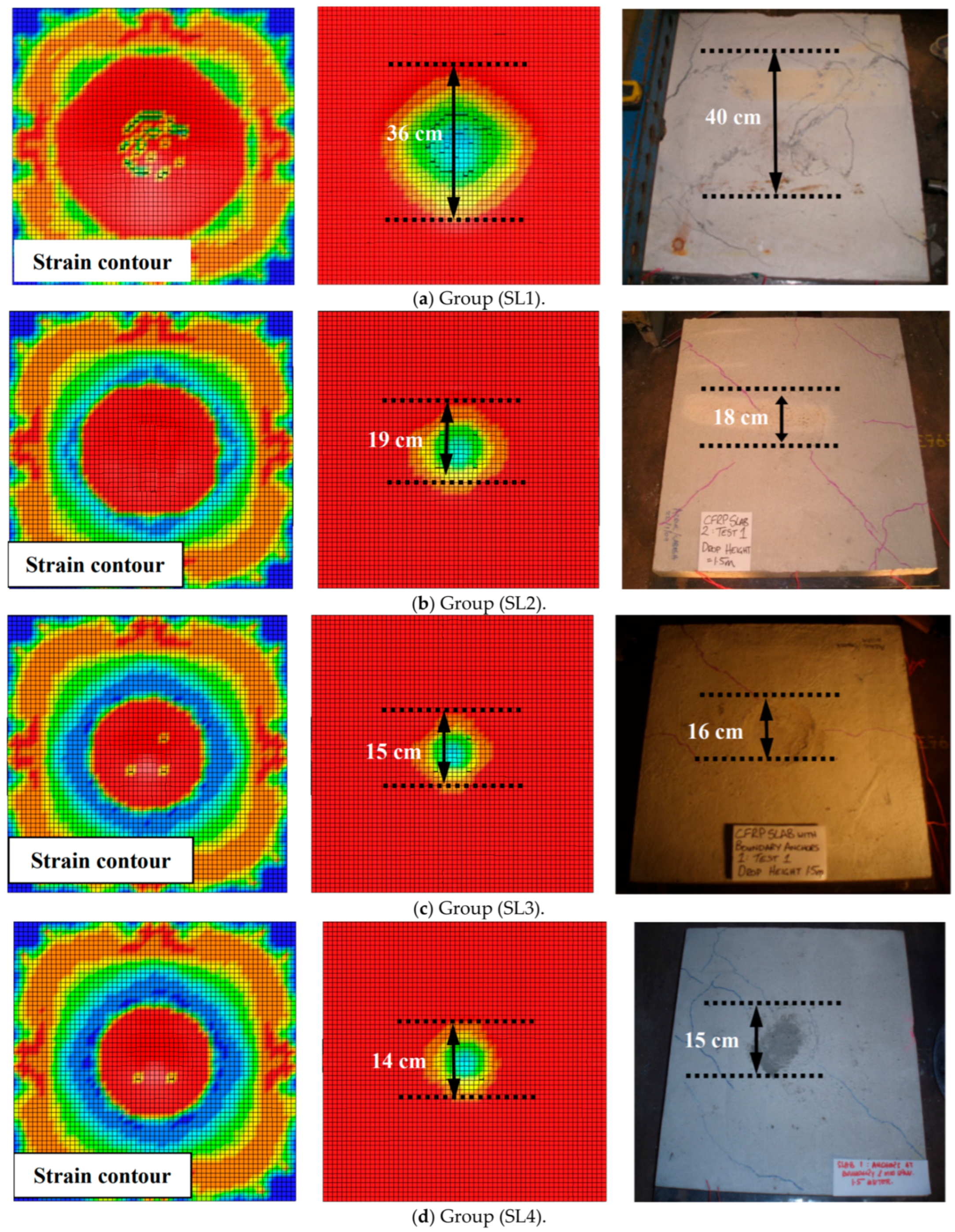
The numerical analysis was performed to simulate the failure modes of RC slab groups under a drop height of 1.50 m as shown in Figure 10. Since the concrete–CFRP interface parameters (NFLS and SFLS) were calibrated using the experimentally observed debonding behaviour of slab group SL2, the comparison for this group represents the calibration process. The remaining slab groups (SL1, SL3, and SL4) were subsequently used as independent validation cases for the proposed numerical model. For the RC slab (SL1) group, the results revealed good consistency, and the slabs exhibited severe local damage with predicted average values for the crater diameter, indentation depth and residual displacement of 36 cm, 2.03 cm, and 2.73 cm with deviations of −10%, 1.50%, and −9%, respectively, as compared with the experimental observations as shown in Figure 10a. For the calibrated SL2 specimen, the numerical model accurately reproduced the experimentally observed local damage and global deformation under repeated impact loading, as shown in Figure 10b. The predicted crater diameter, indentation depth and residual displacement were 19 cm, 0.63 cm, and 1.05 cm, respectively, with deviations of 5.56%, 5%, and 5% as compared with the experimental results.
Localized impact damage was captured for the RC slab group (SL3) strengthened with CFRP sheets and anchorage systems on the slab boundaries, as shown in Figure 10c. The outcomes closely matched the experimental results in terms of crater diameter, indentation depth, and residual displacement within differences of −6.30%, 3%, and 12.80%, respectively. Furthermore, the numerical model of the slab group (SL4) indicated localized impact damage at the 1.5 m drop height, as illustrated in Figure 10d. The predicted values of crater diameter and indentation depth were 14 cm and 0.34 cm, with differences reaching up to −6.67% and −15%, respectively, as compared with experimental results. However, the predicted residual displacement was 0.81 cm, slightly lower than the mean experimental value of 0.90 cm, corresponding to differences of approximately −10%. Overall, the above results demonstrated that the calibrated numerical model successfully reproduced the observed response of the SL2 specimen and accurately predicted the behavior of the independent validation specimens (SL1, SL3, and SL4). In addition, the mechanical anchorage further enhanced structural performance by maintaining the CFRP–concrete bond and delaying debonding.

3.2. Experimental and Numerical Validation Results at a 2 M Drop Height

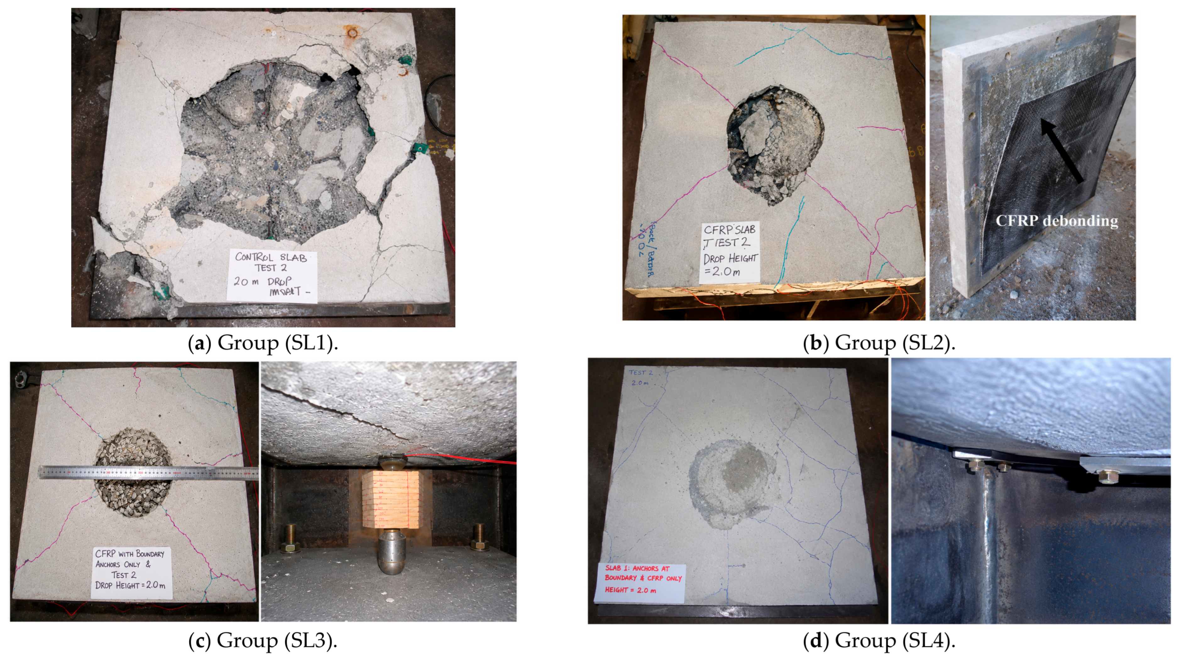
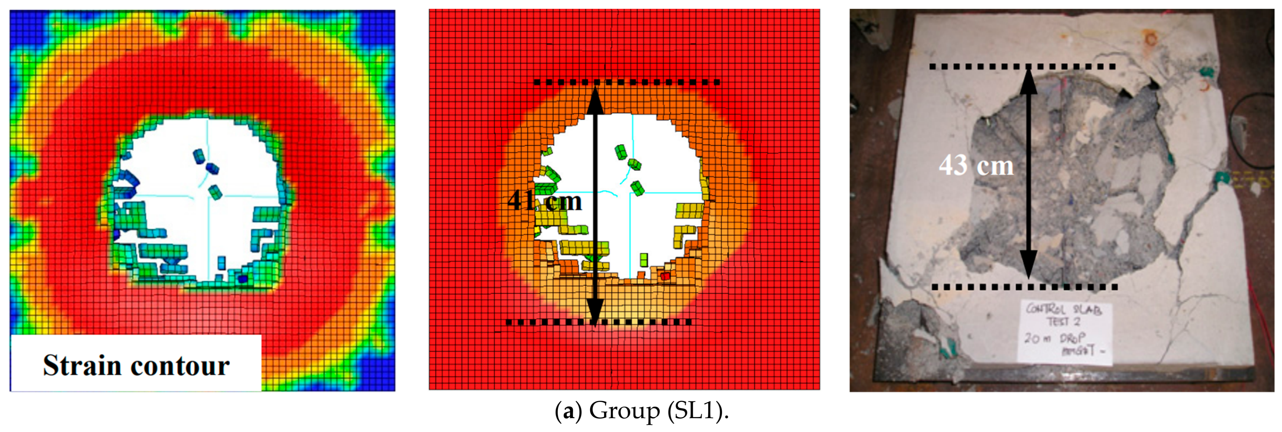
The interface parameters calibrated from the SL2 specimen were retained without modification for all subsequent simulations. The RC slab group (SL1) was then tested under a 2 m drop height, with an average impact speed of 6090 mm/s. The observed failure mode of the slab was catastrophic, complete perforation with an average crater diameter of approximately 43 cm, as shown in Figure 11a. Wide diagonal shear cracks were observed close to the supports, and flexural cracks propagated near the slab boundary. The governing failure mode was a combination of punching, perforation, and global flexural-shear response, indicating complete loss of structural integrity.
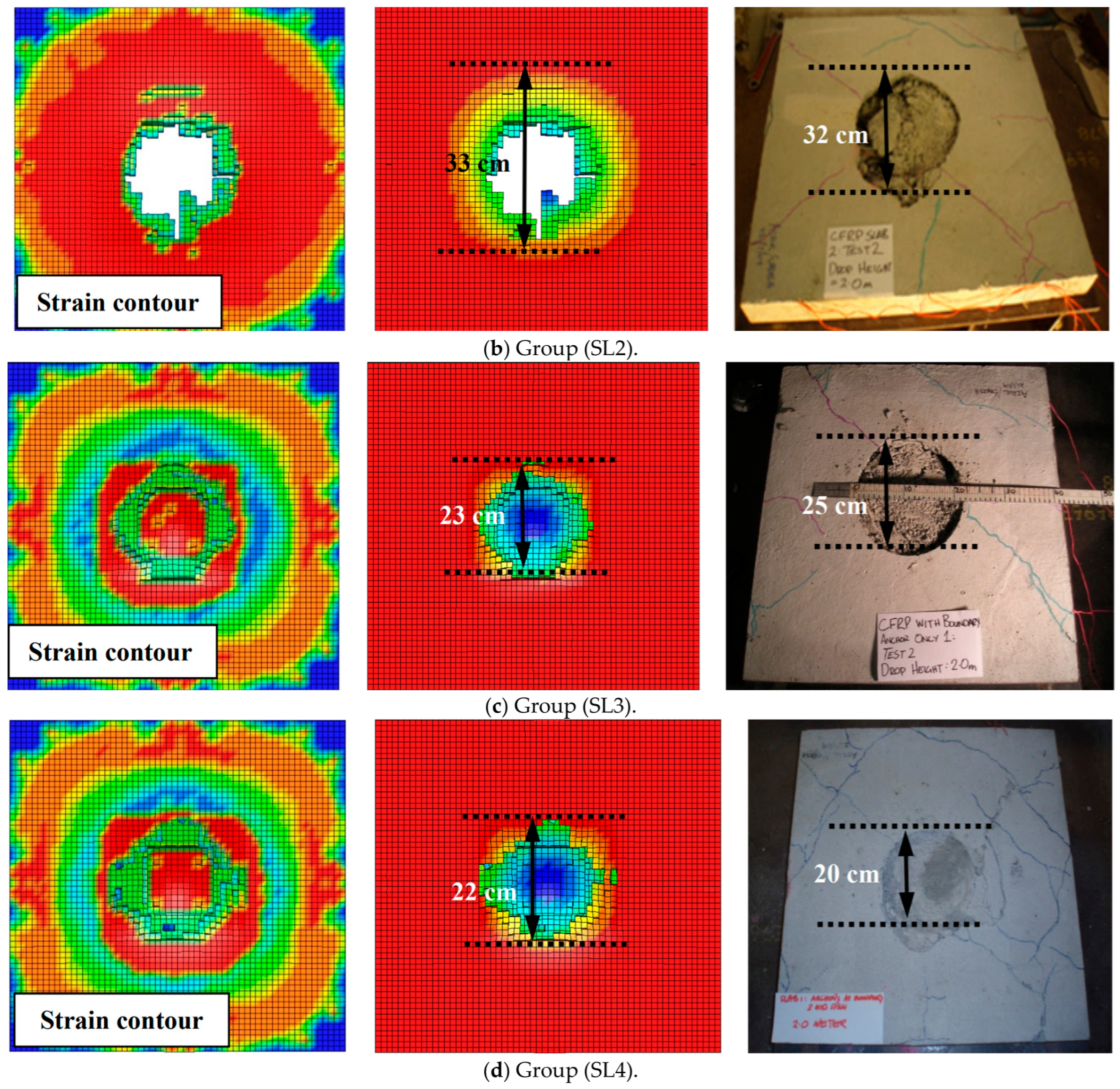
At a similar drop height with an average impact speed of approximately 6200 mm/s, a perforation failure in the RC slab group (SL2) was also observed with a smaller crater diameter of 32 cm as compared with the RC slab group (SL1). The CFRP strengthening prevented the propagation of flexural cracks; however, extensive CFRP sheet debonding and minor ruptures were observed, as shown in Figure 11b. The premature damage of the bond diminished the effectiveness of the strengthening system, which revealed that bond failure controlled the behavior of the RC slab with CFRP strengthening under repeated dynamic impact loading.
On the other hand, the group (SL3) was able to withstand the impact of a 2 m drop height with an average impact speed of 6100 mm/s without perforation, as illustrated in Figure 11c. The crushing zone recorded average values of 25 cm, 2.50 cm, and 3 cm for the crater diameter, indentation depth, and residual displacement, respectively. Small cracks of shear and flexure were noted without debonding of CFRP sheets, and all the anchors were effective. The slab failure was governed by localized punching shear, indicating a significant improvement in energy absorption and structural resilience. Likewise, the RC slab group (SL4) showed a superior performance under a 2 m release height with an average impact speed of 6150 mm/s, where the damaged area remained localized, with average values of crater diameter, indentation depth, and residual displacement of 20 cm, 2.4 cm, and 2.50 cm, respectively, as observed in Figure 11d. The results showed no rupture or debonding in CFRP sheets, and all the anchors remained intact. The damage was governed by scabbing with limited penetration, which highlights the role of anchorage schemes and CFRP strengthening to prevent catastrophic failure. Generally, the outcomes indicated that externally bonded CFRP reduced damage severity; however, its effectiveness was limited by debonding. The combination of mechanical anchorage prevented bond failure, improved stress transfer, and considerably boosted the resistance of the strengthened slabs exposed to repeated high-energy impacts.
The premature CFRP debonding for unanchored slabs was observed in previous studies [27,63,64], where interface failure was identified as the governing damage mechanism under dynamic loading. The present results further demonstrate that mechanical anchorage effectively delays this failure mechanism, allowing the strengthened slabs to sustain higher impact energies before perforation. This finding provides additional experimental evidence regarding the effectiveness of anchorage systems under repeated impact loading, which has received limited attention in previous investigations.
At a 2 m drop height, the numerical model of the RC slab group (SL1) closely matched the experimental results, and the slabs were fully perforated, with an average perforation diameter of 41 cm, with deviations of only −4.70%, as shown in Figure 12a. Similarly, the numerical simulation of the RC slab group (SL2) also predicted complete perforation, with an average diameter of 33 cm, with differences of only 3.13% compared with the experimental results, as shown in Figure 12b.
The numerical model of RC slab group (SL3) showed a similar failure pattern as captured during the impact test at a drop height of 2 m, and the slabs were capable of resisting the applied impact load with average values of crater diameter, indentation depth, and residual displacement of 23 cm, 2.37 cm, and 2.62 cm, and differences reached up to −8%, −5.20%, and −12.67%, respectively, as compared with the experimental test, as described in Figure 12c. Likewise, the RC slab group (SL4) showed behavior similar to that observed in the experimental tests, and the slabs exhibited localized damage without perforation and recorded average values of the crater diameter, indentation depth, and residual displacement of 22 cm, 2.50 cm, and 2.70 cm, with differences of 10%, 4.17%, and 8%, as compared with the experimental test, as shown in Figure 12d.
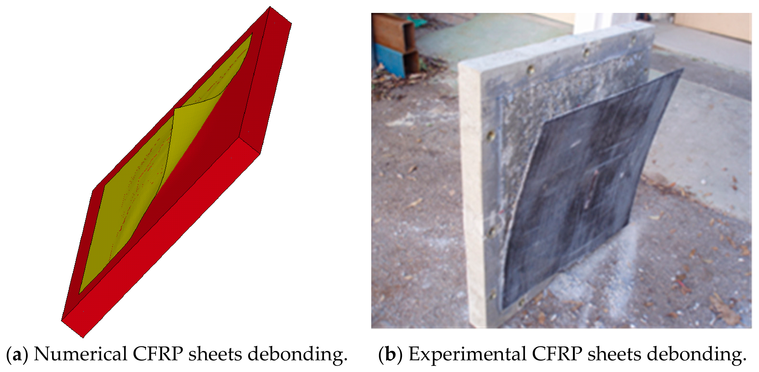
Furthermore, the model successfully captured the CFRP debonding failure that was observed during the experimental test, as shown in Figure 13. However, some differences were observed in the predicted CFRP failure mechanism. During the experimental impact test, the CFRP fracture was mainly concentrated near the slab center, while debonding covered a large area of the CFRP sheet. Conversely, multiple CFRP fractures were observed during the numerical analysis with a limited debonded area. These differences might be attributed to several factors that affect the bond strength and fracture behavior of epoxy adhesives, such as surface preparation, curing conditions, adhesive thickness, and strain-rate effects, which lead to a difficult characterization. However, the dominant failure mechanisms were well described, and the numerical model was capable of capturing the structural behavior of RC slab strengthened with CFRP sheets.
Overall, the results proved that the beneficial effect of externally bonded CFRP under repeated impacts is strongly dependent on maintaining an effective bond with the concrete substrate. While the unanchored CFRP-strengthened slabs experienced premature debonding and perforation, the mechanically anchored slabs successfully resisted the higher impact level without catastrophic failure. The finite element model accurately captured the progressive damage evolution, perforation behavior, and CFRP debonding, confirming its capability to simulate and predict the structural behavior of these building members under repeated impact loads.

3.3. Experimental and Numerical Validation Results at a 2.50 M Drop Height

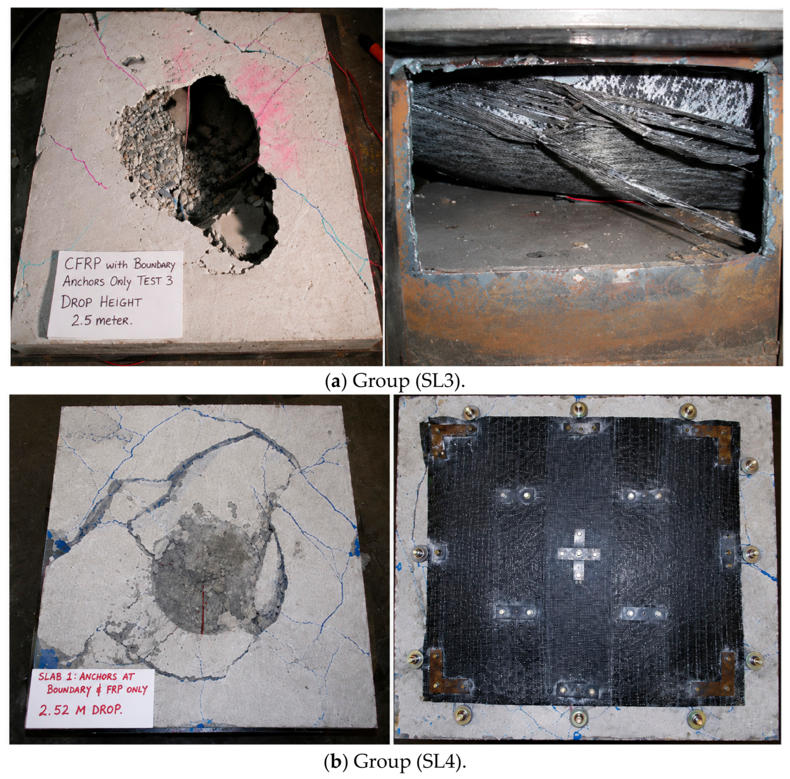
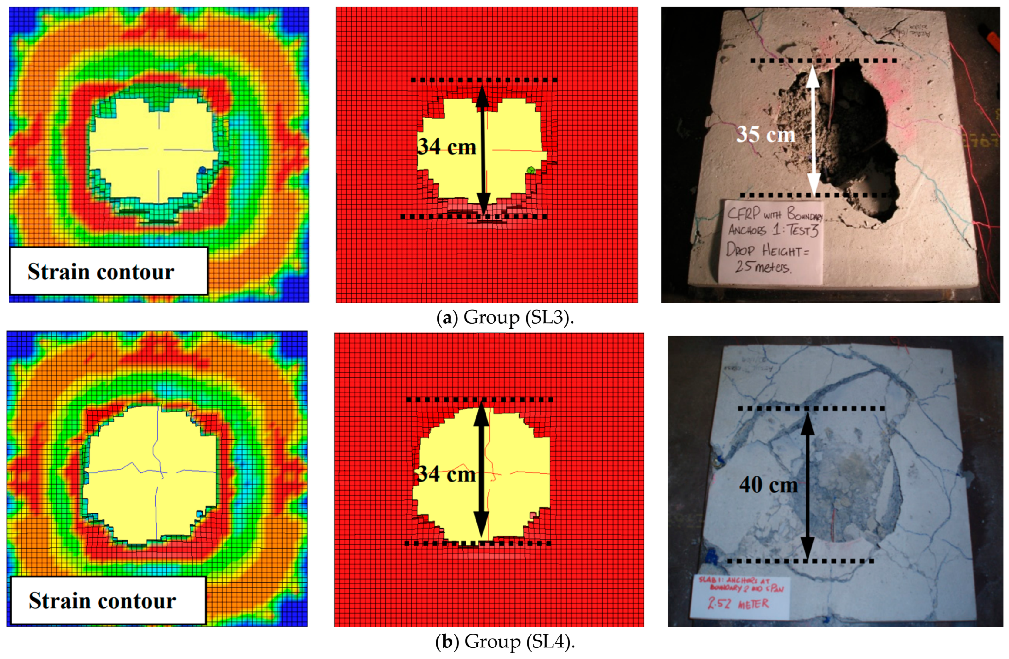
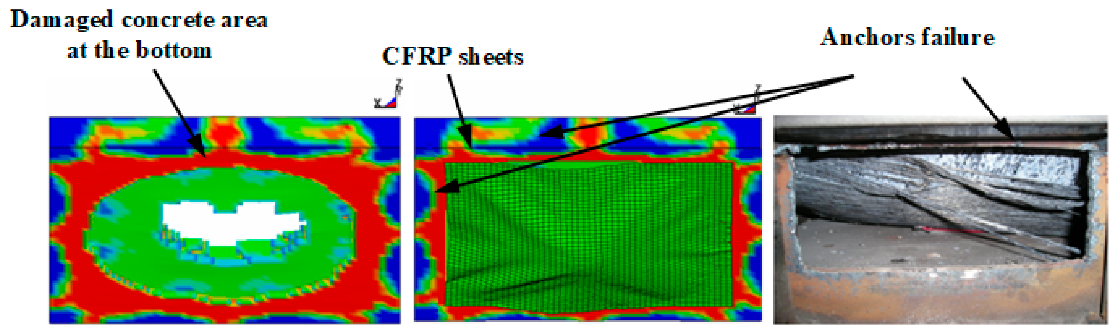
The RC slabs of groups SL3 and SL4 exhibited local damage without full perforation at a drop height of 2 m. Consequently, the slabs were further tested under a 2.50 m drop height, with an average released speed of 6900 mm/s. The RC slabs of the SL3 group were fully perforated with an average diameter of 35 cm, as captured in Figure 14a. Flexural cracks were noted and propagated towards the slab boundaries, with diagonal shear cracks formed close to the support zones. The CFRP sheets were extensively ruptured and debonded from the concrete surface. Two corner anchors were pulled out, while the other anchors remained in place. The results indicated that even though the anchorage system delayed debonding, the strengthened system reached its resistance limit under the subjected impact energy. This behavior was observed by different scholars on several structural members, such as slab, column, and beam [21,49,65].
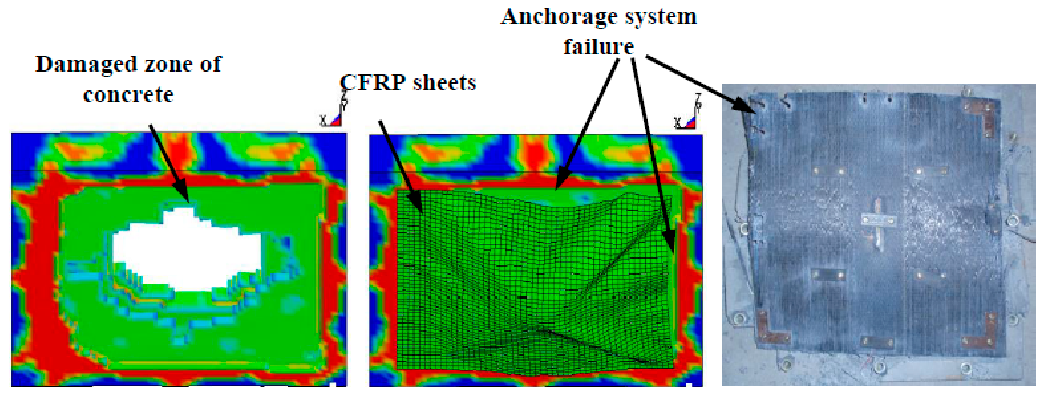
The slabs in group SL4 were subsequently tested at a 2.5 m drop height with an average impact speed of 7020 mm/s, as shown in Figure 14b. Severe localized punching shear failure developed beneath the impact point with an average perforation diameter of 40 cm. Compared with the SL3 specimens, more extensive flexural and diagonal shear cracking was observed, and three boundary anchors were pulled out during the impact. Moreover, the localized concrete damage was more pronounced; however, the CFRP sheets remained partially attached to the concrete surface. These observations suggested that the additional internal anchors did not significantly reduce the local concrete damage at the highest impact level but helped maintain partial attachment of the CFRP sheets despite local anchor failures, thereby delaying complete debonding. Similar observations were reported by previous studies [49,66], which demonstrated that mechanical anchorage improves stress transfer and delays CFRP debonding under severe loading conditions. Overall, the results demonstrated that the use of additional internal anchors provided a limited improvement over the boundary anchorage with the increase in impact energy. Furthermore, the excessive number of anchors pulled out could impose minor threats for the surrounded structures and people.
The numerical analysis of the RC slab group (SL3) revealed a full slab perforation at a 2.50 m drop height, which closely matched the failure mode observed during the experimental test with an average crater diameter of 34 cm and a deviation of −2.86%, as shown in Figure 15a.
Moreover, several anchor connections were pulled out, consistent with the experimental observations shown in Figure 16. The above outcomes demonstrated the capability of the adopted modeling to capture the concrete damage, CFRP rupture, and the behavior of the anchorage system under repeated impact loading, providing reliable predictions for anchored CFRP-strengthened RC slabs.
For the RC slab group (SL4), the numerical model efficiently reproduced the perforation behavior observed during the experimental test at a 2.50 m drop height. The predicted crater diameter was 34 cm, corresponding to a deviation of −15% compared with the measured value. This difference could be attributed to the idealized material constitutive models and contact assumptions, which tend to produce more localized damage zones. Nevertheless, the estimated failure pattern and mechanism remain in close agreement with the experimental investigations, as shown in Figure 15b.
In addition, the numerical model successfully captured the damage of the anchorage system of the RC slab group (SL4), as illustrated in Figure 17. The predicted failure locations were consistent with the experimental observations, demonstrating that the adopted anchor failure criterion effectively captured the progressive debonding and failure of the anchorage system under repeated impact loading. These results further confirm that the interfaces between the CFRP sheets, anchors, and concrete substrate were appropriately represented in the developed numerical model.
Overall, the numerical results showed good agreement with the experimental observations for the different slab configurations and impact levels investigated. The proposed finite element model was capable of reproducing the main response characteristics, including damage progression, CFRP debonding, anchorage failure, and cumulative damage development, during successive impacts using the restart analysis approach. The obtained results demonstrate the capability of the developed modeling strategy to simulate the behavior of CFRP-strengthened RC slabs subjected to repeated low-velocity impact loading. A comparison between the experimental and numerical results, including the corresponding deviations, is summarized in Table 8.

4. Conclusions

The outcomes of this study can be summarized as follows:
  • Externally bonded CFRP sheets considerably enhanced the impact resistance of RC slabs by decreasing residual displacement and local damage, while shifting the failure mode from global flexural damage to localized punching damage as compared with the unstrengthened slab group (SL1).
  • Premature CFRP sheets’ debonding governed the failure of the slab group (SL2) strengthened without mechanical anchorage at a 2 m drop height, restricting the efficiency of the strengthening scheme.
  • Mechanical anchorage successfully delayed CFRP sheets’ debonding, improved load transfer, and avoided catastrophic perforation of the slab group (SL3) at a 2.0 m drop height. The boundary anchorage system provided most of the strengthening advantage, whereas the additional internal anchors utilized in the slab group (SL4) revealed only limited enhancement under moderate impact velocities, but enhanced structural integrity under high velocities, accomplished at an impact height of 2.5 m.
  • The established finite element models precisely reproduced the experimental failure evolution, perforation response, CFRP sheets’ debonding, anchor damage, and residual displacement in all the investigated cases.
From an engineering perspective, the results demonstrate that combining externally bonded CFRP sheets with mechanical anchorage provides an effective strengthening solution for reinforced concrete slabs subjected to repeated low-velocity impacts. The proposed strengthening approach improves structural resilience by maintaining the CFRP–concrete bond and delaying catastrophic failure under repeated impact loading. In addition, the validated numerical model provides a reliable tool for evaluating strengthening schemes and supporting the design of impact-resistant RC structures while reducing the need for extensive experimental testing. Future work should investigate the influence of different anchorage layouts, CFRP strengthening configurations, reinforcement ratios, slab thicknesses, and higher-impact energy levels. Further experimental and numerical investigations considering different boundary conditions, impact masses, and repeated impact scenarios are recommended to further expand the applicability of the proposed strengthening system.

Author Contributions

Conceptualization, A.A.M. and H.H.; methodology, M.H.M. and A.A.M.; software, M.H.M. and A.A.M.; validation, M.H.M. and A.A.M.; formal analysis, M.H.M., A.A.M., and H.H.; investigation, M.H.M. and A.A.M.; resources, A.A.M. and H.H.; data curation, M.H.M. and H.H.; writing—original draft, M.H.M. and A.A.M.; writing—review and editing, M.H.M.; visualization, A.A.M. and H.H.; supervision, A.A.M. and H.H.; project administration, A.A.M. and H.H.; funding acquisition, A.A.M. and H.H. All authors have read and agreed to the published version of the manuscript.

Funding

The authors would like to thank the Malaysian Ministry of Higher Education and National University of Malaysia for providing financial support through Fundamental Research Grant Scheme (FRGS/1/2024/SSI12/UKM/02/3).

Data Availability Statement

The data presented in this study are available upon request from the corresponding author.

Conflicts of Interest

The authors declare that they have no conflicts of interest.

References

  1. Chiquito, M.; López, L.M.; Castedo, R.; Santos, A.P.; Pérez-Caldentey, A. Full-scale field tests on concrete slabs subjected to close-in blast loads. Buildings 2023, 13, 2068. [Google Scholar]
  2. Shirai, T.; Kambayashi, A.; Ohno, T.; Taniguchi, H.; Ueda, M.; Ishikawa, N. Experiment and numerical simulation of double-layered RC plates under impact loadings. Nucl. Eng. Des. 1997, 176, 195–205. [Google Scholar] [CrossRef]
  3. Laczák, L.E.; Károlyi, G. Local effects of impact into concrete structure. Period. Polytech. Civ. Eng. 2016, 60, 573–582. [Google Scholar] [CrossRef]
  4. Lu, Y. Impact on reinforced concrete structures. In Encyclopedia of Continuum Mechanics; Springer: Berlin/Heidelberg, Germany, 2020; pp. 1309–1332. [Google Scholar]
  5. Cadoni, E.; Caldentey, A.P.; Colombo, M.; Dancygier, A.N.; di Prisco, M.; Grisaro, H.; Martinelli, P.; Ožbolt, J.; Pająk, M.; Weerheijm, J. State-of-the-art on impact and explosion behaviour of concrete structures: Report of RILEM TC 288-IEC. Mater. Struct. 2025, 58, 62. [Google Scholar] [CrossRef]
  6. Sangi, A.; May, I. High-mass, low-velocity impacts on reinforced concrete slabs. In Proceedings of the 7th European LS-DYNA Conference, Salzburg, Austria, 14–15 May 2009. [Google Scholar]
  7. Zineddin, M.; Krauthammer, T. Dynamic response and behavior of reinforced concrete slabs under impact loading. Int. J. Impact Eng. 2007, 34, 1517–1534. [Google Scholar] [CrossRef]
  8. Tahmasebinia, F.; Remennikov, A. Simulation of the reinforced concrete slabs under impact loading. In Proceedings of the Australasian Structural Engineering Conference 2008: Engaging with Structural Engineering, Melboume, VIC, Australia, 26–27 June 2008. [Google Scholar]
  9. Saatci, S. Behaviour and Modelling of Reinforced Concrete Structures Subjected to Impact Loads. Ph.D. Thesis, University of Toronto, Toronto, ON, Canada, 2007. [Google Scholar]
  10. Yao, S.; Zhang, D.; Chen, X.; Lu, F.; Wang, W. Experimental and numerical study on the dynamic response of RC slabs under blast loading. Eng. Fail. Anal. 2016, 66, 120–129. [Google Scholar] [CrossRef]
  11. Zhong, J.; Song, C.; Zhang, Z.; Zhang, H.; Liu, F. Experimental and theoretical investigations on reinforced concrete slabs subjected to low-velocity impact at various points by a drop hammer. Thin-Walled Struct. 2025, 213, 113326. [Google Scholar] [CrossRef]
  12. Li, C.; Zhi, X.; Song, M.; Lan, C.; Li, S.; Fan, F. Behavior of unbonded prestressed concrete slabs subjected to low-velocity impact loading. Eng. Struct. 2024, 308, 118006. [Google Scholar] [CrossRef]
  13. Al-Dala’ien, R.N.; Syamsir, A.; Kodrg, A.-F.J.; Usman, F.; Abdullah, M.J. The effect of continuous rectangular spiral shear reinforcement on the dynamic behavior of RC solid slab subjected to low-velocity impact loading. Results Eng. 2024, 21, 101942. [Google Scholar] [CrossRef]
  14. Abolhassani, A.; Peyman, S.; Eskandari, A.; Shamami, S.Z. Experimental and Numerical Study on Reinforced Concrete Slab Subjected to Open and Closed-End Drop Weight Impact. Results Eng. 2025, 27, 106364. [Google Scholar] [CrossRef]
  15. Abu Altemen, A.A.G.; Medhlom, M.K.; Özakça, M. Structural behavior of Full-Scale novel hybrid layered concrete slabs reinforced with CFRP and steel grids under impact load. Buildings 2024, 14, 2625. [Google Scholar] [CrossRef]
  16. Ojaimi, M.F.; Alabdulhady, M.Y.; Naser, K.Z. Influence of Concrete Compressive Strength on CFRP Strengthening and Repairing of RC Two-Way Slabs. J. Eng. 2024, 2024, 2166919. [Google Scholar] [CrossRef]
  17. Mohsen, S.; Makhlouf, M.H.; Badawi, M.I.; Ismail, G. Evaluating the Splice Effect on the Flexural Performance of RC Beams Reinforced with Hybrid and GFRP Rebars. Int. J. Concr. Struct. Mater. 2026, 20, 36. [Google Scholar] [CrossRef]
  18. Masoudiyan, M.; Kargaran, A. Strengthening of Two-Way Slabs Using Fiber Reinforced Concrete, Near Surface Mounted and CFRP Layers under Impact Loading. arXiv 2025. [Google Scholar] [CrossRef]
  19. Zhang, Y.; Duan, L.; Liu, H.; Lu, J.; Huo, Y. Experimental and numerical study on multi-impact performance of pre-damaged beams strengthened with CFRP. Eng. Struct. 2023, 285, 116034. [Google Scholar] [CrossRef]
  20. Zhou, Y.; Ye, Z.; Zhao, D.; Huang, Z.; Yang, L. Static and multi-impact performances of RC beams strengthened with large rupture-strain FRP composites. Compos. Struct. 2023, 316, 117053. [Google Scholar] [CrossRef]
  21. Swesi, A.O.; Cotsovos, D.M.; Val, D.V. Effect of CFRP strengthening on response of RC columns to lateral static and impact loads. Compos. Struct. 2022, 287, 115356. [Google Scholar] [CrossRef]
  22. Eslami, A.; Shayegh, H.R.; Moghavem, A.; Ronagh, H.R. Experimental and analytical investigations of a novel end anchorage for CFRP flexural retrofits. Compos. Part B Eng. 2019, 176, 107309. [Google Scholar] [CrossRef]
  23. Mofidi, A.; Chaallal, O.; Benmokrane, B.; Neale, K. Performance of end-anchorage systems for RC beams strengthened in shear with epoxy-bonded FRP. J. Compos. Constr. 2012, 16, 322–331. [Google Scholar] [CrossRef]
  24. Al-Tamimi, A.K.; Hawileh, R.; Abdalla, J.; Rasheed, H.A. Effects of ratio of CFRP plate length to shear span and end anchorage on flexural behavior of SCC RC beams. J. Compos. Constr. 2011, 15, 908–919. [Google Scholar] [CrossRef]
  25. Al-Bukhaiti, K.; Yanhui, L.; Shichun, Z.; Daguang, H. Investigating the effectiveness of CFRP strengthening in improving the impact performance of RC members. Structures 2024, 60, 105841. [Google Scholar] [CrossRef]
  26. Çalışkan, Ö.; Aras, M.; Yılmaz, T.; Anıl, Ö. Experimental and numerical investigation of low-velocity impact behavior and failure mode of shear deficient RC beam strengthened with CFRP strips. Struct. Concr. 2025, 26, 856–878. [Google Scholar]
  27. Erbaş, Y.; Ghoroubı, R.; Mercimek, Ö.; Anıl, Ö.; Karaalp, A. Experimental and numerical investigation of impact behaviour of anchored CFRP-to-concrete bonding interface. Theor. Appl. Fract. Mech. 2024, 133, 104603. [Google Scholar] [CrossRef]
  28. Senthil, K.; Kubba, Z.; Sharma, R.; Thakur, A. Experimental and numerical investigation on reinforced concrete slab under low velocity impact loading. IOP Conf. Ser. Mater. Sci. Eng. 2021, 1090, 0120901. [Google Scholar] [CrossRef]
  29. Mizushima, Y.; Iino, N. Behavior of thin reinforced concrete slabs and effect of reinforcement bars subjected low-velocity impact. Structures 2022, 38, 832–847. [Google Scholar] [CrossRef]
  30. Yılmaz, T.; Kıraç, N.; Anil, Ö.; Erdem, R.T.; Sezer, C. Low-velocity impact behaviour of two way RC slab strengthening with CFRP strips. Constr. Build. Mater. 2018, 186, 1046–1063. [Google Scholar] [CrossRef]
  31. Sika-Australia-Pty-Ltd. Structural Strengthening. Available online: https://aus.sika.com/en/construction/structural-strengthening.html (accessed on 12 July 2026).
  32. Soudki, K.; Alkhrdaji, T. Guide for the design and construction of externally bonded FRP systems for strengthening concrete structures (ACI 440.2 R-02). In Proceedings of the Structures Congress 2005: Metropolis and Beyond, New York, NY, USA, 20–23 April 2005. [Google Scholar]
  33. Teng, J.G.; Chen, J.F.; Smith, S.T.; Lam, L. FRP: Strengthened RC Structures; Wiley: Hoboken, NJ, USA, 2002. [Google Scholar]
  34. Zheng, X.H.; Huang, P.Y.; Guo, X.Y.; Huang, J.L. Experimental Study on Bond Behavior of FRP-Concrete Interface in Hygrothermal Environment. Int. J. Polym. Sci. 2016, 2016, 5832130. [Google Scholar] [CrossRef]
  35. Sakar, G.; Hawileh, R.; Naser, M.; Abdalla, J.; Tanarslan, M. Nonlinear behavior of shear deficient RC beams strengthened with near surface mounted glass fiber reinforcement under cyclic loading. Mater. Des. 2014, 61, 16–25. [Google Scholar] [CrossRef]
  36. Assad, M.; Hawileh, R.A.; Abdalla, J.A.; Safieh, H.; Shaw, S.K. Behaviour of strengthened RC beams with CFRP and GSM sheets under cyclic loading. Compos. Part C Open Access 2025, 17, 100617. [Google Scholar] [CrossRef]
  37. Macsim-Fastenings-Pt-Ltd. Product Specification Manual. Available online: http://www.macsim.com.au/Products/Anchoring/documents/masonbolts_tech_000.pdf (accessed on 12 July 2026).
  38. Smith, S.; Teng, J. FRP-strengthened RC beams. I: Review of debonding strength models. Eng. Struct. 2002, 24, 385–395. [Google Scholar] [CrossRef]
  39. Siddiqui, N.A. Experimental investigation of RC beams strengthened with externally bonded FRP composites. Lat. Am. J. Solids Struct. 2009, 6, 343–362. [Google Scholar]
  40. LS-DYNA. Keyword User’s Manual V971; LSTC: Livermore, CA, USA, 2006. [Google Scholar]
  41. Pham, T.M.; Hao, H. Review of concrete structures strengthened with FRP against impact loading. Structures 2016, 7, 59–70. [Google Scholar] [CrossRef]
  42. Batarlar, B.; Saatci, S. Numerical investigation on the behavior of reinforced concrete slabs strengthened with carbon fiber textile reinforcement under impact loads. Structures 2022, 41, 1164–1177. [Google Scholar] [CrossRef]
  43. Vacev, T.; Zorić, A.; Grdić, D.; Ristić, N.; Grdić, Z.; Milić, M. Experimental and numerical analysis of impact strength of concrete slabs. Period. Polytech. Civ. Eng. 2023, 67, 325–335. [Google Scholar]
  44. Anas, S.; Alam, M.; Tahzeeb, R. Impact response prediction of square RC slab of normal strength concrete strengthened with (1) laminates of (i) mild-steel and (ii) C-FRP, and (2) strips of C-FRP under falling-weight load. Mater. Today Proc. 2022, 87, 9–19. [Google Scholar]
  45. Shi, Y.; Hao, H.; Li, Z.-X. Numerical derivation of pressure–impulse diagrams for prediction of RC column damage to blast loads. Int. J. Impact Eng. 2008, 35, 1213–1227. [Google Scholar] [CrossRef]
  46. Trivedi, N.; Singh, R. Prediction of impact induced failure modes in reinforced concrete slabs through nonlinear transient dynamic finite element simulation. Ann. Nucl. Energy 2013, 56, 109–121. [Google Scholar] [CrossRef]
  47. Elsanadedy, H.M.; Almusallam, T.H.; Alsayed, S.H.; Al-Salloum, Y.A. Experimental and FE study on RC one-way slabs upgraded with FRP composites. KSCE J. Civ. Eng. 2015, 19, 1024–1040. [Google Scholar] [CrossRef]
  48. Emara, M.; Hamoda, A.; Hu, J.W. Numerical assessment of rectangular one-and two-way RC slabs strengthened with CFRP under impact loads. Comput. Concr. 2023, 31, 173. [Google Scholar]
  49. Almusallam, T.; Al-Salloum, Y.; Alsayed, S.; Iqbal, R.; Abbas, H. Effect of CFRP strengthening on the response of RC slabs to hard projectile impact. Nucl. Eng. Des. 2015, 286, 211–226. [Google Scholar] [CrossRef]
  50. Malvar, L.J.; Ross, C.A. Review of strain rate effects for concrete in tension. Mater. J. 1998, 95, 735–739. [Google Scholar] [CrossRef]
  51. Béton, C.E.-I.d. CEB-FIP Model Code 1990: Design Code; Thomas Telford: London, UK, 1993. [Google Scholar]
  52. Malvar, L.J.; Crawford, J.E. Dynamic increase factors for steel reinforcing bars. In Proceedings of the 28th Department of Defense Explosives Safety Seminar (DDESB), Orlando, FL, USA, 18–20 August 1998; pp. 1–18. [Google Scholar]
  53. Koerber, H.; Xavier, J.; Camanho, P. High strain rate characterisation of unidirectional carbon-epoxy IM7-8552 in transverse compression and in-plane shear using digital image correlation. Mech. Mater. 2010, 42, 1004–1019. [Google Scholar] [CrossRef]
  54. Al-Zubaidy, H.; Zhao, X.-L.; Al-Mahaidi, R. Mechanical characterisation of the dynamic tensile properties of CFRP sheet and adhesive at medium strain rates. Compos. Struct. 2013, 96, 153–164. [Google Scholar] [CrossRef]
  55. Li, X.; Yan, Y.; Guo, L.; Xu, C. Effect of strain rate on the mechanical properties of carbon/epoxy composites under quasi-static and dynamic loadings. Polym. Test. 2016, 52, 254–264. [Google Scholar] [CrossRef]
  56. Shen, D.; Li, C.; Feng, Z.; Wen, C.; Ojha, B. Influence of strain rate on bond behavior of concrete members reinforced with basalt fiber-reinforced polymer rebars. Constr. Build. Mater. 2019, 228, 116755. [Google Scholar] [CrossRef]
  57. Monti, G.; Spacone, E. Reinforced concrete fiber beam element with bond-slip. J. Struct. Eng. 2000, 126, 654–661. [Google Scholar] [CrossRef]
  58. Liu, Y.; Hao, H.; Hao, Y. Prediction of blast response of RC columns considering dynamic bond-slip between reinforcement and concrete. Eng. Struct. 2023, 283, 115921. [Google Scholar] [CrossRef]
  59. Wei, J.; Li, J.; Wu, C.; Hao, H.; Liu, J. Experimental and numerical study on the impact resistance of ultra-high performance concrete strengthened RC beams. Eng. Struct. 2023, 277, 115474. [Google Scholar] [CrossRef]
  60. Shi, Y.; Li, Z.-X.; Hao, H. Bond slip modelling and its effect on numerical analysis of blast-induced responses of RC columns. Struct. Eng. Mech. 2009, 32, 251–267. [Google Scholar] [CrossRef]
  61. Tabiei, A.; Wu, J. Roadmap for crashworthiness finite element simulation of roadside safety structures. Finite Elem. Anal. Des. 2000, 34, 145–157. [Google Scholar] [CrossRef]
  62. Batarlar, B.; Hering, M.; Bracklow, F.; Kühn, T.; Beckmann, B.; Curbach, M. Experimental investigation on reinforced concrete slabs strengthened with carbon textiles under repeated impact loads. Struct. Concr. 2020, 22, 120–131. [Google Scholar] [CrossRef]
  63. Chen, W.; Pham, T.M.; Elchalakani, M.; Li, H.; Hao, H.; Chen, L. Experimental and numerical study of basalt FRP strip strengthened RC slabs under impact loads. Int. J. Struct. Stab. Dyn. 2020, 20, 2040001. [Google Scholar] [CrossRef]
  64. Li, G.; Tan, K.H.; Fung, T.C. Experimental study on CFRP-concrete dynamic debonding behaviour. Eng. Struct. 2020, 206, 110055. [Google Scholar] [CrossRef]
  65. Abadel, A.; Abbas, H.; Almusallam, T.; Al-Salloum, Y.; Siddiqui, N. Local impact damage response of CFRP strengthened concrete slabs. Procedia Eng. 2017, 173, 85–92. [Google Scholar] [CrossRef]
  66. Chen, J.-F.; Xie, J.H.; Tao, Y.; Li, X.-Q. A review of FRP strengthened concrete structures under extreme loading. In Proceedings of the International Conference on Performance-Based and Life-Cycle Structural Engineering, Brisbane, QLD, Australia, 9–11 December 2015. [Google Scholar]
Figure 1. Flowchart of the experimental program adopted in this study.
Buildings 16 02951 g001
Figure 2. Configurations of the tested RC slab groups and cross-sectional details of the slab.
Buildings 16 02951 g002
Figure 3. Configurations and dimensions of anchors and fasteners, (a) configuration 1, (b) configuration 2, (c) MasonBolts.
Buildings 16 02951 g003
Figure 4. Impact test equipment.
Buildings 16 02951 g004
Figure 5. Flowchart of the numerical modeling procedure adopted in this study.
Buildings 16 02951 g005
Figure 6. Numerical modeling details.
Buildings 16 02951 g006
Figure 7. Analysis of repeated impact loading and recorded damage during restart analysis stages.
Buildings 16 02951 g007
Figure 8. Numerical displacement–time history of the RC slab group (SL1) showing the rebound behavior of the impactor and the restart analysis procedure.
Buildings 16 02951 g008
Figure 9. Failure modes of slab groups at a 1.50 m drop height.
Buildings 16 02951 g009aBuildings 16 02951 g009b
Figure 10. Comparison between experimental and numerical results of RC slab groups at a 1.50 m drop height.
Buildings 16 02951 g010
Figure 11. Failure modes of slab groups at a 2 m drop height.
Buildings 16 02951 g011
Figure 12. Comparison between experimental and numerical results of RC slab groups at a 2 m drop height.
Buildings 16 02951 g012aBuildings 16 02951 g012b
Figure 13. Comparison of numerical and experimental CFRP sheets debonding failure.
Buildings 16 02951 g013
Figure 14. Failure modes of slab groups at a 2.50 m drop height.
Buildings 16 02951 g014
Figure 15. Comparison between experimental and numerical results of RC slab groups at a 2.50 m drop height.
Buildings 16 02951 g015
Figure 16. Anchorage system failure of the RC slab group (SL3) at a 2.50 m drop height.
Buildings 16 02951 g016
Figure 17. Anchorage system failure of the RC slab group (SL4) at a 2.50 m drop height.
Buildings 16 02951 g017
Table 1. Details of the tested RC slab groups.
Slab GroupDetails
SL1Slab samples without CFRP fabric
SL2Slab samples strengthened with two layers of CFRP sheets of size 50 × 50 cm bonded at the tension face
SL3Slab with CFRP sheets similar to the SL2 configuration and additional anchors applied at slab boundaries only
SL4Slab with CFRP sheets similar to the SL2 configuration and distributed anchors across the entire slab surface
Table 2. Properties of concrete batch used in RC slab groups.
Slab GroupAverage ( f r ) (MPa) Average ( f c ) (MPa)
SL1 and SL25.3934.38
SL35.9035.34
SL45.2534.31
Table 3. Summary of repeated impact loading history and final response of RC slab groups.
Slab GroupImpact No.Drop Height (m)Average Measured Impact Velocity (mm/s)Potential Energy (J)Kinetic Energy (J)Final Response
SL111.50531013531298Severe local damage
22609018051706Failure (perforation)
SL211.50531013531298Localized impact damage
22620018051769Failure (perforation with CFRP debonding)
SL311.5531013531298Localized impact damage
22610018051711Severe local damage without perforation
32.50690022562191Failure (perforation with CFRP rupture and anchor damage)
SL411.50531013531298Localized impact damage
22615018051740Severe local damage without perforation
32.50702022562267Failure (punching shear/perforation with anchor damage)
Table 4. Input properties of the reinforcement rebar (MAT_24).
Density (ρ)
(kg/m3)
Young’s Modulus (E)
(GPa)
Poisson’s Ratio (PR)Yield Stress (SIGY)
(MPa)
7850 kg/m3200 GPa0.30500
Table 5. Input parameter of projectile and steel frame (MAT_20).
Density (ρ)
(kg/m3)
Young’s Modulus (E)
(GPa)
Poisson’s Ratio (PR)Projectile Mass (CMO) (kg)
7850 kg/m3200 GPa0.3092
Table 6. Input parameter of CFRP sheets (MAT_54).
Young’s Modulus (E1) (GPa)Tensile Strength (XT) (MPa)Layer Thickness (T) (mm)
23035000.13
Table 7. Contact formulations and interface parameters adopted in the numerical model.
Concrete–ReinforcementConcrete–CFRPCFRP–Anchor
CONTACT_1DAUTOMATIC_SURFACE_TO_SURFACE_TIEBREAKTIEBREAK_NODES_TO_SURFACE
G s
(MPa/mm)
u m a x
(mm)
h d m g D NFLS
(MPa)
SFLS
(MPa)
NENMESNFLS (MPa)SFLS (MPa)
2010.100.11010221.501.70
Table 8. Summary of experimental and numerical validation results for RC slab groups under repeated impact loading.
Slab GroupDrop Height (m)ParameterExperimental ResultNumerical PredictionDeviation (%)
SL11.5Crater diameter (cm)4036−10
Indentation depth (cm)22.031.50
Residual displacement (cm)32.73−9
SL21.5Crater diameter (cm)18195.56
Indentation depth (cm)0.600.635
Residual displacement (cm)11.055
SL31.5Crater diameter (cm)1615−6.30
Indentation depth (cm)0.300.313.33
Residual displacement (cm)0.700.7912.80
SL41.5Crater diameter (cm)1514−6.67
Indentation depth (cm)0.400.34−15
Residual displacement (cm)0.900.81−10
SL12Crater diameter (cm)4341−4.70
SL22Crater diameter (cm)32333.13
SL32Crater diameter (cm)2523−8
Indentation depth (cm)2.502.37−5.20
Residual displacement (cm)32.62−12.67
SL42Crater diameter (cm)2022.010
Indentation depth (cm)2.402.504.17
Residual displacement (cm)2.502.708
SL32.5Crater diameter (cm)3534−2.86
SL42.5Crater diameter (cm)4034−15
Disclaimer/Publisher’s Note: The statements, opinions and data contained in all publications are solely those of the individual author(s) and contributor(s) and not of MDPI and/or the editor(s). MDPI and/or the editor(s) disclaim responsibility for any injury to people or property resulting from any ideas, methods, instructions or products referred to in the content.