Article

Numerical Simulation Study on the Bearing Characteristics of Rectangular Pile Foundations Under Combined Loading in Slope Topography

1
Ningbo High-Grade Highway Construction Management Center, Ningbo 315100, China
2
School of Civil Engineering and Architecture, Jiangsu University of Science and Technology, Zhenjiang 212100, China
3
Ningbo Communications Engineering Construction Group Co., Ltd., Ningbo 315000, China
4
State Key Laboratory of Coastal and Offshore Engineering, Dalian University of Technology, Dalian 116024, China
*
Author to whom correspondence should be addressed.
Buildings 2026, 16(13), 2483; https://doi.org/10.3390/buildings16132483
Submission received: 15 May 2026 / Revised: 10 June 2026 / Accepted: 22 June 2026 / Published: 23 June 2026

Abstract

Rectangular piles are increasingly utilized in engineering due to their high lateral bearing capacity, which benefits from an adjustable cross-sectional stiffness. However, research on rectangular piles within slope topography remains relatively scarce. Therefore, based on the principle of equal cross-sectional area, this paper establishes four sets of finite element models for rectangular piles with varying aspect ratios to conduct numerical analyses of their bearing characteristics under combined loading at slope angles of 0°, 15°, 20°, and 30°. The results demonstrate that: (1) Under combined loading, the lateral and vertical bearing capacities of rectangular piles interact; as the loading angle increases, the lateral bearing capacity decreases while the vertical bearing capacity increases. (2) Increasing the aspect ratio can significantly enhance the bearing capacity of rectangular piles. Under flat-ground conditions, compared to a pile with an aspect ratio of 1, a rectangular pile with an aspect ratio of 4 exhibits a roughly 75% increase in ultimate lateral bearing capacity and a 15.8% increase in vertical bearing capacity. (3) The critical section of the pile typically occurs within a depth range of 0.28 L to 0.43 L, where its stress mode gradually transitions from predominantly lateral bending and shearing to primarily vertical axial compression. (4) Slopes induce a reduction in the pile’s bearing capacity, but the bearing capacity curve for the pile with an aspect ratio of 4 declines more gently. Thus, rectangular piles with large aspect ratios possess greater engineering applicability in slope topography. This study reveals the bearing mechanism of rectangular piles under the combined influence of the slope weakening effect and the cross-section enhancement effect, providing a methodological reference for the design and application of novel pile foundations in slope terrains.

1. Introduction

As major infrastructure construction—such as railways, highways, bridges, transmission lines, new energy bases, and cross-border energy corridors—continues to expand into mountainous, hilly, and slope areas, slope sites have become one of the most common and typical engineering terrains. Compared with flat-ground foundations, pile foundations in slope sites not only bear the vertical loads transmitted by the upper structures but are also subjected to the effects of missing slope soil, lateral earth pressures, and potential slope deformation trends. Consequently, their stress state is substantially more complex, and their working mechanisms differ notably from those of flat-ground pile foundations [1].
Extensive research has been conducted domestically and internationally on the bearing characteristics of pile foundations in slope topography and complex loading environments. Perumalsamy et al. [2] and Wang et al. [3] compared the lateral bearing characteristics under varying slope angles, pile positions, and loading directions through model tests, revealing the asymmetric distribution of bending moments and displacements along the pile body under lateral loading. Wang et al. [4] demonstrated experimentally that inclined loading leads to a significant attenuation of a pile’s bearing capacity. Such laboratory-controlled physical evidence is fundamental to evaluating the kinetic and boundary behavior of novel foundation types or cross-sectional variants within complex geomaterials [5,6]. Furthermore, Zhang et al. [7], Bian et al. [8], Jala et al. [9], and Zhang et al. [10] utilized numerical simulations to uncover the response characteristics of pile foundations on slopes under lateral, uplift, and combined loads, establishing p-y curves suitable for slope conditions. Hemel et al. [11] developed an analytical model for laterally loaded pile groups in layered sloping soils based on the Winkler beam-on-elastic-foundation theory and a bilinear elastoplastic p-y spring model. It is widely recognized that real-world slope geomaterials often exhibit highly complex, high-order behavioral characteristics, such as suction-induced unsaturated state dynamics, cross-directional fabric anisotropy, non-linear fractal compressibility variations, and ambient environmental soil stiffness profiles [12,13,14,15]. However, within the scope of structural optimization and preliminary foundation detailing, standard simplified constitutive frameworks remain extensively leveraged in macroscopic structure-soil interaction scoping to maintain sharp parametric traceability. Lin et al. [16] modified the traditional p-y curve method employing wedge failure theory to establish an analysis model for laterally loaded piles that considers the influence of slope height. Chen et al. [17] and Liu et al. [18] applied the variational method and transfer matrix method, respectively, to study pile bearing characteristics under complex stratigraphic conditions, with a specific focus on the shear effects of large-diameter piles. In parallel, establishing rigorous analytical or semi-analytical elasto-plastic solutions has been widely recognized as a fundamental approach to interpreting nonlinear soil-structure responses, complementing pure numerical contour visualizations [19]. The aforementioned studies profoundly illustrate that the attenuation of slope resistance directly weakens the bearing performance of pile foundations. Moreover, macroscopic numerical predictions of high-order structures are heavily dependent on domain representations and boundary configurations, particularly under complicated geological hazards or dam stability constraints [20,21].
Concurrently, an increasing number of scholars have recognized the potential for enhancing the bearing capacity of rectangular piles. Compared to circular piles, the mechanical performance of rectangular piles is more sensitive to changes in cross-sectional dimensions, particularly the aspect ratio. Variations in this ratio affect the stiffness distribution of the pile, the pile–soil contact state, and the disturbance range within the surrounding soil. Cao et al. [22] investigated the dynamic response of rectangular barrettes in multi-layered viscoelastic soil through an analytical model, verifying the mechanical advantages of the rectangular cross-section. Ling [23], Xi et al. [24], and Wang et al. [25] studied the bearing characteristics of novel barrette-type diaphragm wall foundations under vertical and lateral loads through model tests and finite element simulations. Liu et al. [26] thoroughly explored the lateral mechanical response of displacement piles in sand via numerical simulation, validating that optimizing the pile cross-sectional shape provides crucial stiffness compensation for enhancing the lateral bearing capacity. Zheng [27] and Zhang [28] studied the lateral bearing characteristics of rectangular piles from the perspectives of single piles and pile groups, respectively, while related engineering application research has also advanced internationally [29], further substantiating their cross-sectional advantages.
However, existing research on rectangular piles remains entirely focused on flat-ground scenarios, with a notable absence of studies concerning slope topography. Therefore, this paper attempts, for the first time, to introduce traditional flat-ground rectangular piles into slope topography. Based on the principle of equal cross-sectional area, four sets of finite element models of rectangular piles with different aspect ratios are established. Numerical analyses of the bearing characteristics under combined loading are then conducted for slope angles of 0°, 15°, 20°, and 30°. This research reveals the evolutionary characteristics of the bearing performance of rectangular piles on slopes under the synergistic influence of the slope weakening effect and the cross-section enhancement effect. The findings aim to offer methodological references for the design and application of novel pile foundations in slope terrains.

2. Establishment of Finite Element Model

2.1. Finite Element Model Dimensions and Parameters

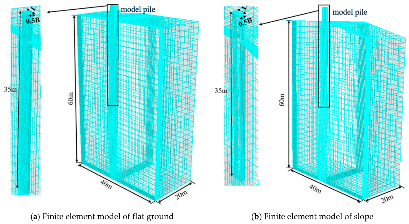
In this paper, ABAQUS 2022 is utilized to conduct numerical simulation tests on rectangular piles positioned on slopes under combined loading, enabling the consideration of the slope effect and pile–soil interactions under complex loading scenarios. Based on the strict mathematical symmetry of the structural system, half-domain models are established for both the rectangular piles and soil foundations to optimize computational efficiency. Specifically, the global plane of symmetry is chosen as the vertical X-Z plane passing through the center of the pile head. Within this parametric testing matrix, the slope gradient vector α with 0°, 15°, 20°, and 30°, the combined force loading vector β, and the strong bending axis (long side) of the rectangular pile cross-section are all aligned strictly parallel and co-planar within this identical vertical plane of symmetry. No eccentric forces, oblique loading tracks, or cross-slope topographic gradients are introduced. Consequently, out-of-plane structural shearing, non-symmetrical soil displacement fields, and torsional moments are physically non-existent, which guarantees that the half-domain formulation remains strictly valid for all evaluated analysis conditions. To investigate the bearing characteristics of rectangular piles with varying aspect ratios under a constant cross-sectional area, the pile cross-sectional area is fixed at 4 m2, with a total pile length of 35 m, an embedment depth of 30 m, and a free-standing length of 5 m. A combined load is applied to the top of the pile. To eliminate boundary constraint interference, the soil domain is designated with a transverse width of 40 m, a longitudinal length of 60 m, and a vertical depth of 60 m. For this single-pile configuration, where the maximum equivalent section width is 2 m, the lateral boundary clearance extends to 20 times the characteristic pile dimension, and the bottom bedrock clearance equals the entire pile length. This geometrical scale conforms to standard numerical modeling specifications for deep foundations, where a far-field boundary distance exceeding 10 to 12 times the foundation diameter is defined as sufficient to isolate edge stress reflections. The finite element models for both flat-ground and slope conditions are illustrated in Figure 1.
The model is meshed using C3D8R elements, comprising 40,590 soil elements and 2800 pile elements. Consequently, this specialized gradient-based mesh configuration balances both spatial accuracy and computational efficiency. Such a localized discretization control strategy for tracking high-order structural responses and peak stress localization is strictly benchmarked against successful rigorous stability verification protocols established in advanced finite element structural investigations [30]. The bottom surface of the soil model is subjected to three-way fixed constraints (i.e., the spatial constraints Ux, Uy, and Uz perpendicular to the x, y, and z axes are set to 0), while no constraints are applied to the top surfaces of the soil and the pile. The pile–soil interface interactions are modeled using the standard surface-to-surface contact algorithm in Abaqus/Standard. In the normal direction, ‘Hard’ contact behavior is enforced, which pressure-dependently allows potential gapping, sliding, and posterior pile–soil separation at the back-face under severe lateral loading. Tangential behavior is governed by the classic Coulomb friction law utilizing the Penalty method, where the interface friction coefficient μ is evaluated as tan (0.7φ) approx. 0.29 based on the soil’s internal friction angle. This implementation rigorously captures the non-linear mobilization of skin friction and soil confinement along the perimeter. To accurately capture the elastoplastic behavior of the soil, the Mohr–Coulomb model is selected as the constitutive model. The soil material parameters utilized in this study are detailed in Table 1 [31]. The pile foundation is constructed of C30 concrete, utilizing a linear elastic constitutive model; specific parameters are provided in Table 2. The pile foundation is constructed of C30 concrete, utilizing a linear elastic constitutive model with the parameters listed in Table 2. It should be noted that while assuming a linear elastic material model filters out the potential complex cracking or crushing behavior of brittle concrete under ultimate load thresholds, it effectively isolates the pure geometric efficiency of the high-aspect-ratio sections and ensures robust numerical convergence [32,33,34,35,36]. This deterministic simplification serves as a reliable baseline for macroscopic soil-pile load-transfer analysis, though the localized material non-linearity of the pile will be further calibrated in subsequent structural degradation investigations. The various analysis conditions investigated in this study are summarized in Table 3.
It should be explicitly noted that the established finite element model is positioned as a generalized parametric investigation aimed at revealing the fundamental mechanical interactions between cross-sectional geometry and slope effects. To isolate the pure geometric efficiency of the rectangular aspect ratio under combined loading, certain theoretical simplifications, such as a homogenous soil domain, dry/drained loading environments, and an idealized constitutive boundary, are intentionally adopted. This localized numerical framework serves to eliminate confounding geo-environmental variables, thereby providing a clear, trackable trajectory of the load-transfer mechanism.

2.2. Finite Element Model Analysis Steps

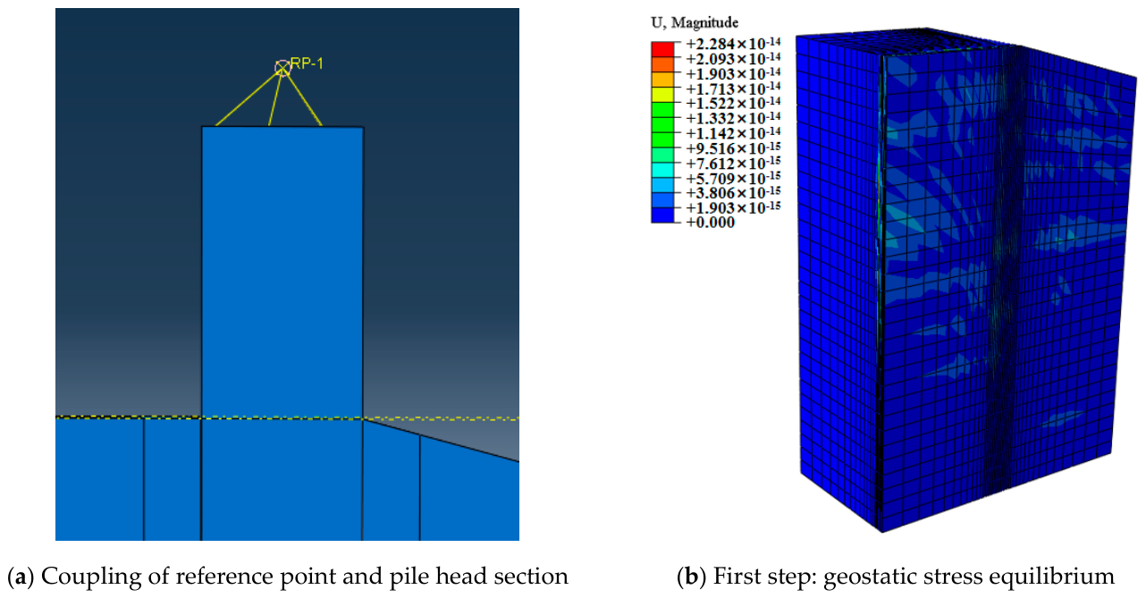
The reference point method is employed to apply the combined load. Specifically, a reference point (RP-1) is created above the pile head and coupled to the pile section to ensure uniform force transmission. To rigorously capture the path-dependent interaction behaviors, a proportional displacement-controlled loading protocol is strictly adopted in the final analysis step. By applying fixed ratios of horizontal and vertical displacement increments simultaneously, the continuous load–displacement trajectories are stably extracted. The initial loading increment is set to 0.01, with an automatic time-stepping algorithm ranging up to a maximum increment of 0.05 to guarantee numerical stability. Geometric nonlinearity (NLGEOM = ON) is fully activated across all steps to precisely simulate the high-order P-Δ effect under continuous deformation. The default Newton-Raphson solver is utilized with a strict full-matrix convergence tolerance set to 0.005.
The element birth and death technique is utilized to establish geostatic stress equilibrium. In the first step, the foundation is deactivated, and gravity is applied solely to the soil mass. In the second step, the overlapping elements between the soil and the pile foundation are deactivated, followed by the reactivation of the foundation to compute the geostatic stress equilibrium of the combined pile–soil model (Figure 2b). This procedure ensures the establishment of a realistic initial geostatic stress field within the soil mass. In real-world engineering, natural slope topographies are frequently susceptible to catastrophic instability, rain-induced seepage failure, underground drainage erosion, or extreme hydro-geological water-inrush hazards [37,38,39,40,41]. However, within the static parametric boundaries verified in this analysis, the geological matrix is explicitly restricted to an idealized homogeneous soil stratum under dry and fully drained baseline conditions to maintain sharp parametric traceability. Under this verified equilibrium phase, the maximum equivalent plastic strain (PEEQ) across the entire sloping domain remains strictly at zero, and the global nodal displacement vectors fully converge to a null magnitude of 10−14 m, objectively demonstrating that the natural slope maintains absolute baseline stability prior to the execution of external pile head loading paths.
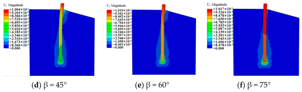
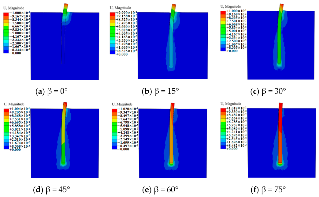
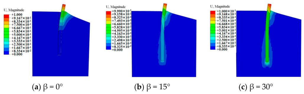
Figure 3 and Figure 4 present soil displacement contours for a rectangular pile with an aspect ratio of 1 at slope angles of 0° and 15°, respectively, under varying loading angles at the ultimate state.
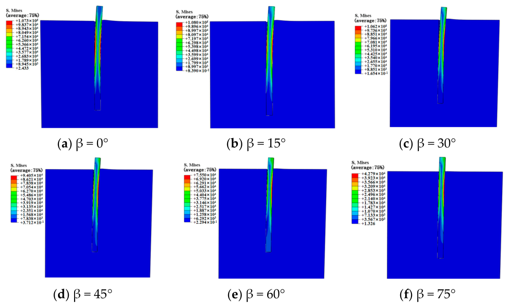
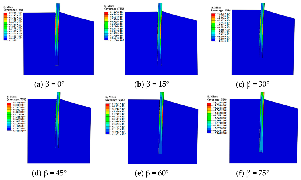
The corresponding soil equivalent stress distributions are further visualized in Figure 5 and Figure 6 to present the localized stress fields at the ultimate limit state.
To ensure technical consistency and eliminate human interpretation bias, a fixed displacement threshold criterion is implemented to define the ultimate capacity boundaries. Specifically, in accordance with generalized structural-geotechnical testing criteria and specialized literature on rectangular foundation bearing limits (Zheng, 2024 [27]), a fixed pile head displacement of 0.1 m is uniformly defined as the extraction standard for the ultimate bearing capacity. This quantitative threshold strategy aligns strictly with established parametric comparison frameworks for large-scale or multi-load foundations under equal deformation limits.

3. Analysis of Bearing Characteristics

3.1. Analysis of Ultimate Bearing Capacity Under Combined Loading

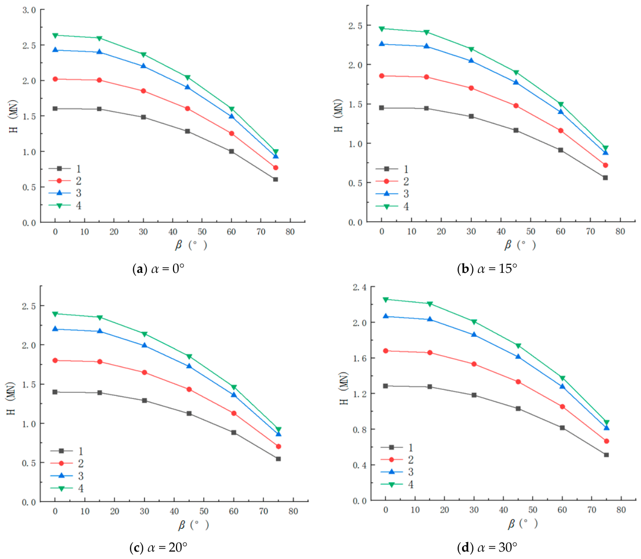
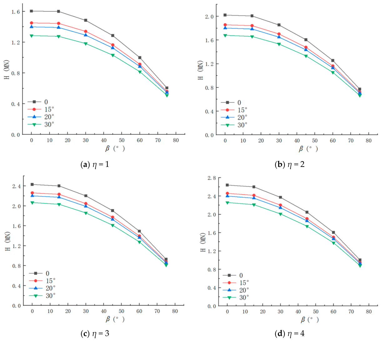
Figure 7 and Figure 8 illustrate the extracted relationships between the ultimate lateral load and loading angle (at β = 0°, 15°, 30°, 45°, 60°, and 75°) for the rectangular piles.
As indicated in Figure 7, for any given aspect ratio and slope angle, the ultimate lateral bearing capacity demonstrates a non-linear downward trend as the loading angle β increases. When β is relatively small, the decline is gradual; however, when β exceeds 45°, the lateral bearing capacity drops precipitously. This rapid decrease occurs because the increasing proportion of the vertical load significantly compresses the available space for lateral resistance mobilization. Simultaneously, optimizing the aspect ratio notably elevates the lateral bearing capacity. Taking Figure 5a as an example, under pure lateral loading on flat ground, the ultimate load of the rectangular pile with η = 4 is approximately 2.7 MN, whereas the pile with η = 1 reaches only about 1.6 MN—an increase of nearly 69%. This enhanced performance persists across all loading angles, confirming that a high aspect ratio bolsters bending stiffness and lateral stability. Moreover, as the slope angle α increases from 0° to 30°, the curves exhibit a global downward shift, reflecting a marked reduction in bearing capacity. This reduction is driven by the free slope face weakening the confinement of the soil situated in front of the pile, which in turn diminishes the maximum lateral force the pile can resist.
Comparing Figure 8a,d reveals that even on a steep 30° slope, the lateral bearing capacity of the η = 4 configuration remains significantly higher than that of the η = 1 configuration on flat ground. This suggests that within the specific numerical conditions examined, the η = 4 pile showed sufficient capacity improvement to significantly compensate for the modeled slope-induced reduction, underscoring the practical utility of rectangular cross-section optimization under these baseline topographic constraints.
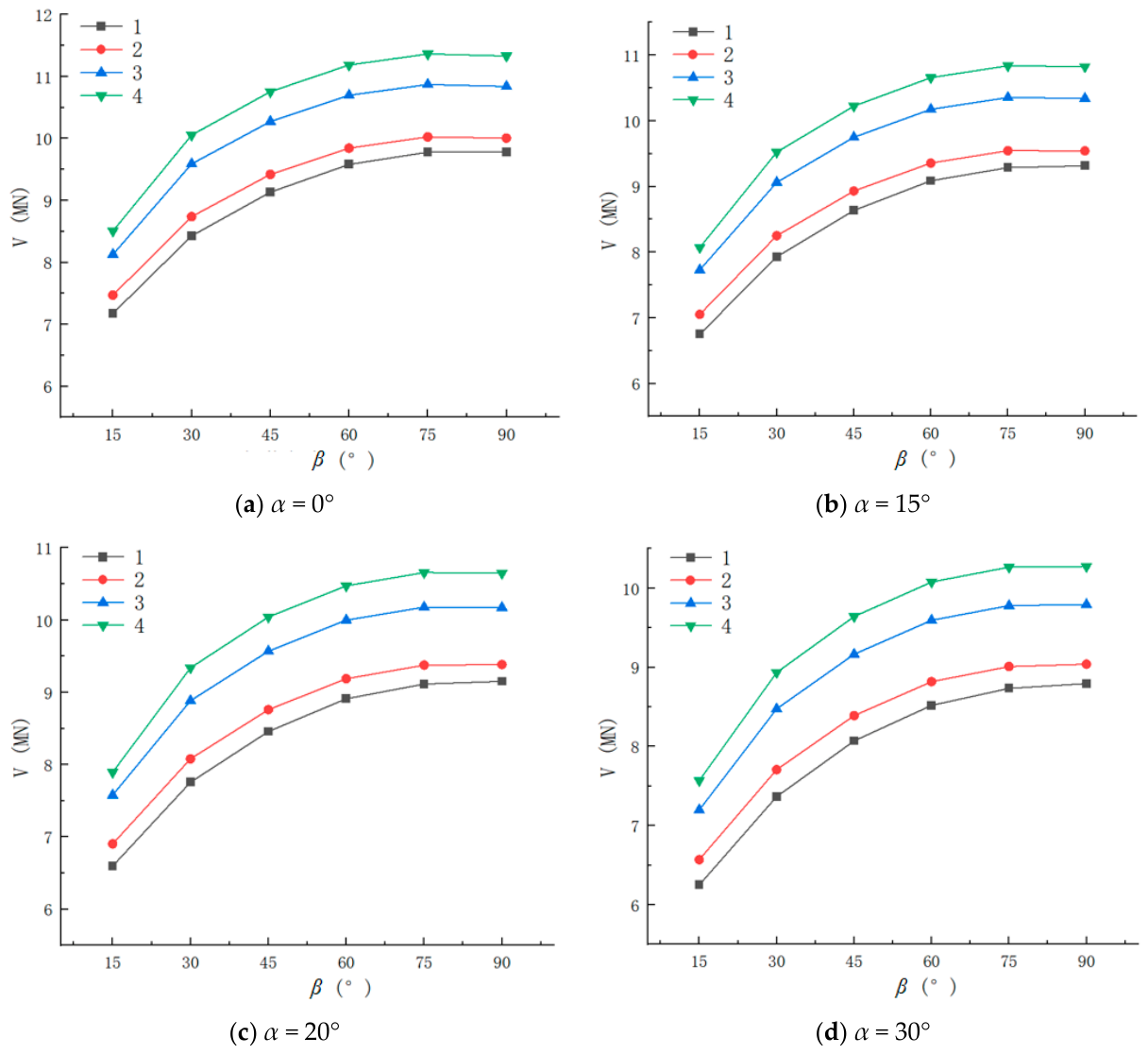
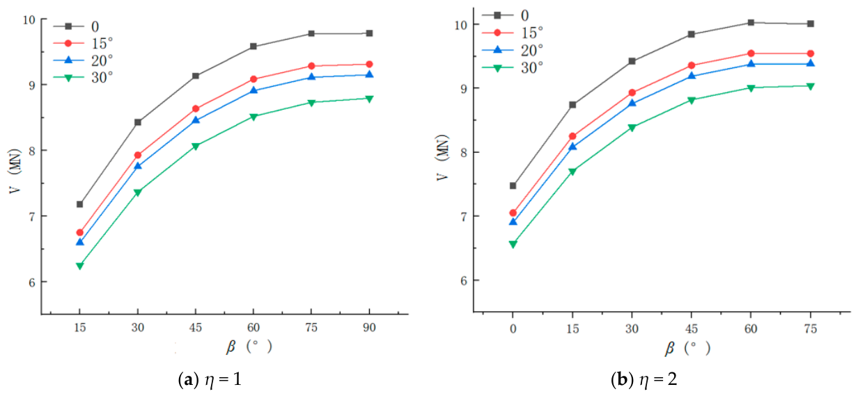
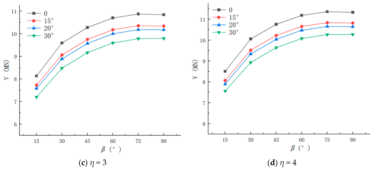
The curves depicting the variation in the ultimate vertical load of rectangular piles with loading angles (β = 0°, 15°, 30°, 45°, 60°, and 75°) are presented in Figure 9 and Figure 10. As shown in Figure 9, under various slope angles (α), the vertical bearing capacity exhibits a non-linear ascent as β increases. For β values between 15° and 60°, the rapid increase in the vertical component drives extensive mobilization of pile shaft friction and tip resistance, resulting in a dramatic surge in vertical bearing capacity. Beyond β = 60°, the curve plateaus indicate that the vertical bearing potential is approaching saturation and that the amplifying effect of β diminishes. Furthermore, the aspect ratio fundamentally enhances vertical bearing capacity. For example, at α = 0° and β = 90°, the vertical bearing capacity of the η = 1 pile is about 9.8 MN, while the η = 4 pile achieves 11.3 MN—a roughly 15% improvement. This improvement is attributed to the fact that, for a constant cross-sectional area, a larger aspect ratio yields a greater lateral surface area, allowing more skin friction to be mobilized.
Observation of Figure 10 indicates that slope topography effectively degrades vertical load-bearing performance. As the slope angle increases, the vertical bearing capacity curves shift downward uniformly. The slope’s presence lowers the effective stress level and confining pressure of the soil surrounding the pile. Specifically, on the side facing the slope’s free face, the soil’s confinement of the pile shaft weakens, leading to reduced mobilization efficiency of the skin friction, which ultimately impairs overall vertical performance.
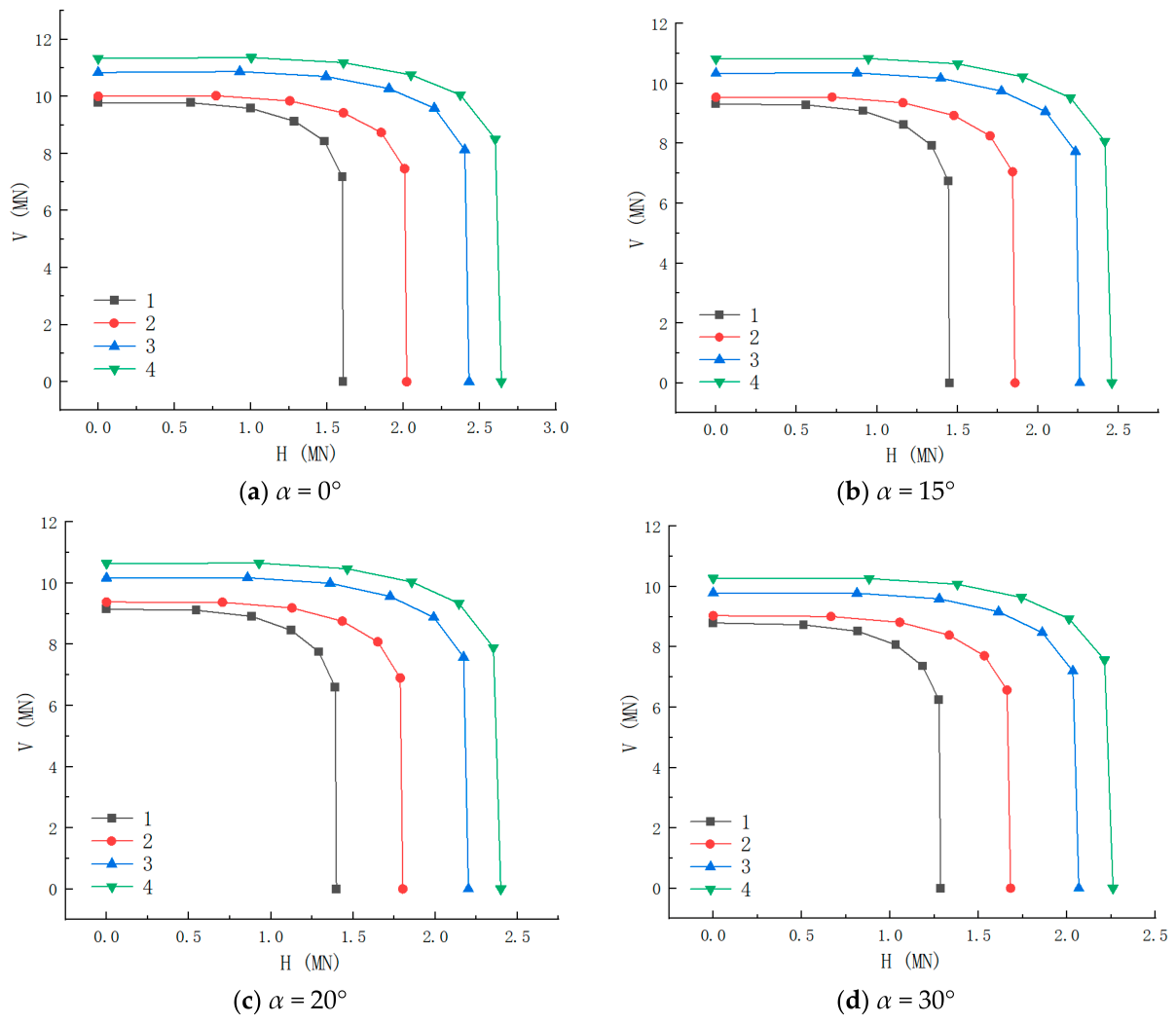
Using the ultimate horizontal and vertical loads obtained under different loading angles, H-V bearing capacity envelope curves for rectangular piles with varying aspect ratios were generated, as shown in Figure 11. The area enclosed by these envelopes represents the upper limit of the foundation’s comprehensive bearing capacity. As observed, when η increases from 1 to 4, the envelope expands globally. The expansion along the H-axis intercept (representing pure lateral bearing capacity) is the most pronounced. This is because a higher η directly enhances bending stiffness, allowing the pile to mobilize soil resistance over a broader range. The V-axis intercept also elevates as η increases, given that the expanded perimeter (at a constant cross-sectional area) bolsters the mobilization of pile shaft friction. Consequently, high-aspect-ratio rectangular piles not only improve unidirectional bearing capacities but also expand the bounds of ultimate loads under combined loading. Furthermore, as α increases from 0° to 30°, all envelope curves contract toward the origin. The contraction magnitude along the H-axis is significantly larger than along the V-axis, proving that the weakened soil confinement at the slope face deteriorates the pile’s lateral resistance more severely. Crucially, however, the envelope area for the η = 4 pile at α = 30° remains larger than that of the η = 1 pile on flat ground. This objectively indicates that the performance enhancements gained through cross-section optimization can fully negate the adverse effects of a steep 30° slope on the pile foundation’s bearing capabilities.

3.2. Bending Moment Analysis Under Combined Loading

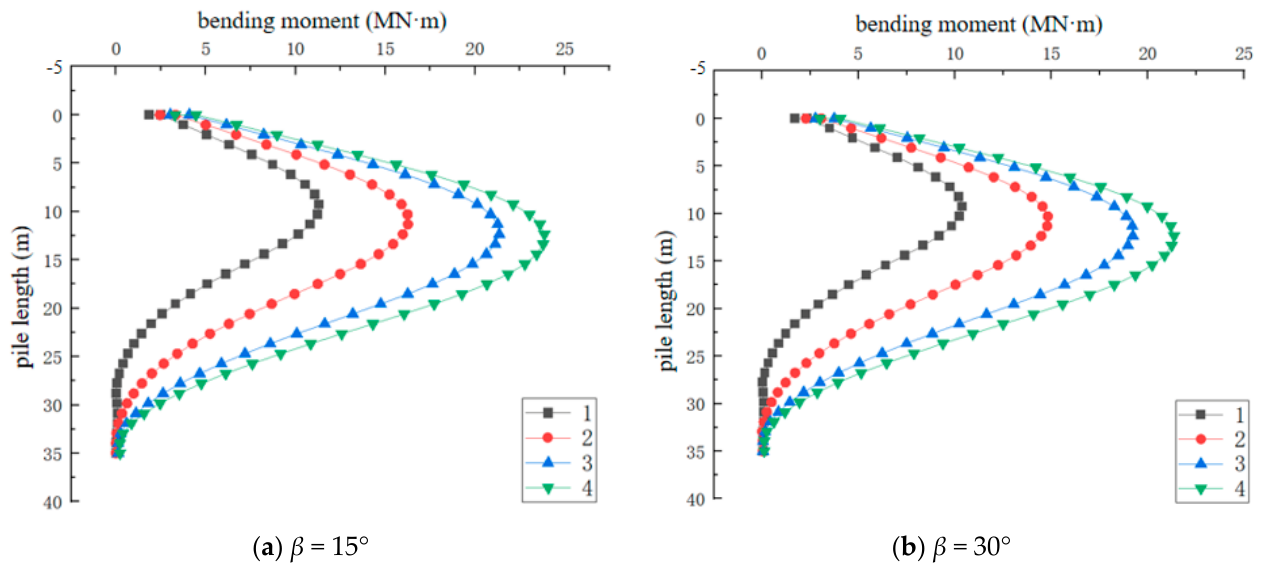
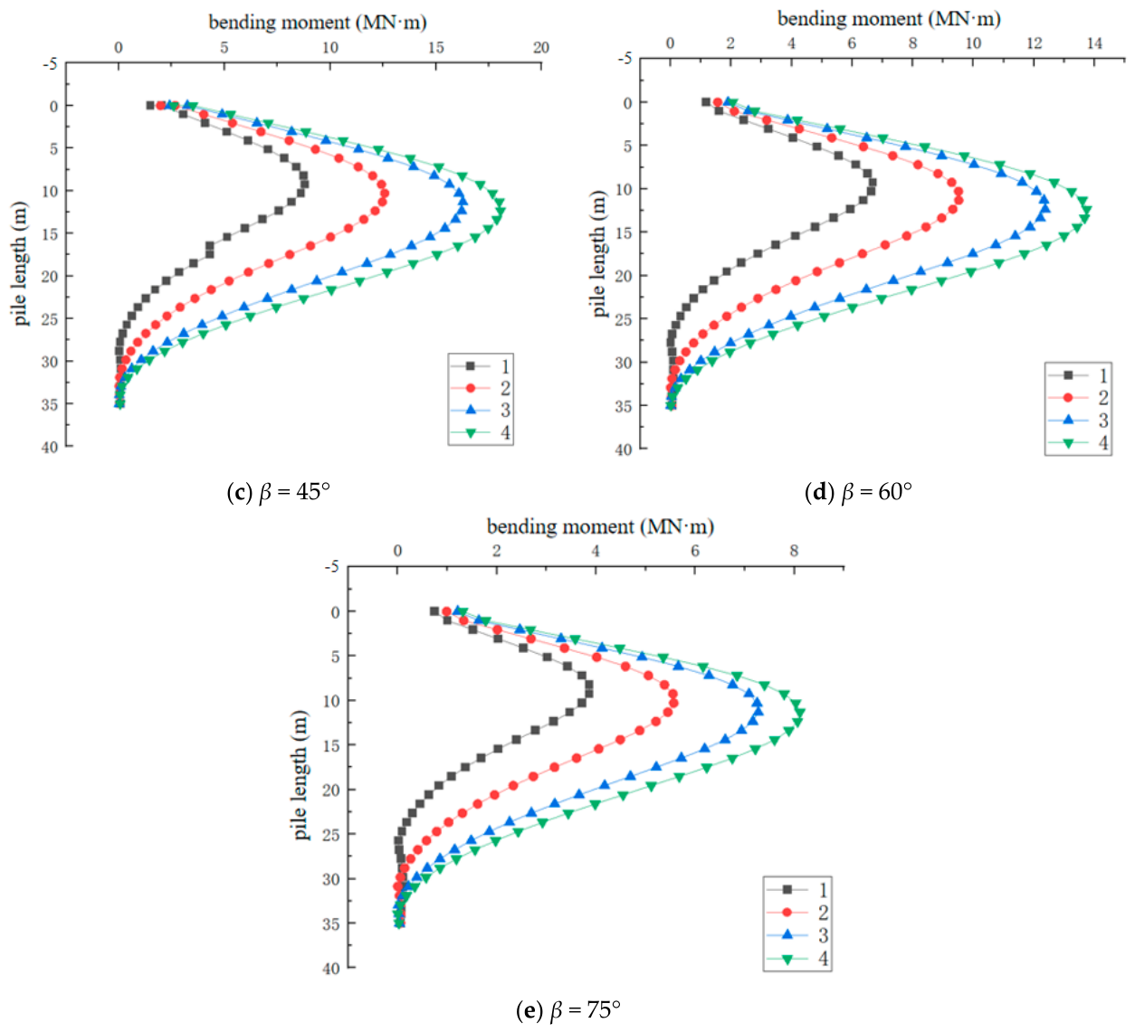
Figure 12 presents a comparison of bending moments for rectangular piles of varying aspect ratios, extracted at α = 30° for loading angles β of 15°, 30°, 45°, 60°, and 75°.
From Figure 12, it is apparent that as β increases, the absolute value of the pile bending moment exhibits a sharp downward trend. For example, for the pile configuration of α = 30° and η = 4, the maximum bending moment approaches −25 MN·m when β is 15°. When β shifts to 75°, the maximum bending moment drops to approximately −8 MN·m. In the ultimate state, as the load vector pivots vertically, the lateral force component H significantly decreases, which directly forces a massive contraction in the pile bending moments generated by lateral forces.
The calculated distributions demonstrate that the maximum bending moments and critical shear sections are consistently located within a range of 0.27 L to 0.41 L. To provide a highly precise engineering reference across different parametric variations, the exact numerical positions of these critical depth points for selected baseline aspect ratios η, slope angles, and loading paths are rigorously summarized in Table 4. Regarding the representation of internal force curves, the physical engineering dimensions are intentionally maintained rather than introducing abstract mathematical normalization. This explicit treatment successfully preserves direct industrial legibility for structural detailing while reliably isolating the geometrical optimization efficiency of the rectangular sections.

3.3. Shear Force Analysis Under Combined Loading

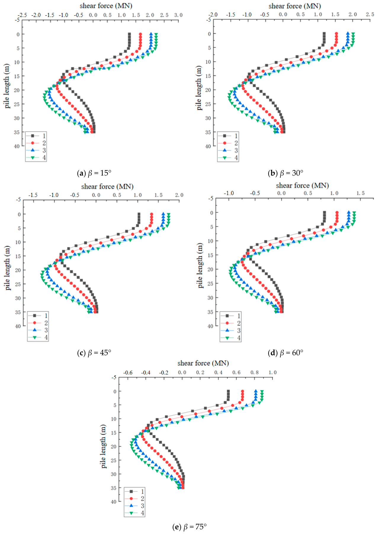
Figure 13 displays the comparison of shear forces for rectangular piles with varying aspect ratios at α = 30° for β values of 15°, 30°, 45°, 60°, and 75°.
As illustrated in Figure 13, the initial shear force at the pile head drops noticeably as β increases. As β scales from 15° to 75°, the pile head shear forces across all aspect ratios decrease notably and shrink substantially; for instance, the pile head shear force for the η = 4 pile is markedly reduced from roughly 2.25 MN to about 0.9 MN. This shift occurs because a more vertically oriented load path increases the vertical displacement component, thereby reducing the requisite lateral force. This underscores a transition in the pile foundation’s stress mechanism from lateral compression to axial load transfer, proving that the loading path firmly dictates the internal force distribution. The shear force curves adopt an “inverse S-shape.” The depth at which they first intersect the zero-axis is highly consistent across loading profiles (roughly 10 m to 15 m), correlating perfectly with the depths of maximum bending moment. This verifies that while β heavily influences internal force magnitudes, the fundamental load-transfer pathways and support mechanisms rely primarily on the inherent mechanical properties of the pile and soil, remaining largely immune to β variations.
The negative shear force localized in the middle and lower sections of the pile signifies the deep soil’s resistance to pile displacement. As β climbs, the maximum negative shear force distinctly drops (e.g., from −2.0 MN to −0.6 MN for the η = 4 pile). Additionally, when vertical forces dominate, the negative shear zone migrates slightly downward, engaging deeper soil layers to establish equilibrium. Regardless of the condition, the aspect ratio drastically affects shear distribution; the robust stiffness of the η = 4 pile enables it to mobilize a broader expanse of soil to participate in generating resistance.

3.4. Axial Force Analysis Under Combined Loading

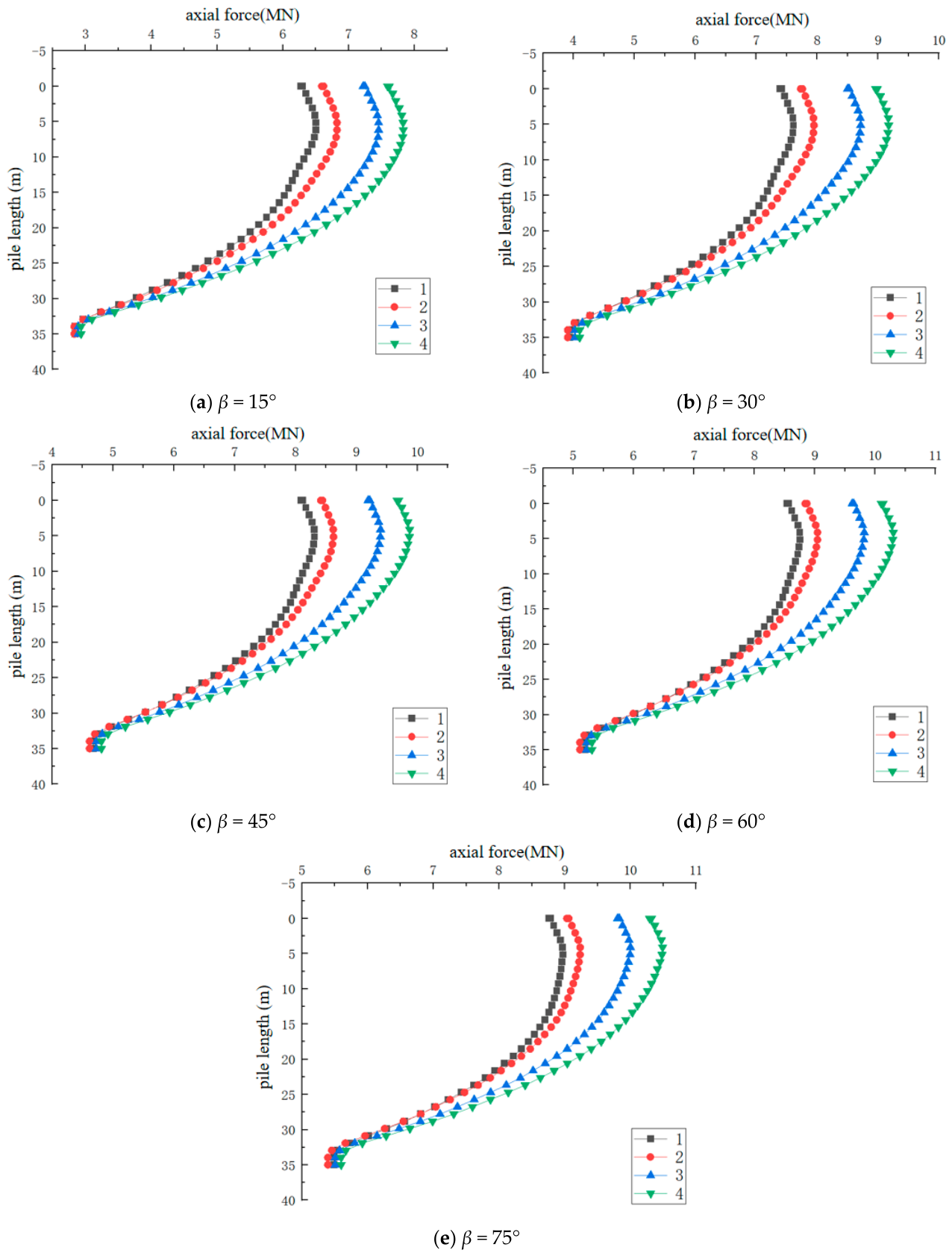
Figure 14 compares the axial forces for rectangular piles across different aspect ratios at α = 30° and β values of 15°, 30°, 45°, 60°, and 75°.
According to Figure 14, an increase in β yields an overall increase in the pile’s axial force. As the load direction aligns closer to the vertical axis, the vertical displacement component grows, compelling the pile to transmit heavier loads to deeper strata. The axial force degrades non-linearly from the pile head downward. The relatively steep decline in the upper-middle curve sections signifies that this region unloads forces predominantly via skin friction, leaving the residual axial force at the pile tip to be countered by the local tip resistance. Thus, the prevailing bearing mechanism for rectangular piles under combined loading remains skin-friction-dominant, augmented by tip resistance, and is modulated by the load component ratios. Notably, at a constant cross-sectional area, the η = 4 pile possesses an enlarged perimeter, yielding a superior pile–soil contact area. Consequently, its axial force consistently tracks higher than configurations with lower aspect ratios.

4. Conclusions

This paper utilized ABAQUS finite element simulations to analyze rectangular cross-section piles, investigating their internal stress behaviors under combined pile-head loading across diverse slope terrains and aspect ratios. By synthesizing the simulation outcomes, the following core conclusions are drawn:
(1)
Under combined loading, the lateral and vertical bearing capacities of rectangular piles display high interactivity. As β increases, lateral bearing capacity experiences a gradual decline, while the vertical component sees an increase.
(2)
Amplifying the aspect ratio significantly extends the safe operational envelope of the pile foundation, with the η = 4 pile achieving optimal performance. On flat ground, using the η = 1 pile as a baseline, escalating η from 2 to 4 elevates the maximum lateral bearing capacity by roughly 30%, 60%, and 75%, while improving vertical bearing capacity by 2.2%, 10.8%, and 15.8%. These capability increments substantially mitigate the capacity degradation incurred by slope topography.
(3)
Internal forces—bending moment, shear, and axial force—accurately blueprint the pile’s genuine stress state. In the ultimate state, the zero-shear point and the maximum bending moment point are anchored stably between depths of 0.28 L to 0.43 L below the pile head. This structural geometry is largely insulated from β fluctuations, demonstrating that the foundation’s most vulnerable stress zones are highly localized. As β surges, the pile transitions from a lateral bending/shearing paradigm to an axial compression regime.
(4)
Slope topography compromises the soil’s confining matrix. As α climbs, surrounding soil pressure plunges, skin friction deteriorates, and the V-H envelope strictly contracts. Compared to level terrain, 15°, 20°, and 30° slopes inflict maximum capacity penalties of 10.5%, 14.5%, and 25%, respectively. However, fortified by an expansive lateral surface area and superior stiffness, the η = 4 pile suppresses this decline, securing enhanced stability in slope environments and demonstrating favorable engineering applicability.
However, as a generalized parametric investigation, the evaluation envelopes and design recommendations derived herein are subject to certain idealized numerical boundaries, such as a simplified isotropic Mohr–Coulomb domain under monotonic loading paths. In real-world geotechnical engineering, the long-term response of high-aspect-ratio rectangular piles in slope topographies will inevitably be governed by site-specific granular complexities, including multi-layered soil profiles, inherent anisotropy, and hydro-geological variations. Future research incorporating targeted physical modeling and field instrumentation is highly recommended to further extend and calibrate these baseline structural parameters.

Author Contributions

Conceptualization, T.C., Z.L. and M.Z.; Methodology, T.C., C.Q. and Y.C.; Software, C.Q., Y.H. and S.X.; Validation, S.X.; Formal analysis, S.X. and Z.L.; Investigation, Y.H. and Z.L.; Resources, Y.H.; Data curation, J.X. and Y.C.; Writing—original draft, T.C. and J.X.; Writing—review & editing, J.X. and M.Z. All authors have read and agreed to the published version of the manuscript.

Funding

This work was supported by the Jiangsu Provincial Industry-University-Research Project (BY20251154) and Ningbo Municipal Transportation Science and Technology Plan Project (202402). The authors are grateful for their support.

Data Availability Statement

The original contributions presented in this study are included in the article. Further inquiries can be directed to the corresponding author.

Conflicts of Interest

Author Yunfeng Hu was employed by the company Ningbo Communications Engineering Construction Group Co., Ltd. The remaining authors declare that the research was conducted in the absence of any commercial or financial relationships that could be construed as a potential conflict of interest.

References

  1. Zhang, H.; Barrie, A.; Liang, F.; Wang, C. Numerical investigation into the response of a laterally loaded pile in coastal and offshore slopes considering scour effect. Water 2025, 17, 2032. [Google Scholar] [CrossRef] [Scilit]
  2. Perumalsamy, K.; Ranganathan, S. Single pile in cohesionless soil in sloping ground under lateral loading. Int. J. Geo-Eng. 2022, 13, 8. [Google Scholar] [CrossRef] [Scilit]
  3. Wang, Y.; Deng, R.; Guo, T.; Wang, W.; Zhang, J. Experimental study on lateral bearing capacity of pile foundation in high and steep slope area. Chin. J. Rock Mech. Eng. 2022, 41, 1466–1475. (In Chinese) [Google Scholar] [CrossRef]
  4. Wang, Y.; Liu, P.; Liu, B.; Shu, J.; Deng, H.; Zhu, M.; Li, X.; Chen, J.; Ouyang, H. Experimental study on bearing characteristics of pile-anchor foundations for floating offshore wind turbines under inclined loading. J. Mar. Sci. Eng. 2025, 13, 1890. [Google Scholar] [CrossRef] [Scilit]
  5. Malik, B.A.; Jie, S.; Zeyu, L.; Ouyang, Z.; Wang, D. Experimental investigation of suction installation behavior of caissons in loose saturated sands. Can. Geotech. J. 2025, 62, 1–21. [Google Scholar] [CrossRef] [Scilit]
  6. Diao, H.; Zhou, Z.; Wei, G.; Tian, Y.; Hu, H.; Wang, X.; Li, Q. Model Test Study on the Effect of Quasi-Rectangular Shield Tunnel Excavation on Adjacent Pile Foundation in Sand. Buildings 2026, 16, 1704. [Google Scholar] [CrossRef] [Scilit]
  7. Zhang, J.; Hu, M.; Wang, H.; Li, R.; Xu, N.; Zhang, W. Numerical simulation of bearing characteristics of single pile on slope under different bending moments. J. Henan Polytech. Univ. (Nat. Sci.) 2018, 37, 136–140+147. (In Chinese) [Google Scholar] [CrossRef]
  8. Bian, M.; Qin, S.; Peng, J.; Li, J.; Zhang, X. Exploration of the slope effect on the uplift capacity of single straight and belled piles supporting transmission towers. Front. Mater. 2023, 10, 1171601. [Google Scholar] [CrossRef] [Scilit]
  9. Jala, Y.; Sawant, V.A.; Mishra, A. Development of p-y curves from numerical study of long piles in sandy slope. Ocean Eng. 2025, 319, 120275. [Google Scholar] [CrossRef] [Scilit]
  10. Zhang, J.; Wang, X.; Wang, H.; Qin, H. Model test and numerical simulation of single pile response under combined loading in slope. Appl. Sci. 2020, 10, 6140. [Google Scholar] [CrossRef] [Scilit]
  11. Hemel, M.J.; Korff, M.; Peters, D.J. Analytical model for laterally loaded pile groups in layered sloping soil. Mar. Struct. 2022, 84, 103229. [Google Scholar] [CrossRef] [Scilit]
  12. Zhuang, P.-Z.; Sun, E.-C.; Zhang, J.-L.; Wu, Z.-X.; Yu, H.-S.; Yang, H. CASM-U: A unified critical state model for unsaturated clays and sands. Acta Geotech. 2025, 20, 211–230. [Google Scholar] [CrossRef] [Scilit]
  13. Li, X.; Ma, Z. Inherent anisotropy of aeolian sand with different bedding angles in true-triaxial tests. Eng. Geol. 2025, 356, 108272. [Google Scholar] [CrossRef] [Scilit]
  14. Zheng, Y.; Zhu, T.; Chen, J.; Shan, K.; Li, J. Relationship Between Pore-Size Distribution and 1D Compressibility of Different Reconstituted Clays Based on Fractal Theory. Fractal Fract. 2025, 9, 235. [Google Scholar] [CrossRef] [Scilit]
  15. Fang, K.; Tan, D.-Y.; Zhang, C.-C.; Shi, S.-G.; Sang, H.-W.; Shi, B. Nature-Based Profiling of Subsurface Soil Stiffness Driven by Tidal Forces. Geophys. Res. Lett. 2025, 52, e2025GL118702. [Google Scholar] [CrossRef] [Scilit]
  16. Lin, M.; Jiang, C.; Liu, P.; Pang, L. Analysis of laterally loaded offshore pile near slope in sand considering slope height. Ocean Eng. 2022, 263, 112436. [Google Scholar] [CrossRef] [Scilit]
  17. Chen, T.; Xi, S.; Qian, C.; Wang, P.; Zhu, M.; Liang, Z. Study on the soil–pile interaction of slender piles in multi-layered soil by the variational analysis method. Buildings 2024, 14, 4055. [Google Scholar] [CrossRef] [Scilit]
  18. Liu, J.; Zhu, M.; Li, X.; Ling, C.; Wang, T. The shear effect of large-diameter piles under different lateral loading levels: The transfer matrix method. Buildings 2024, 14, 1448. [Google Scholar] [CrossRef] [Scilit]
  19. Lin, C.; Wang, Z.; Shi, J.; Ma, B.; Liang, R.; Luo, X. Elasto-plastic solution for tunnelling-induced nonlinear responses of overlying jointed pipelines in sand. Tunn. Undergr. Space Technol. 2024, 152, 105953. [Google Scholar] [CrossRef] [Scilit]
  20. Fan, H.; Fu, Y.; Shen, W.; Chang, X. A coupled 3D DDA-MPM framework for soil-structure interaction modeling and its application in geotechnical hazards modeling. Eng. Geol. 2026, 364, 108591. [Google Scholar] [CrossRef] [Scilit]
  21. Zheng, Y.; Shan, K.; Xu, Y.; Chen, X. Numerical simulation of mechanical characteristics of concrete face rockfill dam under complicated geological conditions. Arab. J. Geosci. 2019, 12, 674. [Google Scholar] [CrossRef] [Scilit]
  22. Cao, G.; Zhu, M.X.; Gong, W.M.; Wang, X.; Dai, G.L. Dynamic response of vertically loaded rectangular barrettes in multilayered viscoelastic soil. Geomech. Eng. 2020, 23, 275–287. [Google Scholar] [CrossRef]
  23. Ling, C. Research on Bearing Characteristics of Novel Barrette-Type Diaphragm Wall Foundation for Onshore Wind Turbines. Master’s Thesis, Jiangsu University of Science and Technology, Zhenjiang, China, 2024. (In Chinese) [Google Scholar] [CrossRef]
  24. Xi, S.; Li, X.; Du, G.; Zhu, M.; Shi, W.; Ling, C.; Li, S. Experimental study on vertical and lateral bearing characteristics of barrette-type diaphragm wall foundation. Adv. Eng. Sci. 2024. (In Chinese) [Google Scholar] [CrossRef]
  25. Wang, T.; Zhu, M.; Du, G.; Li, X.; Shi, W. Study on vertical bearing characteristics of barrette-type diaphragm wall foundation. Chin. J. Undergr. Space Eng. 2026, 22, 246–258. (In Chinese) [Google Scholar] [CrossRef]
  26. Liu, W.; Li, H.; Weng, X.; Wang, Z.; Chen, Q.; Lei, Y.; Li, X.; Xiang, H.; Yuan, B.; Hu, W.; et al. Numerical study on the effect of pile shape and loading direction on the lateral response of displacement pile in sand. Sci. Rep. 2025, 15, 26653. [Google Scholar] [CrossRef] [Scilit] [PubMed]
  27. Zheng, W. Research on Lateral Bearing Characteristics of Rectangular Pile Foundations. Ph.D. Thesis, China Academy of Building Research, Beijing, China, 2024. (In Chinese) [Google Scholar] [CrossRef]
  28. Zhang, Z. Research on Bearing Characteristics of Rectangular Pile Group Foundations Under Combined Loading. Ph.D. Thesis, Southeast University, Nanjing, China, 2024. (In Chinese) [Google Scholar] [CrossRef]
  29. Abdulwadood, H.W.; Albusoda, B.S. Effect of pile section shape on bearing capacity under dry and saturated conditions. F1000Research 2026, 15, 275. [Google Scholar] [CrossRef] [Scilit]
  30. Shariati, M.; Raeispour, M.; Naghipour, M.; Kamyab, H.; Memarzadeh, A.; Nematzadeh, M.; Toghroli, A. Flexural behavior analysis of double honeycomb steel composite encased concrete beams: An integrated experimental and finite element study. Case Stud. Constr. Mater. 2024, 20, e03299. [Google Scholar] [CrossRef] [Scilit]
  31. Ma, F. Key technology for differential settlement control in highway reconstruction and expansion with clay subgrade widening. Transp. Sci. Technol. Manag. 2025, 6, 95–97. (In Chinese) [Google Scholar] [CrossRef] [Scilit]
  32. Brown, D.A.; Shie, C.F. Three dimensional finite element model of laterally loaded piles. Comput. Geotech. 1990, 10, 59–79. [Google Scholar] [CrossRef] [Scilit]
  33. Sawant, V.A.; Shukla, S.K. Three-Dimensional Finite Element Analysis of Laterally Loaded Piles in Sloping Ground. Indian Geotech. J. 2012, 42, 278–286. [Google Scholar] [CrossRef] [Scilit]
  34. Ho, I.H. Three-dimensional finite element analysis for soil slopes stabilization using piles. Geomech. Geoengin. 2017, 12, 234–249. [Google Scholar] [CrossRef] [Scilit]
  35. Benmebarek, M.A.; Benmebarek, S.; Rad, M.M.; Ray, R. Pile optimization in slope stabilization by 2D and 3D numerical analyses. Int. J. Geotech. Eng. 2022, 16, 211–224. [Google Scholar] [CrossRef] [Scilit]
  36. Kang, F.; Jie, P. ABAQUS Geotechnical Engineering Examples Explained in Detail; Posts & Telecom Press: Beijing, China, 2020. [Google Scholar]
  37. Zheng, Y.; Li, J.; Zheng, X.; Guo, N.; Yang, G. Pre- and post-failure behaviour of a dike after rapid drawdown of river level based on material point method. Comput. Geotech. 2024, 170, 106269. [Google Scholar] [CrossRef] [Scilit]
  38. Wu, L.; He, B.; Peng, J. Analysis of Rainfall-Caused Seepage into Underlying Bedrock Slope Based on Seepage Deformation Coupling. Int. J. Geomech. 2024, 24, 04024045. [Google Scholar] [CrossRef] [Scilit]
  39. Safa, M.; Sari, P.A.; Shariati, M.; Suhatril, M.; Trung, N.T.; Wakil, K.; Khorami, M. Development of neuro-fuzzy and neuro-bee predictive models for prediction of the safety factor of eco-protection slopes. Phys. A 2020, 550, 124046. [Google Scholar] [CrossRef] [Scilit]
  40. Peng, S.; Li, C.; Luo, G.; Li, Y.; Pan, H.; Cao, H.; Liang, S. Laboratory investigation effects of control measures for leakage-induced erosion on seepage interactions in defective underground structures. Tunn. Undergr. Space Technol. 2025, 161, 106593. [Google Scholar] [CrossRef] [Scilit]
  41. Zhang, G.-H.; Xie, Z.-Z.; Zhang, B.-W.; Jiao, Y.-Y.; Zou, J.-P.; Wu, J.-Q.; Xiong, F.; Tang, Z.-C. Sources of high-temperature water and gas inrush during tunnel excavation: A case of Bangfu tunnel in Southwest China. J. Rock Mech. Geotech. Eng. 2024, 16, 5027–5049. [Google Scholar] [CrossRef] [Scilit]
Figure 1. Finite element model of rectangular piles.
Buildings 16 02483 g001
Figure 2. Load application and geostatic stress equilibrium.
Buildings 16 02483 g002
Figure 3. Soil displacement contours under different loading angles for rectangular piles at a slope angle of 0°.
Buildings 16 02483 g003
Figure 4. Soil displacement contours under different loading angles for rectangular piles at a slope angle of 15°.
Buildings 16 02483 g004aBuildings 16 02483 g004b
Figure 5. Soil von Mises stress contours under different loading angles for rectangular piles at a slope angle of 0°.
Buildings 16 02483 g005
Figure 6. Soil von Mises stress contours under different loading angles for rectangular piles at a slope angle of 15°.
Buildings 16 02483 g006
Figure 7. Relationship between lateral bearing capacity and loading angle of rectangular piles with different aspect ratios.
Buildings 16 02483 g007
Figure 8. Relationship between lateral bearing capacity and loading angle of rectangular piles under different slope angles.
Buildings 16 02483 g008
Figure 9. Relationship between vertical bearing capacity and loading angle of rectangular piles with different aspect ratios.
Buildings 16 02483 g009
Figure 10. Relationship between vertical bearing capacity and loading angle of rectangular piles under different slope angles.
Buildings 16 02483 g010aBuildings 16 02483 g010b
Figure 11. Bearing capacity envelopes of rectangular pile foundations with different aspect ratios.
Buildings 16 02483 g011
Figure 12. Comparison of bending moments of rectangular piles at a slope angle of 30°.
Buildings 16 02483 g012aBuildings 16 02483 g012b
Figure 13. Comparison of pile shear forces of rectangular piles at a slope angle of 30°.
Buildings 16 02483 g013
Figure 14. Comparison of pile axial forces of rectangular piles at a slope angle of 30°.
Buildings 16 02483 g014
Table 1. Soil parameters.
Soil TypeElastic Modulus (kPa)Poisson’s RatioInternal Friction Angle (°)Dilation Angle (°)Cohesion Yield Stress (kPa)Effective Unit Weight (kN/m3)
Silty clay52,0000.42351816
Table 2. Physical parameters of piles.
Embedment Depth (m)Pile Length (m)Elastic Modulus (kPa)Effective Unit Weight (kN/m3)Poisson’s Ratio
30353.15 × 107250.3
Table 3. Model analysis conditions.
VariablesAspect Ratio (η)Slope Angle (α)Loading Angle (β)
Conditions1, 2, 3, 40°, 15°, 20°, 30°0°, 15°, 30°, 45°, 60°, 75°, 90°
Table 4. Critical depth locations for maximum bending moments under diverse configurations (α = 30°).
Aspect Ratio (η)Loading Angle (β)Peak Location z (m)Critical Depth (z/L)
115°10.150.29
30°9.800.28
45°9.800.28
60°10.150.29
75°10.500.30
215°11.900.34
30°11.200.32
45°11.200.32
60°11.550.33
75°12.250.35
315°13.650.39
30°12.950.37
45°12.950.37
60°12.300.38
75°14.000.40
415°14.700.42
30°14.350.41
45°14.350.41
60°14.700.42
75°15.050.43
Disclaimer/Publisher’s Note: The statements, opinions and data contained in all publications are solely those of the individual author(s) and contributor(s) and not of MDPI and/or the editor(s). MDPI and/or the editor(s) disclaim responsibility for any injury to people or property resulting from any ideas, methods, instructions or products referred to in the content.