Article

Experimental Study on the Withdrawal Resistance of Self-Tapping Screws in Cross-Laminated Timber Considering Material Aging Effects

Department of Timber Structures, College of Materials Science and Engineering, Nanjing Forestry University, No. 159 Longpan Road, Nanjing 210037, China
*
Author to whom correspondence should be addressed.
Buildings 2026, 16(11), 2208; https://doi.org/10.3390/buildings16112208
Submission received: 24 April 2026 / Revised: 26 May 2026 / Accepted: 28 May 2026 / Published: 30 May 2026
(This article belongs to the Special Issue Performance and Analysis Methods of Timber Structures)

Abstract

Cross-laminated timber (CLT), an engineered timber product with distinctive features, has significantly broadened the applicability of timber structures. The self-tapping screws (STSs) with excellent anchorage performance have become one of the primary connectors used in CLT structures. However, the long-term withdrawal resistance is susceptible to environmental factors such as temperature and humidity fluctuations, which may lead to reduced CLT density and corrosion-induced degradation of the steel components. These effects represent a critical life-cycle challenge to the structural integrity and safety of timber connections. This study aims to investigate the withdrawal resistance of STSs in CLT under material aging effects. To achieve this, a two-step experimental program was designed. First, the effects of two artificial accelerated aging methods (ASTM D1037 and improved version of ASTM D1037) on the withdrawal resistance of STSs in glued laminated timber (glulam) were compared to validate the feasibility of the improved protocol. This comparison was necessary to ensure that the improved protocol produces a degradation pattern without altering the failure mechanism. Subsequently, a series of CLT specimens with embedded STSs were subjected to 0, 3 and 6 aging cycles to investigate the withdrawal behavior including aging characterization, failure modes, load–displacement curves, withdrawal capacity, and stiffness. The results indicate that the failure mode of CLT joint with STSs under the improved aging scheme was the consistent pull-out of STSs, identical to that observed in the glulam, confirming mechanistic consistency. After three and six aging cycles, the normalized withdrawal capacity retention rates were 104.98% and 95.36%, respectively. The stiffness is more significantly affected by aging. The corresponding normalized stiffness retention rates were 85.60% and 80.94%, respectively. As the number of aging cycles increased, the occurrence of wood fiber tearing became more pronounced and the ratio of the corresponding load to the peak load decreased. Furthermore, ensuring adequate distance from the vertical glue layer was found to lead to greater long-term resilience and withdrawal capacity.

1. Introduction

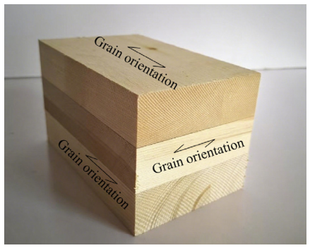
Attributing to renewability, ease of processing and relatively low carbon emissions, timber structures are increasingly recognized as a key type of green architecture. The strength of timber in the transverse direction is significantly lower than that in the longitudinal direction. Consequently, the longitudinal direction serves as the primary load-bearing direction for both solid and engineered wood members. Cross-laminated timber (CLT) is produced by bonding an odd number of timber layers together (Figure 1). These layers are arranged at a 90° angle, alternating between the transverse and longitudinal directions [1]. CLT demonstrates superior mechanical properties in both directions. It offers a broader range of applications compared to other engineered timber products [2].
In recent years, the global development of tall wooden buildings has accelerated with an increasing number of structures incorporating CLT [1,2,3,4]. Noteworthy examples include the Brock Commons Tallwood House at the University of British Columbia, the Mjøstårnet building in Norway, the 10-storey Forte Apartments in Melbourne, and the T3 building in the United States [3,4]. CLT joint connections are crucial components in prefabricated multi-story frame buildings. Their performance directly impacts bearing capacity, stiffness, ductility, and energy dissipation. These factors collectively influence the safety and reliability of the overall structure [5,6,7].
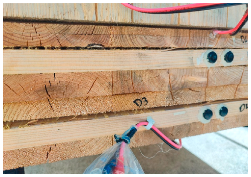
As the service life of CLT structures extends, long-term alternating changes in temperature and humidity can degrade the mechanical properties of CLT [8,9,10] (Figure 2). As shown in Figure 2, delamination, drying cracks, and deformation are caused by repeated wetting and drying on the CLT end-grain surface. The changes in the environmental factors also reduce the connection performance of the CLT joints, thereby affecting structural durability and safety. Consequently, evaluating the long-term performance of CLT materials and joint connections under varying environmental conditions has become a critical focus of research [11,12,13]. The fluctuations of moisture content in CLT under different environmental conditions significantly influence the long-term withdrawal resistance of self-tapping screws (STSs) [14]. Therefore, investigating the effects of aging on the mechanical performance of CLT joints is essential. This analysis is crucial for ensuring accurate safety assessments of structural performance.
Recent studies have examined CLT connections under moisture change, screw withdrawal, and biological degradation. Moisture content and loading rate can affect the axial withdrawal capacity of screws in CLT [15]. Wood density, screw diameter, and penetration length are also important factors for the withdrawal capacity and strength of STSs in CLT [16]. The design of STSs has also been studied for Korean larch and red pine CLT. The main factors included screw material, thread angle, and thread shape [17]. Some studies have focused on fungal decay. Fungal decay can reduce the load-carrying capacity, stiffness, energy dissipation, and ductility of CLT connection assemblies [18]. A related dataset with 560 fungal-decayed CLT connection specimens was also reported [19]. Biodeterioration has also been considered in the modeling of code-compliant CLT lateral connections [11]. These studies show that environmental degradation can affect the mechanical performance of CLT connections. However, most existing studies focused on biological degradation, lateral connections, cyclic behavior, or moisture effects. Few studies have focused on accelerated aging methods for STS withdrawal connections in CLT. In addition, the effect of the screw-to-vertical-glue-line distance (STVGD) after aging remains unclear.
The aging methods applicable to CLT joints are crucial in the context of aging studies. However, standardized guidelines specifically addressing aging methods for CLT are limited. Furthermore, research on the aging performance of CLT joints remains sparse. Several aging methods have been utilized by researchers, including the artificial accelerated aging method in the BS EN 1087-1 [20], the aging test cycle in the EN 927-6 [21], and the six-cycle accelerated aging protocol in the ASTM D1037 [22]. The ASTM D1037 method simulates real environmental conditions by subjecting wood to six cycles of specific temperature and humidity treatments [22]. This rigorous method is extensively used to evaluate the quality and aging resistance of engineered wood products, although it is time-consuming [23]. The BS EN 1087-1 method, which incorporates a boiling process, is particularly effective for assessing the aging resistance of bamboo composites. However, when applied to laminated materials, this method poses an increased risk of delamination compared to natural aging [24]. The EN 927-6 aging test cycle uses fluorescent lamps to simulate ultraviolet radiation. Additionally, the method utilizes condensation and water spraying to accelerate the aging process. It is primarily used to predict the performance and durability of wood coatings under outdoor conditions [25].
Experts have confirmed that glulam exhibits similar mechanical performance under both the standard and modified ASTM D1037 aging methods [26,27]. Studies indicate that the modified ASTM D1037 method retains testing accuracy while significantly reducing processing time and enhancing efficiency. This method proves valuable for rapid evaluation of material durability. Furthermore, it offers a useful reference for assessing the aging performance of glulam connections.
Despite the above progress, the withdrawal behavior of STSs in CLT after environmental aging remains poorly understood. Existing accelerated aging methods are mainly used to evaluate the durability of wood-based materials, panels, coatings, or composite products [20,21,22,23,24,25]. They are not specifically developed for assessing the mechanical degradation of STS connections in CLT. Thus, their applicability to the withdrawal capacity, stiffness retention, and failure mechanism of aged CLT connections still needs to be verified.
Existing studies have mainly considered moisture variation, screw diameter, insertion angle, material density, embedment depth, and gaps between lamellas [14,28]. The influence of local boundary conditions around screws has also been reported. For example, end distance and screw spacing can affect the stiffness, load-carrying capacity, and failure mode of timber or CLT screw connections [29,30]. However, the STVGD has rarely been considered. This factor may become important after aging. Aging-induced cracking or delamination along the vertical glue line may create a weakened internal boundary. In this case, the vertical glue line may play a role similar to an internal edge or end boundary. It may affect crack development and stress transfer around the screw.
Given the above statements, the withdrawal resistance of STSs in CLT considering material aging effects needs to be investigated. The main objectives were to evaluate the applicability of the improved ASTM D1037 aging method and to clarify the role of the STVGD in the withdrawal behavior of STSs in CLT. First, withdrawal tests of STSs in glulam were conducted using the standard and improved aging methods. Their effects on aging characteristics, failure mode, withdrawal capacity, and stiffness were compared. Then, the improved aging method was applied to CLT specimens with embedded STSs. The failure modes, load–displacement curves, withdrawal capacity, stiffness, and the effect of the STVGD were analyzed. The results provide experimental evidence for the rapid durability assessment of STS connections in CLT.

2. Comparative Study on the Withdrawal Performance of Self-Tapping Screws in Glulam Under Two Aging Methods

2.1. Research Plan

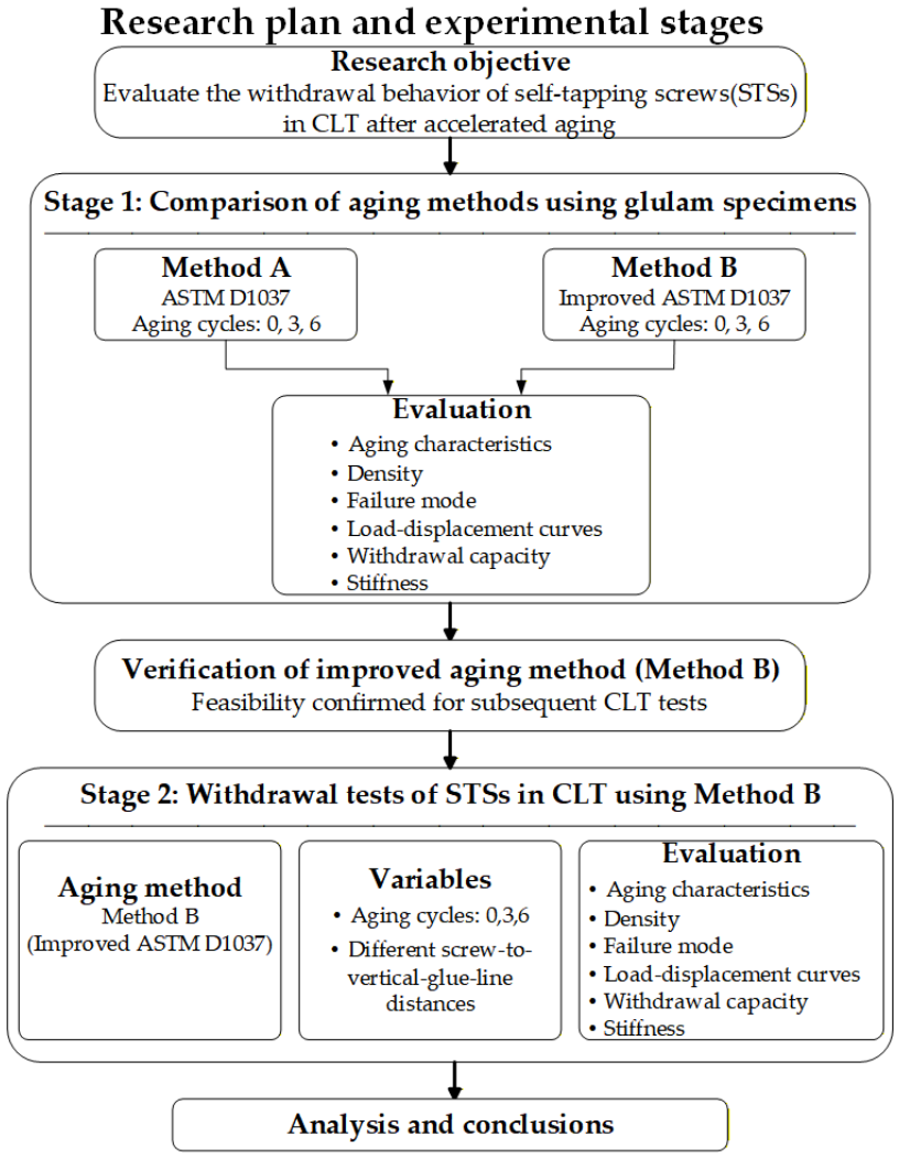
The overall research plan is shown in Figure 3. The experimental program consisted of two stages. In the first stage, glulam specimens were used to compare the standard ASTM D1037 aging method and the improved aging method. In the second stage, the improved aging method was applied to CLT specimens. The effects of aging cycles and STVGD on withdrawal behavior were then investigated.

2.2. Aging Protocols

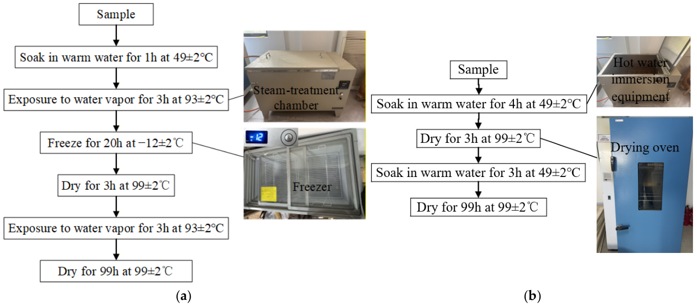
The specific procedures for both the ASTM D1037 six-cycle accelerated aging method (Method A) and the improved ASTM D1037 method (Method B) are outlined below (Figure 4).
Method A was conducted for 0, 3, and 6 cycles. Each cycle consisted of the following steps: soaking the specimen in hot water at (49 ± 2 °C) for 1 h, steam treatment for 3 h (93 ± 3 °C), freezing for 20 h (−12 ± 3 °C), drying for 3 h (99 ± 3 °C), steam treatment for 3 h (93 ± 3 °C), and drying for 18 h (99 ± 2 °C). After completing six conditioning cycles, the specimen was conditioned at (20 ± 3 °C) and relative humidity (65 ± 1)% for 48 h before mechanical property testing.
Method B also involves 0, 3, or 6 cycles. Each cycle consisted of the following steps: soaking the specimen in hot water at (49 ± 2 °C) for 4 h, drying for 3 h (99 ± 3 °C), soaking the specimen in hot water at (49 ± 2 °C) for 3 h, and drying for 18 h (99 ± 3 °C). After the completion of each cycle, the specimen underwent tempering treatment identical to that of Scheme A.
A comparison of the two methods reveals that the procedures in method A are more complex than those in Method B. Method A includes exposure to water vapor and freezing. This enables a more comprehensive simulation of environmental changes, leading to a more representative aging effect. However, method A requires more steps, has more intricate procedures, and involves a longer testing period. In contrast, method B features simplified steps, is easier to implement, and requires a shorter testing period. It offers advantages in terms of time efficiency and resource savings, making it more suitable for rapid aging assessments within a limited timeframe.
The freezing step may have limited influence on some residual mechanical properties of wood-based panels [31]. Method B omits the freeze–thaw stage included in the standard ASTM D1037 procedure and retains the repeated hot-water soaking and high-temperature drying processes. These processes can induce moisture gradients, swelling–shrinkage deformation, internal stress development, glue-line damage, and degradation at the screw–wood interface during accelerated aging. These mechanisms are closely related to the withdrawal behavior of STSs. Consequently, Method B was designed to activate the dominant aging mechanisms affecting STS withdrawal performance, while reducing the testing duration. Its comparability with Method A was further evaluated through the glulam withdrawal tests in Section 3.1.

2.3. Glulam Withdrawal Tests

2.3.1. Specimen Design for Glulam Withdrawal Tests

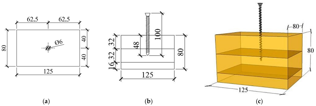
The Douglas fir glulam used in the self-tapping screw withdrawal tests was produced by Nantong Jiazhu Construction Technology Co., Ltd., Nantong, China. The average density and moisture content of the glulam were 0.55 g/cm3 and 10.4%, respectively. The self-tapping screws, with diameters of 6 mm and lengths of 100 mm, were supplied by Shanghai Meigu Fasteners Co., Ltd., Shanghai, China. The mechanical properties of the screws are detailed in Table 1. The experiment was divided into five groups based on the aging methods (methods A and B) and the number of aging cycles (0, 3, and 6). One group consisted of unaged specimens (group A/B-0), two groups (groups A-3 and A-6) were subjected to aging Method A, and two groups (groups B-3 and B-6) were subjected to aging Method B. Each group contained six specimens. The specimen dimensions (80 × 80 × 125 mm) and the screw embedment depth (lp = 48 mm) were selected with reference to Eurocode 5 [26], which provides size recommendations for small-scale withdrawal testing, as well as previous studies on the withdrawal behavior of self-tapping screws in timber [32]. In addition, six specimens were fabricated for each test group to ensure statistical reliability, following common practice in withdrawal resistance research. These standards and prior studies collectively form the basis for the design and fabrication of the test specimens in this study. The specific design parameters for the specimens and a schematic diagram of the components are shown in Table 2 and Figure 5, respectively. Table 1 presents the specimen identifiers in the format of the aging method-number of cycles. For example, “A-6” denotes the specimen aged using method A with six aging cycles.
According to the European Standard EN 1995-1-1:2004 (Eurocode 5: Design of Timber Structures) [26], pre-drilling is required when the wood density exceeds 0.5 g/cm3 or when the screw diameter exceeds 8 mm. The Meigu product manual [33] recommends a pre-drilling hole diameter of 4 mm for STSs with a diameter of 6 mm. Before screw installation, the screw positions were marked according to the designed layout. Pilot holes with a diameter of 4 mm were drilled for the 6 mm STSs according to the manufacturer’s recommendation. The screws were then installed to the designed embedment depth of 48 mm.
The equivalence of the two aging methods was verified in the mechanical properties of glulam [31]. Glulam was used as a preliminary reference system to compare the two aging methods in this withdrawal test. It has a relatively regular unidirectional laminated structure. This can reduce the interference of CLT-specific factors, such as orthogonal layers and vertical glue lines. The withdrawal performance of STSs in CLT was further investigated through the subsequent CLT tests.

2.3.2. Loading Procedure for Glulam Withdrawal Tests

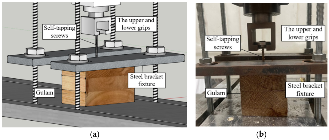
The withdrawal tests were conducted in the Mechanics Laboratory of the College of Material Science and Engineering, Nanjing Forestry University. A UTM5105 electromechanical universal testing machine (Shenzhen Sansi Zongheng Technology Co., Ltd., Shenzhen, China) was used for loading. The maximum capacity was 100 kN, and the accuracy grade was 0.5. The machine power and voltage were 1.5 kW and 380 V, respectively. The glulam specimen was rigidly fixed using a steel bracket assembly, with both ends clamped by the upper and lower grips of the universal testing machine. The test setup and apparatus are shown in Figure 6. The loading rate was set to 3 mm/min [34]. Loading was applied until 50% of the peak load was reached, at which point the process was terminated.
In this study, the loading protocol was mainly designed to determine the withdrawal capacity and stiffness of STS connections. Loading was applied until 50% of the peak load was reached, at which point the process was terminated. The lack of a complete post-peak response until full screw withdrawal may compromise the evaluation of ductility and energy dissipation.

2.4. CLT Withdrawal Tests

2.4.1. Accelerated Aging Procedure for CLT Specimens

This study employed the improved version of the ASTM D1037 aging method (Scheme B) to accelerate the aging of CLT. The aging cyclic procedure is illustrated in Figure 4.

2.4.2. Specimen Design for CLT Withdrawal Tests

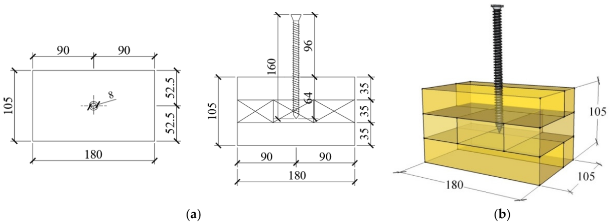
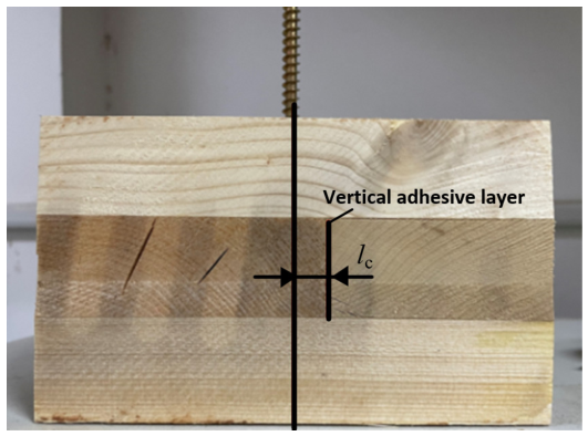
The CLT used in tests was produced by Shandong Dingchi Wood Industry Co., Ltd., Penglai, China. The wood species employed is spruce pine-fir (SPF). During production, the factory ambient temperature was 12 °C, and the moisture content of the SPF timber was 9.78%. The spruce–pine–fir (SPF) lumber used in the CLT was imported from Canada and visually graded as IIc. The average oven-dry density of the CLT was 0.42 g/cm3, determined according to GB/T 1927.5-2021 [32]. All CLT panels in this study were manufactured using one-component polyurethane (PUR) structural adhesive. For the cross layers, several narrow lamellas were edge-glued along their narrow faces to form wider layers before cross-lamination [33]. The adhesive applied to the vertical (edge-grain) surfaces ensures panel width and dimensional stability, promotes uniform stress transfer between lamellas, and enhances durability by preventing moisture ingress and delamination. Under cyclic temperature and humidity, these vertical adhesive layers may also become preferential sites for cracking or delamination due to differential shrinkage between the PUR adhesive and the surrounding wood. STSs with a diameter of 8 mm and a length of 160 mm were tested in this section because this size is widely used in practical connections. STSs were also provided by Shanghai Meigu Fasteners Co., Ltd. The mechanical properties of the screws are presented in Table 3. The experiment was conducted with five groups, each containing six specimens. Among these, groups B-3-X and B-6-X were designed as supplementary groups with the same distance from STS to the vertical adhesive layer of CLT (Figure 7). The vertical glue adhesive layer in CLT after aging is prone to cracking. Furthermore, such cracks can severely influence the structural integrity of the test specimens and compromise the withdrawal performance of STSs in CLT, leading to potentially inaccurate results. The distance between the screw and the vertical adhesive layer in groups B-3-X and B-6-X was set equal to that of the unaged group (B-0) to minimize the influence of aging-induced glue-line cracking on withdrawal performance and to ensure a controlled comparison among aging cycles. To mitigate the impact of cracking on withdrawal performance, two groups of specimens (B-3-X and B-6-X) were used for comparison. Both groups had the same distance, lc, from the screw to the vertical adhesive layer. The schematic diagram of the CLT withdrawal specimens and the specific design parameters are shown in Figure 8 and Table 4, respectively. The recommended diameter of the pre-drilling hole for the 8 mm self-tapping screws is 5 mm [26,34]. Before screw installation, the CLT panels were cut into withdrawal specimens with the designed dimensions. The screw positions were marked according to the required distance from the vertical glue line. Pilot holes with a diameter of 5 mm were drilled for the 8 mm STSs according to the manufacturer’s recommendation. The screws were then installed to the designed embedment depth of 64 mm.

2.4.3. Loading Procedure for CLT Withdrawal Tests

The CLT withdrawal tests were conducted using the same testing machine and loading rate as in the glulam withdrawal tests in Section 2.3 [35] in Figure 6b.

2.5. Statistical Analysis

Before analyzing the experimental results, statistical indicators were used to describe the reliability of the withdrawal test results. For each withdrawal test group, the mean value, standard deviation, coefficient of variation, and 95% confidence interval were calculated. The 95% confidence interval was calculated according to Equation (1).
    CI = x   - ±   t 0.975 ,   n 1 s n
where x - is the mean value, s is the standard deviation, n is the number of specimens, and t 0.975 ,   n 1 is the critical value of the t-distribution. For six specimens per group, t 0.975 ,   n 1 = 2.571 . The confidence interval was used to assess the reliability of the mean value.
To further evaluate the relative precision of the mean value, the relative standard error (RSE) was also calculated. The RSE was calculated according to Equation (2). The standard error of the mean describes the precision of the sample mean as an estimate of the population mean [36].
RSE = SE x - × 100 % = s x - n × 100 % = CoV n
where SE is the standard error of the mean, and CoV is the coefficient of variation. The RSE expresses the standard error as a percentage of the estimated mean value. A smaller RSE indicates lower relative uncertainty and higher relative precision of the estimated mean. In this study, the RSE was used as a supplementary statistical indicator together with the coefficient of variation and the 95% confidence interval.

3. Results

3.1. Comparison of Aging Effects on Glulam Withdrawal Specimens

3.1.1. Aging Characteristics

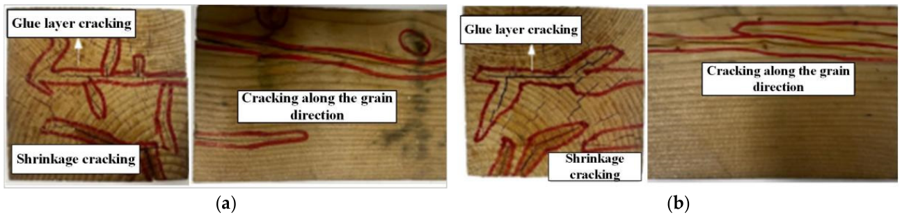
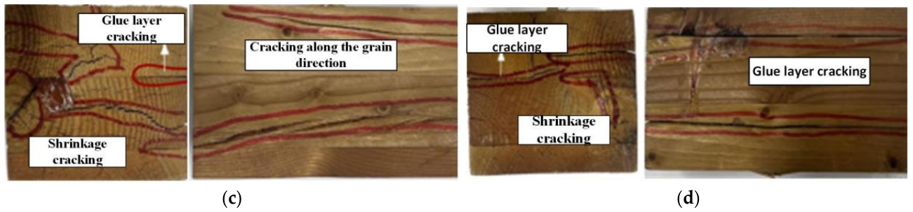
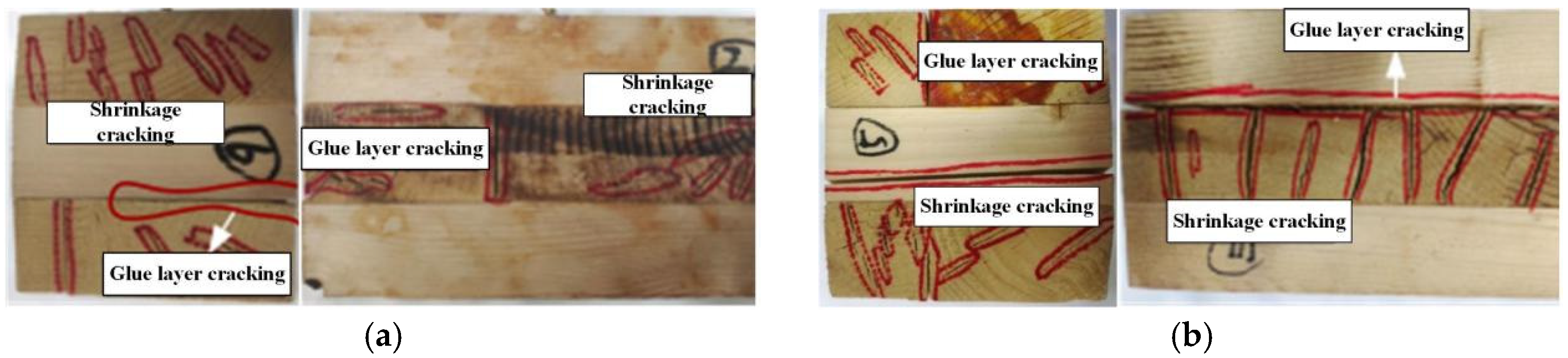
The macroscopic characteristics of the glulam withdrawal specimens after aging include deformation, cracking, and adhesive degradation within the glue layer. Figure 9 presents the observed characteristics of aged specimens. Each layer of the glulam specimen deformed due to dimensional and volumetric changes. These changes are primarily caused by hygroscopic shrinkage and swelling. Cracking observed after aging was classified into two types: glue layer cracking and shrinkage cracking. Drying-induced internal stresses in the wood resulted in tension in the outer layers and compression in the inner layers. When the tensile stress in the surface layers exceeded the transverse tensile strength of the wood, crack initiation occurred through tissue separation along the grain. Initially, cracks propagated along the wood rays because the tensile strength along the rays was lower than that of adjacent wood fibers, as shown in Figure 9. Glue layer cracking primarily resulted from deformation induced by wood shrinkage and adhesive degradation. As the number of aging cycles increased, the degree of cracking intensified under both aging protocols. After the third and sixth aging cycles, specimens subjected to both protocols exhibited similar patterns in crack width and distribution. These patterns were observed along the grain direction. Overall, cracking in specimens subjected to method B was slightly more severe, although this trend was not pronounced. Based on the observed crack patterns and characteristics, the aging effects of method B were found to be equivalent to those of method A.

3.1.2. Density of Glulam Specimens

The density of each layer in the glulam may have variations. Material density plays a crucial role in influencing the withdrawal resistance of STSs [37,38]. To eliminate the impact of density variation on the anchorage test results, samples were taken from the first and second layers of the glulam specimens, as these are the only layers penetrated by the STSs. Samples were collected before and after aging. Clear specimens measuring 20 mm × 20 mm × 20 mm were prepared for the determination of oven-dry density [39]. The density of glulam specimens before and after aging is listed in Table 5.
Each group’s specimen was cut into ten layers. Density was measured for each layer individually. The average of these ten values represented the group’s density. Standard deviation and coefficient of variation were calculated using these same measurements.
A comparative analysis of the density value of the glulam specimens before and after aging was performed. The density retention rates for Groups A-3 and A-6 after three and six aging cycles were 96.77% and 96.02%, respectively. For Groups B-3 and B-6, the density retention rates were 95.19% and 93.25%, respectively. The density retention rates of specimens subjected to Method B were 1.63% and 2.88% lower than those of specimens subjected to Method A after three and six aging cycles, respectively. However, the differences in density retention rates between the two aging methods remained below 3% in all cases. This suggests that Method B induces a comparable aging effect on density to that of Method A.

3.1.3. Failure Mode of Glulam Withdrawal Specimens

During the initial loading phase, the specimens remained in the linear elastic region, exhibiting no observable damage. In the unaged group, specimens began emitting sounds indicative of fiber fracture when the load reached 65–70% of the maximum load. For specimens subjected to three and six aging cycles, the corresponding damage initiation thresholds decreased to 55–60% and 45–50% of the maximum load, respectively, indicating a progressive reduction in damage resistance with aging. As the load increased to 80–85% of the maximum, the intensity of the fiber fracture sounds progressively increased, continuing until the peak load was reached. The test was terminated when the load decreased below 70% of the maximum. Throughout the process, the screws remained in the elastic phase without yield failure observed. All specimens exhibited a consistent failure mode, characterized by the pull-out of the STSs. Notably, the post-peak load–displacement curves exhibited a gradual softening branch, and the connection retains a degree of redundancy after peak load.
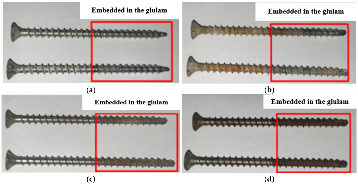
A comparison of STSs after withdrawal test in aged specimens (Figure 10) reveals that the severity of rusting increases with the number of aging cycles. Both external and embedded portions of the screws were examined. The exposed portions of the screws in Group A-6 exhibited more pronounced rusting than those in Group B-6 (Figure 10b,d). This difference is attributed to an additional step in Method A, which involves exposure to water vapor. This exposure accelerates oxidation on the metal surfaces exposed to the external environment. In contrast, the embedded portions of the screws within the glulam showed more severe rusting in Group B-3 and B-6 (Figure 10c,d), suggesting that the improved protocol (Method B) may intensify corrosion at the embedded interface. This observation confirms that corrosion of the steel components, as hypothesized in the abstract, was indeed observed experimentally and contributed to the overall degradation of connection performance.
The cross-sectional image of the screw thread impressions in the glulam is presented in Figure 11. As the number of aging cycles increased, the color of the thread impressions on the timber surface darkened. This corresponds with the increasing severity of screw rusting observed in Figure 10, indicating chemical interaction between corroded screw surfaces and the surrounding wood. The thread indentations in specimens subjected to Method B were similar in color to those in Method A. In the B-3 group, the darkened tip area resulted from the STS intersecting with a wood knot. This caused intense friction and localized surface charring due to high temperatures during drilling (Figure 11d). This localized effect was noted as an isolated anomaly rather than a systematic aging-related phenomenon.

3.1.4. Load–Displacement Curves of Glulam Specimens

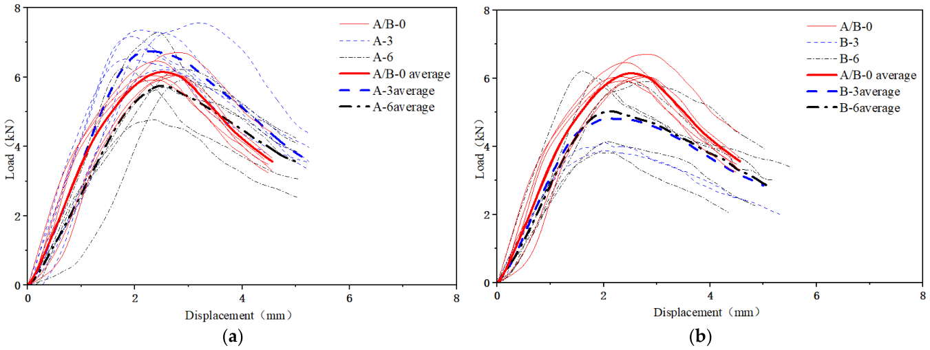
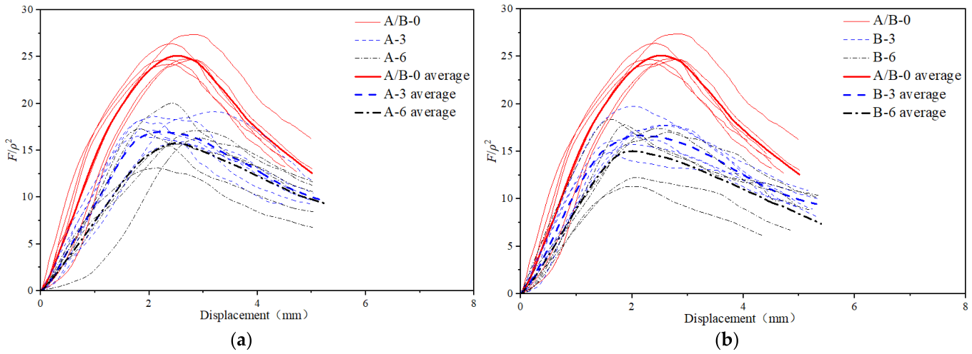
The load–displacement curves for the withdrawal tests of the glulam specimens are shown in Figure 12. As the number of aging cycles increased, both aging groups exhibited irregularities in the peak load and slope of the curves. Due to significant variability in wood density among the specimens in each group (Table 3), a direct comparison of their test curves is not appropriate. According to German and Canadian standards [33,34], the withdrawal capacity of STSs is proportional to the square of the wood density (ρ2). This relationship is expressed in Equations (3) and (4). In this section, the withdrawal curves of the specimens are normalized to eliminate the effect of density. This normalization reduces the impact of wood density variation on the results. The normalized parameter used to assess withdrawal performance is the ratio of loading force (F) to ρ2 (F/ρ2). The F /ρ2-displacement curve is shown in Figure 13.
During the initial loading phase, while the specimen remains in the elastic phase, the load increases linearly with displacement. As displacement increases, the slope of the curve decreases gradually. This indicates that the specimen has entered the yielding phase, during which the STS begins to be withdrawn. In the descending phase, the specimen exhibits a degree of ductility as the screw is withdrawn. As the number of aging cycles increases, both the ascending and descending segments of the curve become progressively flatter.
R ax , k = φ 10 6 ρ k 2 d l ef sin 2 α + 4 3 cos 2 α
P ax , k = φ 0.8 δ ( b 0.4 ρ ) 2 d l ef 10 6 sin 2 α + 4 3 cos 2 α K D K SF
where Rax,k and Pax,k are the withdrawal bearing capacity; ρk and ρ represent the characteristic and oven-dry wood densities, respectively; d is the nominal diameter of the self-tapping screw; lef is the effective embedment depth of the screw; α is the angle between the screw axis and the wood grain; φ is the value based on the tensile load capacity of the screw; b varies for different board materials; KD is the loading duration factor; KSF is the service condition factor and δ is the material adjustment factor.

3.1.5. Analysis of Withdrawal Capacity and Stiffness

The slope of the load-slip curves from 1.3 kN to 2.7 kN, within the generally linear range, is adopted to represent the stiffness of the specimens [40]. Based on the formulas for withdrawal capacity specified in international standards, which are introduced in Equations (1) and (2), the test results for withdrawal capacity (P1), stiffness (K1) and corresponding normalized parameters (P1/ρ2 and K1/ρ2) are listed in Table 6.
After aging, the retention rate of normalized withdrawal capacity (c1) for method B was lower than that for method A. The relative error of withdrawal capacity retention rates for three and six aging cycles between method A and B is 2.38% and 2.92%, respectively. Conversely, the retention rate (c2) of normalized stiffness for method B was larger than that for method A. After three and six aging cycles, the relative error of stiffness retention rates between method A and B is 5.77% and 9.21%, respectively. The retention rates for withdrawal capacity and stiffness were comparable under both aging methods. Therefore, method B can be considered an equivalent alternative to method A for aging tests of the glulam anchorage specimens.
The coefficients of variation, 95% confidence intervals, and RSE values were used together to evaluate the variability and relative precision of the glulam withdrawal test results. Although the coefficients of variation indicate noticeable scatter among individual specimens, the RSE values of the main withdrawal parameters were below 10%, indicating that the estimated mean values had acceptable relative precision for comparative analysis. The observed scatter is mainly attributed to the natural heterogeneity of wood. Local density differences can directly affect the bearing and friction resistance around the screw thread. Grain orientation may also influence the direction of crack propagation during screw withdrawal. In addition, knots and local defects can change the stress distribution near the screw embedment zone. Small deviations during pre-drilling and screw installation may further increase the scatter of the results. Thus, the variability observed in the glulam tests was considered to result from the combined effects of material heterogeneity and specimen preparation, while the RSE results indicate that the group mean values remained sufficiently precise for evaluating the effects of aging methods and aging cycles.
Overall, Method B showed comparable aging effects to Method A in the glulam withdrawal tests. The two methods produced similar macroscopic cracking characteristics and comparable density reductions. The density retention rates of two ageing methods differed by less than 3% after each group of aging cycles. Both of the failure modes were screw pull-out. This indicates that Method B did not change the withdrawal failure mechanism. The retention rates of normalized withdrawal capacity and stiffness were also close. Consequently, Method B can be considered comparable to Method A for the main aging mechanisms related to STS withdrawal behavior. Based on this verification, Method B was used in the subsequent CLT aging tests.
This comparison should be regarded as a preliminary validation of the aging method. It does not mean that glulam can fully represent CLT. Therefore, the improved aging method was further applied to CLT specimens in Section 3.

3.2. Withdrawal Performance of STSs in CLT After Accelerated Aging

3.2.1. Aging Characterization

The macroscopic characteristics and mechanisms of the aged CLT withdrawal specimens are similar to those of aged glulam (Figure 14). Each layer of the CLT specimen exhibited deformation due to dimensional and volumetric changes. These changes were caused by hygroscopic shrinkage and swelling. Cracking after aging was classified into two types: glue layer cracking and shrinkage cracking. The macroscopic features of the aged CLT withdrawal specimens included both deformation and cracking. The dimensional changes in the CLT before and after the aging cycles, as well as the maximum crack widths of the specimens, are shown in Table 7 and Table 8. The data demonstrate that as the number of aging cycles increased, both the deformation trends and crack widths became progressively larger. This phenomenon aligns with the aging behavior observed in glulam. A comparison of the aging phenomena in both glulam and CLT reveals that factors such as wood shrinkage, temperature and humidity changes, and adhesive durability persist throughout the aging process. These factors collectively influence the aging process and characteristics of CLT.
Such variations cover deformation, crack width, density variation, and pull-out mechanical behavior. Swelling and shrinkage characteristics were inferred from size variation and crack propagation. Glue joint damage was determined through visual observation and maximum crack dimension measurement. The obtained results mainly reflect the macroscopic aging deterioration of the test samples, yet fail to directly reveal the rules of moisture migration, the attenuation of bonding strength, and the crack-expansion process. Subsequent research will introduce humidity monitoring, bonding property tests, and quantitative delamination detection for further analysis.

3.2.2. Density of CLT Specimens

The density of wood in each layer of CLT may vary. Material density is a critical factor influencing the withdrawal resistance of STSs [37,38]. To eliminate the potential effect of density variation on the anchorage test results, samples were collected from the first and second layers of the CLT specimens, as these are the layers that the STSs penetrate. Samples were gathered both before and after aging. Clear specimens with the dimension of 20 mm × 20 mm × 20 mm were prepared to measure the oven-dry density [39], as shown in Table 9.
A comparison of densities in the CLT withdrawal test specimens before and after aging was conducted. The density retention rates for Group B-3 and B-3 after three and six aging cycles were 89.05% and 87.38%, respectively. The density retention rates were similar, indicating that different aging cycles had a relatively mild effect and high reliability on the CLT density. However, the density retention rate of CLT after aging was lower than that of glulam, likely due to its distinct structural characteristics. Overall, density differences did not significantly influence the anchorage test results.

3.2.3. Failure Mode of CLT Withdrawal Specimens

During the initial loading stage, the CLT exhibited behavior similar to glulam, remaining in the linear elastic phase. After aging, the occurrence of the fiber tearing sound was observed earlier. The specimens in the unaged group, three-aging-cycle group, and six-aging-cycle group began emitting continuous fiber fracture sounds at 60–65%, 40–45%, and 20–30% of the maximum load, respectively. This demonstrates a clear downward trend in the damage initiation threshold with increasing aging cycles. As the load reached 80–85% of the maximum, the intensity of the fiber fracture sounds increased progressively until the peak load was reached. The test was terminated when the load dropped below 70% of the maximum load. All specimens exhibited the same failure mode, characterized by the pull-out of the STSs. The post-peak response showed a gradual load decay and indicated that the connection maintains a degree of safety margin after peak load.
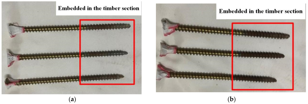
As the number of aging cycles increased, the self-tapping screws exhibited progressive rusting. The screws exposed to the outside environment showed no significant rusting, as they were not affected by steam. The portion of the screws embedded in the timber developed a relatively uniform rust color, as illustrated in Figure 15. This differential rusting pattern suggests that the timber environment itself contributes to corrosion, likely due to the acidic nature of wood or the presence of moisture within the timber matrix during aging.
It should be recognized that the corrosion of STSs was evaluated only by visual observation in this study. No quantitative corrosion index, such as mass loss, surface roughness, or microscopic morphology, was measured. The corrosion results were used as qualitative evidence of changes at the screw–wood interface after aging. Future studies should include measurements of mass loss and surface characterization to clarify the quantitative relationship between screw corrosion and withdrawal behavior.
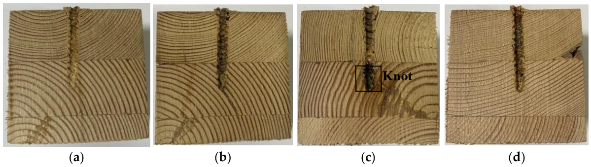
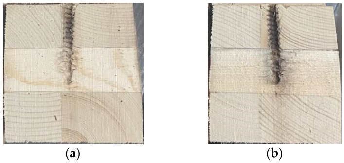
The cross-sectional image of the screw thread impressions in CLT is presented in Figure 16. As the number of aging cycles increased, the color of the thread impressions on the wood surface deepened. This deepening correlated consistently with the increasing severity of screw rusting observed in Figure 15, further confirming the chemical interaction between corroded screw surfaces and the adjacent wood substrate.

3.2.4. Load–Displacement Curves of CLT Specimens

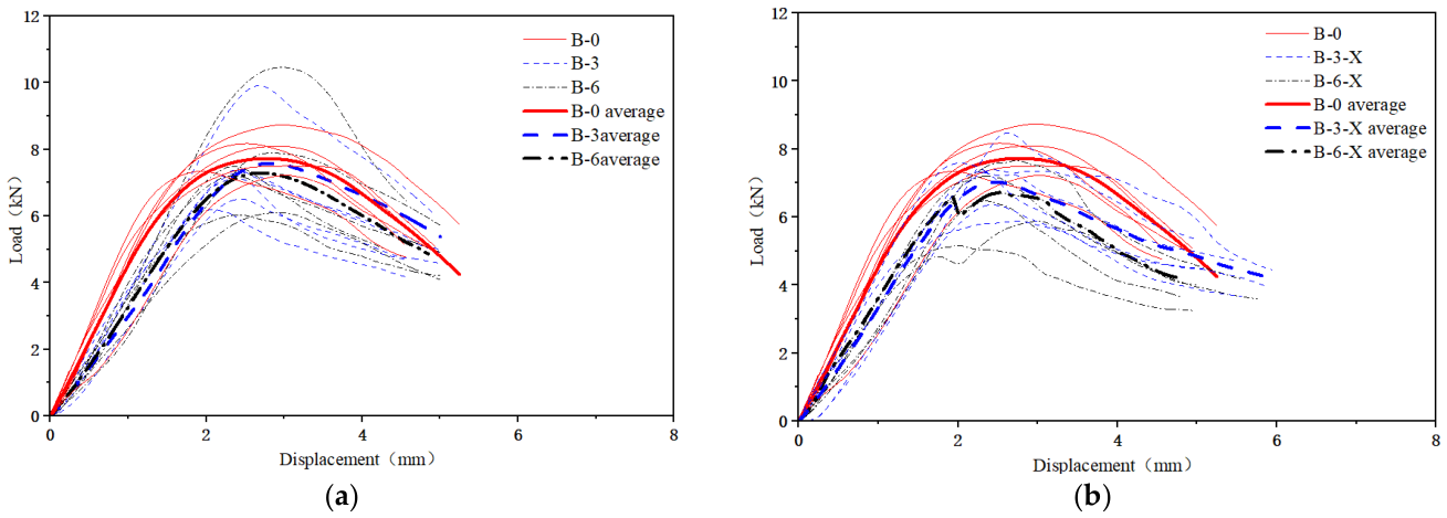
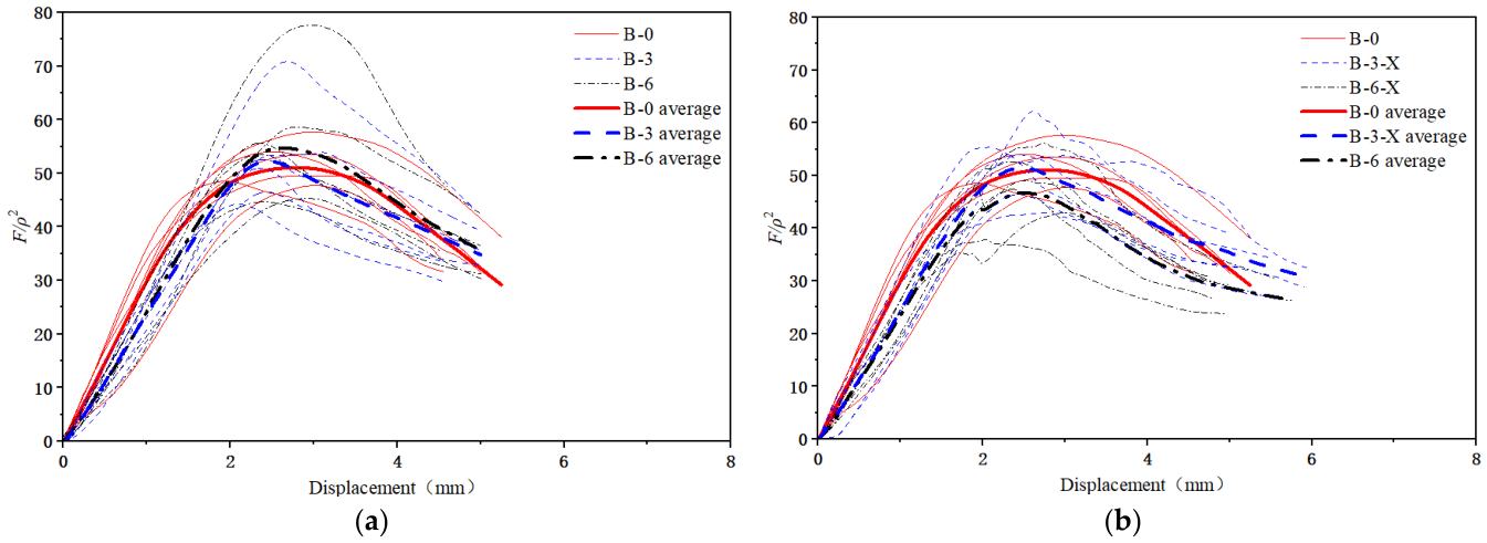
The load–displacement curves for the withdrawal tests of the CLT specimens are shown in Figure 17. The load–displacement curves were normalized using F/ρ2 to reduce the influence of density variation. It was based on the empirical relationship between screw withdrawal resistance and wood density in previous standards and studies [28,37,38]. Since there are differences between layers, adhesive interfaces, and fiber orientations, this normalization should be regarded as a preliminary correction method. It cannot fully describe the withdrawal mechanism of STSs in CLT. The distance from the screw to the vertical adhesive layer significantly affects the withdrawal performance of STSs in CLT. Groups B-3 and B-6 did not account for the distance and their curves showed no clear pattern in relation to the aging cycles (Figure 17a). Then B-0 and the groups with the same distance from the screw to the adhesive layer (B-3-X, B-6-X) were compared (Figure 17b). The load–displacement curves of the CLT specimens denoted undergoing elastic and plastic phases similar to that of glulam. As the number of aging cycles increased, the upward slope of the curve progressively decreased.
This section normalizes the load–displacement curves of the specimens to eliminate the effect of density variation (Figure 18). This normalization is based on the CLT density measurement results (Table 9). After removing the effects of density, the curves of Groups B-3 and B-6 show no significant change, while those of Groups B-3-X and B-6-X exhibit a more pronounced relationship with the number of aging cycles. Therefore, the distance from the screw to the adhesive layer has a greater influence on the withdrawal behavior of self-tapping screws in aged CLT than the density.
The curves of two groups of specimens with the same distance from the screw to the adhesive layer (Figure 18b) reveal a consistent trend. During the initial loading stage, the load–displacement curves rise linearly and rapidly. As displacement increases, the slope of the curves decreases gradually. After reaching the maximum load, the curves progressively decline. Compared to the unaged specimens, the aged specimens had a lower ultimate load for screw withdrawal as the number of aging cycles increased. Additionally, both the upward and downward trends of the load–displacement curve became slower.

3.2.5. Withdrawal Resistance and Stiffness

The withdrawal resistance results of the test specimens are shown in Table 10, including the withdrawal capacity (P2), stiffness (K2) and corresponding normalized parameters (P2/ρ2 and K2/ρ2). The slope of the load-slip curves from 2 kN to 4 kN, within the generally linear range, is adopted to represent the stiffness of the specimens (K2) [39,40]. After aging, the retention rates of normalized withdrawal capacity and stiffness relative to their values before aging are denoted as c3 and c4, respectively (Table 10).
The F/ρ2 normalization could reduce the influence of density differences to a certain degree. Since CLT is layered and heterogeneous, the response around the screw may also depend on the direction of each layer, the position of the glue line, and how stress is transferred between adjacent lamellas. Thus, P2/ρ2 and K2/ρ2 were used only for comparison after density correction. They should not be regarded as parameters that fully remove the effects of CLT structure.
In this study, the normalized parameters were used as comparative indicators. They were mainly used to reduce the primary influence of density. The CLT-specific effects were further discussed by comparing specimens with different STVGD. The results showed that the screw position relative to the vertical glue line affected the aged withdrawal behavior. This implies that local structural characteristics should be considered together with density-normalized parameters when evaluating STS withdrawal performance in CLT.
Compared to the indistinguishable pattern of the withdrawal resistance in groups B-3 and B-6, that in the groups B-3-X and B-6-X with the same distance from the screw to the adhesive layer gradually decreases with increasing number of aging cycles. And the test results of the later groups demonstrate reduced variability. It is noted that the average withdrawal resistance of the STSs in groups B-3 and B-6 also demonstrates a gradual decrease with increasing number of aging cycles after excluding the influence of material density. As demonstrated by the load–displacement curves (17b), the density variation has a significant effect on the withdrawal resistance of STSs. The analysis of the load-bearing capacity for the specimens ignoring the distance from the vertical glue layer after aging should correct for this density effect. With prolonged aging time, the specimens without maintained distance will exhibit lower load-bearing capacity than those with maintained distance. By the sixth aging cycle, the former shows a reduction of approximately 5% compared to the latter. Ensuring adequate distance from the vertical glue layer may lead to greater long-term resilience and withdrawal capacity.
From a design perspective, the distance between the screw and the vertical glue line should not be overlooked. Eurocode 5 and similar timber design rules mainly give requirements for screw spacing, end distance, and edge distance. These distances are measured from member edges, loaded ends, or nearby fasteners. They do not directly consider the vertical glue line inside CLT.
The present results show that vertical glue lines may become preferential cracking paths after aging. Therefore, the screw position relative to the vertical glue line should be considered in the design and testing of STS connections in CLT. In practical applications, screws should be arranged away from visible or potential glue-line cracks when possible. In experimental studies, the STVGD should also be reported and controlled. However, only limited distances were considered in this study and the universal minimum distance cannot be proposed at this stage.
After three and six aging cycles, the normalized withdrawal capacity retention rates were 104.98% and 95.36%, respectively. The normalized stiffness retention rates were 85.60% and 80.94%, respectively. The aging cycles had a greater effect on the withdrawal stiffness of STSs in CLT than on their withdrawal capacity, especially during the first three cycles. As the number of aging cycles increased, the trends in withdrawal capacity and stiffness retention rates became similar to those observed in glulam.
It should be interpreted with caution that the normalized withdrawal capacity retention rate exceeded 100% in the three-cycle aged groups. It does not necessarily indicate an improvement in the intrinsic withdrawal resistance of aged CLT. Several factors may have contributed to this phenomenon, such as densification effects, moisture redistribution, or increased friction due to surface changes. First, the cracking of vertical glue lines after aging may have affected the accuracy of local density measurement. Second, repeated wetting and drying may have caused local densification around the screw thread. Third, moisture redistribution may have changed the local contact condition at the screw–wood interface. In addition, slight surface roughening and corrosion of the embedded screw may have increased the friction resistance during withdrawal. These effects may temporarily offset part of the degradation caused by aging.
For the CLT specimens, the coefficients of variation, 95% confidence intervals, and RSE values were used together to evaluate the variability and relative precision of the withdrawal test results. The confidence intervals of withdrawal capacity in the aged groups were generally larger than those of the unaged group, indicating increased scatter among individual specimens after aging. However, the RSE values of P2 and K2 were all below 10%, suggesting that the estimated group mean values still had acceptable relative precision for comparative analysis. The observed variability may be related to both the natural heterogeneity of wood and the layered structure of CLT. Different lamellas may have different densities, grain orientations, and local defects, which can lead to nonuniform stress transfer around the screw. In addition, vertical glue lines and edge-glued interfaces may become preferential cracking paths after aging. The STVGD may therefore affect withdrawal behavior and data scatter. Small deviations in pre-drilling or screw installation may also contribute to the variability. Therefore, although scatter existed among individual specimens, the RSE results indicate that the group mean values were sufficiently precise for evaluating the effects of aging cycles and STVGD.
The results with only three and six aging cycles should be interpreted as performance changes resulting from aging, using the improved accelerated aging method. They should not be directly converted into long-term service-life predictions. Furthermore, accelerated aging cannot fully reproduce all factors in real service environments. These factors may include long-term moisture fluctuation, biological degradation, load duration, and repeated mechanical loading. Therefore, further studies with more aging cycles, natural exposure tests, and long-term monitoring are needed.

4. Discussion

The comparison between Method A and Method B provides a basis for using the improved accelerated aging method in the subsequent CLT tests. Although Method B omits the freeze–thaw stage, it retains repeated hot-water soaking and high-temperature drying. These processes can induce moisture gradients, swelling–shrinkage deformation, internal stress development, and screw–wood interface degradation. These mechanisms are closely related to the withdrawal behavior of STSs. Thus, Method B can be considered suitable for the rapid evaluation of STS withdrawal specimens under the conditions of this study. However, its applicability to other service environments still needs further verification.
The results of the CLT tests show that the aging effect on STS withdrawal behavior is not governed only by material density. CLT has a layered structure, orthogonal lamellas, and internal glue lines. These features may change stress transfer around the screw. They may also provide preferential paths for crack development after aging. Therefore, the local structural characteristics of CLT should be considered together with density-normalized parameters when interpreting withdrawal performance. Future studies should combine experimental results with finite element analysis. This would help clarify the local stress transfer, damage evolution, and withdrawal mechanism of STSs in aged CLT.
The STVGD is important for both experimental design and practical application. Current timber design provisions, such as Eurocode 5, mainly specify screw spacing, end distance, and edge distance. However, the internal vertical glue line in CLT is not explicitly considered. The present results suggest that this distance should be reported and controlled in future tests. In practical applications, screws should be arranged away from visible or potential glue-line cracks when possible. However, a universal minimum distance cannot be proposed at this stage because only limited distances were investigated.
Several limitations should also be noted. Only three and six aging cycles were considered; the conclusions should be limited to the improved accelerated aging method used in this study. The results cannot be directly used to predict the full service life of CLT connections. Future research should include more aging cycles, natural exposure conditions, and long-term monitoring to verify the durability of STS connections in CLT. In addition, the tests were not continued until full screw withdrawal. Future studies should extend the loading process to full screw withdrawal. This would help evaluate post-peak behavior, ductility, and energy dissipation more completely. Screw corrosion was evaluated only by visual observation. Future tests should continue loading until the screw is fully withdrawn. This would enable analysis of the post-peak response, ductility, and energy dissipation in greater detail. In the present study, screw corrosion was assessed only by visual inspection. Later work should add direct measurements, such as mass loss, surface roughness, and microscopic morphology. These data would help explain how corrosion affects the screw–wood interface and withdrawal resistance. Moisture change, adhesive bond degradation, and delamination should also be measured more directly, because they are important for understanding the aging mechanism of STS connections in CLT.

5. Conclusions

A comprehensive experimental analysis was conducted on the withdrawal resistance of STSs in both glued laminated timber and CLT. The analysis of the effects of different aging schemes and the number of cycles on the failure modes, withdrawal capacity, and stiffness of the specimens led to the following conclusions. It should be noted that these conclusions are limited to the materials, specimen dimensions, screw parameters, and aging cycles used in this study.
(1)
The withdrawal test results of glulam specimens were compared between method A and method B. The relative error of withdrawal capacity retention rates for three and six aging cycles between method A and B is 2.38% and 2.92%, respectively. The results indicated that the effects were similar for both methods. This confirms the feasibility of method B for investigating the withdrawal resistance of self-tapping screws in CLT after aging.
(2)
After aging treatment, the failure mode of CLT with STSs was all pull-out of self-tapping screws. As the number of aging cycles increased, the incidence of wood fiber tearing became more pronounced. A decrease in the ratio of the counterpart load to the ultimate load was observed. After three and six aging cycles, the normalized withdrawal capacity retention rates were 104.98% and 95.36%, respectively, and the normalized stiffness retention rates were 85.60% and 80.94%, respectively. The measurement uncertainty, local material changes, and screw–wood interface changes may lead to the retention rate exceeding 100% after three aging cycles. This differential response indicates that stiffness is significantly more sensitive to environmental aging than withdrawal capacity.
(3)
Cracking of the vertical glue layer significantly influenced the withdrawal performance of STSs in CLT specimens. In the comparative experiment, two groups of specimens, with the same distance from the screw to the adhesive layer, exhibited consistent changes. This suggests that experimental designs may benefit from accounting for density effects and maintaining a consistent distance from the screw to the adhesive layer. In addition, when the screw is positioned closer to the vertical adhesive layer, aging-induced cracking or delamination tends to occur along the glue line, weakening the surrounding wood and reducing the long-term anchorage effectiveness of the screw. To facilitate practical implementation, this finding may be worth considering in relation to existing spacing requirements for STSs in CLT. Current timber design provisions, such as Eurocode 5, mainly specify screw spacing, end distance, and edge distance, but the distance between the screw and the internal vertical glue layer in CLT is not explicitly considered. The current study indicates that such a distance criterion is warranted and should be considered for integration into future code revisions. Further tests are still needed to establish a quantitative minimum design distance.
This study provides a reference for understanding the anchorage performance of STSs in CLT after aging. However, given that only six aging cycles were performed, caution should be exercised when extrapolating these results directly to long-term service performance. The present study did not directly measure moisture content evolution, adhesive bond degradation, quantitative delamination, or screw corrosion mass loss. Future research will investigate the connection performance of CLT joints with STSs under various aging environments. It will also aim to optimize aging protocols to improve practical applications, such as enhancing structural durability and safety. More aging cycles, natural exposure tests, and quantitative measurements of moisture variation, adhesive performance, delamination, and screw corrosion should also be considered in future work. In addition, numerical modeling of aged CLT joints will be conducted in future work to further clarify the evolution of stress distribution and failure mechanisms under cyclic environmental conditions.

Author Contributions

Conceptualization, H.L. and Y.Z.; Methodology, H.L., J.Z. and P.W.; Investigation, H.L.; Resources, Z.W. and Y.Z.; Data curation, Z.G., J.Z. and P.W.; Writing—original draft, H.L., Z.G. and P.W.; Writing—review & editing, H.L., Z.G. and P.W.; Visualization, Z.G. and J.Z.; Supervision, Z.W. and Y.Z.; Funding acquisition, H.L. All authors have read and agreed to the published version of the manuscript.

Funding

This research was funded by the National Natural Science Foundation of China, grant number 51908291, and the Technology Innovation Fund Project of Nanjing Forestry University, “Mechanical Properties and Design Method of Self-tapping Screw Reinforced Wood Beam Joint”, grant number CX2019002.

Data Availability Statement

The data presented in this study are available on request from the corresponding author. (the data are not publicly available due to privacy.)

Conflicts of Interest

The authors declare no conflict of interest.

References

  1. Yusoh, A.S.; Tahir, P.M. Effect of wood species, clamping pressure and glue spread rate on the bonding properties of cross-laminated timber (CLT) manufactured from tropical hardwoods. Constr. Build. Mater. 2021, 273, 121721. [Google Scholar] [CrossRef] [Scilit]
  2. Younis, A.; Dodoo, A. Cross-laminated timber for building construction: A life-cycle-assessment overview. J. Build. Eng. 2022, 52, 104482. [Google Scholar] [CrossRef] [Scilit]
  3. Ilgin, H.E.; Karjalainen, M.; Mikkola, P. Views of Cross-Laminated timber (CLT) manufacturer representatives around the world on CLT practices and its future outlook. Buildings 2023, 13, 2912. [Google Scholar] [CrossRef] [Scilit]
  4. Udele, K.E.; Morrell, J.J.; Sinha, A. Biological durability of cross-laminated timber—The state of things. For. Prod. J. 2021, 71, 124–132. [Google Scholar] [CrossRef] [Scilit]
  5. Liu, W.; Yang, H. Research progress on modern timber structures. J. Build. Struct. 2019, 40, 16–43. (In Chinese) [Google Scholar]
  6. Izzi, M.; Casagrande, D. Seismic behaviour of Cross-Laminated Timber structures: A state-of-the-art review. Eng. Struct. 2018, 170, 42–52. [Google Scholar] [CrossRef] [Scilit]
  7. Fitzgerald, D. Axial slip-friction connections for cross-laminated timber. Eng. Struct. 2021, 228, 111478. [Google Scholar] [CrossRef] [Scilit]
  8. Silva, C.; Branco, J.M.; Mehdipour, Z. Strain variation analysis of cross-laminated timber elements under cyclic moisture. J. Build. Eng. 2021, 41, 102373. [Google Scholar] [CrossRef] [Scilit]
  9. Zheng, X.; He, M.; Li, Z.; Luo, Q. Long-term performance of post-tensioned cross-laminated timber (CLT) shear walls: Hygro-mechanical model validation and parametric analysis. Arch. Civ. Mech. Eng. 2022, 22, 68. [Google Scholar] [CrossRef] [Scilit]
  10. Lima, D.F.; Duarte, S.; Branco, J.M.; Nunes, L. Mass Timber Buildings: The associated risks of rainwater exposure during construction in the Portuguese climate. J. Build. Eng. 2024, 98, 111110. [Google Scholar] [CrossRef] [Scilit]
  11. Morrell, I.; Udele, K.E.; Morrell, J.J.; Sinha, A. Effect of Biodeterioration on Modeling Parameters of Code-Compliant Cross-Laminated Timber Lateral Connections. For. Prod. J. 2024, 74, 130–142. [Google Scholar] [CrossRef] [Scilit]
  12. Ayanleye, S. Durability and protection of mass timber structures: A review. J. Build. Eng. 2022, 46, 103731. [Google Scholar] [CrossRef] [Scilit]
  13. Shi, X.; Yue, K.; Jiao, X. Experimental investigation into lateral performance of cross-laminated timber shear walls made from fast-growing poplar wood. Wood Mater. Sci. Eng. 2023, 18, 1212–1227. [Google Scholar] [CrossRef] [Scilit]
  14. Silva, C.; Branco, J.M. The influences of moisture content variation, number and width of gaps on the withdrawal resistance of self tapping screws inserted in cross laminated timber. Constr. Build. Mater. 2016, 125, 1205–1215. [Google Scholar] [CrossRef] [Scilit]
  15. Toumpanaki, E.; Gawne, A.; Humphreys, R.; Vojnovic, L. Effect of moisture and rate of loading in the withdrawal capacity of screws in Cross Laminated Timber (CLT). Structures 2024, 69, 107530. [Google Scholar] [CrossRef] [Scilit]
  16. Tran, D.K.; Jeong, G.Y. Withdrawal capacity and strength of self-tapping screws on cross-laminated timber. Structures 2022, 37, 772–786. [Google Scholar]
  17. Lee, I.H.; Lee, S.M.; Kim, K.H. Improved design of self-tapping screw (STS) for Korean larch and red pine cross laminated timber (CLT). BioResources 2024, 19, 3353–3361. [Google Scholar] [CrossRef] [Scilit]
  18. Udele, K.E.; Morrell, J.J.; Cappellazzi, J.; Sinha, A. Characterizing properties of fungal-decayed cross laminated timber (CLT) connection assemblies. Constr. Build. Mater. 2023, 409, 134080. [Google Scholar] [CrossRef] [Scilit]
  19. Udele, K.E.; Morrell, I.; Morrell, J.J.; Sinha, A. Biological durability of cross laminated timber connections. Data Brief 2024, 55, 110698. [Google Scholar] [CrossRef] [Scilit]
  20. BS EN 1087-1:1995; Particleboards—Determination of Moisture Resistance—Part 1: Boil Test. British Standards Institution: London, UK, 1995.
  21. EN 927-6:2018; Paints and Varnishes—Coating Materials and Coating Systems for Exterior Wood—Part 6: Exposure of Wood Coatings to Artificial Weathering Using Fluorescent UV Lamps and Water. European Committee for Standardization: Brussels, Belgium, 2018.
  22. ASTM D1037; Standard Test Methods for Evaluating Properties of Wood-Base Fiber and Particle Panel Materials. ASTM International: West Consecutive Hawke, PA, USA, 2012.
  23. Kojima, Y.; Suzuki, S. Evaluating the durability of wood-based panels using internal bond strength results from accelerated aging treatments. J. Wood Sci. 2011, 57, 7–13. [Google Scholar] [CrossRef] [Scilit]
  24. Wang, R. Mechanical properties of aged glue laminated bamboo for structural members. Ind. Crops Prod. 2024, 209, 118017. [Google Scholar] [CrossRef] [Scilit]
  25. Petrillo, M.; Sandak, J.; Grossi, P.; Sandak, A. Chemical and appearance changes of wood due to artificial weathering–dose–response model. J. Near Infrared Spectrosc. 2019, 27, 26–37. [Google Scholar] [CrossRef] [Scilit]
  26. EN 1995-1-1: 2004+A1: 2008; Design of Timber Structures-Part 1-1: General-Common Rules and Rules for Buildings. European Committee for Standardization: Brussels, Belgium, 2004.
  27. Gao, Y.W. The Degeneration on Mechanical Properties of Aged Woodand Corresponding Damage Constitutive Model. Master’s Thesis, Yangzhou University, Yangzhou, China, 2016. (In Chinese) [Google Scholar]
  28. Ringhofer, A.; Brandner, R.; Schickhofer, G. Withdrawal resistance of self-tapping screws in unidirectional and orthogonal layered timber products. Mater. Struct. 2015, 48, 1435–1447. [Google Scholar] [CrossRef] [Scilit]
  29. Liu, Y.; Yao, Z.; Wang, F.; Huang, H.; Que, Z. Effect of arrangement distances on stiffness of shear-tension mode in timber-to-timber connections with inclined screws. Constr. Build. Mater. 2022, 314, 125592. [Google Scholar] [CrossRef] [Scilit]
  30. Abdoli, F.; Rashidi, M.; Rostampour-Haftkhani, A.; Layeghi, M.; Ebrahimi, G. Effects of fastener type, end distance, layer arrangement, and panel strength direction on lateral resistance of single shear lap joints in cross-laminated timber (CLT). Case Stud. Constr. Mater. 2023, 18, e01727. [Google Scholar] [CrossRef] [Scilit]
  31. McNatt, J.D.; Link, C.L. Analysis of ASTM D1037 accelerated-aging test. For. Prod. J. 1989, 39, 51–57. [Google Scholar]
  32. GB/T 1927.5-2021; Test Methods for Physical and Mechanical Properties of Small Clear Wood Specimens—Part 5: Determination of Density. China Standards Press: Beijing, China, 2021. (In Chinese)
  33. Brandner, R.; Flatscher, G.; Ringhofer, A. Cross laminated timber (CLT): Overview and development. Eur. J. Wood Wood Prod. 2016, 74, 331–351. [Google Scholar] [CrossRef] [Scilit]
  34. Shanghai Moregood Hardware Co., Ltd. Moregood Connection System Technical Handbook; Shanghai Moregood Hardware Co., Ltd.: Shanghai, China, 2019. [Google Scholar]
  35. LY/T 3219-2020; Self-Tapping Screws for Timber Structures. China Standards Press: Beijing, China, 2020. (In Chinese)
  36. Lee, D.K.; In, J.; Lee, S. Standard deviation and standard error of the mean. Korean J. Anesthesiol. 2015, 68, 220–223. [Google Scholar] [CrossRef] [Scilit]
  37. DIN 1052:2010; Design Calculation and Dimensioning of Timber Structures—General Rules and Rules for Building Construction. Deutsches Institut für Normung: Berlin, Germany, 2010.
  38. CCMC. Evaluation Report CCMC 13677-R: SWG ASSY and VG Plus and SWG ASSY 3.0 Self-Tapping Wood Screws; Canadian Construction Material Center: Ottawa, ON, Canada, 2013. [Google Scholar]
  39. EN 26891:1991; Timber Structures-Joints Made with Mechanical Fasteners-General Principles for the Determination of Strength and Deformation Characteristics. British Standards Institution: London, UK, 1991.
  40. Li, H.; Qiu, H.; Wang, Z.; Lu, Y. Withdrawal resistance of the self-tapping screws in engineered bamboo scrimber. Constr. Build. Mater. 2021, 311, 125315. [Google Scholar] [CrossRef] [Scilit]
Figure 1. CLT.
Figure 1. CLT.
Buildings 16 02208 g001
Figure 2. The end-grain face of CLT after repeated wetting and drying [10].
Buildings 16 02208 g002
Figure 3. Flowchart of the experimental program for evaluating the withdrawal behavior of STSs after accelerated aging.
Buildings 16 02208 g003
Figure 4. The cyclical steps and corresponding equipment of the ASTM D1037 aging method and the improved ASTM D1037 aging method: (a) ASTM D1037 aging method (Scheme A); (b) Improved ASTM D1037 aging method (Scheme B).
Buildings 16 02208 g004
Figure 5. Schematic diagram of the withdrawal test specimen for laminated wood: (a) Side view; (b) Top view; (c) Perspective view.
Buildings 16 02208 g005
Figure 6. Schematic diagram of the experiment and experimental setup: (a) Schematic diagram of the experiment setup; (b) Diagram of the experiment setup.
Buildings 16 02208 g006
Figure 7. Schematic diagram of complementary groups with consistent vertical glue layer positions.
Buildings 16 02208 g007
Figure 8. Schematic diagram of CLT withdrawal specimen: (a) Top view and side view; (b) Perspective view.
Buildings 16 02208 g008
Figure 9. Cracking after aging for glulam: (a) A-3; (b) A-6; (c) B-3; (d) B-6.
Buildings 16 02208 g009aBuildings 16 02208 g009b
Figure 10. Screws after withdrawal test in glulam: (a) A-3; (b) A-6; (c) B-3; (d) B-6.
Buildings 16 02208 g010
Figure 11. Interface between glulam and screw: (a) A-3; (b) A-6; (c) B-3; (d) B-6.
Buildings 16 02208 g011
Figure 12. Load–displacement curve of the test specimen: (a) A-3 and A-6; (b) B-3 and B-6.
Buildings 16 02208 g012
Figure 13. Load normalized parameter-displacement curve: (a) A-3 and A-6; (b) B-3 and B-6.
Buildings 16 02208 g013
Figure 14. Cracking after aging: (a) B-3; (b) B-6.
Buildings 16 02208 g014
Figure 15. Rusting after aging: (a) B-3; (b) B-6.
Buildings 16 02208 g015
Figure 16. Interface between CLT and screw: (a) B-3; (b) B-6.
Buildings 16 02208 g016
Figure 17. Load–displacement curve of the test specimen: (a) B-3 and B-6; (b) B-3-X and B-6-X.
Buildings 16 02208 g017
Figure 18. Specimen withdrawal capacity normalized parameter-displacement curves: (a) B-3 and B-6; (b) B-3-X and B-6-X.
Buildings 16 02208 g018
Table 1. Mechanical parameters of self-tapping screws used in the glulam withdrawal tests.
Diameter d
(mm)
Length l
(mm)
Minimum Breaking Torque
(N·m)
Tensile Strength
(MPa)
Yielding Strength
(MPa)
Shearing Strength
(MPa)
61001.5500300300
Table 2. Parameters of glulam withdrawal specimens in each group.
Specimen Groupa × b × h (mm)lp (mm)Aging ProgramNumber of CyclesNumber of Specimens
A/B-080 × 80 × 1254806
A-380 × 80 × 12548A36
A-680 × 80 × 12548A66
B-380 × 80 × 12548B36
B-680 × 80 × 12548B66
Note: a × b × h represents the length, width, and height of the specimen; “lp” refers to the embedding depth of the self-tapping screw.
Table 3. Mechanical parameters of self-tapping screws used in the CLT withdrawal tests.
Diameter d
(mm)
Length l
(mm)
Minimum Breaking Torque
(N·m)
Tensile Strength
(MPa)
Yielding Strength
(MPa)
Shearing Strength
(MPa)
81602.8600400400
Table 4. Parameters of CLT withdrawal specimens in each group.
Specimen Groupa × b × h (mm)lp (mm)lc (mm)Aging ProgramNumber of CyclesNumber of Specimens
B-0105 × 105 × 1806415/06
B-3105 × 105 × 1806425B36
B-6105 × 105 × 1806425B66
B-3-X105 × 105 × 1806415B36
B-6-X105 × 105 × 1806415B66
Note: a × b × h represents the length, width, and height of the specimen; “lp” refers to the embedding depth of the self-tapping screw.
Table 5. Density of glulam specimens before and after aging.
Specimen GroupAverage Density Before Aging (g/cm3)Average Density After Aging (g/cm3)Retention Rate (%)
A/B-00.540 ± 0.015 (2.72%)
A-30.650 ± 0.023 (3.51%)0.629 ± 0.028 (4.44%)96.77
A-60.628 ± 0.018 (2.79%)0.603 ± 0.028 (4.68%)96.02
B-30.6030.57495.19
B-60.6220.58093.25
Note: Values are presented as mean ± standard deviation. Values in parentheses represent the coefficient of variation (CoV). For groups B-3 and B-6, preliminary density measurements showed a CoV below 4.68%, so repeated measurements were not conducted.
Table 6. Mean withdrawal capacity and stiffness of test specimens in each group.
Specimen NumberP1 (kN)RSE-P1 (%)K1 (kN/mm)RSE-K1 (%)P1/ρ2K1/ρ2c1 (%)c2 (%)
A/B-06.21 ± 0.32 (4.95%)2.024.52 ± 0.70 (14.65%)5.9824.87 ± 0.69 (2.65%)18.62 ± 3.22 (16.49%)
A-36.98 ± 0.55 (7.45%)3.044.53 ± 1.06 (22.37%)9.1317.68 ± 1.48 (8.00%)12.08 ± 4.25 (33.54%)71.0964.88
A-66.04 ± 0.86 (13.56%)5.543.65 ± 1.07 (27.89%)11.3916.19 ± 2.16 (12.71%)9.08 ± 1.37 (14.40%)65.1048.76
B-34.98 ± 1.20 (22.94%)9.373.81 ± 0.94 (23.48%)9. 5917.27 ± 2.41 (13.32%)12.82 ± 2.19 (16.24%)69.4468.85
B-65.35 ± 1.11 (19.84%)8.103.39 ± 0.77 (21.63%)8.8315.73 ± 2.28 (13.78%)10.00 ± 2.59 (24.67%)63.2553.71
Note: Values are presented as mean ± 95% confidence interval. Values in parentheses represent the coefficient of variation. RSE denotes the relative standard error. The retention rates were calculated from the mean normalized values.
Table 7. Dimensional changes in CLT groups before and after aging cycles.
Specimen GroupCross-SectionAverage Deformation Rate (%)
LengthsWidthsHeights
B-3Cross-section−0.19−2.26−1.01
Diameter/Chordal section0.290.16
B-6Cross-section−0.65−2.31−1.13
Diameter/Chordal section0.04−0.09
Table 8. Specimen maximum crack size table.
Specimen GroupCrack TypeMaximum Width (mm)Maximum Width (mm)
B-3gelatinous layer cracking1.7151.85
shrinkage and cracking2.0186.33
B-6gelatinous layer cracking3.26179.12
shrinkage and cracking4.19161.84
Table 9. Density of CLT specimens before and after aging.
Specimen GroupAverage Density Before Aging (g/cm3)Average Density After Aging (g/cm3)Retention Rate (%)
B-00.42 (4.88%)
B-30.42 (2.47%)0.374 (2.58%)89.05
B-60.42 (3.49%)0.367 (9.43%)87.38
Note: Values in parentheses represent the coefficient of variation (CoV).
Table 10. Mean value of withdrawal resistance and stiffness of the STSs in each group.
Specimen NumberP2 (kN)RSE-P2 (%)K2 (kN/mm)RSE-K2 (%)P2/ρ2K2/ρ2c3 (%)c4 (%)
B-07.88 ± 0.60 (7.23%)2.954.74 ± 1.01 (20.25%)8.2750.0430.70
B-37.49 ± 1.29 (16.42%)6.703.63 ± 0.54 (14.05%)5.7453.5225.93106.9584.46
B-67.55 ± 1.56 (19.74%)8.063.38 ± 0.55 (15.38%)6.2845.9920.6191.9167.13
B-3-X7.19 ± 0.99 (13.08%)5.343.60 ± 0.61 (16.11%)6.5852.5326.28104.9885.60
B-6-X6.51 ± 0.95 (13.85%)5.653.38 ± 0.42 (11.83%)4.8347.7224.8595.3680.94
Note: Values of P2 and K2 are presented as mean ± 95% confidence interval. Values in parentheses represent the coefficient of variation. RSE denotes the relative standard error. The retention rates were calculated from the mean normalized values.
Disclaimer/Publisher’s Note: The statements, opinions and data contained in all publications are solely those of the individual author(s) and contributor(s) and not of MDPI and/or the editor(s). MDPI and/or the editor(s) disclaim responsibility for any injury to people or property resulting from any ideas, methods, instructions or products referred to in the content.