1. Introduction
Sustainable daylighting [
1,
2,
3,
4] and natural ventilation [
5,
6,
7,
8,
9] are key solutions for energy-efficient buildings [
10,
11,
12,
13]. The harnessing of daylighting allows for reducing the need for artificial lighting and lowering electricity use. Natural ventilation uses solar heat to improve airflow, reducing cooling costs and improving indoor air quality. Some interesting research works about solar lighting are notable in the literature of the last few years.
Mohan and Omprakash [
14] studied a hybrid lighting system for workplaces that combines natural daylight with artificial lighting. The authors used a sun-tracking Parabolic Concentrator and fiber optic cables to collect solar light. This system helps save energy, reduce costs, improve human health and lower emissions. The use of fiber optics for transmitting natural light is cost-effective in terms of traditional electricity costs. The authors concluded that fiber optic cables are the best solution for transmitting daylight efficiently.
Gupta et al. [
15] reviewed the key daylighting systems from the past decade and explored the systems that could be commercialized soon. They focused on fiber-based and light pipe (solar tube) systems. The authors discussed solar concentrators, particularly Fresnel lenses, for their low cost and easy installation. They highlighted the importance of real weather conditions for system performance. The authors also discussed the challenges and the future improvements to make these systems more efficient and help reduce energy use in buildings.
Elsiana et al. [
16] investigated how the aspect ratio of buildings affects daylight performance when using horizontal light pipes (solar tubes) and shading systems. The authors carried out simulations to analyze daylight factors, uniformity and useful daylight illuminance in office buildings with various aspect ratios. The results showed that increasing the aspect ratio from 1:1 to 2.1:1 improved the daylight uniformity factor, with a 18.47% increase in the daylight factor and a 17.2% increase in the uniformity daylight factor. The east–west axis improved the useful daylight illuminance by 3%, while the north–south axis decreased it by 10.2%.
Bisht et al. [
17] investigated two types of tubular daylight guidance systems for bringing natural light into buildings. These systems include a daylight collector, a mirror light pipe and a diffuser. They simulated the performance of a hemispherical transparent dome as the collector. This dome is paired with a six-meter-long cylindrical mirror light pipe and a tapered-neck cylindrical mirror light pipe. The authors analyzed the lighting performance under different sunlight conditions on June 21 and December 21. The results showed that the tapered-neck mirror light pipe design improved the lighting performance by over 50% on December 21 compared to the conventional setup. On June 21, both the systems provided similar lighting levels without compromising the visual performance.
Zazzini [
18] studied a modified double light pipe system aiming to improve the performance of the double light pipe. They conducted an experiment using a 1:2 scale model and calculated dynamic metrics such as daylight autonomy (DA), continuous daylight autonomy and illuminance uniformity for different the seasons. They measured the internal illuminance on key days: Winter and Summer Solstices and Spring and Autumn Equinoxes. The system effectively delivers daylight to underground spaces on both sunny and cloudy days. The daylight autonomy was high, particularly in the Spring and Summer, with DA100 ranging from 0.58 to 0.83. The daylight distribution uniformity was generally good, especially in the Spring and Summer, with an illuminance uniformity above 0.7 in most cases.
Some relevant solar ventilation research works are remarkable in the literature of the last few years. Cai et al. [
19] reviewed Solar-Induced Ventilation Technology and its role in energy conservation and indoor climate control. They analyzed different Solar-Induced Ventilation Technology types and summarized four analytical models: heat transfer, thermal resistance network, pressure balance and computational fluid dynamics. The authors also examined the key factors affecting Solar-Induced Ventilation Technology performance such as geometry, material properties and environmental conditions. Important evaluation indicators related to energy efficiency, thermal comfort and economic benefits were also discussed. The findings highlight the potential of Solar-Induced Ventilation Technology to reduce building energy consumption and improve indoor environments. Furthermore, the authors provide insights into optimizing Solar-Induced Ventilation Technology applications and expanding its use in sustainable building design.
Fereidoni et al. [
20] aimed to create a general database for solar chimneys in building ventilation. The authors reviewed the solar chimneys used for ventilation in residential and non-residential buildings. They categorized them into solo and hybrid systems and analyzed the various studies, including numerical, simulation, optimization and experimental research. The different types of solar chimneys, such as wall-mounted, roof-top, inclined and center-based, were examined. The authors also explored how solar chimneys integrate with other systems such as photovoltaic panels, Trombe walls and wind catchers. The key factors affecting performance include structure, height and diameter. While commonly used in single-story buildings, solar chimneys are also effective in multi-story buildings. Adding phase change materials and fins can further enhance performance.
Ye et al. [
21] investigated a solar chimney–tunnel composite ventilation system in a real architectural setting. The authors analyzed its impact on the indoor climate of a Creative Center in northwest China, using numerical simulations focusing on airflow and temperature distribution. The results showed that combining solar chimneys and tunnel ventilation improves thermal comfort and reduces air conditioning energy use. The system’s potential for real-world applications in sustainable building design is highlighted.
Raghuwanshi and Bartaria [
22] investigated how solar chimneys can reduce building energy use by providing natural ventilation. They conducted mathematical modeling and experiments at a research facility in Bhopal in order to analyze ventilation rates during Winter sunny days. The results showed that the ventilation rate ranged from 0.2 m
3/s to 0.4 m
3/s, with only a 10% difference between the experimental and mathematical values. The findings confirm that solar chimneys can effectively enhance ventilation and reduce reliance on conventional energy, without compromising indoor comfort.
Hassan [
23] conducted a bibliometric analysis using Biblioshiny and VOSviewer (version 1.6.17) in order to identify the key research trends in solar chimneys (SCs) for air ventilation. The author proposed a conceptual framework using numerical analysis and integrating various solar chimney configurations with buildings. The findings highlight the need for further studies on SC building design, air quality, ventilation and optimization. The study suggests new configurations for multi-zone and multi-floor applications. This can offer insights for designers and specialists to enhance solar chimney performance, support sustainability and mitigate climate change impacts.
A critical reading of the reviewed literature shows that the recent studies can be grouped into three main research directions. The first direction deals with tubular daylight guidance systems, where the performance is mainly controlled by the collector geometry, tube diameter, reflectivity, bends, diffuser characteristics, sky condition and building geometry [
14,
15,
16,
17,
18,
24]. The second direction concerns Solar-Induced Ventilation Systems, where the optimization is generally focused on chimney geometry, collector configuration, height, channel gap, inlet and outlet arrangement and coupling with systems such as photovoltaic panels, Trombe walls, wind catchers, phase-change materials or earth-to-air systems [
19,
20,
21,
22,
23,
25]. The third direction addresses energy-efficient buildings, where daylighting and ventilation are usually considered as two separate passive strategies rather than as two functions provided by one architectural component [
10,
11,
12,
13].
This separation highlights a specific gap at the level of component integration. In daylighting studies, the solar tube is generally considered as a reflective optical conduit while the heat produced by solar absorption on the tube envelope is not used as a functional output. In solar chimney studies, solar heating is intentionally used to create buoyancy-driven airflow, but this usually requires a separate chimney or facade element. Therefore, the optical role of solar tubes and the thermal role of solar chimneys are still rarely combined in one compact architectural configuration.
Thus, the research gap is not related to the absence of studies on solar tubes or solar chimneys but rather to the limited use of one solar-exposed component for both lighting and ventilation. In most of the existing approaches, the solar tube is optimized for daylight transmission, while the chimney is optimized for airflow generation. The present study explores the possibility of using the same element as an optical and thermal driver.
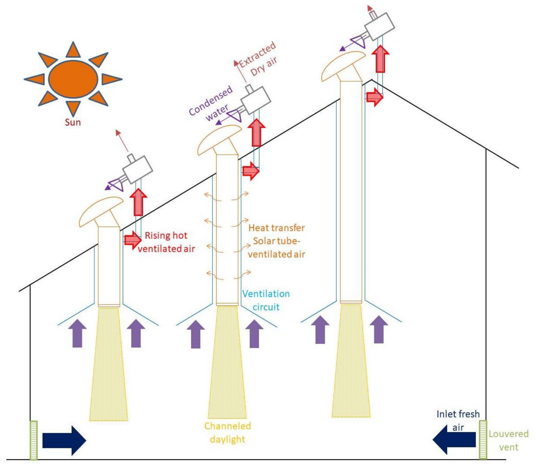
Accordingly, the novelty of the proposed SOLIVE system does not only consist in using daylighting and ventilation in the same building. The originality lies in transforming the solar tube into a dual–function optical thermal component able to transmit daylight and, at the same time, induce stack-driven airflow through the same solar-exposed element. This approach reduces the need for separate shafts or collectors and gives the solar tube an additional passive ventilation function.
The originality of this work can be summarized in five main points: (1) the solar tube is used as a daylighting conduit and as a thermal driver for natural ventilation, (2) the proposed architecture combines photometric transmission and buoyancy-induced airflow in one mathematical framework, (3) the system is intended for industrial and large-scale buildings where conventional windows may not provide sufficient daylighting and ventilation, (4) the optional moisture recovery cleaning concept is proposed as a possible response to dust accumulation in arid regions [
26] and (5) the design is assessed through key parameters including tube diameter, illuminated surface area, ventilated volume and seasonal solar conditions.
Compared with the hybrid passive systems reported in the literature, the present configuration is positioned at a different level of integration. Hybrid solar facade systems, solar chimney tunnel arrangements and solar-assisted ventilation devices generally combine separate architectural or service components whereas SOLIVE uses the solar tube itself as the common optical and thermal element. This distinction is important because the same roof-mounted component is used to transmit daylight and to generate buoyancy-driven airflow, which reduces the need for an additional shaft, facade collector or independent solar chimney.
Based on these gaps, the main contribution of this study is the design and performance assessment of a hybrid daylighting ventilation system supported by a mathematical model that combines solar geometry, optical transmission, tube heating, stack pressure and air change rate. The model permits the evaluation of the main design parameters under representative seasonal conditions and can be used as a first presizing tool before prototype development.
In this work, the assessment is limited to the two principal functions of SOLIVE, namely daylighting and passive ventilation. The moisture recovery cleaning subsystem is kept as a conceptual sustainability extension and is not experimentally evaluated here in order to maintain the focus on the optical and airflow mechanisms of the system.
The remainder of this article is organized as follows.
Section 2 describes the SOLIVE configuration, its operating principle, material selection and development workflow.
Section 3 presents the mathematical model, including the daylighting and buoyancy-driven ventilation equations and the adopted assumptions.
Section 4 discusses the numerical implementation, the validation scope, the parametric results, the sensitivity analysis, a comparison with standards, a comparison with standalone systems and an additional climatic assessment.
Section 5 gives the main conclusions, the research limitations and the future work.
3. Mathematical Modeling
3.1. Assumptions
Some key assumptions should be taken into consideration in order to simplify the complex thermodynamic and fluid dynamic behavior of the system without altering the correctness of the simulation results.
Dome and atmospheric transmissivities are assumed constant;
Solar tube reflectivity is assumed constant, with multiple reflections considered;
Illuminance depends mainly on direct solar radiation, tube efficiency and surface reflectance;
Air movement is driven only by buoyancy forces (wind effects are neglected).
Air density follows the ideal gas law, and the air flow velocity is estimated using Bernoulli’s principle;
The variations of atmospheric pressure and air density with height are neglected.
The indoor ambient temperature is assumed constant;
Clear sky conditions are assumed for the main simulations except in the independent daylighting comparison case.
These assumptions define the validity range of the simplified model. They make the numerical assessment suitable for preliminary design, parametric comparison and presizing. More detailed CFD and experimental investigations are still required before the final building-scale implementation.
The adopted assumptions are suitable for a preliminary sizing model since they isolate the main mechanisms considered in this study: optical transmission and buoyancy-driven airflow. Constant transmissivity and reflectivity correspond to clean or maintained surfaces and permit the effect of geometry to be studied separately from material degradation. Clear sky radiation is used to assess the solar potential of the system, whereas wind effects are neglected in order to focus on buoyancy forces only. The ideal gas relation and the Bernoulli equation are appropriate for low-speed natural ventilation estimates, while the constant indoor temperature assumption represents a quasi-steady design condition. The effect of these assumptions is discussed in the Limitations Section.
These assumptions were also classified according to their expected influence on the results, based on the literature dealing with natural ventilation, solar chimneys and solar radiation modelling [
5,
6,
7,
8,
19,
20,
27,
28,
29,
30,
31]. Constant optical properties have a moderate effect on illuminance prediction. The neglect of wind can have a significant effect on airflow, since wind pressure may assist or oppose the stack effect. The ideal gas and Bernoulli approximations have a minor to moderate effect for low-speed preliminary calculations. The neglect of pressure variation with height is minor for the compact height considered in this study. The constant indoor temperature assumption has a moderate effect while clear sky conditions have a significant effect on maximum performance because clouds directly reduce daylight transmission and solar heating.
The influence of these assumptions can also be interpreted from the governing equations. The illuminance response is almost proportional to the solar irradiance, the atmospheric transmissivity, the dome transmissivity and the reflective efficiency terms, while the ACH response varies with the square root of the stack-driving temperature difference and inversely with the ventilated volume. Consequently, uncertainties in the optical properties directly affect the predicted illuminance, whereas uncertainties in the temperature difference and the local pressure losses affect the airflow in a nonlinear but generally sublinear way. The neglect of wind remains the most important limitation for real buildings, because external pressure can either increase or reduce the buoyancy-driven flow depending on the wind direction and the facade exposure.
In practical applications, the steady-state assumption tends to smooth the short-term response of the system during transient cloud passages or rapid indoor load variations. The assumption of constant indoor temperature also neglects the coupling between the SOLIVE airflow and the thermal balance of the zone. These simplifications are acceptable for a first sizing approach, but they limit the accuracy of the model when applied to buildings with strong internal heat gains, intermittent occupancy, mechanical exhaust operation or exposed wind conditions.
3.2. Lighting
The lighting performance of the solar tube system can be mathematically modeled based on the following equations [
27,
28,
29,
30,
31].
The total transmitted solar power
Iout at the outlet of the solar tube is governed by
In Equation (1),
Ast is the solar tube aperture area at the dome inlet. It is calculated from the tube diameter as
Ast =
π·
Dst2 / 4. Thus, this value is directly obtained from the geometrical parameter
Dst listed in
Table 1 and is not an adjusted numerical coefficient.
The transmitted light by the dome
Id is given by
The effective sunlight on the solar tube’s dome
Ieff is given by
The incident angle of sunlight relative to the normal of the solar tube’s dome
θ is given by
The declination angle
δ is given by
The hour angle
h is given by
The solar time
ts is given by
In Equation (7), tl is the local civil time in hours, ts is the corrected solar time used for calculating the hour angle, ET is the equation of time in minutes, Lsm is the standard meridian and Ll is the local meridian. The values of −Lsm and Ll are fixed for the selected location while tl varies during the simulated day.
The equation of time
E is given by
The azimuth angle
γ is given by
The zenith angle
ζ is given by
The reflective efficiency
ηref of the solar tube is given by
The number of reflections
n that the light undergoes in the solar tube is given by
The bend efficiency
ηb is given by
3.3. Solar Tube Illuminance
The illuminance of the solar tube
Bst is given by
3.4. Ventilation
The ventilation performance of the ventilation tube system can be mathematically modeled based on the following equations.
The Air change rate (
ACH) is governed by
In Equation (16), the air mass flow rate induced in the ventilation tube around the solar is governed by
The air density
ρa is given by
The solar tube temperature
Tst is given by
The coefficient kst in Equation (18) represents an effective solar-to-temperature gain (kst = 0.05 K·m2/W). It is derived from a lumped steady-state energy balance in which the absorbed solar heat, qabs = Id × ηref × ηb × ηscat × Aabs, is balanced by the equivalent convective heat loss, qconv = Ueq × Aconv × (Ts − Tamb).
Therefore, Tst = Tamb + (Aabs/Ueq × Aconv) × Id × ηref × ηb × ηscat, where the term between the brackets is represented by kst. The value kst = 0.05 K·m2/W is used here as a preliminary coefficient for the considered compact tube/casing configuration and should be calibrated experimentally in future prototype tests.
The air velocity
νa is given by
The air pressure difference
ΔP caused by the stack effect is given by
The vent area
Avent caused by the stack effect is given by
4. Results and Discussion
4.1. Numerical Simulation
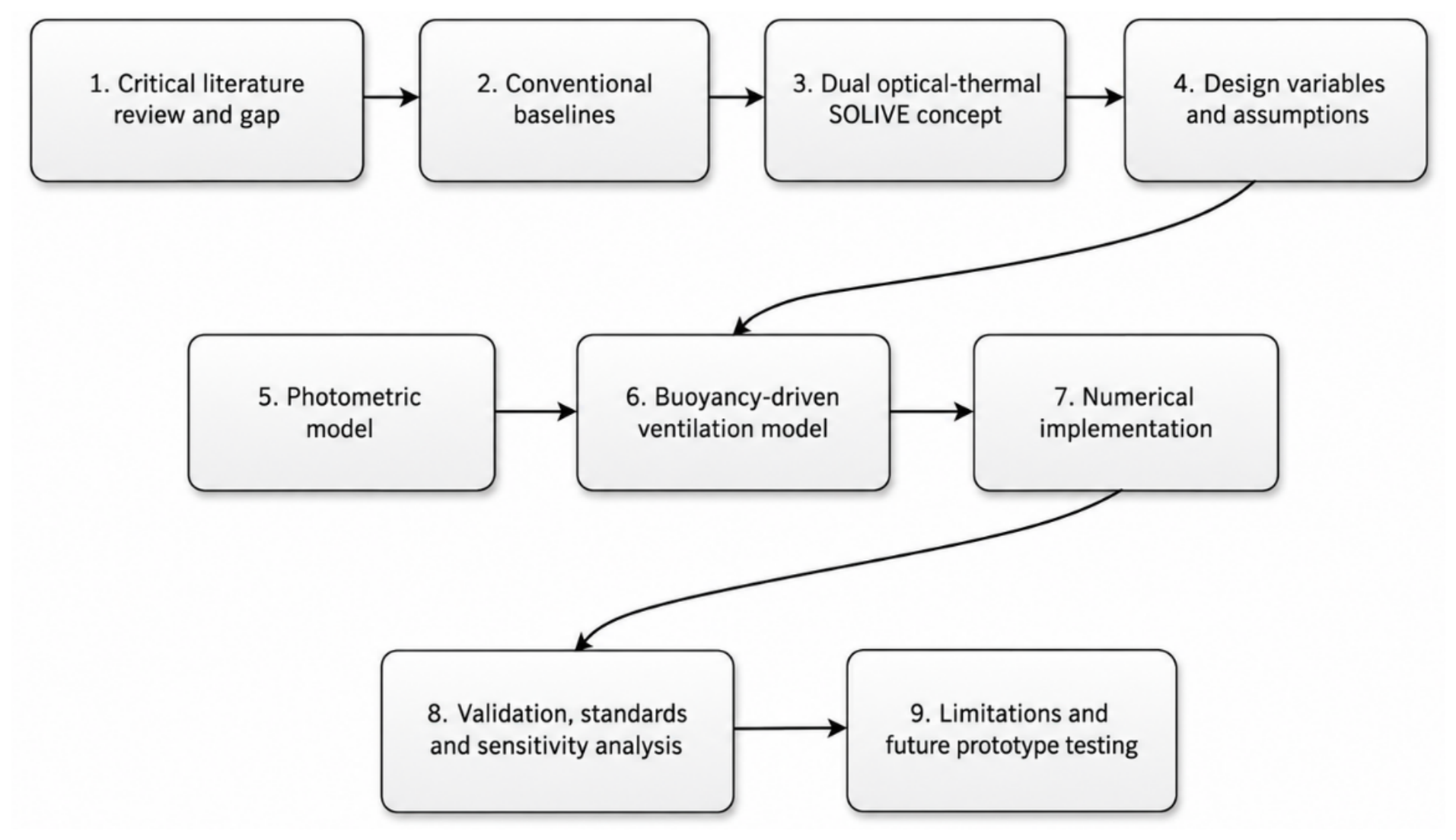
The numerical implementation follows the workflow shown in
Figure 2 and is based on the mathematical model presented in the previous Section. The photometric, thermal and aerodynamic equations were implemented step-by-step. For each reference day, the solar angles were first calculated and then used to determine the transmitted power, the illuminance, the solar tube temperature, the stack-pressure difference, the air velocity, the mass flow rate and the ACH. The simulations were carried out for the Equinox, Summer Solstice and Winter Solstice conditions.
4.2. Model Checking and Scope of Model Reliability
The numerical model was checked through three complementary steps: direct checking of the implemented governing equations, comparison of the daylighting submodel with independent light pipe experimental data and engineering plausibility checks through sensitivity analysis and benchmarking. These checks support the preliminary numerical assessment but they do not constitute an experimental validation of the complete integrated SOLIVE daylighting–ventilation system.
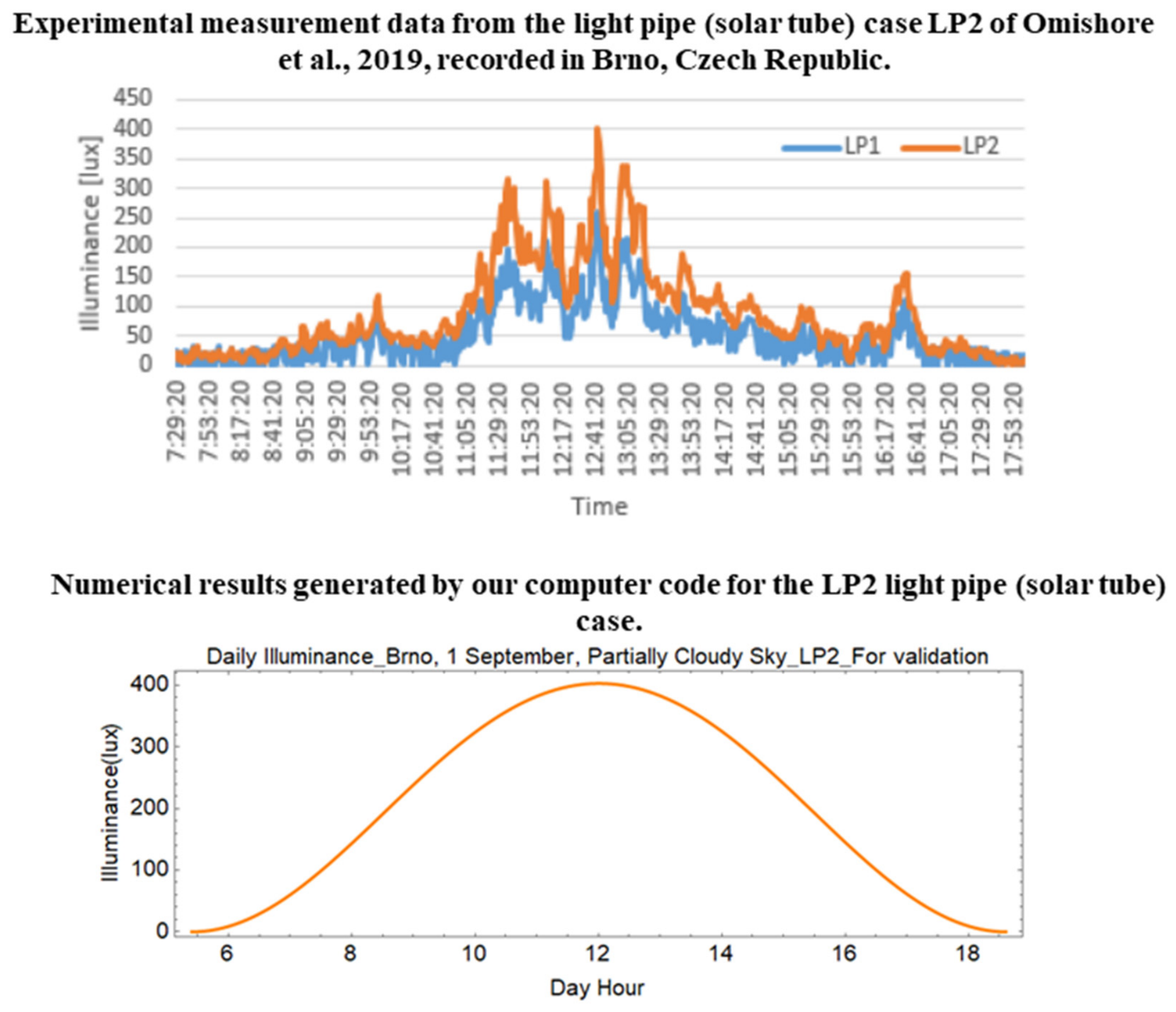
In order to evaluate the daylighting submodel, we numerically reproduced the case of the light pipe (LP2) examined in the work of Omishore et al. [
32]. The numerical results obtained by our computer code, in terms of the daily illuminance, are compared with the experimental results reported in [
32], recorded on 1 September 2017, in the city of Brno, Czech Republic (Latitude 49°12′, Longitude 16°37′). The characteristics of the studied light pipe (solar tube) were implemented in our model, and the sky condition was also taken into consideration. The numerical results are generally consistent with the measured data (
Figure 3).
It is also important to note that the fluctuations observed in the evolution of the measured illuminance are caused by the partly cloudy sky conditions, since the presence of passing clouds periodically obstructs direct sunlight. In contrast, our numerical model does not reproduce such short-term variability, because it cannot predict the exact moments when clouds block the sun. As a result, the numerical output appears as a smooth and continuous curve without fluctuations. Nevertheless, the numerical results remain generally consistent with the experimental data, as they accurately follow the overall trend of the measured illuminance.
The Brno case verifies the daylighting submodel and the computer implementation before applying the code to the Bisha climatic conditions. Thus, the comparison supports the photometric part of the model only. The ventilation part is based on the stack effect formulation and on an order of magnitude comparison, and the integrated daylighting–ventilation system still requires prototype testing and/or CFD validation.
For the ventilation module, an order of magnitude comparison was carried out using the experimental solar chimney study of Raghuwanshi and Bartaria [
22], where ventilation flow rates of 0.2–0.4 m
3/s were reported. For the most favorable SOLIVE case (
Dst = 0.3 m,
Vvs = 20 m
3 and peak
ACH = 20.5 h
−1), the corresponding volumetric airflow is
Q =
ACH × V
vs/3600 = 0.114 m
3/s. This value is lower than, but still of the same order as, the experimental range reported in [
22], which is acceptable considering the compact height and simplified vent geometry used in the present model. The comparison indicates a plausible airflow magnitude for the simplified SOLIVE configuration.
This comparison should be regarded as a plausibility benchmark rather than a full validation of the SOLIVE airflow path. A direct validation of the ACH requires either a prototype measurement campaign or a CFD benchmark reproducing the same inlet, outlet, tube/casing geometry and boundary conditions. Therefore, the airflow predictions are suitable for preliminary sizing and relative comparison but not yet for final building design without additional validation.
At this stage, the credibility of the model is supported by the daylighting comparison with an independent light pipe experiment, by the order of magnitude comparison with the reported solar chimney airflow data and by consistency checks against the governing physical relations. These checks do not replace a full validation of the coupled optical thermal ventilation path. A higher level of confidence will require either CFD simulations using the same geometry and boundary conditions or experimental measurements on a scaled or full-scale SOLIVE prototype.
4.3. Simulation Data
The numerical simulations are carried out to pre-size the proposed design under the following data:
Table 1.
Simulation data.
Table 1.
Simulation data.
| Description | Symbol | Value |
|---|
| Illuminated surface area | | 5; 10; 15 m2 |
| Solar tube diameter | | 0.1; 0.2; 0.3 m |
| Solar reference day | d | 80 (Equinox); 171 (Summer Solstice); 355 (Winter Solstice) |
| Daylight efficacy | | 120 lm/W |
| Gravitational acceleration | g | 9.81 m/s2 |
| Vertical vent height | H | 0.2 m |
| Solar irradiance | I | 1367 W/m2 |
| Standard meridian | | 0.79 rad |
| Local meridian | | 0.70 rad |
| Atmospheric pressure | | 101,325 Pa |
| Universal gas constant | R | 287 J/kg·K |
| Ambient temperature | | 303.75 K |
| Ventilated space volume | | 20; 40; 60 m3 |
| Angle of bend | | 0.52 rad |
| Tilt angle of the dome | | 0.37 rad |
| Latitude angle | | 0.37 rad |
| Light distribution and scattering efficiency | | 0.85 |
| Average angle of incidence on inner tube surface | | 0.52 rad |
| Atmospheric transmission coefficient | | 0.8607 |
| Dome transmission coefficient | | 0.9 |
| Reflectance of the solar tube inner surface | | 0.95 |
4.4. Lighting Performance
The lighting performance of the proposed SOLIVE system is assessed during 3 solar reference days of the year: Equinox, Summer Solstice and Winter Solstice. The lighting performance during any other day of the year can be assessed using the same developed simulation code.
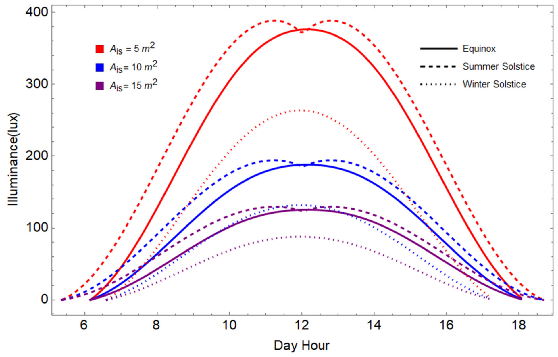
Figure 4 illustrates the daily evolution of the indoor illuminance for one single solar tube during the Equinox, Summer Solstice and Winter Solstice days, from sunrise to sunset, for different illuminated surface areas Ais in the region of Bisha.
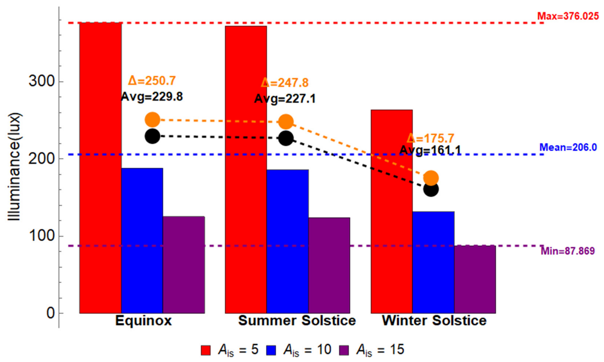
Figure 4 is complemented by
Figure 5, which presents the maximum illuminance values as a function of the Ais and the solar reference day.
Around noon, the illuminance reaches an overall maximum of approximately 376 lux during the Equinox for an illuminated surface area Ais of 5 m2, while the overall minimum is approximately 87.9 lux for an Ais of 15 m2 during the Winter Solstice. When the Ais increases from 5 m2 to 10 m2, the corresponding illuminance reduction is about 251 lux during the Equinox and about 176 lux during the Winter Solstice.
As is expected, the simulation results clearly show that smaller illuminated surfaces receive higher illuminance levels compared to larger ones. This phenomenon arises from the inverse relationship between the illuminance and the Ais over which the light is distributed. As the Ais increases, the same amount of light energy is spread over a larger area, leading to a more significant reduction in illuminance per unit area.
As shown in
Figure 5, the illuminance reduction is more pronounced when the Ais increases from 5 m
2 to 10 m
2 than when it increases from 10 m
2 to 15 m
2.
This behavior is explained by the nonlinear effect of light distribution over the illuminated surface area Ais. Increasing the Ais from a small to a medium value strongly reduces the light concentration and therefore causes a higher illuminance decrease. However, increasing the Ais from a medium to a larger value produces a more moderate additional reduction in illuminance.
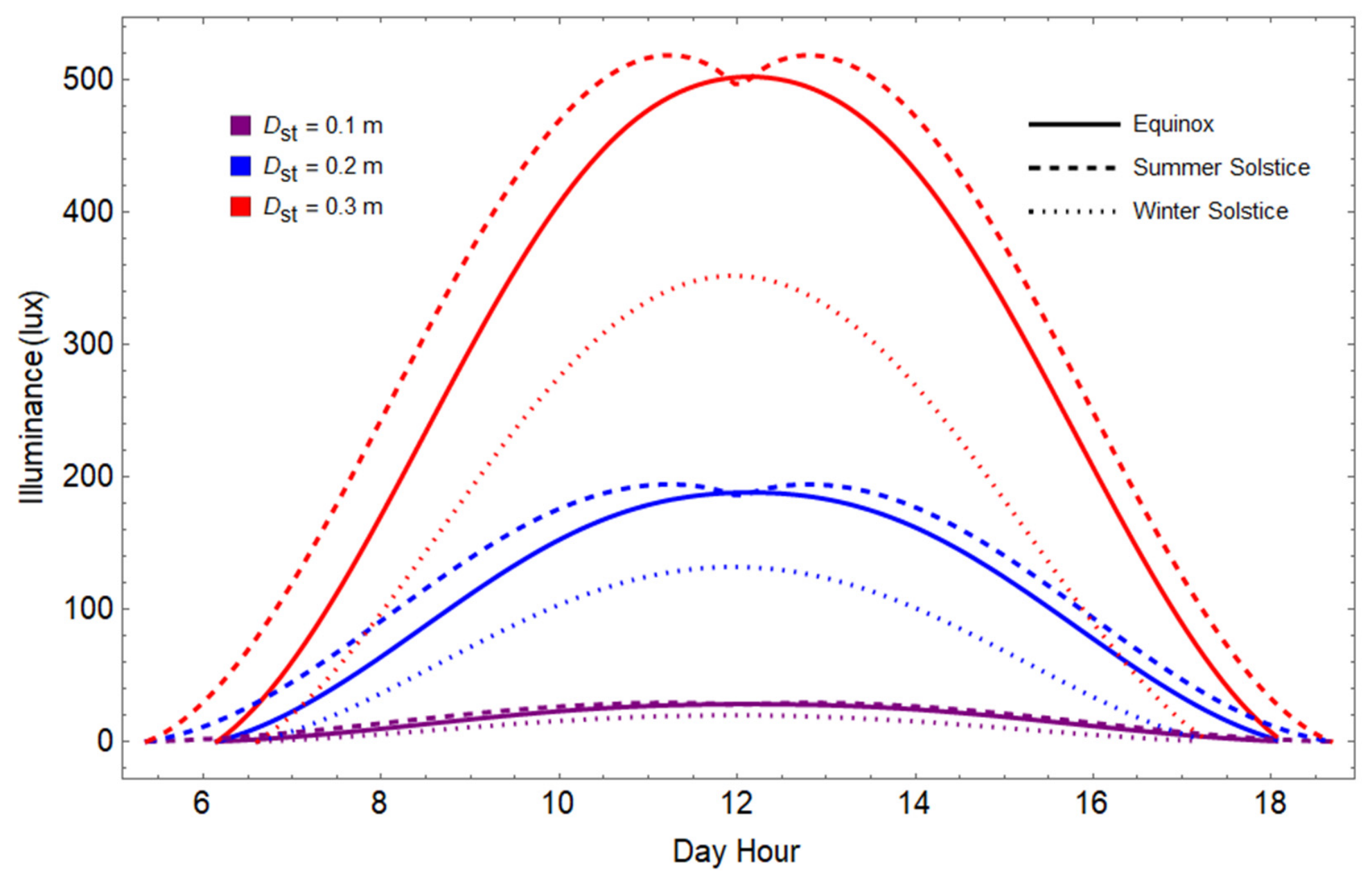
Figure 6 illustrates the daily illuminance evolution of one single solar tube during the Equinox, Summer Solstice and Winter Solstice days, from sunrise to sunset, for different solar tube diameters Dst in the region of Bisha, Saudi Arabia.
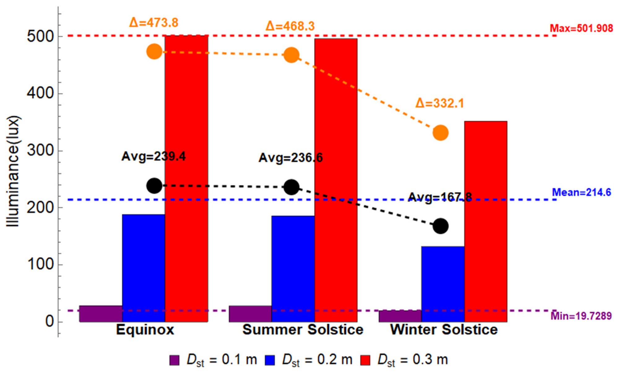
Figure 6 is complemented by
Figure 7, which presents the maximum illuminance values as a function of the Dst and the solar reference day.
Around noon, the illuminance reaches an overall maximum of approximately 502 lux during the Equinox for a solar tube diameter Dst of 0.3 m, while the overall minimum is approximately 20 lux for a Dst of 0.1 m during the Winter Solstice. When the Dst increases from 0.1 m to 0.3 m, the corresponding illuminance gain is about 474 lux during the Equinox and about 332 lux during the Winter Solstice.
The results across the three solar reference days demonstrate a strong dependence of the interior illuminance on the solar tube diameter and the seasonal variations in solar radiation. Larger solar tube diameters consistently allow more daylight to penetrate, with a more pronounced impact during the Summer Solstice and Equinox.
The Winter Solstice presents the lowest illumination due to limited solar availability. The illuminance gain is more pronounced for larger solar tube diameters, because the light-collecting area increases with the square of the diameter. Additionally, larger tubes reduce internal reflection losses, which enhance light transmission and make the illuminance gain more significant at higher diameters.
The obtained results underline the importance of appropriately sizing the solar tubes to meet the seasonal daylighting needs. Larger diameters provide more consistent illuminance levels and are particularly effective in maximizing daylighting performance across all the seasons.
Overall, the simulation results show that the effects of the illuminated surface area and the solar tube diameter are governed by the daily variation of the solar altitude. The highest illuminance is concentrated around noon, while a sharp decrease is observed in the early morning and the late afternoon. The illuminance distribution follows a bell-shaped curve throughout the day, with the peak reached near solar noon, when the received solar radiation is maximum. The decline in illuminance during the morning and evening hours is mainly caused by the lower solar elevation angle.
The slight difference in illuminance levels during the Equinox and Summer Solstice can be attributed to several interconnected factors. In fact, both the solar reference days present optimal solar angles at noon, resulting in similar light collection efficiency due to the solar tube’s reflective design, which ensures consistent performance under varying solar angles. In addition, a similar atmospheric transmissivity and Bisha’s geographic location near the Tropic of Cancer limit the variations in solar radiation intensity between the two solar reference days. Furthermore, the physical limitations of the solar tube’s design cap its performance, preventing significant increases in illuminance despite higher solar radiation during the Summer Solstice.
These combined factors stabilize the illuminance levels, resulting in only minor seasonal differences between the Equinox and the Summer Solstice. The extended hours of daylight during the Summer Solstice result in a broader distribution of illumination throughout the day. In addition, it is important to note that higher illuminance levels during the Summer Solstice are sustained over a longer period around noon due to both extended daylight hours and higher solar altitudes. The steeper illuminance gradient in the morning and in the evening highlights the impact of the extended daylight hours, where the sun remains above the horizon for longer durations.
The remarkable deterioration in illuminance during the Winter Solstice compared to the Equinox and the Summer Solstice is principally due to the sun’s lower altitude in the sky during the Winter and shorter daylight hours. This results in a higher solar zenith angle, which reduces the intensity of direct sunlight entering the solar tube. Furthermore, the increased angle causes the sunlight to traverse a longer path through the atmosphere, leading to greater scattering and absorption of light. Thus, less light reaches the solar tube, and the amount transmitted to the illuminated surface is significantly reduced. The reduced daylight duration also leads to a narrower distribution of illuminance throughout the day, with peaks occurring around noon when the solar radiation is at its highest.
4.5. Ventilation Performance
The ventilation performance of the proposed SOLIVE system is assessed during 3 solar reference days of the year: Equinox, Summer Solstice and Winter Solstice. The ventilation performance during any other day of the year can be assessed using the same developed simulation code.
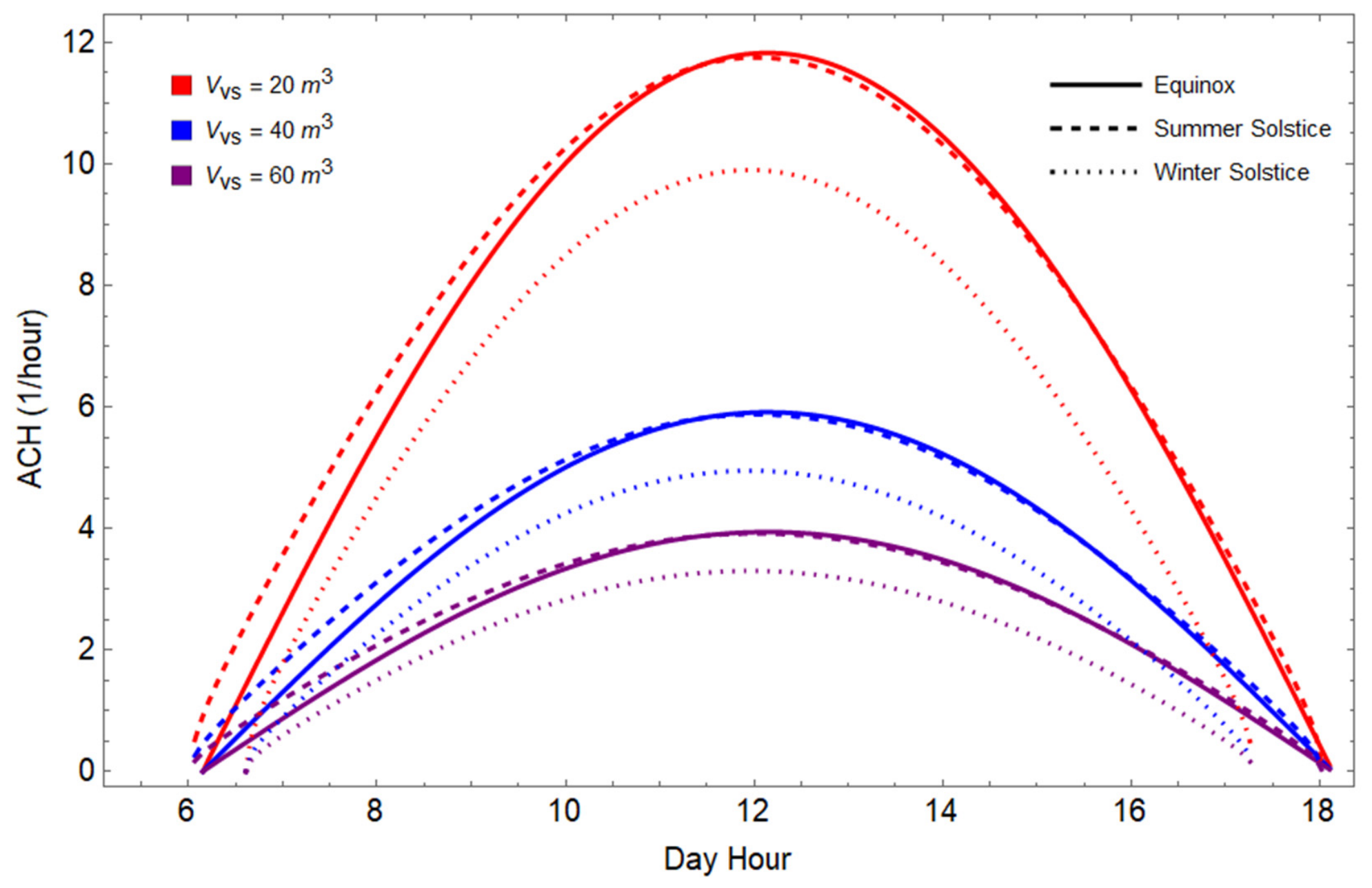
Figure 8 illustrates the daily ACH evolution of one single solar tube during the Equinox, Summer Solstice and Winter Solstice days, from sunrise to sunset, for different ventilated space volumes Vvs in the region of Bisha, Saudi Arabia.
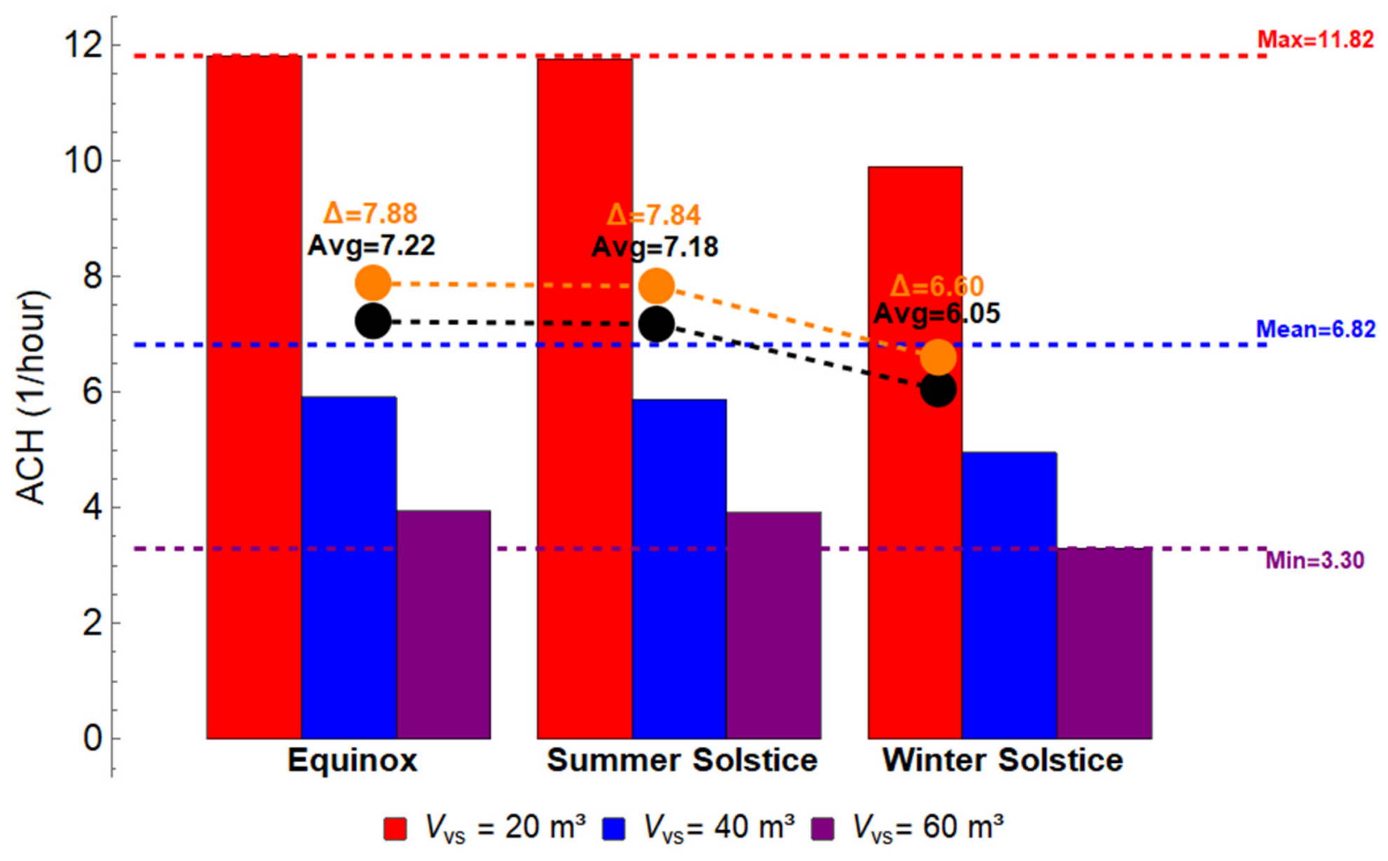
Figure 8 is complemented by
Figure 9, which presents the maximum ACH values as a function of the Vvs and the solar reference day.
Around noon, the ACH reaches an overall maximum of approximately 12 h−1 during the Equinox for a ventilated space volume Vvs of 20 m3, while the overall minimum is approximately 3.5 h−1 for the same volume during the Winter Solstice. When the Vvs increases from 20 m3 to 60 m3, the corresponding ACH reduction is about 7.9 h−1 during the Equinox and about 6.60 h−1 during the Winter Solstice.
As expected, smaller ventilated volumes provide higher ACH values than larger volumes, because the ACH is inversely proportional to the Vvs. The ACH reduction is more pronounced when the Vvs increases from 20 m3 to 40 m3 than when it increases from 40 m3 to 60 m3. As the Vvs increases, the same airflow is distributed over a larger volume, reducing the number of air exchanges per hour. This nonlinear relationship explains why volume selection is important when adapting the system to real-building spaces.
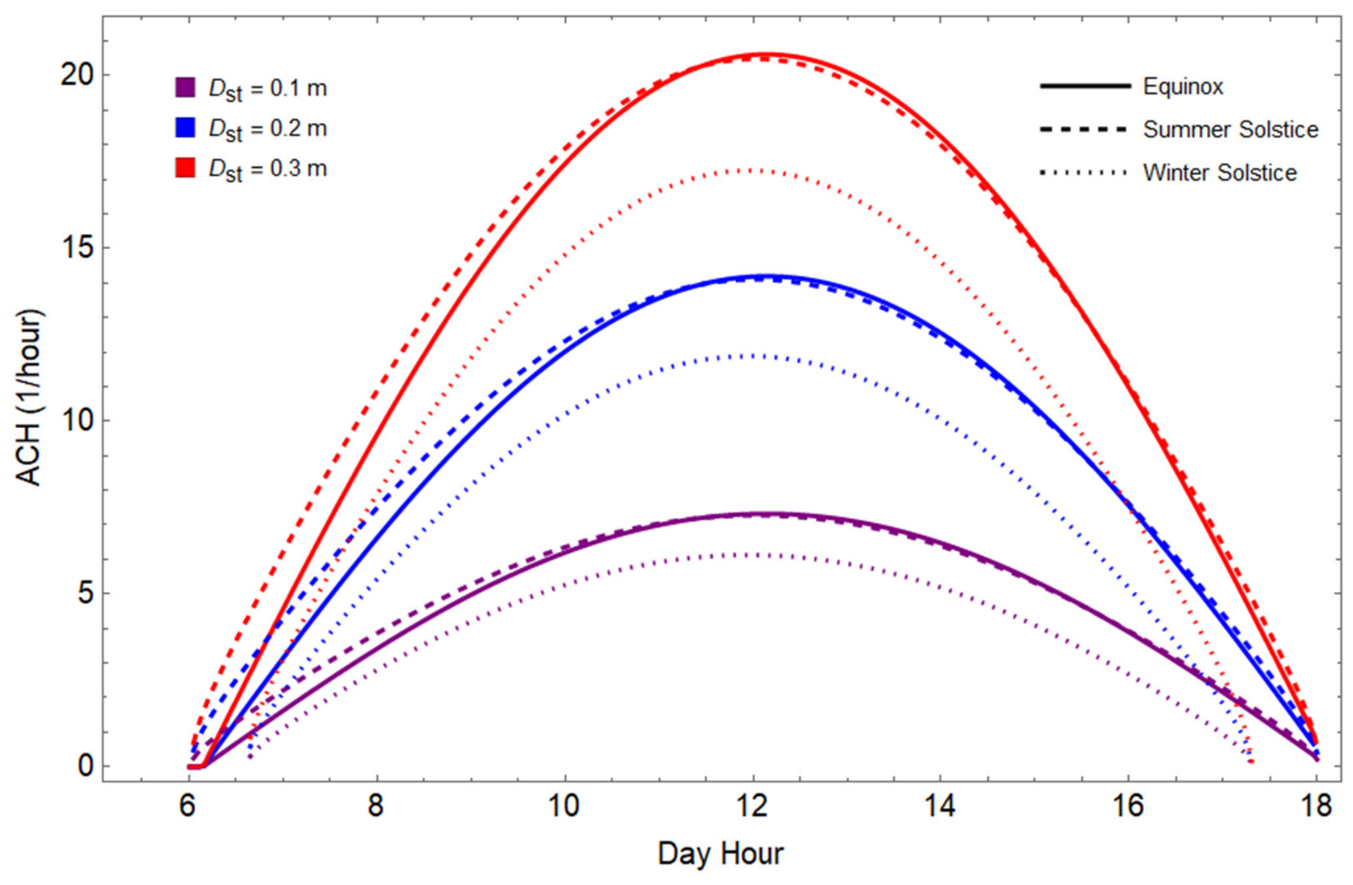
Figure 10 illustrates the daily ACH evolution of one single solar tube during the Equinox, Summer Solstice and Winter Solstice days, from sunrise to sunset for different solar tube diameters Dst in the region of Bisha, Saudi Arabia.
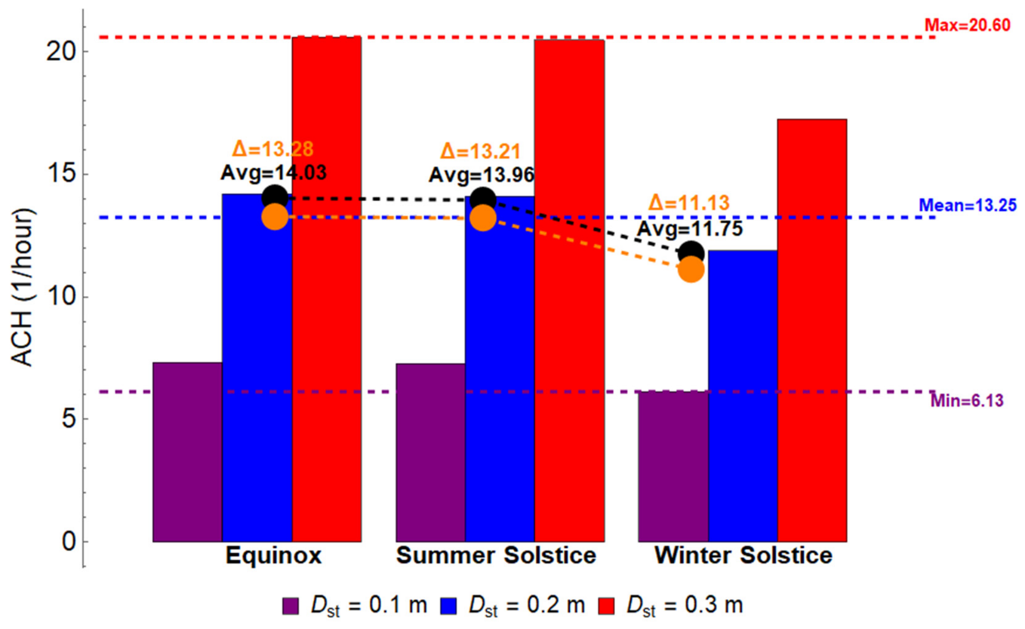
Figure 10 is complemented by
Figure 11, which presents the maximum ACH values as a function of the Dst and the solar reference day.
Around noon, the ACH reaches an overall maximum of approximately 20.5 h−1 during the Equinox for a solar tube diameter Dst of 0.3 m, while the overall minimum is approximately 6.1 h−1 for a Dst of 0.1 m during the Winter Solstice. While the absolute maximum ACH values, without coupling to the interior temperatures or the building requirements, may exceed those encountered in practice, they reflect the inherent potential of the solar tube to drive ventilation. When the Dst increases from 0.1 m to 0.3 m, the corresponding ACH gain is about 13.3 h−1 during the Equinox and about 11.1 h−1 during the Winter Solstice.
The influence of the solar tube diameter on the ACH is significant, as a larger diameter allows more solar radiation to enter the tube and enhances the heating of the air within the ventilation path. This heating drives a stronger buoyancy effect and improves the natural ventilation. In contrast with the nonlinear effect of the ventilated space volume Vvs, the influence of the Dst on the ACH remains relatively regular, because increasing the tube diameter consistently enhances the solar radiation capture and the thermal driving potential for airflow.
The bell-shaped curves of air change per hour (ACH) across all the scenarios—Equinox, Summer Solstice and Winter Solstice—are a result of the daily solar radiation pattern and the heat generated by the sunlight captured through the solar tube. This heat creates a temperature gradient that drives natural ventilation, as the warm air inside the space rises and escapes, pulling cooler air in to replace it. The intensity of solar radiation is highest around noon, leading to the greatest heat generation and, thus, the peak ACH values. During the early morning and the late afternoon, when the solar angles are low and the radiation intensity is minimal, the heat generation is insufficient to sustain strong ventilation, resulting in lower ACH values. Seasonal variations influence the amount of solar heat produced, with the Equinox and the Summer Solstice exhibiting the highest peaks, while the Winter Solstice shows the lowest peaks.
In all the simulation results about the effects of the ventilated space volume and the solar tube diameter, the difference in the ACH levels between the Equinox and the Summer Solstice is very slight, since the solar angles and the daylight durations during these periods are relatively similar in the region of Bisha, Saudi Arabia, resulting in comparable solar radiation intensity and heat generation inside the ventilated space. This consistency ensures that the buoyancy-driven ventilation facilitated by the solar tube remains nearly uniform between these two periods. However, during the Winter Solstice, the sun is lower in the sky, leading to reduced solar radiation and heat generation. Therefore, the temperature difference driving the buoyancy effect is diminished, resulting in lower ACH levels compared to the Equinox and the Summer Solstice. This seasonal variation explains why the ACH levels are notably reduced during the Winter Solstice.
The observed tendencies can be generalized using the scaling relations contained in the model. The transmitted illuminance increases with the solar tube aperture area and therefore approximately follows a Dst2 trend when the optical efficiencies remain unchanged, while it decreases when the same luminous flux is distributed over a larger illuminated surface Ais. For ventilation, the volumetric flow rate follows Q = Avent × Sqrt(2 × g × H × ΔT/Tamb) and ACH = 3600 × Q/Vvs.
This relation explains why the effect of ventilated volume is inversely proportional, whereas the effect of tube heating is sublinear, because the velocity depends on the square root of the temperature difference.
For the most favorable operating case, the estimated Grashof and Rayleigh numbers are of the order of 107, indicating that buoyancy-driven natural convection is physically consistent with the predicted airflow. However, these dimensionless numbers also show that local losses, turbulence, inlet/outlet geometry and boundary layer development may influence the real flow field. This reinforces the need for CFD analysis and prototype testing in the next stage of development.
These physical trends lead to several design tradeoffs. Increasing the tube diameter improves the daylighting and enhances the thermal driving force for ventilation, but it also increases the roof opening, the structural integration requirements, the material cost and the possible glare risk near the diffuser. Similarly, reducing the illuminated area increases the local illuminance but may reduce the spatial uniformity while increasing the ventilation volume and decreasing the ACH for the same airflow rate. Thus, the optimal configuration should be selected by balancing illuminance level, airflow demand, visual comfort, architectural constraints and installation cost.
4.6. Sensitivity Analysis
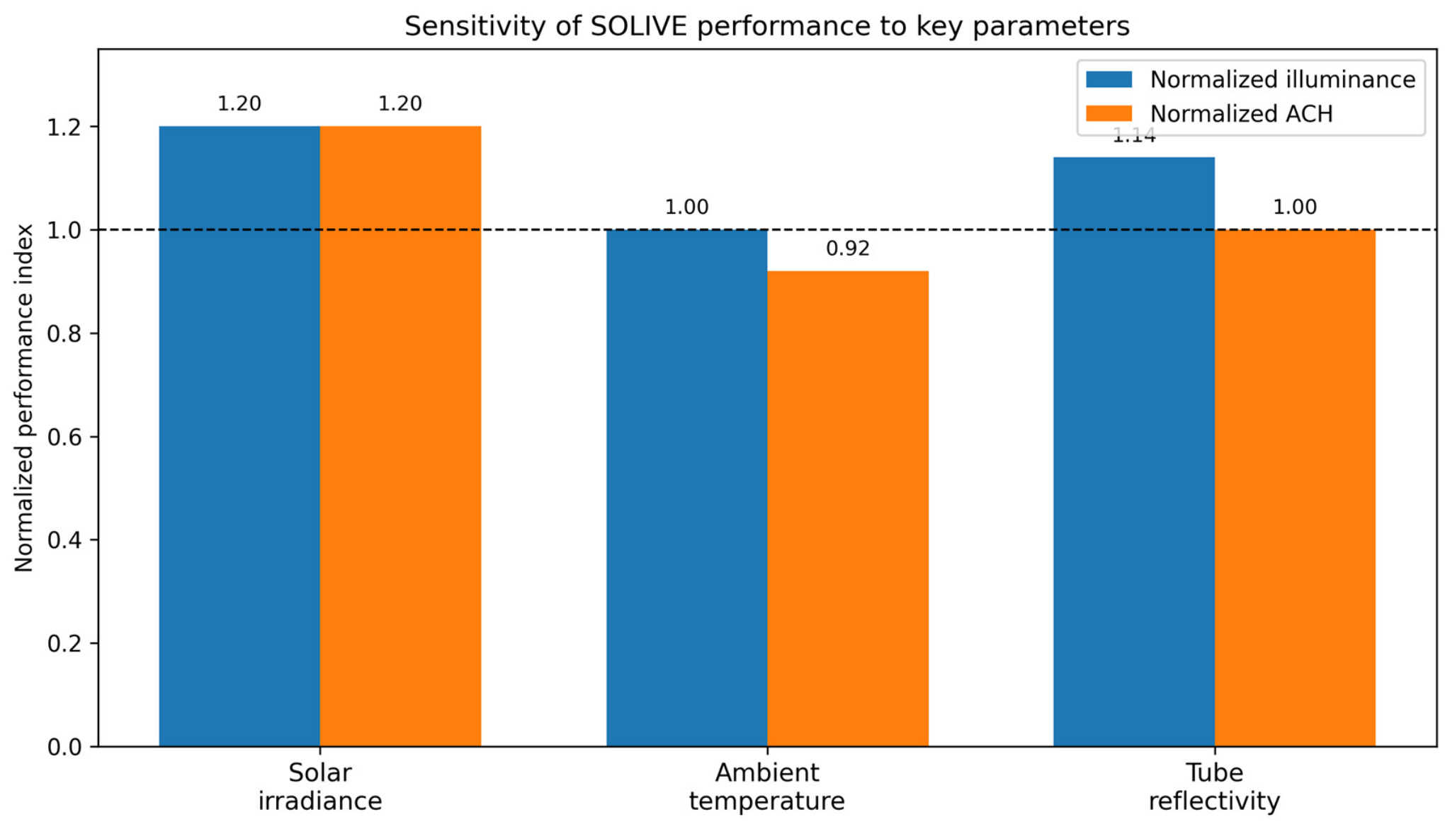
To evaluate the robustness of the developed mathematical model and to better understand the influence of the environmental and material parameters on the system performance, a sensitivity analysis was conducted. The analysis focuses on three important variables that can vary in real operating conditions: solar irradiance, ambient temperature, and the reflectivity of the solar tube inner surface. These parameters directly influence both the optical efficiency of the daylighting system and the buoyancy-driven airflow responsible for natural ventilation.
The graphical summary of these trends is presented in
Figure 12 in order to facilitate a comparison between the daylighting and ventilation responses.
4.6.1. Influence of Solar Irradiance
Solar irradiance is a key parameter affecting both the daylight transmission and the thermal buoyancy inside the solar tube. An increase in the solar irradiance directly increases the amount of light entering the tube and also enhances heat generation along the tube surface, which intensifies the stack effect driving natural ventilation.
The sensitivity analysis indicates that higher solar irradiance values lead to proportional increases in both illuminance levels and air change rates (ACHs). For instance, an increase in the solar irradiance enhances the optical power entering the tube and therefore increases the interior illuminance, particularly during periods close to solar noon when the radiation intensity is highest. Similarly, stronger solar radiation raises the temperature difference between the heated tube surface and the surrounding air, which amplifies the buoyancy-driven airflow and consequently improves the ventilation performance.
These results highlight that the system performs most efficiently in regions characterized by high solar availability, confirming its suitability for sunny climates such as those found in the Middle East and North Africa.
4.6.2. Influence of Ambient Temperature
Ambient temperature influences the density difference between the air inside the solar tube and the surrounding environment, which is a driving factor for natural convection. The buoyancy-driven airflow responsible for ventilation is proportional to the temperature gradient between the heated air inside the tube and the ambient air.
The sensitivity analysis shows that higher ambient temperatures slightly reduce the ventilation driving force, because the temperature difference between the heated tube surface and the surrounding air becomes smaller. As a result, the buoyancy effect may be moderately reduced under very hot conditions. However, the solar heating along the tube surface still maintains a sufficient temperature gradient to sustain natural airflow.
Therefore, although ambient temperature variations affect the magnitude of the airflow, the overall ventilation mechanism remains effective across a wide range of climatic conditions.
4.6.3. Influence of Solar Tube Reflectivity
The reflectivity of the inner surface of the solar tube plays a crucial role in determining the optical efficiency. Higher reflectivity values reduce optical losses caused by multiple reflections inside the tube and increase the amount of transmitted daylight reaching the indoor space.
The sensitivity analysis demonstrates that small reductions in reflectivity can significantly affect illuminance levels, especially for longer tubes where light undergoes multiple reflections. Maintaining high reflectivity coatings is therefore essential for preserving daylighting performance.
This observation highlights the importance of material selection and maintenance strategies for solar tubes, particularly in dusty environments where surface degradation may occur over time.
4.6.4. Implications for System Design
The sensitivity analysis confirms that the performance of the proposed hybrid system is strongly influenced by environmental and material parameters. High solar irradiance improves both daylighting and ventilation efficiency, while appropriate material reflectivity ensures optimal optical performance. Ambient temperature variations moderately influence the ventilation mechanism but do not compromise the overall functionality of the system.
These results provide valuable guidance for design optimization and system deployment, particularly in regions characterized by strong solar radiation and arid climatic conditions.
Figure 12 summarizes the sensitivity trends using normalized performance indices. It shows that solar irradiance affects both illuminance and ACH, ambient temperature mainly affects ACH through the buoyancy gradient and tube reflectivity mainly affects illuminance because it controls optical losses after multiple reflections.
4.6.5. Quantitative Sensitivity and Uncertainty Indicators
Because the model is deterministic and no repeated experimental measurements are available for the complete SOLIVE system, statistical confidence intervals cannot yet be calculated. Instead, quantitative local sensitivity indicators were added (
Table 2) to show how the selected input variations propagate to the two main outputs. These indicators are derived from the governing equations and from the parametric trends discussed above, and they provide an initial uncertainty frame for a preliminary design.
4.7. Comparison with Standards
The simulated illuminance and ventilation values were compared with the international standards only as indicative benchmarks for practical relevance. According to ISO 8995-1 [
33], the recommended illuminance for many industrial tasks is around 200 lux; the proposed SOLIVE configuration provides maximum values of approximately 376–502 lux depending on the tube diameter and the illuminated area, while lower values occur for larger areas during the Winter Solstice. Similarly, the ACH values were compared with the ventilation intent of ASHRAE 62.1 [
34] as a preliminary reference for indoor air renewal. This comparison should not be interpreted as proof of full compliance in real buildings, because glare, daylight uniformity, thermal comfort, occupancy patterns, wind effects, envelope leakage and HVAC integration were not fully modelled.
The obtained results provide important insights for the design and optimization of hybrid solar daylighting–ventilation systems. In particular, the solar tube diameter appears to be one of the most influential parameters affecting both the lighting and ventilation performance. Increasing the tube diameter significantly improves the solar radiation capture, which enhances both the optical transmission and the thermal buoyancy responsible for airflow generation. However, practical considerations such as installation constraints, structural integration, and cost must be considered when selecting optimal tube dimensions. Furthermore, seasonal variations in solar radiation highlight the importance of adapting the system configurations to the local climatic conditions. In regions with strong solar availability, such as arid and semi-arid climates, the proposed system may provide substantial reductions in building energy demand by simultaneously reducing artificial lighting requirements and supporting natural ventilation.
Although the present assessment focuses on illuminance and air change rate, indoor environmental quality is broader than these two indicators. For daylighting, visual comfort also depends on glare, luminance contrast, daylight uniformity and the spatial distribution of light on the working plane. For ventilation, thermal comfort depends on air temperature, mean radiant temperature, air speed, humidity and occupant activity. Therefore, the obtained lux and ACH values should be interpreted as first performance indicators while future building-scale studies should include glare analysis, daylight uniformity, thermal comfort indices and humidity effects.
4.8. Comparison with Standalone Daylighting and Ventilation Systems
To support the novelty of the proposed configuration, the integrated SOLIVE system was compared with two standalone passive systems under the same representative conditions:
Dst = 0.3 m,
Ais = 5 m
2,
Vvs = 20 m
3, Equinox, noon and Bisha climatic data. The comparison, summarized in
Table 3, focuses on the functional integration rather than on the optimization of each standalone technology.
4.9. Additional Climatic Assessment
Since the SOLIVE performance depends on solar altitude, irradiance and ambient conditions, an additional climatic assessment was conducted using the same representative geometry (
Dst = 0.3 m,
Ais = 5 m
2 and
Vvs = 20 m
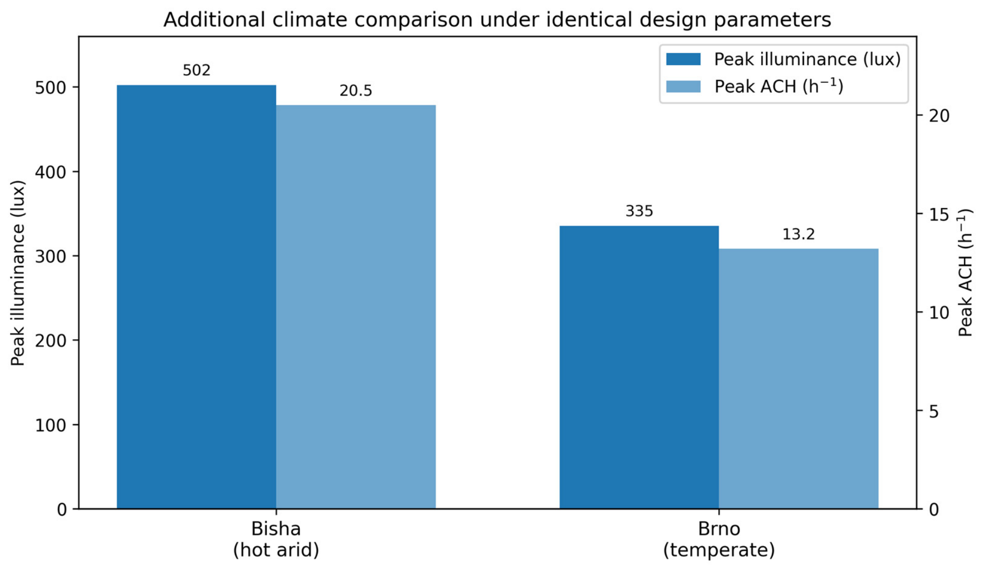
3). Bisha represents the original hot arid case with high solar availability. Brno, Czech Republic, was selected as a temperate continental comparison case because it was already used for the daylighting validation. The comparison, presented in
Table 4, illustrates the expected performance change when the same design is applied in a higher-latitude and less-solar-favorable climate.
Figure 13 depicts a comparison of peak illuminance and ACH between the Bisha and Brno climate for the same SOLIVE design parameters.
The additional climatic case shows that the peak illuminance decreases by about 33% and the peak ACH decreases by about 36% compared with Bisha. These results confirm that the system is more suitable for high solar availability climates, but it can still operate in temperate climates with lower expected performance.
In cold climates, the lower solar altitude and shorter daylight duration may reduce both the daylight transmission and the solar heating of the tube, although a larger indoor–outdoor temperature difference can partially support the stack-driven airflow. In humid climates, cloud cover and diffuse radiation may reduce direct solar gains, while the introduction of outdoor air can increase latent loads if humidity control is not considered. Therefore, the SOLIVE system is expected to be most effective in hot arid and sunny climates, but its use in cold or humid regions requires site-specific sizing, condensation control and integration with the building envelope and the HVAC strategy.
4.10. Benchmarking with Related Passive and Hybrid Systems
A broader benchmark was added to position the SOLIVE concept against similar passive daylighting, ventilation and hybrid systems reported in the literature. The comparison, presented in
Table 5, is not fully one-to-one because each reference system was developed for a different geometry, climate and objective. However, it clarifies the contribution of SOLIVE by identifying whether the compared systems provide daylighting, ventilation or both functions simultaneously.
4.11. Indicative Energy, Cost and CO2 Saving Implications
A complete technoeconomic and life-cycle assessment requires hourly building loads, local electricity tariffs, system costs and grid emission factors. Nevertheless, a first-order comparison can be made by converting the delivered daylight and airflow into the equivalent avoided electric lighting and fan power. For a 5 m2 illuminated zone requiring 200 lux, the equivalent luminous flux is 1000 lm. With an LED efficacy of 100 lm/W, this corresponds to about 10 W of avoided artificial lighting per SOLIVE module during useful daylight hours.
For ventilation, the most favorable SOLIVE case gives ACH = 20.5 h−1. Supplying the same airflow mechanically would require fan power that depends on pressure rise and fan efficiency. For a representative pressure rise of 50–150 Pa and a fan efficiency of 0.5, the equivalent fan power is approximately 11–34 W. Thus, the combined avoided electrical demand can be estimated at about 21–44 W per module during simultaneous daylighting and ventilation operation. The corresponding annual energy and CO2 savings can be calculated by multiplying this avoided power by the operating hours and by the local grid emission factor. These values are indicative and should be refined through a whole building energy simulation in future work.
5. Conclusions
The main conclusions of this study are summarized as follows:
The proposed SOLIVE system integrates tubular daylighting and buoyancy-driven passive ventilation in one solar-exposed architectural component.
The developed model combines solar geometry, optical transmission, solar tube heating, stack pressure and an air change rate calculation, providing a preliminary sizing tool for the system.
For the Bisha reference climate, the system reaches peak illuminance values of about 376–502 lux and peak ventilation performance up to about 20.5 ACH, depending on the tube diameter, the illuminated area and the ventilated volume.
The solar tube diameter is the most influential parameter because it increases both the collected light and the thermal driving potential for airflow.
The additional Brno climate case shows a lower performance under higher-latitude and lower-solar-availability conditions, which confirms the need for site-specific design adaptation.
The comparison with standalone solar tubes and standalone solar chimneys supports the novelty of SOLIVE as an integrated, multifunctional system, while the limitations indicate that prototype validation and CFD analysis are still required before building implementation.
The main limitations of the present work are the simplified airflow model, the neglect of wind effects, the absence of direct prototype validation and the preliminary treatment of energy, cost and CO2 savings.
The obtained results are valid within the scope of the adopted modelling approach. The daylighting submodel was compared with independent experimental light pipe data, while the ventilation behavior was assessed using a simplified stack effect model, an order of magnitude comparison and engineering plausibility checks. Therefore, the integrated daylighting–ventilation system should still be validated by prototype testing and/or CFD simulations before final building implementation.
5.1. Research Limitations
The present study is a preliminary design and numerical assessment rather than a complete experimental demonstration. Firstly, the daylighting model assumes constant dome transmissivity, atmospheric transmissivity and tube reflectivity while real systems may be affected by dust deposition, material aging and variable sky conditions. Secondly, wind-driven ventilation, turbulence, local pressure losses, indoor thermal stratification, occupant effects and building-envelope leakage were not considered; therefore, the predicted ACH values represent the buoyancy-driven potential under simplified conditions. Thirdly, a constant indoor temperature and clear sky conditions were assumed for the main simulations, which limits the applicability of the results to transient, occupied and cloudy real-building conditions. Fourthly, the ventilation module was checked by analytical formulation and order of magnitude comparison with solar chimney data, while direct validation using measurements from a SOLIVE prototype or detailed CFD simulations remains necessary. Finally, the empirical thermal gain coefficient used in the tube temperature equation requires future calibration for specific materials, tube lengths and casing geometries.
The moisture recovery and cleaning mechanism is also outside the validated scope of the present numerical study. It should therefore be treated as a conceptual auxiliary subsystem until water recovery, soiling rate, cleaning frequency and long-term optical degradation are quantified experimentally.
Additional limitations are related to indoor environmental quality and real-building integration. Glare risk, daylight uniformity, thermal comfort indices, acoustic effects, condensation risk, fire safety and roof envelope detailing were not modeled in the present study. These aspects are necessary before transferring the numerical concept to a real-building design.
Consequently, the predicted illuminance and ACH values are most useful for relative comparison, sensitivity analysis and preliminary sizing. The final design decisions for real buildings should be supported by prototype testing, CFD based airflow analysis, site-specific climatic simulations, visual-comfort assessment and HVAC integration studies.
5.2. Future Work
Future work should include the fabrication and testing of a full-scale SOLIVE prototype, experimental validation of the ventilation path, calibration of the thermal gain coefficient in Equation (18) and coupling with CFD simulations to account for local losses, turbulence and wind effects. The optional moisture recovery and self-cleaning concept mentioned in the Introduction should also be investigated separately through water recovery calculations, dome soiling tests and long-term monitoring in dusty climates. Future studies should also include an uncertainty propagation such as a Monte Carlo analysis based on measured ranges of transmissivity, reflectivity, wind pressure and indoor temperature as well as a benchmark against the conventional HVAC and electric lighting using hourly building energy simulation, cost analysis and CO2 emission factors.
For real-building implementation, future work should also include an architectural integration study covering roof detailing, module spacing, waterproofing, maintenance access, HVAC coordination, and visual and thermal comfort under occupied conditions.