Article

Experimental Study and Finite Element Analysis on the Bearing Capacity of a Novel Light-Steel Truss with Cap-Shaped Chords

1
School of Civil Engineering and Architecture, Wuhan University of Technology, Wuhan 430070, China
2
Sanya Science and Education Innovation Park, Wuhan University of Technology, Sanya 572025, China
*
Authors to whom correspondence should be addressed.
Buildings 2026, 16(11), 2147; https://doi.org/10.3390/buildings16112147
Submission received: 12 April 2026 / Revised: 13 May 2026 / Accepted: 22 May 2026 / Published: 27 May 2026

Abstract

Aiming to address the shortcomings of traditional large-span light-steel trusses, such as low bearing capacity and inconvenient on-site assembly, this paper proposes a novel cap-shaped chord light-steel truss. It consists of top and bottom cap-shaped chords with uniformly pre-drilled pilot holes and longitudinal stiffeners on both webs, and square/rectangular tubular web members, all connected by self-tapping screws. The novelty lies in the proposed splice geometry, the pilot-hole arrangement for screw connections, and the full-scale 18 m validation. Full-scale bending tests and finite element analyses were conducted on two 18 m span cap-shaped chord light-steel truss specimens subjected to uniformly node-distributed loading. The bearing capacity, stiffness, and failure modes of two specimens were analyzed and compared. Testing results indicate that the usage of edge-curled chord members effectively enhances both the bearing capacity and stiffness of the truss. The main failure mode observed for both specimens was local buckling of the upper chord in the mid-span. No deformation or shear failure occurred for the self-tapping screws at the chord-splice joints, and none of the web members exhibited significant deformation either. This demonstrates that the load-bearing behavior of the truss specimens is primarily governed by the compressive bearing capacity of the upper chord and its splices. The proposed light-steel truss offers advantages including a high degree of standardization, improved load-bearing capacity, and convenient installation.

1. Introduction

Thin-walled steel structures are widely used in industrial and civil buildings due to their many advantages. Their connection joints are critical in design and construction, particularly for light-steel trusses, which require sufficient bearing capacity at the joints. Common connection methods include welding, bolting, and self-tapping screw connections. Welding can easily cause burn-through and deformation in thin-walled trusses; bolting requires auxiliary components such as gusset plates and high-precision pre-drilled holes. Therefore, self-tapping screw connections have been widely adopted due to their low precision requirements and simple, flexible installation.
In recent years, extensive studies have been conducted on the structural forms and connection methods of thin-walled light-steel trusses. Reda et al. [1] investigated the effects of span, web type, and cross-sectional shape on the ultimate strength of trusses through tests and finite element analysis (FEA). Bondok et al. [2] showed through quasi-static tests that truss configuration and loading type significantly affect structural performance and failure mechanisms. Dawe et al. [3] identified local buckling of the top chord near the heel plate as the primary failure mode in cold-formed steel (CFS) pitched trusses. Wang et al. [4] proposed a light-steel truss system assembled using U-shaped connectors and validated its performance through full-scale testing. Freitas et al. [5] studied a new CFS 2D truss with a stamped diagonal system and found it suitable for floor and roof slabs. Mi et al. [6] studied the stability of curved CFRP thin-walled tube trusses through full-scale tests and FEA. Shi et al. [7] investigated the hysteretic performance of glubam roof trusses with thin-walled steel tube riveted connections.
Optimizing connection performance is key to load transfer in trusses. Zaharia et al. [8] established a stiffness model for bolted connections in CFS trusses. Mathieson et al. [9,10] showed that the Howick Rivet Connector (HRC) performs similarly to heavy-duty steel bolts in failure mode and bearing capacity. Pedreschi et al. [11] found that the number of mechanical clinching connections significantly influences the strength, deformation, and failure mode of CFS trusses. Ungureanu et al. [12] found that resistance spot welding provides higher stiffness and bearing capacity than screw connections, but with lower ductility. Taranu et al. [13] revealed the main failure mechanism of self-tapping screw connections. Mahmoud et al. [14] and Li et al. [15] clarified the effects of screw number, screw diameter, and steel plate thickness on connection performance. Rezaeian et al. [16] investigated a CFS Tab connection and clarified its shear resistance and failure mechanism. Wang et al. [17] and Lukačević et al. [18] studied the mechanical performance of novel U-shaped connector joints and proposed corresponding calculation methods for their load-bearing capacity. Yang et al. [19] studied the hysteretic performance of K-shaped thin-walled CFST truss joints with spherical crown gaps. Dizdar et al. [20] pointed out that connection flexibility and local buckling of chord members reduce the stiffness and load-bearing capacity of CFS trusses, necessitating consideration of semi-rigid connections in design. Gordziej-Zagórowska et al. [21,22] studied the bearing capacity of CFS truss joints with positive eccentricity and confirmed the local stiffening effect of channel-section web members on cap-shaped chord members. Wang et al. [23] concluded that HRC and screw connections exhibit comparable performance in CFS trusses with built-up box-section chords and proposed new design methods.
Based on studies of components and joints, design methods and calculation models have been continuously innovated. Li et al. [24] conducted FEA on the web crushing of cold-formed high-strength steel tubular sections and proposed improved design equations. Cruise et al. [25] proposed a predictive model to leverage the strength enhancement in cold-formed stainless steel sections. Li et al. [26] studied the behavior of cold-formed high-strength steel SHS and RHS beams at elevated temperatures and improved the direct strength method (DSM). Fang et al. [27] established an elastoplastic FE model for cold-formed steel members with web holes and proposed web crippling criteria under different loading conditions. Dai et al. [28] used an XGBoost model for high-precision prediction and optimized design formulas for CFS members with web holes. Fang et al. [29] employed a deep belief network (DBN) to predict the axial compression capacity of CFS channel sections and proposed an improved design formula. Ma et al. [30] proposed a theoretical method for calculating the flexural stiffness of circular hollow section trusses. Sun et al. [31] proposed a recursive force transfer method for internal force analysis of continuous truss structures. Jiang et al. [32] introduced a topology optimization-based computational method for lightweight truss design. Wang et al. [33] studied the influence of span-to-height ratio and lateral support on the strength of CFS trusses. Song et al. [34] explored the effects of truss height, span, and web member arrangement on flexural performance and proposed a formula for equivalent flexural stiffness. Chen et al. [35,36,37,38] conducted a series of studies on the axial compressive performance of CFS channel sections (including back-to-back configurations) with web openings, finding that edge-stiffened openings can enhance bearing capacity, and proposed improved design formulas. Roy et al. [39] found that current design standards underestimate the flexural strength of back-to-back CFS channel section beams with gaps and noted that double web stiffeners can increase flexural capacity. Chen et al. [40,41,42] studied the effects of web openings on the performance of various sections, including the shear performance of high-strength stainless steel plate girders and the web crippling strength of cold-formed steel sigma sections, and proposed new design recommendations. Zhao et al. [43] conducted axial compression tests on CFS channels with slotted holes and proposed a new design formula to address the conservatism of the current DSM. Yuan et al. [44] studied the web crippling behavior of cold-formed stainless steel stiffened C-sections and recommended revisions to current design standards.
In addition to joint strength and stability, simple and reliable on-site connection installation is also critical for the prefabrication and rapid erection of light-steel tubular roof trusses. Hou et al. [45] verified the rationality of a rigid model for modular connections in thin-walled steel trestles through full-scale tests and FEA. Zou et al. [46] investigated the shear behavior of inter-story connections in cold-formed steel structures and proposed design improvements.
Although existing studies have achieved notable progress in the joint design and section optimization of thin-walled light-steel trusses, further exploration is still needed regarding the standardization and practicality of new types of components. This paper proposes a thin-walled light-steel truss with novel cap-shaped chord members and connection joints. The proposed truss consists of top and bottom cap-shaped chord members, square steel tube web members, and chord splice members, connected by self-tapping screws. Several rows of stiffeners and pilot holes are uniformly arranged along the longitudinal direction on both webs of the cap-shaped chord members to facilitate self-tapping screw connections with the square steel tube web members.
The proposed light-steel truss with cap-shaped chord members features high standardization, high bearing capacity, and convenient installation. The specific contributions of this work are: (1) cap-shaped chords and square steel tube web members allow direct insertion for convenient on-site assembly; (2) uniform pre-drilled pilot holes on both chord webs provide flexible self-tapping screw connections; (3) longitudinal stiffeners on chord webs enhance the local stability of cap-shaped sections. The stiffeners improve the out-of-plane resistance of the truss, and the experimental and FEA results obtained from the 18 m span configuration demonstrate good structural performance. To investigate the ultimate bearing capacity and failure mode of this novel light-steel truss with cap-shaped chord members, full-scale bending tests and finite element analyses were conducted on two 18-m-span specimens. The results can provide references for the engineering application and further research into the proposed truss.

2. Specimen Design

2.1. Specimen Composition

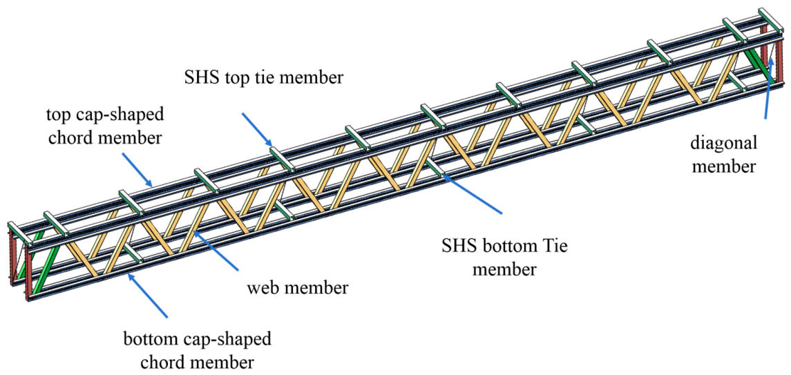
The cap-shaped light-steel trusses consisted of galvanized lipped cap-shaped chord members and square steel tube web members, which were connected using ST5.5 self-tapping screws. Both the top and bottom chords are formed by joining lipped cap-shaped sections with specialized chord splicing connectors. The web members are categorized into three distinct types: Type 1, Type 2, and Type 3, according to the length and position. Full-scale load-bearing tests were conducted on two groups of 18 m span cap-shaped chord light-steel trusses, designated as group I and II, corresponding to chord splice configurations without and with curled edge, respectively. In both specimen groups, the overall depth from the upper surface of the top chord to the lower surface of the bottom chord consisted of 1.388 m. To prevent premature out-of-plane global instability during testing, both truss tests employed a coupled load-carrying system consisting of two parallel trusses. These trusses were interconnected by upper and lower SHS100 × 1.45 square hollow section tubular braces and L50 × 1.5 angle steel diagonal bracings, arranged at a 45-degree angle. The clear spacing between the two trusses was maintained at 1.8 m. The dimensional details and configuration of the test trusses are illustrated in Figure 1 and Figure 2.
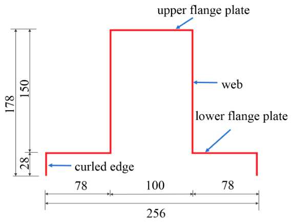
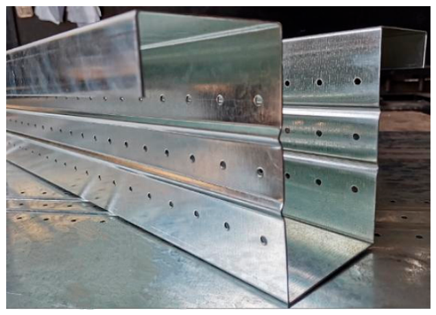
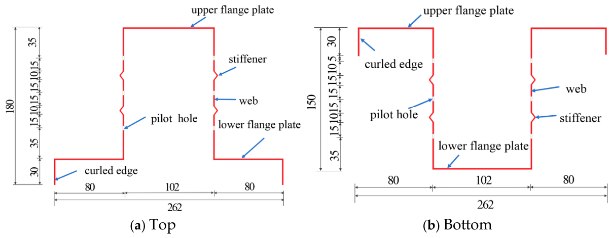
The cap-shaped chord members, as illustrated in Figure 3, were fabricated by cold-forming 1.4 mm thick Q235B galvanized steel plates. The flanges of both the top and bottom chord members are designed with downward-folded lips to facilitate the placement of purlins. In addition, their opening cross-sectional dimensions, as shown in Figure 4, can accommodate the SHS web members.
To facilitate the positioning of self-tapping screws during assembly, three rows of pilot holes are uniformly drilled along both webs of the cap-shaped chord section. These pilot holes have a diameter of 4.5 mm, with a horizontal and vertical spacing of 30 and 40 mm, respectively. In addition, as shown in Figure 4, two longitudinal stiffeners (10 mm in width and 4 mm in depth) were cold-formed on the webs of the chord members, designed to enhance the cross-sectional stiffness and the load-bearing capacity of the chord members. Detailed local dimensions of a cap-shaped chord member segment are provided in Figure 5.
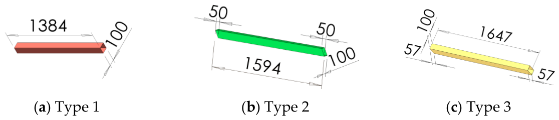
Each truss specimen has a total of 22 SHS web members, which are divided into three types, as shown in Figure 1. The design dimensions of each type of SHS web member are provided in Figure 6.

2.2. Connection Joints

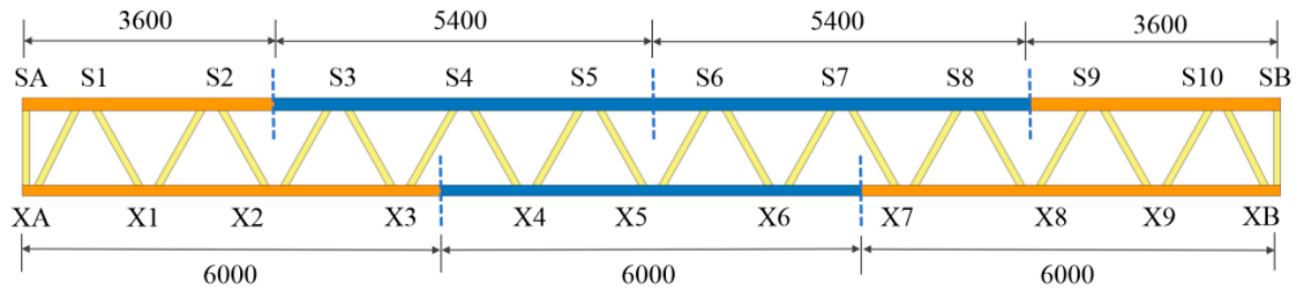
As shown in Figure 7, the top chord consists of two 3600 mm segments (in orange) positioned at the two ends and two 5400 mm segments (in blue) located in the middle portion of the truss. The bottom chord is assembled by connecting three identical cap-shaped members, which are 6000 mm in length. This segmentation strategy can effectively avoid interference between chord splices and the joints connecting the web members. Figure 7 also indicates the joint numbering scheme of the truss specimens, where nodes SA, S1–S10, and SB denote the upper chord joints, while XA, X1–X10, and XB represent the lower chord joints.
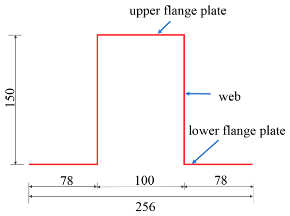
The chord splices were fabricated by cold-forming Q235B thin steel plates, and two different cross-sectional configurations were produced. The main difference between the two types of cross-sections is within the edge (curled or not). The chord splices with and without curled edge were cold formed using 1.4 mm thick steel plates. All chord splices have a uniform length of 400 mm. The detailed cross-sectional configurations and dimensions of the two chord splices are provided in Figure 8 and Figure 9, respectively.
The splicing between segmented chord members and splices, as well as between the chord and web members, were completed using ST 5.5 × 25 self-tapping screws. The quantity and arrangement of the screws are determined based on the internal force calculation results of the members and the structural requirements specified in relevant design codes [47].
The formulas for calculating the shear capacity of a single self-tapping screw are shown in Equations (1) and (2). Based on these formulas, the shear capacity of a single ST5.5 self-tapping screw is calculated to be approximately 4.7 kN.
t 1 t = 1 ,   N v f = 3.7 t 3 d f
t 1 t 2.5 ,   N v f = 2.4 t d f
where N v f is the design value of shear capacity of a single self-tapping screw; d is the diameter of the self-tapping screw; t is the thickness of the thinner steel sheet; t 1 is the thickness of the thicker steel sheet; and f is the design value of the tensile strength of the connected steel sheet.
The number and layout of self-tapping screws at each node of the truss specimen are determined according to the internal forces of the members connected. The number of self-tapping screws at one side for the node between the web and chord members within the 3600 mm range at both ends of the truss specimen is 9 because larger internal forces in the web members are expected in this range. At other nodes, the number of self-tapping screws at one side is 7.
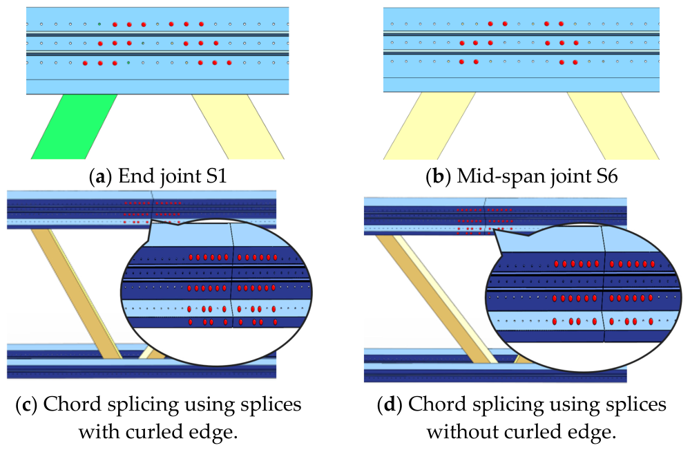
Figure 10a and Figure 10b show the arrangement schemes of self-tapping screws at the upper chord nodes S1 (9 screws at one side) and S6 (7 screws at one side), respectively. Figure 10c and Figure 10d present the arrangement schemes of self-tapping screws at the splicing nodes between the upper chord member segments and the splices with and without curled edge, respectively.

2.3. Material Mechanical Properties

Tensile tests were performed to determine the mechanical properties of the steels, which are provided in Table 1.

3. Testing Program

3.1. Test Setup and Loading Program

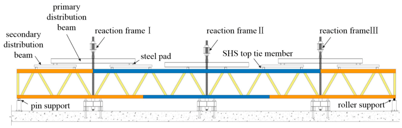
The overall testing setup is illustrated in Figure 11. The two truss specimens were lifted and positioned onto the support piers using chain hoists hung on the reaction frames. To simulate idealized support conditions, square steel tubes and circular rollers were installed on the support piers at the two ends of the trusses, representing the pinned and roller supports, respectively. To simulate the vertical uniform load carried by the truss specimen in engineering practice, concentrated loads were applied to 10 upper chord nodes (S1–S10) using a two-stage loading method.
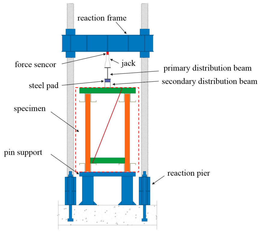
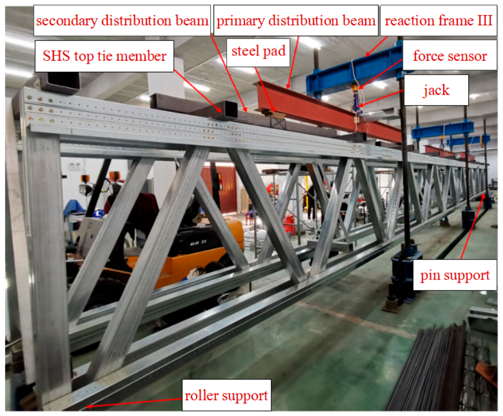
Three reaction frames were set at positions 3600 mm from both ends of the specimen and at the middle position (Figure 11). Concentrated loads were applied to the primary distribution beams via jacks and reaction frames. Steel pads were placed under both ends of the primary distribution beams to transfer the load to the secondary distribution beams, and then the load was transmitted to the upper chord of the specimen via top tie member shown in Figure 2, and the load in the upper chord was subsequently transferred to the lower chord through web members and then to the end supports. In this study, the cumulative load on a single truss is defined as half of the resultant force from the three jacks. This assumption is reasonable for two reasons: First, the two trusses have symmetric geometry and identical boundary conditions. Second, the transverse and diagonal bracing ensures synchronized deformation. This was confirmed by displacement measurements, which showed no significant difference between the two trusses. However, the lateral restraint provided by the adjacent truss and bracing system contributes to the overall stability of each individual truss. Therefore, the reported single truss bearing capacity is applicable only to trusses interconnected with adjacent trusses via transverse and diagonal bracing. For an isolated truss without such lateral restraint, the bearing capacity may be lower, and further experimental investigation is required. Figure 12 illustrates the side view of the loading setup system, while Figure 13 shows the real loading setup.
Before the formal loading process, a preloading, with a magnitude of 20–30% of the estimated ultimate load, was applied to the specimen to check the working status of the data-log and eliminate the effect of potential assembly gaps.
The formal loading process is divided into three stages according to the applied loading magnitude. In stage 1, the loading increment is 10% of the estimated ultimate load until 50% of the estimated ultimate load is reached; in stage 2, when the load is in between 50% and 80% of the estimated ultimate load, the loading increment is reduced to 5% of the estimated ultimate load; in the last stage, when the load exceeds 80% of the estimated ultimate load, the load increment is further reduced to 2% of the estimated ultimate load. If the specimens did not fail when the estimated ultimate load was reached, loading continued with a 2% increment of the estimated ultimate load applied until final failure occurred.

3.2. Deflection Measurement

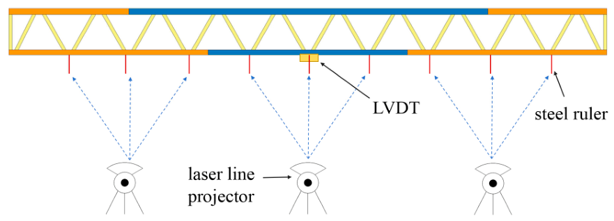
To understand the deformation characteristic of the truss under concentrated loads acting on the nodes of the top chord, vertical displacement of each node of the bottom chord was measured. Steel rulers with an accuracy of 0.5 mm were hung at nodes X1–X9. Manual step-by-step reading was performed with the assistance of a laser spirit-level. Meanwhile, a linear vertical displacement transformer (LVDT) with a sufficient measuring range was installed at the mid-span node (X5) of the truss. Displacement data measured using the LVDT is compared with the steel ruler readings for verification. Figure 14 shows the arrangement of steel rulers and the LVDT.

4. Test Phenomena and Result Analysis

4.1. Failure Mode and Bearing Capacity of Specimens

4.1.1. Group I Truss Specimen

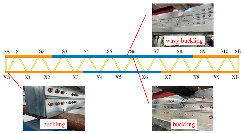
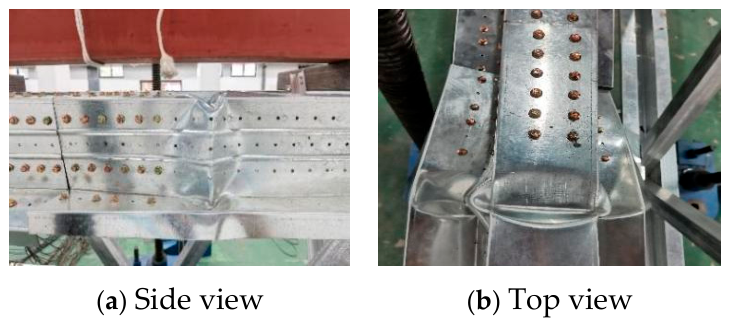
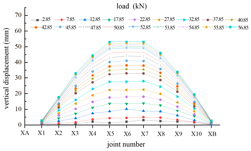
When the cumulative load was less than 52.85 kN, the truss deformation was stable with no buckling phenomenon. When the cumulative load of the truss exceeded 52.85 kN, wavy buckling appeared on the web of the chord between nodes S5 and S6, as shown in Figure 15. As the load further increased to 56.85 kN, significant local buckling occurred on the web of the chord between nodes S5 and S6; meanwhile, local buckling was also observed at the loading point node S6 and the roller support node XA (Figure 15). When the cumulative load reached 57.85 kN, severe buckling failure occurred on the upper chord between nodes S5 and S6, as shown in Figure 16a,b; consequently, the test was terminated. In static load tests, the load level immediately preceding structural failure is taken as the ultimate load, which is defined as the ultimate bearing capacity. The Group I truss specimen was composed of two individual trusses, and the ultimate bearing capacity of a single truss was 56.85 kN, equivalent to 1.05 kN/m2. The maximum load actually sustained by the specimen during the test was 57.85 kN. The corresponding mid-span deflection corresponding to the ultimate load was 53.46 mm, which was 1/337 of the truss specimen span, far below the deflection limit of L/250 (72 mm) [48].

4.1.2. Group II Truss Specimen

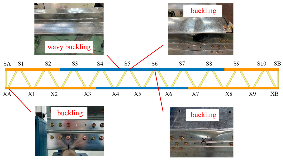
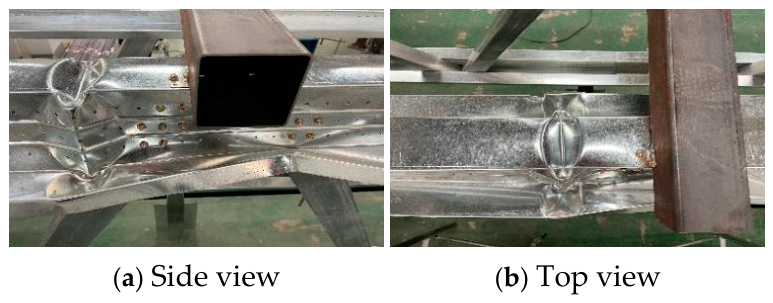
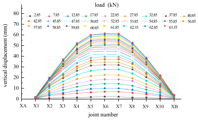
Before the load of the Group II truss specimen reached 50.35 kN, the deformation remained stable. When the load exceeded 50.35 kN, slight buckling occurred at upper chord nodes S4 and S5, and wavy buckling appeared at the web of the upper chord members. As the load of the truss increased to 61.85 kN, severe local buckling of the upper chord member at multiple regions was observed (Figure 17). Near node S4 of the upper chord member, concave deformation occurred at the upper flange, and convex deformation happened at the web; meanwhile, buckling of the chord member occurred at roller support node XA (Figure 17). Buckling deformation also appeared at node S6 (Figure 17). When the load was further increased to 63.85 kN, final failure occurred near node S4 (Figure 18), and the testing was subsequently terminated.
In static load tests, the load level immediately preceding structural failure is taken as the ultimate load, which is defined as the ultimate bearing capacity. The ultimate bearing capacity of the single truss of the Group II specimen was 63.35 kN, equivalent to 1.17 kN/m2. The maximum load actually sustained by the specimen during the test was 63.85 kN. Compared with Group I truss specimen, the ultimate bearing capacity of the Group II truss specimen increased by 11.4%. The corresponding mid-span deflection at the same time was 57.9 mm, which was only 1/311 of the truss specimen span, also far below the deflection limit of L/250 (72 mm) [48]. The results demonstrate that the chord connection method employing edge-curled splicing members enhances the sectional stiffness at the upper chord joint connections, thereby delaying the onset of local buckling and effectively improving the bearing capacity while reducing the deflection of the truss specimens under identical loading conditions.
The failure of both truss specimens originated from the buckling deformation of the mid-span upper chord members or their splices. During the test, no failure occurred at the self-tapping screw connections of each node, and no buckling phenomenon was observed in the web members. This indicates that the insufficient load-bearing capacity of the upper chord members and their splices is the key factor that limits the exertion of the overall load-bearing capacity of the truss specimens.

4.2. Load-Deflection Curve

Through the comparison of load-deflection curves shown in Figure 19 and Figure 20, the deformation characteristics of the two specimens under loading can be observed. Evidently, for both specimens, the mid-span deflection is the maximum, while the deflection at the supports is the minimum. With the gradual increase of the applied load, the deflection of each node exhibits distinct growth rates, and nodes located closer to the mid-span demonstrate a higher deflection growth rate.
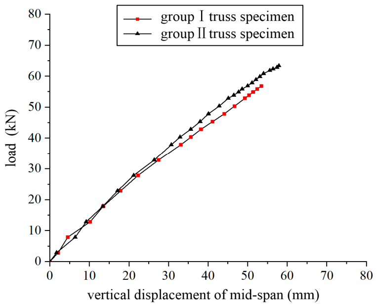
Figure 21 shows the relationship curves between the load and the mid-span deflection for the two groups of truss specimens. It can be observed from the figure that the deflection increases almost linearly with an increase in load. In the initial loading stage, in which the load of a single truss is less than 37.85 kN, the stiffness of the two trusses is similar, and their load-deflection curves nearly overlapped with each other. When the load exceeds 37.85 kN, the load-deflection curves of the two groups separate. The Group II truss specimens have greater flexural stiffness, indicating that the edge-curled design can enhance the stiffness of the truss specimens. The ultimate bearing capacities of the Group I and Group II truss specimens are 56.85 kN and 63.35 kN, respectively, with the former being 89.73% of the latter. This shows that the Group II truss specimen has a higher bearing capacity.
Test results also indicate that the failure mode of both groups of truss specimens is dominated by local buckling of upper chord members and splices under compression at the mid-span, with no plastic zone observed prior to buckling. The edge-curled design can effectively delay the occurrence of local buckling and improve the overall bearing capacity by increasing the local stability of the splices and the upper chord member. In engineering applications, the edge-curled design enhances the stability and bearing capacity of the truss with minor material consumption increment.

5. Finite Element Analysis and Comparison

5.1. Finite Element Model

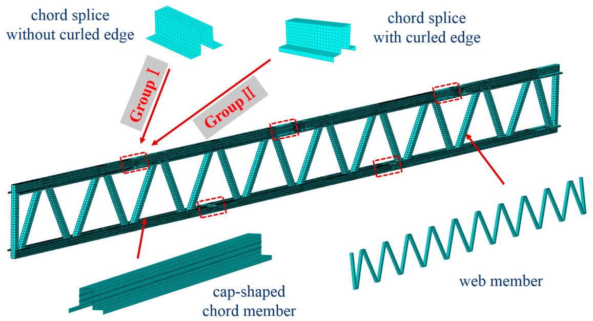
Finite element models of the truss specimens were established using ABAQUS-2020 software. To simplify the calculation, only a single truss of each specimen was built.
The top cap-shaped chord members, square rectangular tube web members, and chord splices of the single truss were created. Since the material thickness of each component is less than 2 mm, shell elements with four nodes were used to simulate each component, which can improve computational efficiency. Finite element models of two different trusses are shown in Figure 22.
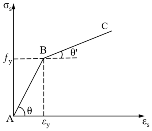
An elastoplastic hardening model was adopted for all steel components of the specimens (as shown in Figure 23: tan θ = E, E is the elastic modulus; tan θ′ = Et, Et is the tangent modulus; fy represents the yield strength; εy represents the yield strain), and their material mechanical properties are detailed in Table 1. The mesh size of the upper chord members, lower chord members, and webs in the truss specimens was 25 mm, while the mesh size of the chord splices was 20 mm.
To simplify the calculation, surface-based tie constraints were used to simulate the connections of self-tapping screws at nodes instead of modelling the self-tapping screws.
To simulate the fixed pin supports and sliding roller supports at both ends of the lower chord of a single truss, the translation of the steel pad at the bottom of the left end of the bottom cap-shaped chord member was constrained in three directions, and the translation of the steel pad at the bottom of the right end was constrained in the lateral and vertical directions. In addition, to avoid out-of-plane instability of the single truss, constraints were applied at the loading positions on the upper surface of the upper chord to forbid its out-of-plane movement.
Finite element analysis of the specimens employed a “static, general procedure” incorporating geometric nonlinearity. Two analysis procedures were defined: linear perturbation buckling analysis and nonlinear analysis based on the arc-length method. Considering the existence of contact interactions, the initial arc-length increment was set to 0.1.
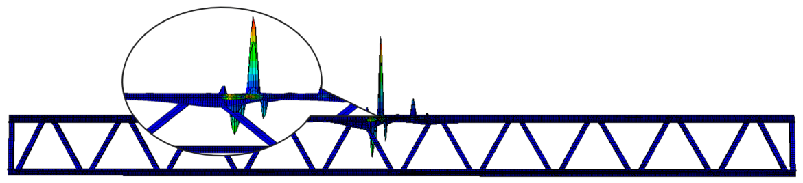
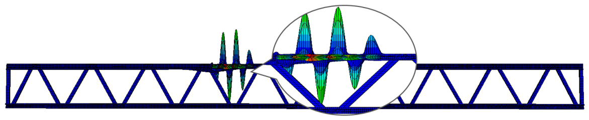
The specific loading process was as follows: first, eigenvalue buckling analysis was performed on the truss specimens, and the buckling modes were compared with the experimental failure modes. It was confirmed that the failure modes of the Group I and II truss specimens were most like the 10th-order and 6th-order buckling modes (Figure 24 and Figure 25), respectively. They were used as the shapes of initial geometric imperfections in the FEA of the two truss specimens. The maximum value of the geometric imperfection was set to be 1/1000 of the total span of the truss, i.e.,18 mm.

5.2. Analysis Results

5.2.1. Comparison of Ultimate Bearing Capacity

According to the characteristics of the arc-length method, after the completion of the FEA, the maximum value of the load proportional factor (LPF) in the corresponding model is taken and then multiplied by the initial load value to obtain the ultimate bearing capacity of the truss specimens.
The comparison of the ultimate bearing capacity between the FEA and the testing results for the two groups of truss specimens is shown in Table 2.
It can be seen from the table that the ratios of the testing result to the FEA result of the ultimate bearing capacity for the two groups of truss specimens are 1.077 and 0.943, respectively, with errors less than 10%. For the Group II truss specimen compared with the Group I truss specimen, the ratio of the FEA results of the ultimate bearing capacity is 1.273, which again indicates that the edge-curled splices can effectively enhance the overall bearing performance of the truss. Although the specific magnitude of improvement (27.3%) differs from the experimental value (11.4%), both the tests and FEA confirm the beneficial effect of the edge-curled splice configuration on the ultimate bearing capacity.
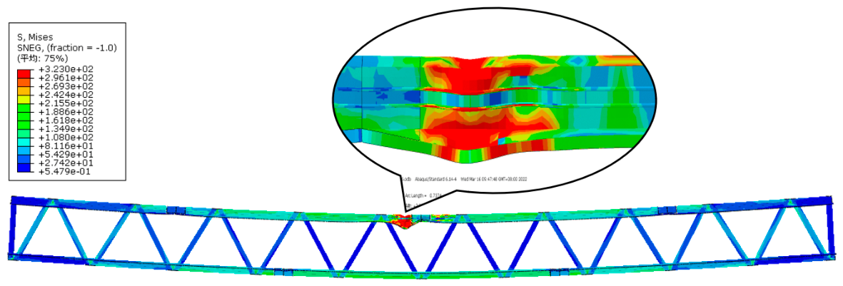
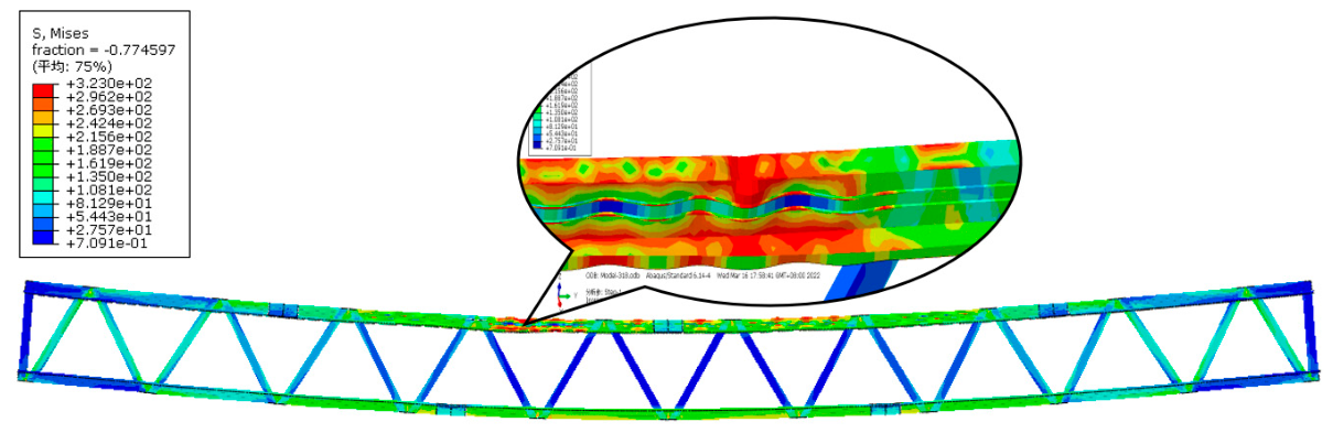
Figure 25 shows the failure location of the Group I truss specimen under the ultimate load obtained by FEA, which is located between upper chord nodes S5 and S6 of the truss, presenting local buckling failure of the non-edge-curled splices. It is consistent with the failure mode obtained in the test, as shown in Figure 16. Similarly, Figure 26 shows the failure location of the Group II truss specimen under the ultimate load, which is between upper chord nodes S4 and S5 of the truss, presenting local buckling failure of the upper chord member, which is also consistent with the failure mode observed in the test, as shown in Figure 18.
The comparison between the FEA and testing results shows that the ultimate bearing capacities and failure modes of the two groups of truss specimens are very close. By introducing initial geometric imperfections with shapes similar to the experimental failure patterns, the finite element model reasonably reproduced the buckling locations and failure modes observed in the tests, thereby supporting the validity of the finite element modeling approach.
To facilitate observing deformation, the overall deformation factor of the Group I truss specimen was magnified by 8 times, and the local deformation factor by 2 times; the overall deformation factor of the Group II truss specimen was magnified by 5 times, and the local deformation factor by 3 times. The stress distribution and deformation of the Group I and II specimens are shown in Figure 26 and Figure 27, respectively.

5.2.2. Comparison of Load-Deflection Curve

Figure 28a and Figure 28b show the comparisons of load-mid-span deflection curves obtained from tests and FEAs for the two groups of truss specimens, respectively. When the load is less than 20 kN and 35 kN for Group I and Group II truss specimens, respectively, the FEA results of the load-deflection curves are in good agreement with the testing results. This indicates that the FEA results can accurately reflect the stiffness characteristics of the specimens. However, when the load of the two groups of truss specimens exceeds the above two values, the FEA curves begin to deviate from the testing results, and the deviation gradually increases with load increases. Moreover, the stiffness obtained from the FEA is greater than the testing value. The main reason is that the self-tapping screw connection between the chord and web members was not directly simulated in the finite element model; instead, a simplified treatment was adopted. Specifically, tie constraints were used to replace the self-tapping screw connection, which could essentially increase the joint stiffness of the truss.

6. Conclusions

In this study, an improved light-steel truss incorporating cap-shaped chord members is proposed and investigated by carrying out full-scale bending tests and FEAs. The ultimate bearing capacity, failure mode, mid-span load-deflection curve, and other characteristics of the light-steel trusses with cap-shaped chord members were studied. The main conclusions are as follows:
(1)
The testing results of the two groups of trusses show that the ultimate bearing capacity of the Group I truss specimen is 56.85 kN, with a mid-span deflection of 53.46 mm; the ultimate bearing capacity of the Group II truss specimen is increased to 63.35 kN, with a mid-span deflection of 57.9 mm. Obviously, the ultimate bearing capacity of Group II is 1.114 times of Group I, but their maximum mid-span deflections are very close.
(2)
The failure mode of the Group I truss specimen is local buckling of the non-edge-curled splices used for connecting the upper chord segments, which leads to the final failure of the truss specimen. The failure mode of the Group II truss specimen is local buckling of the upper chord near the mid-span. Obviously, chord splices with different cross-sectional forms can change the final failure location of the truss specimen, and the overall bearing capacity of the truss depends on the local compressive bearing capacity of the upper chord members and their splices.
(3)
The ratios of the test results to the FEA results of the ultimate bearing capacity of Group I and Group II truss specimens are 1.077 and 0.943, respectively, with a discrepancy of less than 10%. The FEA results of the failure location and failure mode are consistent with the testing observation, which verifies the rationality and correctness of the finite element modeling method proposed in this study for the two groups of truss specimens.

Author Contributions

Investigation, validation, writing—original draft, Y.L.; conceptualization, funding acquisition, investigation, supervision, writing—review and editing, X.W.; methodology, supervision, writing—review and editing, T.L.; writing—original draft, data curation, X.Y.; supervision, X.L. and Q.W. All authors have read and agreed to the published version of the manuscript.

Funding

This research was funded by the Major Science and Technology Program Projects of Hainan Province (grant number ZDKJ2021024), the State Grid Huanggang Power Supply Company 2024 R&D and Application Project for New Types of Prefabricated Cable Bridge Systems (grant number 5215E0240008), and the Huanggang Category II Key Technology Research Project (grant number JGXM20250006). The APC was funded jointly by these three projects.

Data Availability Statement

The original contributions presented in this study are included in the article. Further inquiries can be directed to the corresponding authors.

Conflicts of Interest

The authors declare no conflicts of interest.

References

  1. Reda, M.; Sharaf, T.; ElSabbagh, A.; ElGhandour, M. Behavior and design for component and system of cold-formed steel roof trusses. Thin-Walled Struct. 2019, 135, 21–32. [Google Scholar] [CrossRef]
  2. Bondok, D.; Salim, H.; Urgessa, G. Quasi-static responses and associated failure mechanisms of cold-formed steel roof trusses. Eng. Struct. 2021, 231, 111741. [Google Scholar] [CrossRef]
  3. Dawe, J.; Liu, Y.; Li, J. Strength and behaviour of cold-formed steel offset trusses. J. Constr. Steel Res. 2010, 66, 556–565. [Google Scholar] [CrossRef]
  4. Wang, X.; Wang, J.; Xu, M.; Tang, Y.; Li, D.M.; Wang, Q.; Cai, S.; Hu, S.; Liao, C.; Feng, J. Prefabricated tubular light roof truss assembled with screwed novel modular connectors: Full-scale test and FE modelling. Thin-Walled Struct. 2023, 182, 110229. [Google Scholar] [CrossRef]
  5. Freitas, C.; Yu, C.; Nalla, S. Novel CFS truss with stamped diagonal system. Thin-Walled Struct. 2025, 213, 113295. [Google Scholar] [CrossRef]
  6. Mi, X.; Li, S.; Zhang, Y.; Chen, W.; Huang, X. Experimental investigation and numerical analysis on the stability of curved CFRP thin-walled pipe truss. Compos. Struct. 2023, 321, 117334. [Google Scholar] [CrossRef]
  7. Shi, D.; Xu, Y.; Demartino, C.; Lu, G.; Li, Z. Glubam roof truss with riveted glubam connections adopting thin-walled steel tube: Experiment, modeling, and model-updating. J. Build. Eng. 2024, 96, 110550. [Google Scholar] [CrossRef]
  8. Zaharia, R.; Dubina, D. Stiffness of joints in bolted connected cold-formed steel trusses. J. Constr. Steel Res. 2006, 62, 240–249. [Google Scholar] [CrossRef]
  9. Mathieson, C.; Roy, K.; Charles Clifton, G.; Ahmadi, A.; Lim, J.B.P. Failure mechanism and bearing capacity of cold-formed steel trusses with HRC connectors. Eng. Struct. 2019, 201, 109741. [Google Scholar] [CrossRef]
  10. Mathison, C.; Roy, K.; Clifton, G.; Ahmadi, A.; Masood, R.; Lim, J.B.P. Novel pin jointed moment connection for cold-formed steel trusses. Steel Compos. Struct. 2019, 31, 453–467. [Google Scholar] [CrossRef]
  11. Pedreschi, R.; Sinha, B. An experimental study of cold formed steel trusses using mechanical clinching. Constr. Build. Mater. 2008, 22, 921–931. [Google Scholar] [CrossRef]
  12. Ungureanu, V.; Both, I.; Burca, M.; Radu, B.; Neagu, C.; Dubina, D. Experimental and numerical investigations on built-up cold-formed steel beams using resistance spot welding. Thin-Walled Struct. 2021, 161, 107456. [Google Scholar] [CrossRef]
  13. Taranu, G.; Toma, I. Experimental Investigation and Numerical Simulation of C-Shape Thin-Walled Steel Profile Joints. Buildings 2021, 11, 636. [Google Scholar] [CrossRef]
  14. Elsawi Mahmoud, M.; El-Sisi, A.; Elbelbisi, A.; Elemam, H.; Salim, H. Performance of CFS trusses self-drilling screws connections under extreme loads. Structures 2025, 74, 108592. [Google Scholar] [CrossRef]
  15. Li, H.; Shi, Y.; Xiang, Y.; Ran, X. Shear behavior of screw connections: Experiment, analysis, and application in CFS trusses. Structures 2025, 73, 108405. [Google Scholar] [CrossRef]
  16. Rezaeian, H.; Roy, K.; Yekrangnia, M.; Chen, B.; Lim, J. Tests, numerical modelling and design of a novel cold-formed steel Tab connection. J. Constr. Steel Res. 2021, 185, 106846. [Google Scholar] [CrossRef]
  17. Wang, X.; Yuan, X.; Zeng, H.; Li, T.; Liang, Y.; Gao, X.; Yu, Y. Bearing Capacity and Failure Mode of a Light-Steel Tubular K-joint Connected by a Novel U-shape Connector. Appl. Sci. 2021, 11, 8587. [Google Scholar] [CrossRef]
  18. Lukačević, L.; Krolo, P.; Bakran, A.; Palijan, I. Shear Behaviour of Novel U-connector in CFS Truss-to-Column Connection. Ce/Papers 2023, 6, 1995–2000. [Google Scholar] [CrossRef]
  19. Yang, Y.; Liao, F.; Ren, Y.; Zhou, J.; Wang, Y. Hysteretic behavior of concrete filled thin-walled steel tubular K-joints with spherical-cap gap at chord. Thin-Walled Struct. 2025, 213, 113303. [Google Scholar] [CrossRef]
  20. Dizdar, Ç.; Baran, E.; Topkaya, C. Strength and stiffness of floor trusses fabricated from cold-formed steel lipped channels. Eng. Struct. 2019, 181, 437–457. [Google Scholar] [CrossRef]
  21. Gordziej-Zagórowska, M.; Urbańska-Galewska, E.; Deniziak, P. Experimental investigation of joint with positive eccentricity in CFS truss. Thin-Walled Struct. 2020, 157, 106998. [Google Scholar] [CrossRef]
  22. Gordziej-Zagórowska, M.; Urbańska-Galewska, E.; Deniziak, P. Analysis of Failure Mechanism in Joints with Positive Eccentricity in CFS Truss. Materials 2021, 14, 6986. [Google Scholar] [CrossRef]
  23. Wang, W.; Roy, K.; Rezaeian, H.; Lim, J. Structural behavior of cold-formed steel trusses incorporating built-up section chords. Thin-Walled Struct. 2026, 218, 114054. [Google Scholar] [CrossRef]
  24. Li, H.; Young, B. Design of cold-formed high strength steel tubular sections undergoing web crippling. Thin-Walled Struct. 2018, 133, 192–205. [Google Scholar] [CrossRef]
  25. Cruise, R.; Gardner, L. Strength enhancements induced during cold forming of stainless steel sections. J. Constr. Steel Res. 2008, 64, 1310–1316. [Google Scholar] [CrossRef]
  26. Li, L.; Li, H.; Young, B. Cold-formed ferritic stainless steel SHS and RHS beams: Testing, modeling and design. J. Constr. Steel Res. 2022, 197, 107429. [Google Scholar] [CrossRef]
  27. Fang, Z.; Roy, K.; Chi, Y.; Chen, B.; Lim, J. Finite element analysis and proposed design rules for cold-formed stainless steel channels with web holes under end-one-flange loading. Structures 2021, 34, 2876–2899. [Google Scholar] [CrossRef]
  28. Dai, Y.; Roy, K.; Fang, Z.; Chen, B.; Raftery, G.; Lim, J. A novel machine learning model to predict the moment capacity of cold-formed steel channel beams with edge-stiffened and un-stiffened web holes. J. Build. Eng. 2022, 53, 104592. [Google Scholar] [CrossRef]
  29. Fang, Z.; Roy, K.; Mares, J.; Sham, C.; Chen, B.; Lim, J. Deep learning-based axial capacity prediction for cold-formed steel channel sections using Deep Belief Network. Structures 2021, 33, 2792–2802. [Google Scholar] [CrossRef]
  30. Ma, Y.; Liu, Y.; Ma, T.; Zafimandimby, M. Flexural Stiffness of Rectangular Hollow Section (RHS) Trusses. Eng. Struct. 2021, 239, 112336. [Google Scholar] [CrossRef]
  31. Sun, H.; He, Z.; Zhao, J. Investigation of internal forces of a truss structure. Structures 2025, 71, 107891. [Google Scholar] [CrossRef]
  32. Jiang, C.; Tang, C.; Seidel, H.; Chen, R.; Wonka, P. Computational Design of Lightweight Trusses. Comput.-Aided Des. 2021, 141, 103076. [Google Scholar] [CrossRef]
  33. Wang, W.; Roy, K.; Rezaeian, H.; Fang, Z.; Lim, J. Moment capacity of cold-formed steel trusses with Howick Rivet Connectors: Tests, modelling and design. Eng. Struct. 2025, 322, 119171. [Google Scholar] [CrossRef]
  34. Song, L.; Yan, W.; Yu, C.; Xie, Z.; Tan, Q. Flexural behavior investigation of the CFS truss beams with self-piercing riveted connection. J. Constr. Steel Res. 2019, 156, 28–45. [Google Scholar] [CrossRef]
  35. Chen, B.; Roy, K.; Uzzaman, A.; Raftery, G.; Nash, D.; Clifton, G.; Pouladi, P.; Lim, J. Effects of edge-stiffened web openings on the behaviour of cold-formed steel channel sections under compression. Thin-Walled Struct. 2019, 144, 106307. [Google Scholar] [CrossRef]
  36. Chen, B.; Roy, K.; Uzzaman, A.; Raftery, G.; Lim, J. Axial strength of back-to-back cold-formed steel channels with edge-stiffened holes, un-stiffened holes and plain webs. J. Constr. Steel Res. 2020, 174, 106313. [Google Scholar] [CrossRef]
  37. Chen, B.; Roy, K.; Uzzaman, A.; Raftery, G.; Lim, J. Parametric study and simplified design equations for cold-formed steel channels with edge-stiffened holes under axial compression. J. Constr. Steel Res. 2020, 172, 106161. [Google Scholar] [CrossRef]
  38. Chen, B.; Roy, K.; Fang, Z.; Uzzaman, A.; Raftery, G.; Lim, J. Moment capacity of back-to-back cold-formed steel channels with edge-stiffened holes, un-stiffened holes, and plain webs. Eng. Struct. 2021, 235, 112042. [Google Scholar] [CrossRef]
  39. Roy, K.; Lau, H.; Ting, T.; Chen, B.; Lim, J. Flexural capacity of gapped built-up cold-formed steel channel sections including web stiffeners. J. Constr. Steel Res. 2020, 172, 106154. [Google Scholar] [CrossRef]
  40. Chen, B.; Dai, Y.; Wang, W.; Wang, Y.; Luo, L.; Dai, P.; Lim, J. An experimental study on web-bearing resistance of cold-formed steel sigma-shaped sections with web holes under interior-two-flange loading case. Thin-Walled Struct. 2024, 205, 112579. [Google Scholar] [CrossRef]
  41. Chen, B.; Wang, Y.; Wang, Y.; Luo, L.; Li, B.; Lim, J.; Dai, Y. New design recommendations for QN1803 high-strength stainless-steel plate girders with web openings in shear. J. Constr. Steel Res. 2024, 221, 108907. [Google Scholar] [CrossRef]
  42. Zhu, L.; Jiang, Y.; Liu, Z.; Wang, Y.; Wang, W.; Chen, B. Web crippling behaviour of high-strength aluminium alloy channel-shaped members with strengthened web holes: Numerical study and new design rules. Structures 2024, 65, 106690. [Google Scholar] [CrossRef]
  43. Zhao, J.; Liu, S.; Chen, B. Axial strength of slotted perforated cold-formed steel channels under pinned-pinned boundary conditions. J. Constr. Steel Res. 2023, 200, 107673. [Google Scholar] [CrossRef]
  44. Yuan, J.; Li, H.T.; Zhang, X. Experimental investigation on cold-formed stainless steel stiffened C-sections under localized interior-two-flange loading. J. Constr. Steel Res. 2024, 223, 108986. [Google Scholar] [CrossRef]
  45. Hou, Y.; Li, Z.; Ni, S.; Gong, J. Structural responses of a modular thin-walled steel trestle structure. J. Constr. Steel Res. 2019, 158, 502–521. [Google Scholar] [CrossRef]
  46. Zou, Y.; Zhou, X.; Shi, Y.; Wang, Z.; Ke, K.; Zhang, Z.; Guan, Y. Shear resistance of cold-formed thin-walled steel inter-story connections. J. Constr. Steel Res. 2021, 183, 106757. [Google Scholar] [CrossRef]
  47. GB50018-2002; Technical Code of Cold-Formed Thin-Wall Structures. Ministry of Construction of the People’s Republic of China: Beijing, China; General Administration of Quality Supervision, Inspection and Quarantine of the People’s Republic of China: Beijing, China, 2002.
  48. GB50017-2017; Standard for Design of Steel Structures. Ministry of Construction of the People’s Republic of China: Beijing, China; Inspection and Quarantine of the People’s Republic of China: Beijing, China, 2017.
Figure 1. Single light-steel truss with cap-shaped chords.
Buildings 16 02147 g001
Figure 2. Schematic diagram of the two-truss specimen assembly.
Buildings 16 02147 g002
Figure 3. The cap-shaped chord member.
Buildings 16 02147 g003
Figure 4. Cross-sectional dimensions of the cap-shaped chord members.
Buildings 16 02147 g004
Figure 5. Local dimensions of the cap-shaped chord member.
Buildings 16 02147 g005
Figure 6. Dimensions of three types of SHS web members.
Buildings 16 02147 g006
Figure 7. Overall segmentation diagram of the truss specimens.
Buildings 16 02147 g007
Figure 8. Cross-sectional dimension of the chord splice without curled edge.
Buildings 16 02147 g008
Figure 9. Cross-sectional dimension of the chord splice with curled edge.
Buildings 16 02147 g009
Figure 10. Arrangement of self-tapping screws in truss joints.
Buildings 16 02147 g010
Figure 11. Front view of the testing setup.
Buildings 16 02147 g011
Figure 12. Side view of loading setup.
Buildings 16 02147 g012
Figure 13. Real loading setup.
Buildings 16 02147 g013
Figure 14. Vertical displacement measurement of each bottom chord node.
Buildings 16 02147 g014
Figure 15. Failure mode of Group I truss specimen.
Buildings 16 02147 g015
Figure 16. Local buckling failure of upper chord between S5 and S6.
Buildings 16 02147 g016
Figure 17. Failure mode of Group II truss specimen.
Buildings 16 02147 g017
Figure 18. Local buckling failure of upper chord segment between S4 and S5.
Buildings 16 02147 g018
Figure 19. The load-deflection curves of Group I truss specimen.
Buildings 16 02147 g019
Figure 20. The load-deflection curves of Group II truss specimen.
Buildings 16 02147 g020
Figure 21. Mid-span load-deflection curves of single truss of two specimens.
Buildings 16 02147 g021
Figure 22. Finite element model of truss specimens.
Buildings 16 02147 g022
Figure 23. Elastoplastic hardening model.
Buildings 16 02147 g023
Figure 24. The 10th-order buckling mode shape.
Buildings 16 02147 g024
Figure 25. The 6th-order buckling mode shape.
Buildings 16 02147 g025
Figure 26. Stress distribution and deformation of Group I truss specimen.
Buildings 16 02147 g026
Figure 27. Stress distribution and deformation of Group II truss specimen.
Buildings 16 02147 g027
Figure 28. Comparison of load-deflection curves for two groups of truss specimens.
Buildings 16 02147 g028
Table 1. Test results of mechanical properties of member Materials.
Specimen
Name
Thickness
(mm)
Yield
Strength
(MPa)
Elastic
Modulus
(MPa)
Tensile
Strength
(MPa)
Elongation
(%)
Chord member & splice without curled edge1.40323185,30138915.6
web member1.45371184,44145211.0
Splice with curled edge1.40306169,80939716.4
Note: All values in the table are the average of 6 coupon specimens.
Table 2. Comparison of ultimate bearing capacity for two groups of truss specimens.
Specimen NameTesting Result
Ft (kN)
FEA Result
Ff (kN)
F t / F f
Group I56.8552.801.077
Group II63.3567.200.943
Disclaimer/Publisher’s Note: The statements, opinions and data contained in all publications are solely those of the individual author(s) and contributor(s) and not of MDPI and/or the editor(s). MDPI and/or the editor(s) disclaim responsibility for any injury to people or property resulting from any ideas, methods, instructions or products referred to in the content.