Calculation Method for Torsional Moment of Inertia of Half-Through Truss Bridges


Abstract
1. Introduction
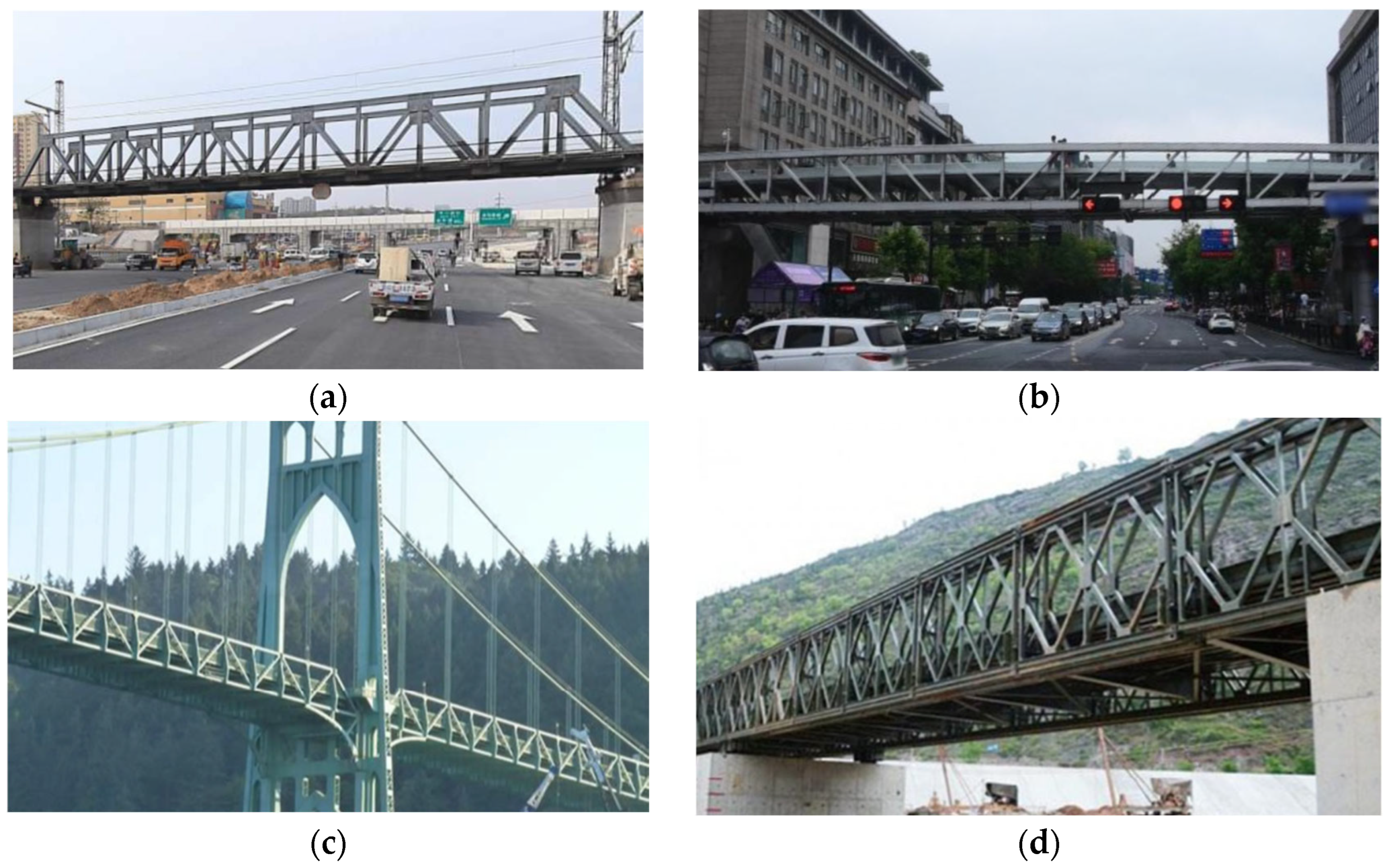
1.1. Review of Torsional Stiffness Analysis for Half-Through Truss Bridges
1.2. Brief Introduction to Existing Methods
2. Modified Equation of Free Torsional Moment of Inertia
2.1. Limitations of the Existing Formulation
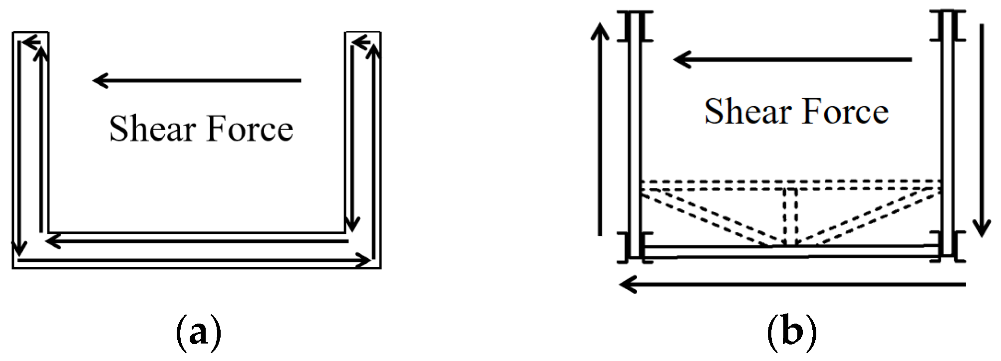
2.1.1. The Limitation of Closed Shear Flow
2.1.2. The Limitation of Rigid Cross-Section Assumption
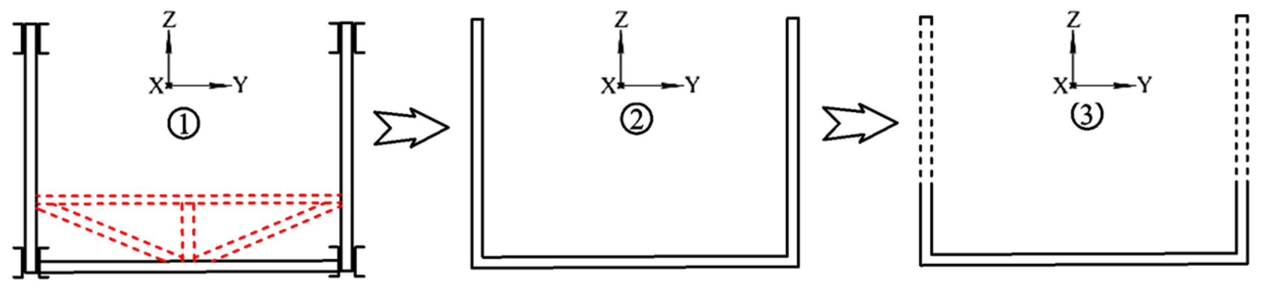
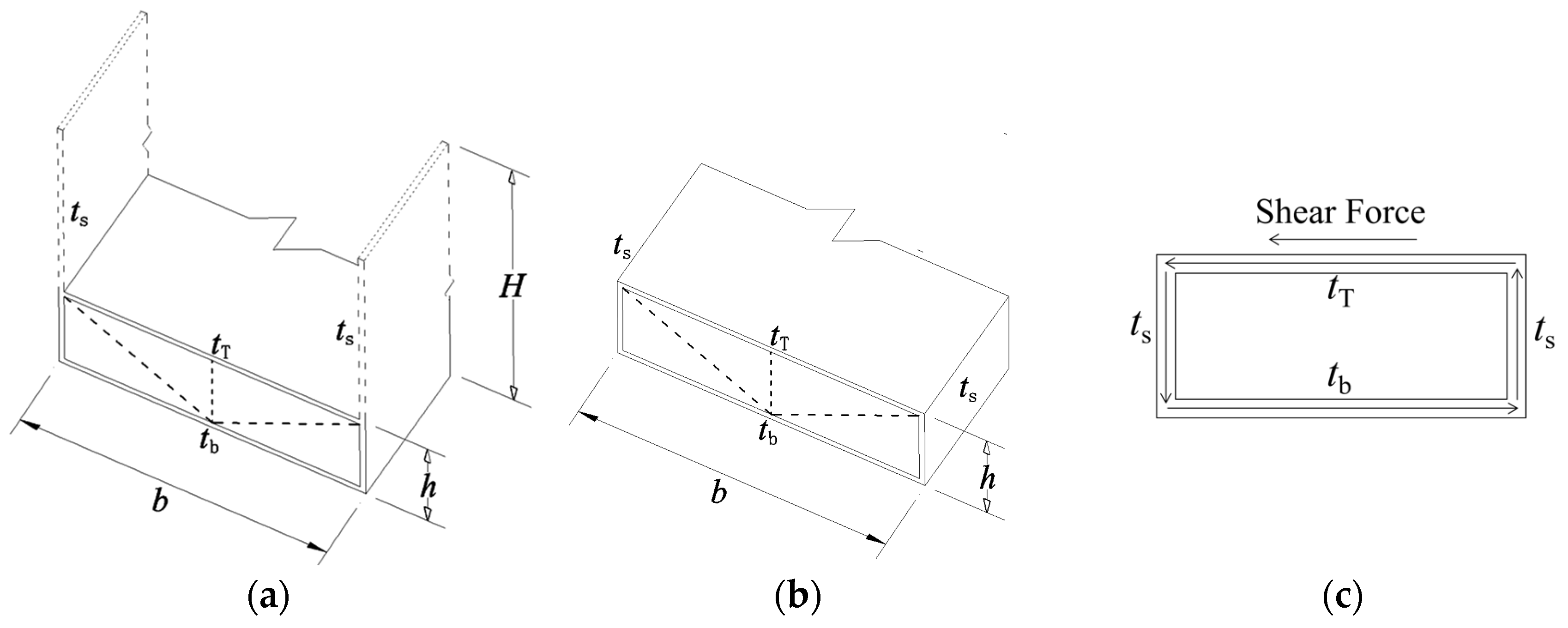
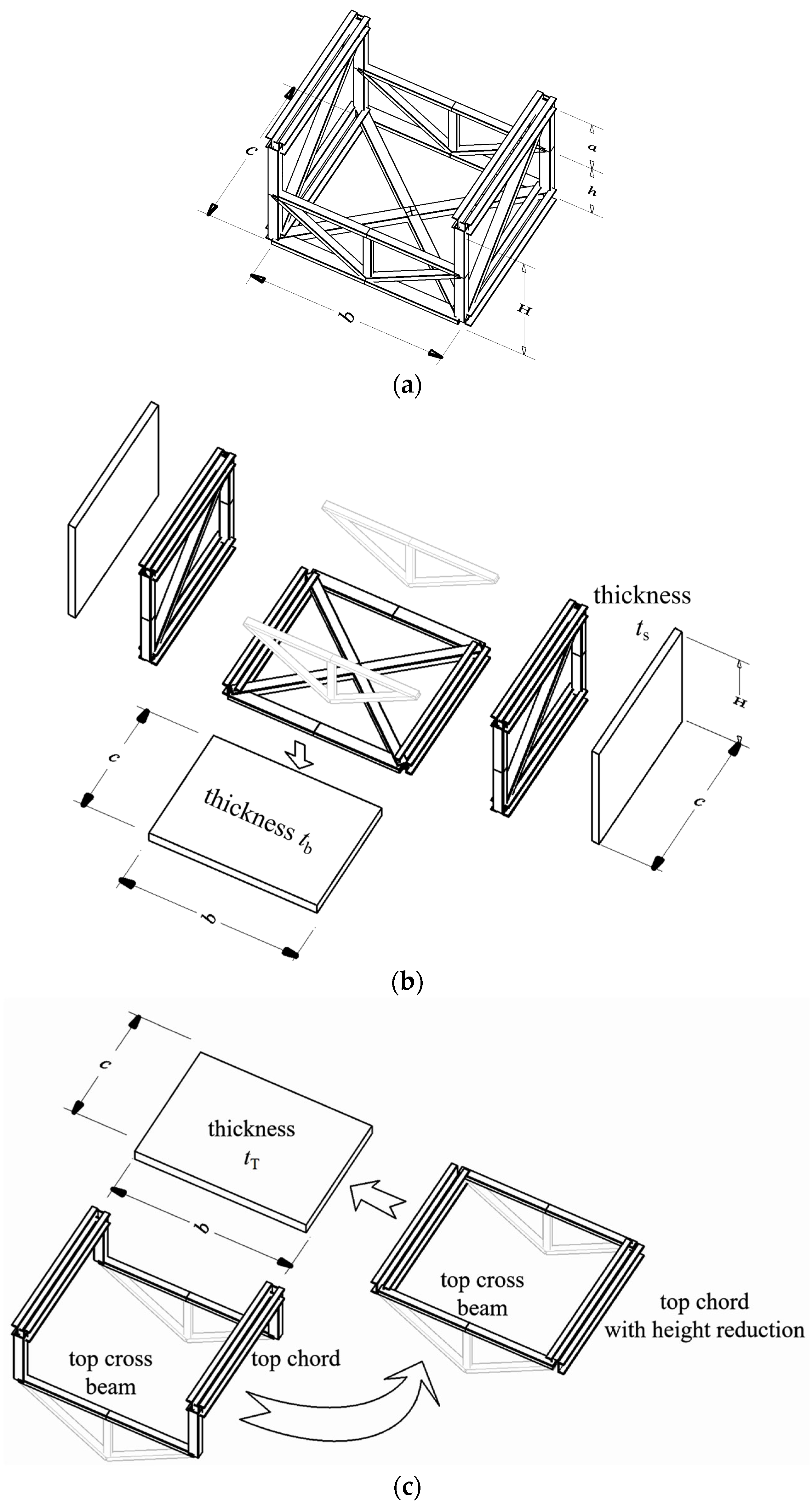
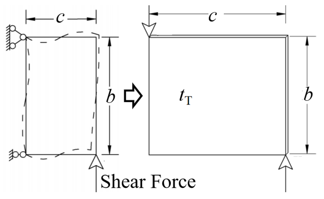
2.2. Equivalent Closed Cross-Section
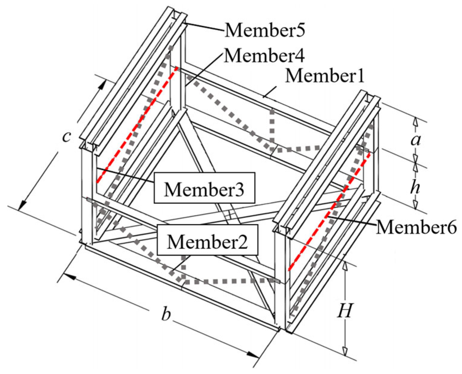
2.3. Member Number and Basic Specifications
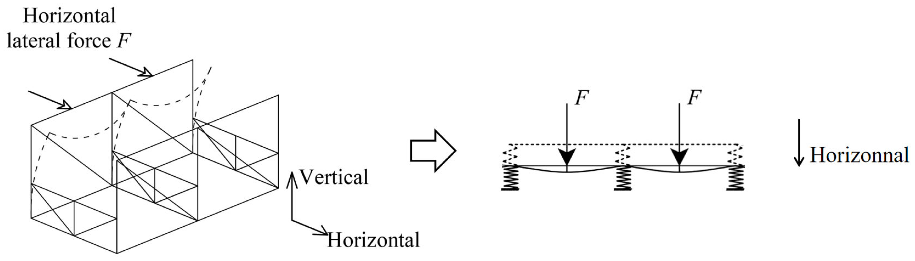
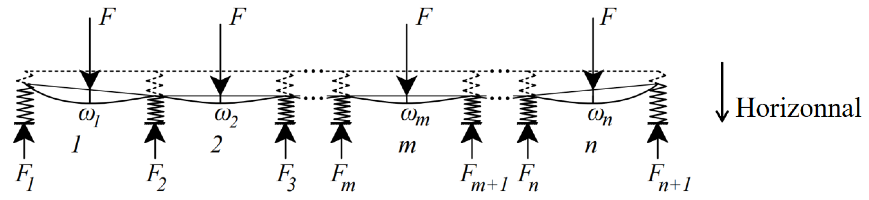
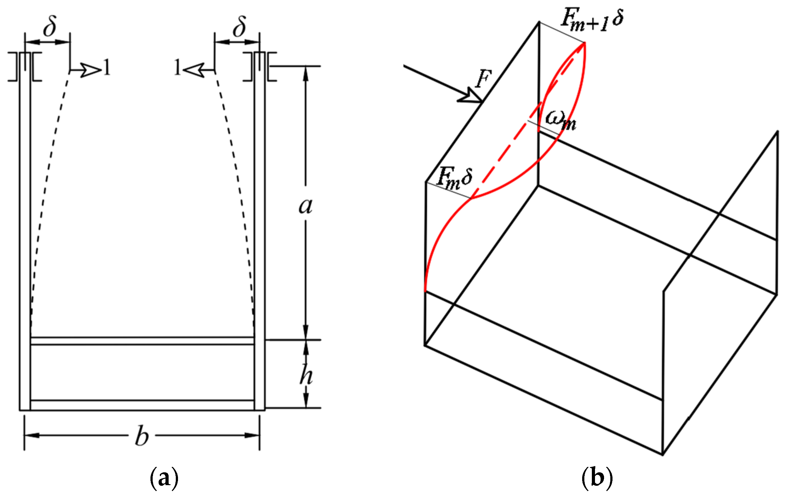
2.4. Equivalent Reduction in the Moment of Inertia of the Top Chord
3. Modification of the Combined Torsional Moment of Inertia
3.1. The Combined Torsional Moment of Inertia
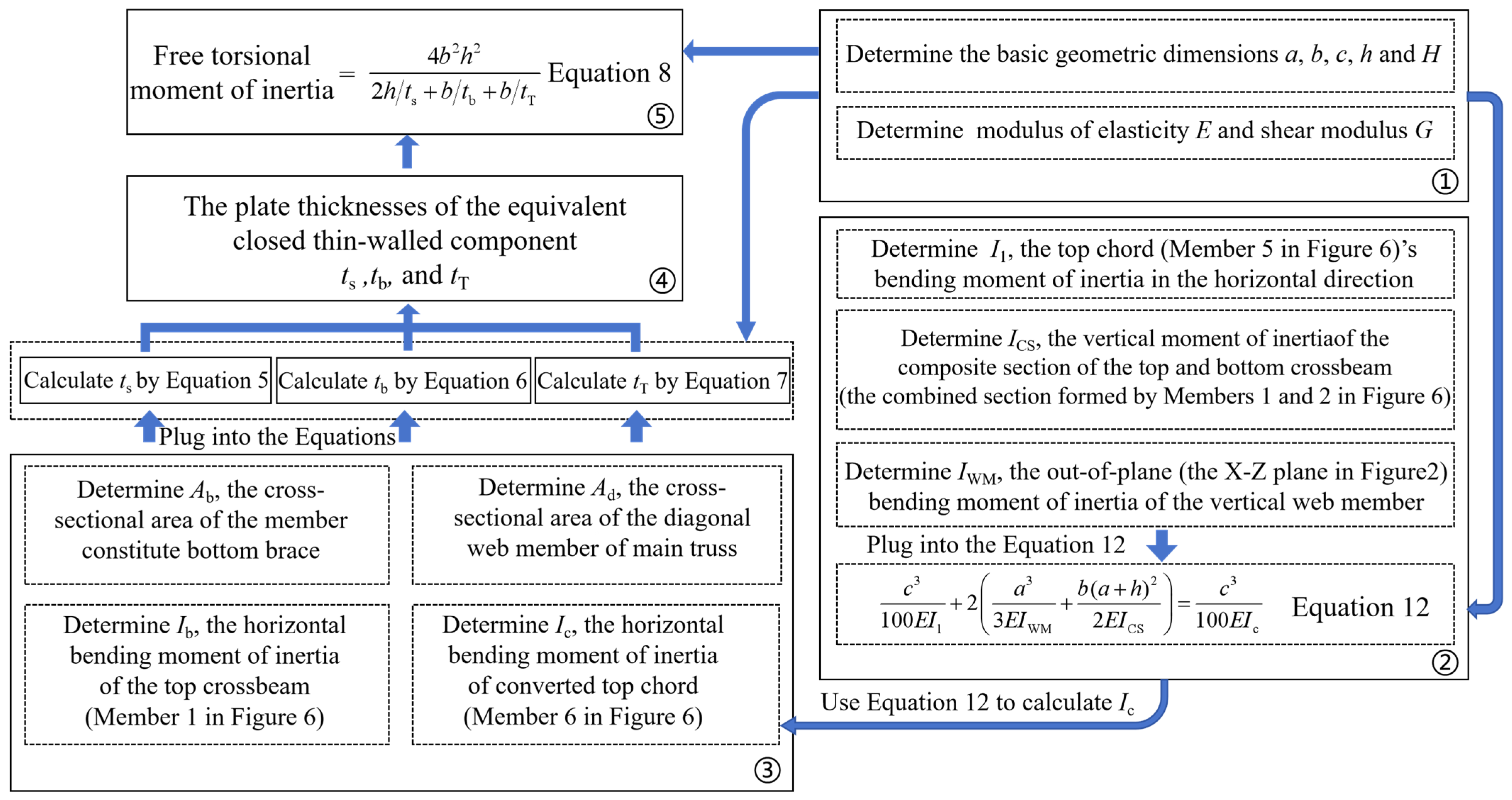
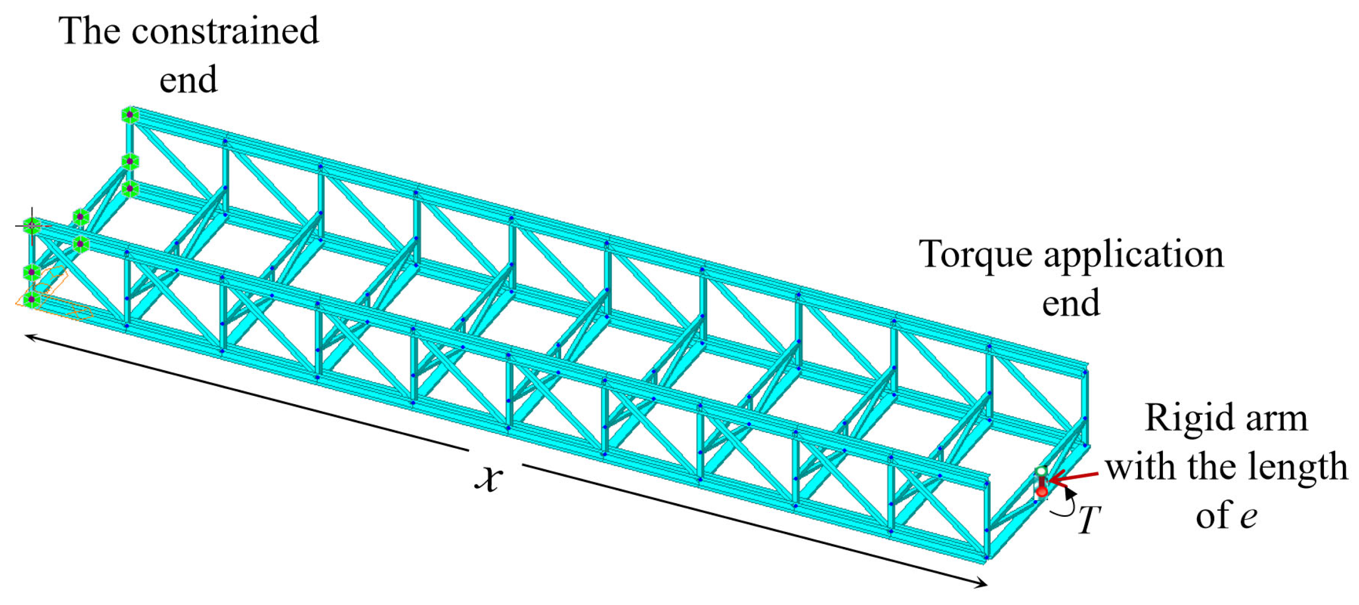
3.2. Description of Calculation Procedure of Free Torsional Moment of Inertia
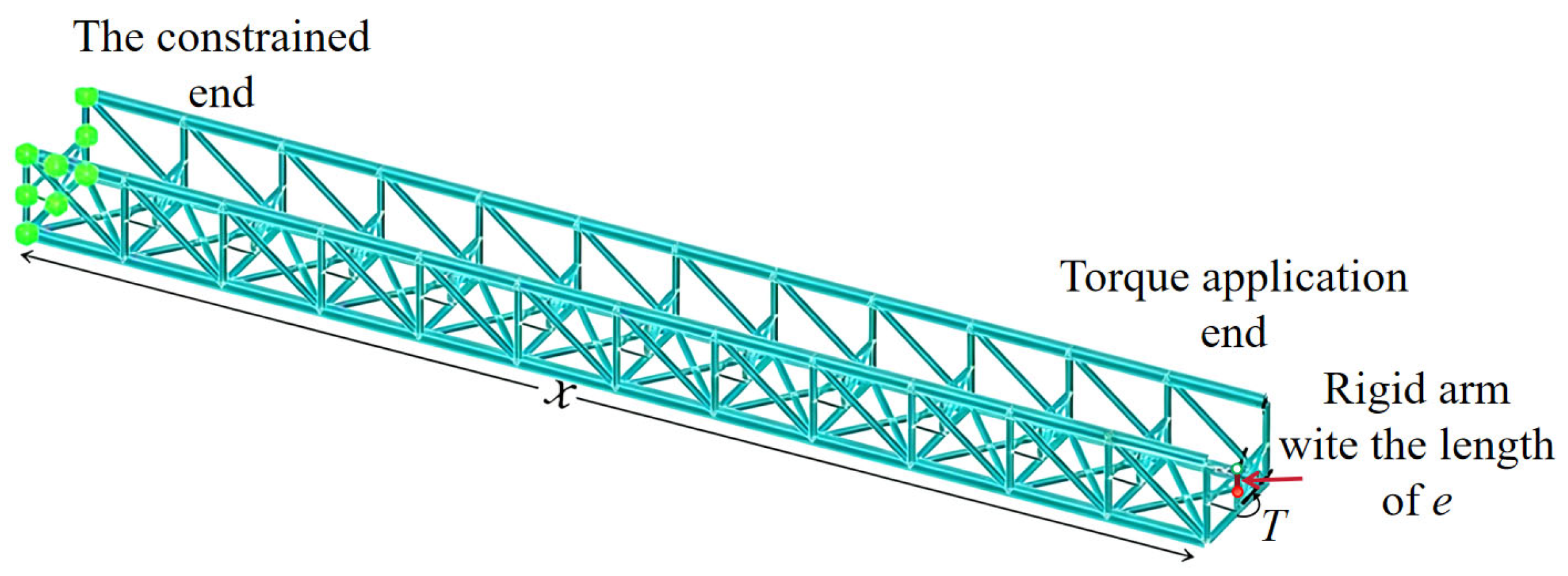
3.3. Bridge Case and Computational Model
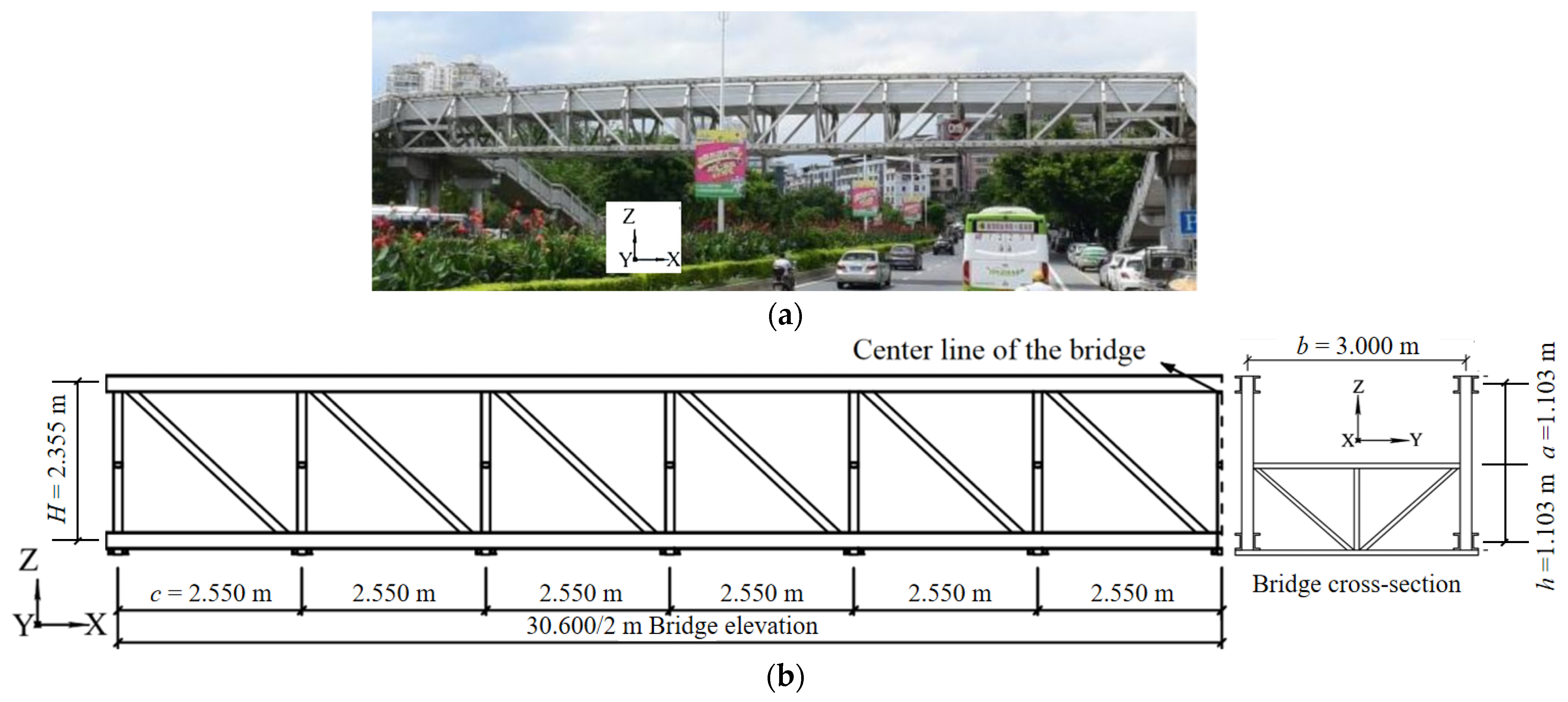
3.3.1. Case 1 and the Corresponding Computational Model
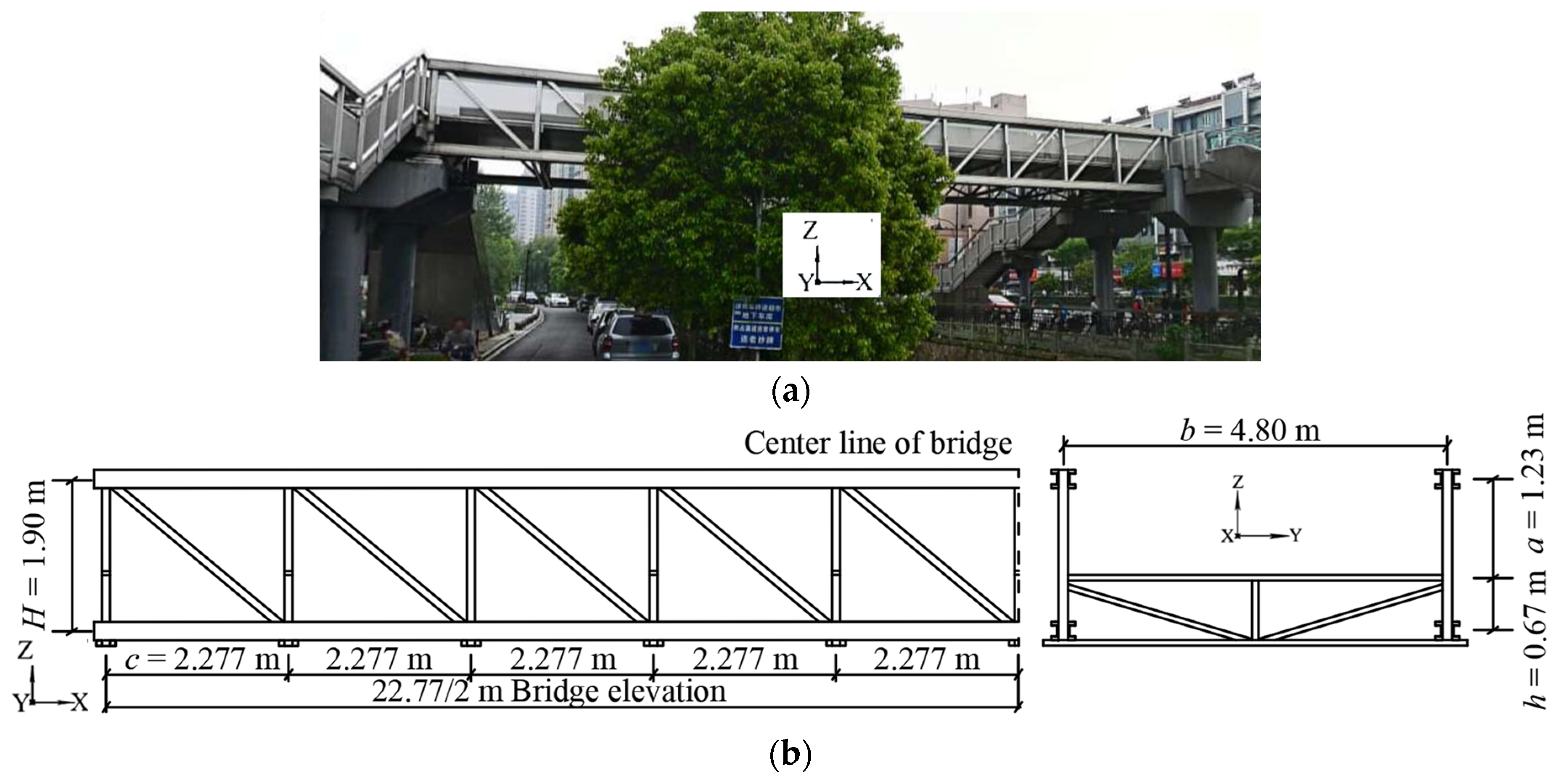
3.3.2. Case 2 and the Corresponding Computational Model
3.4. Validation
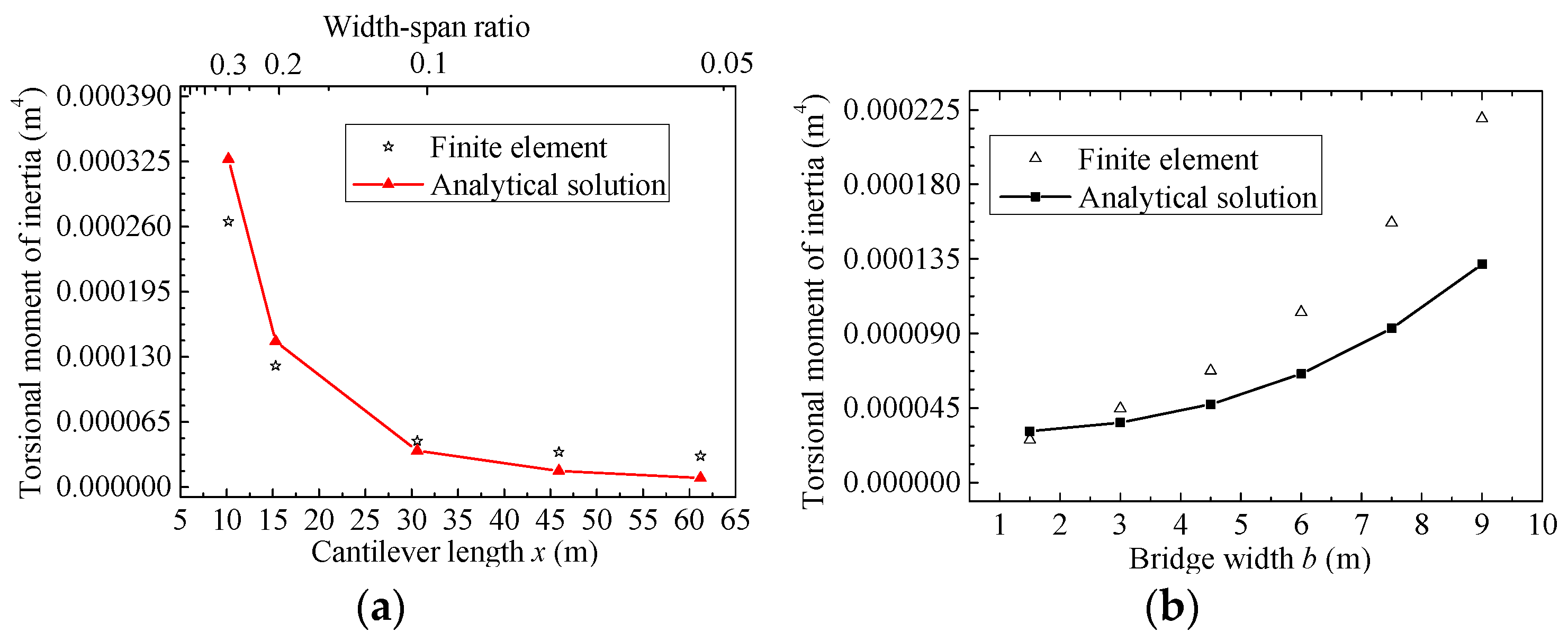
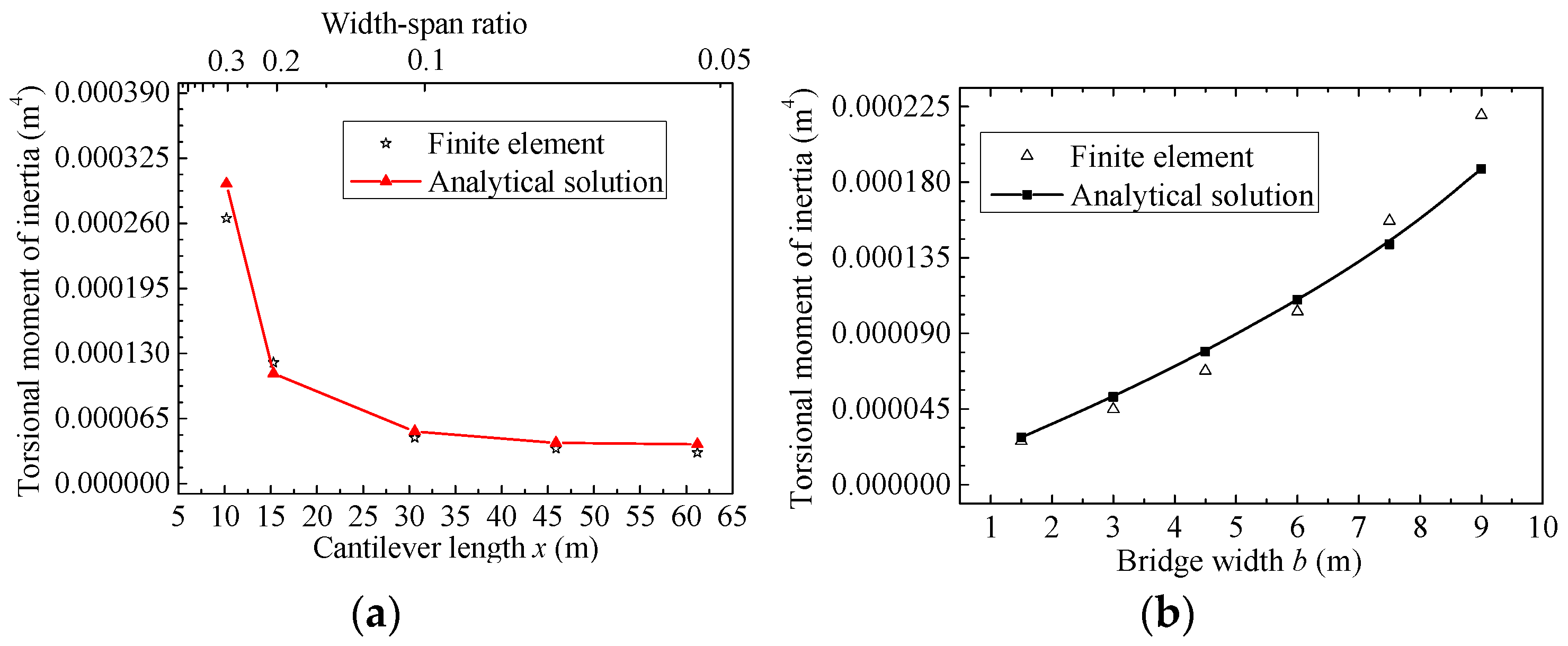
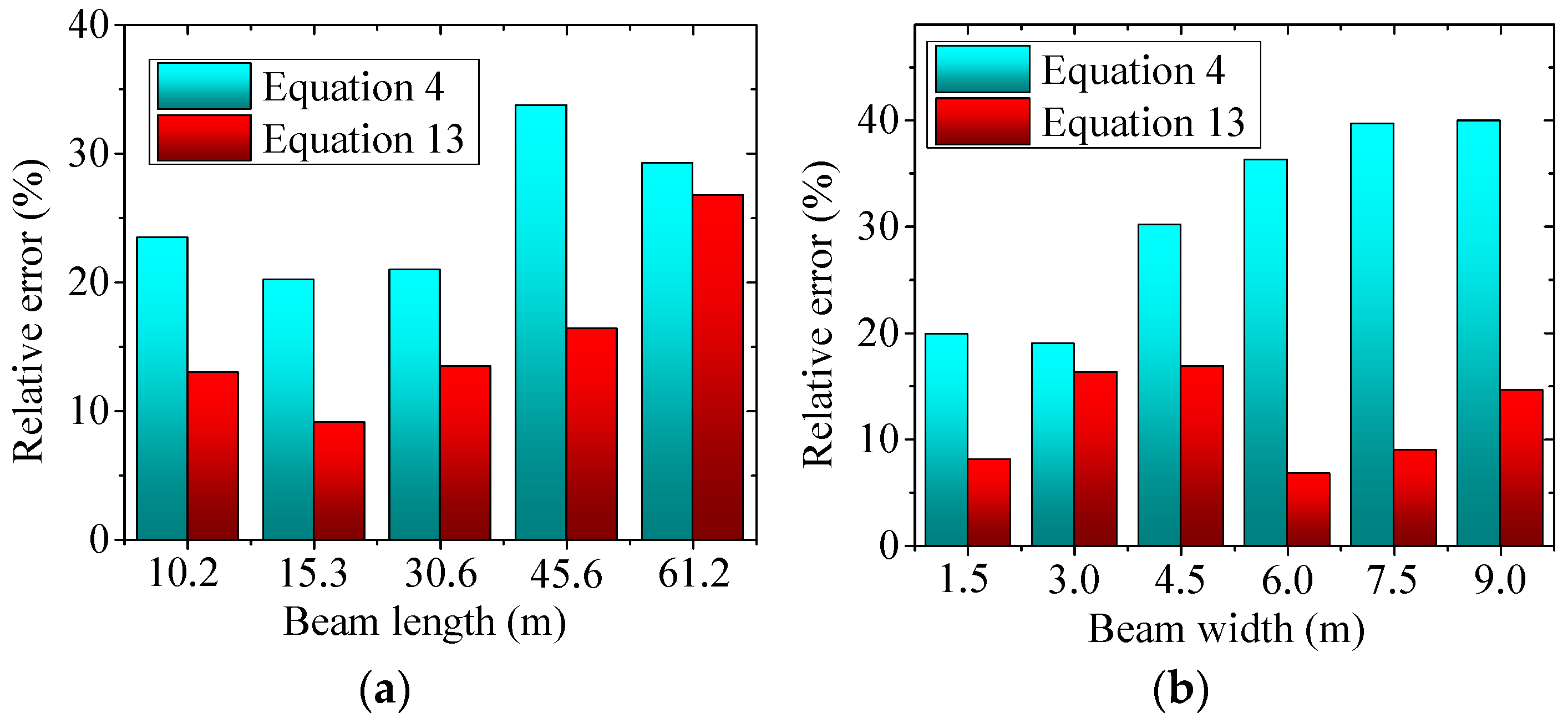
3.4.1. Validation by Case 1
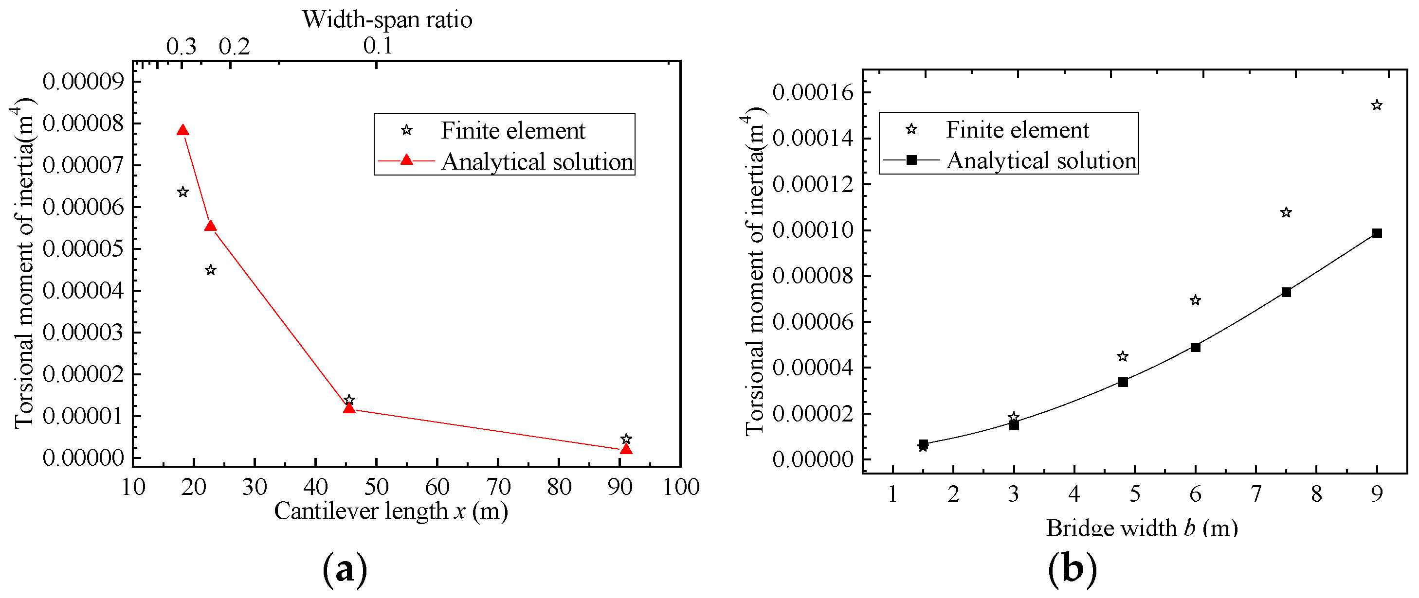
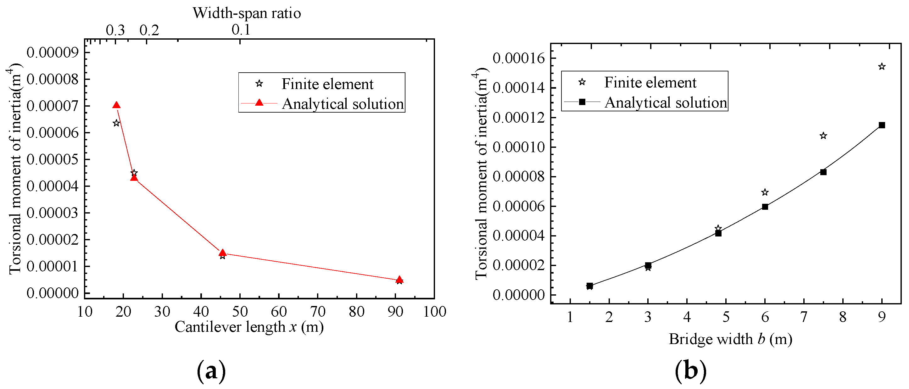
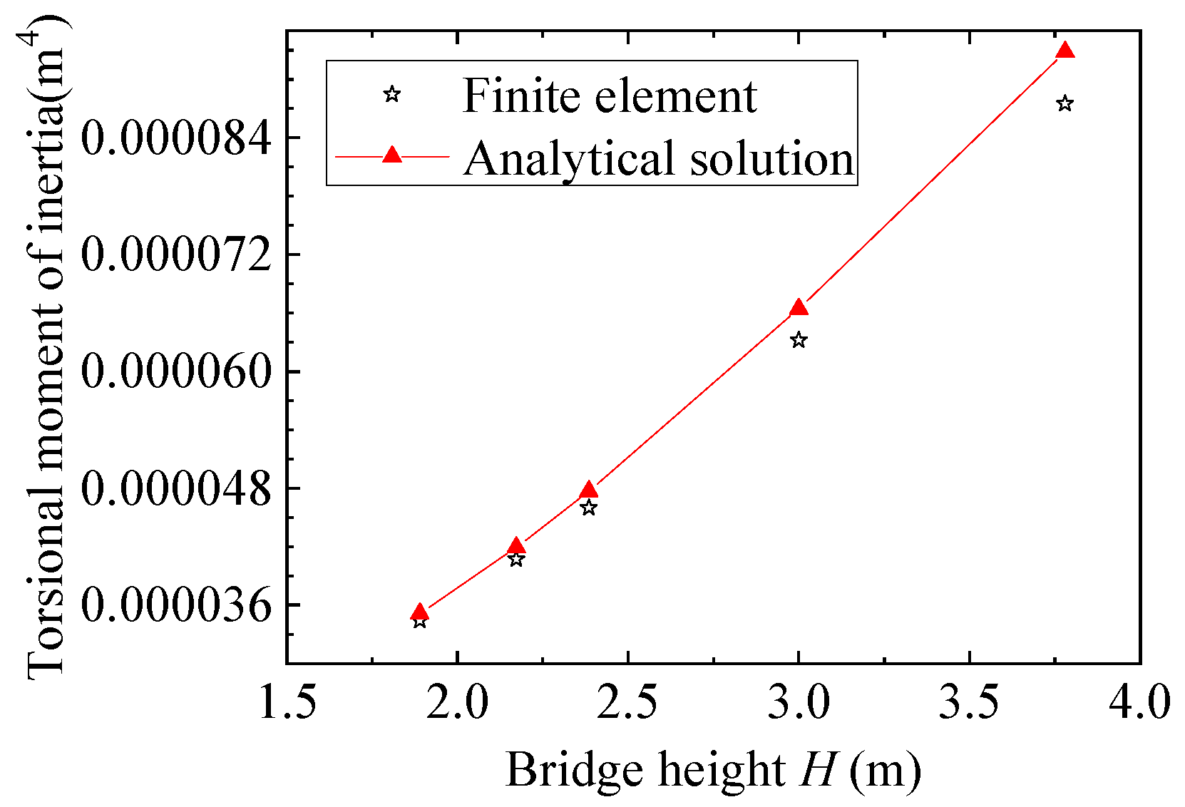
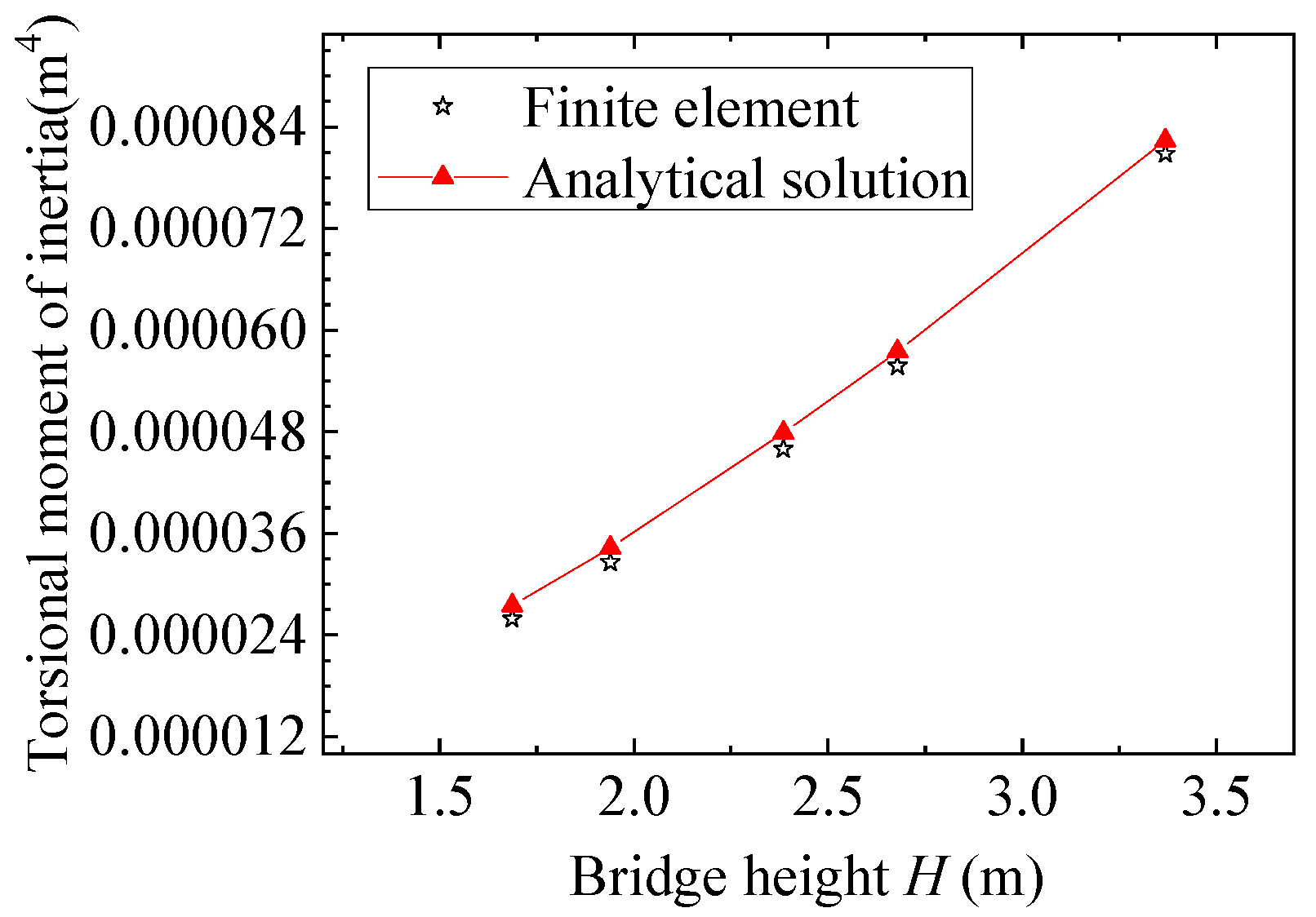
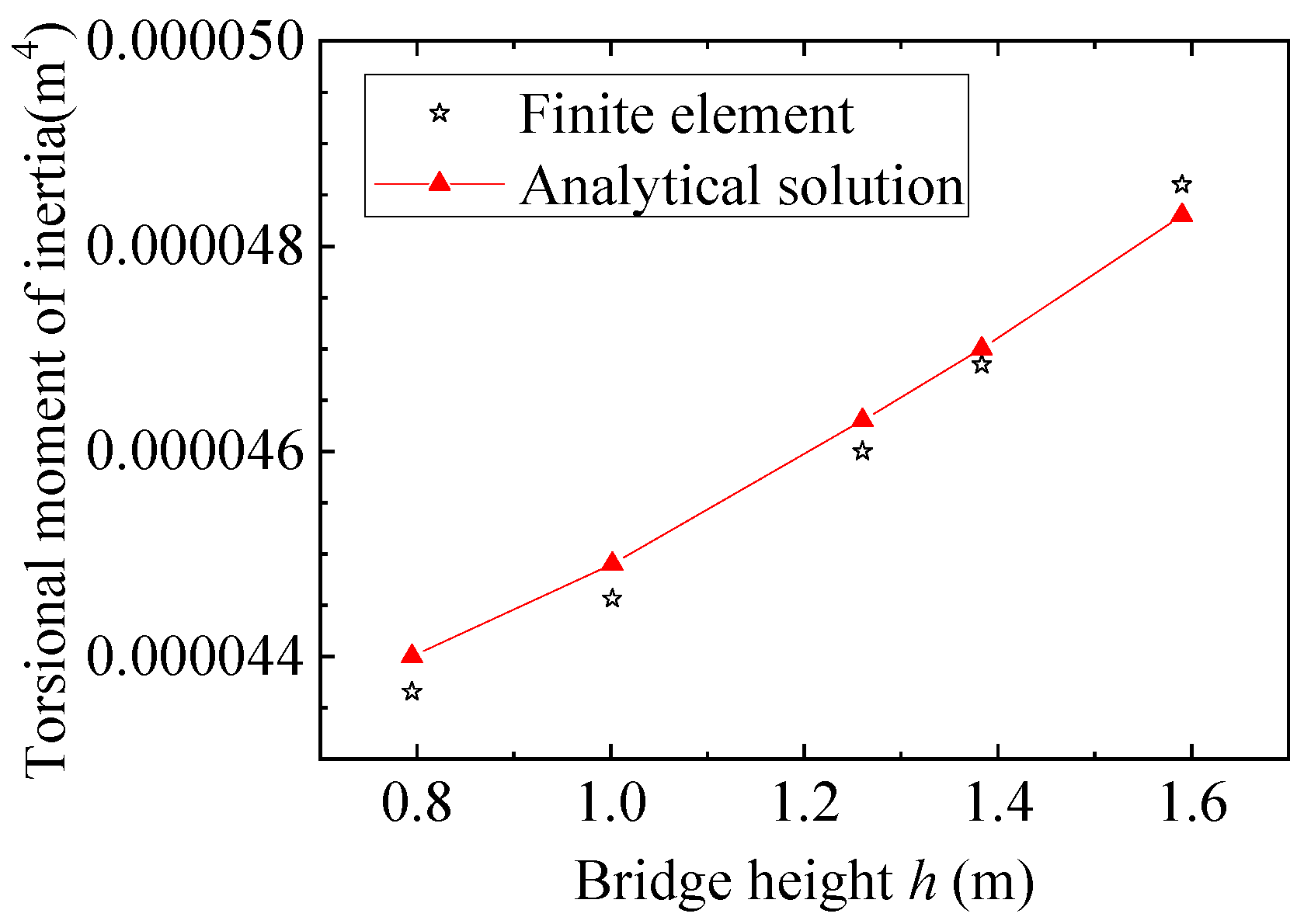
3.4.2. Validation by Case 2
4. Analysis of Parameters Influencing Torsional Stiffness
4.1. Theoretical Analysis of the Analytical Formula
4.2. Detailed Parameter Analysis and Discussion
4.2.1. b, Bridge Width
4.2.2. x, Bridge Length
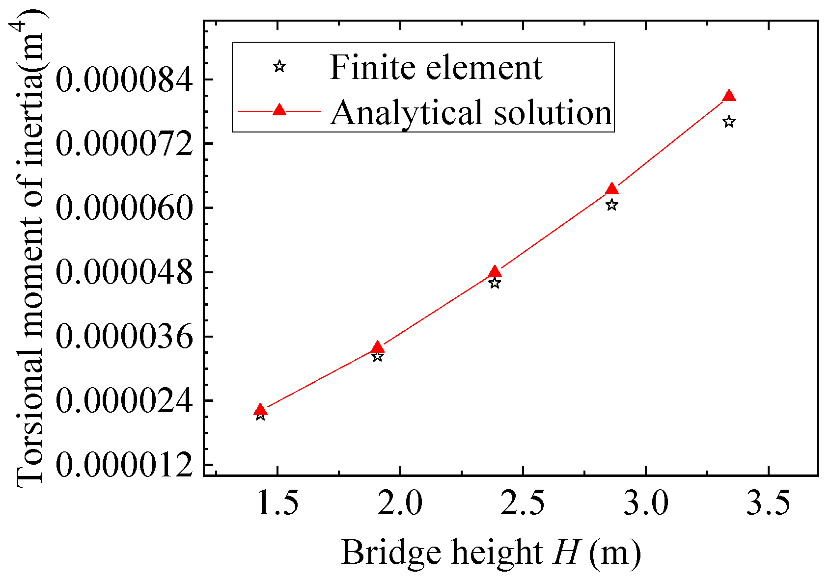
4.2.3. H, h and a
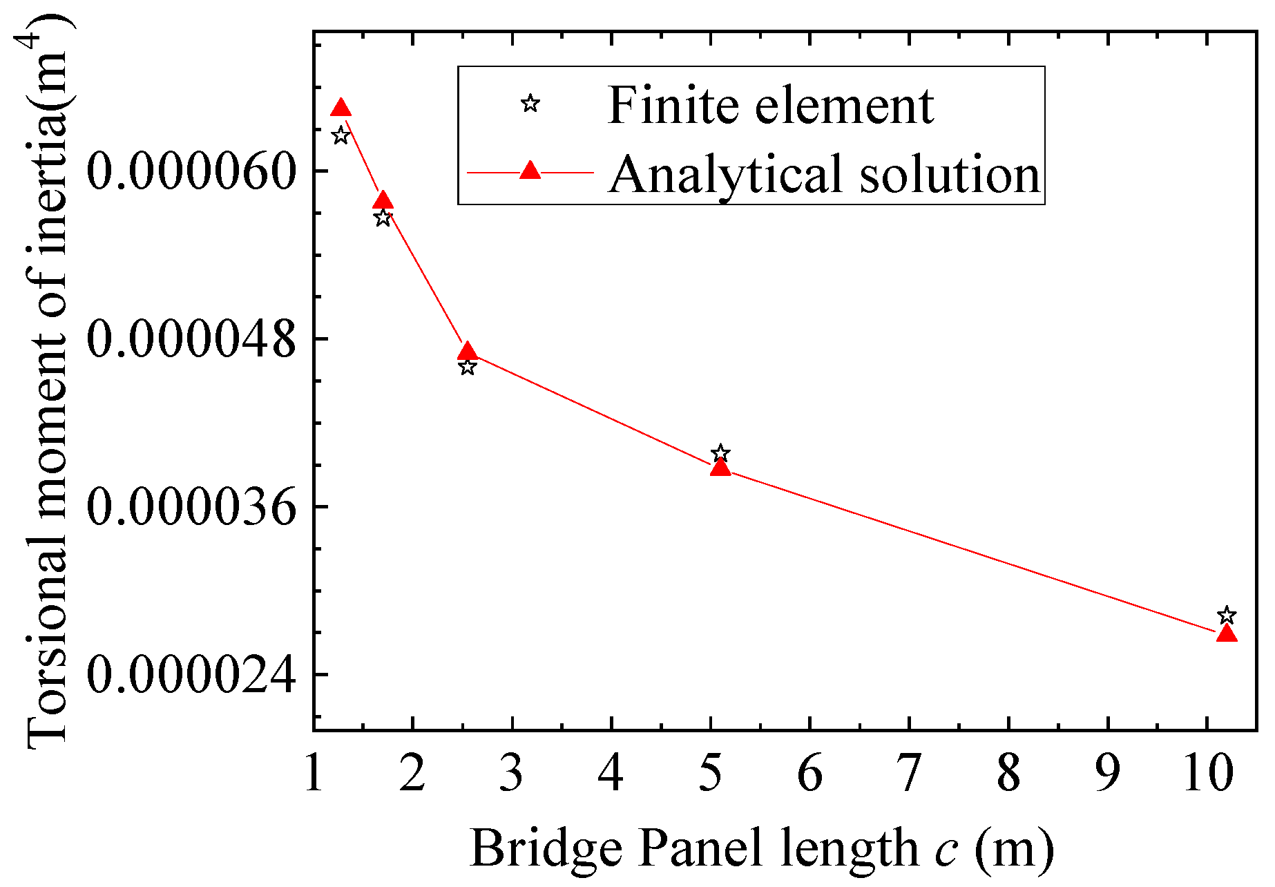
4.2.4. c, Truss Panel Length
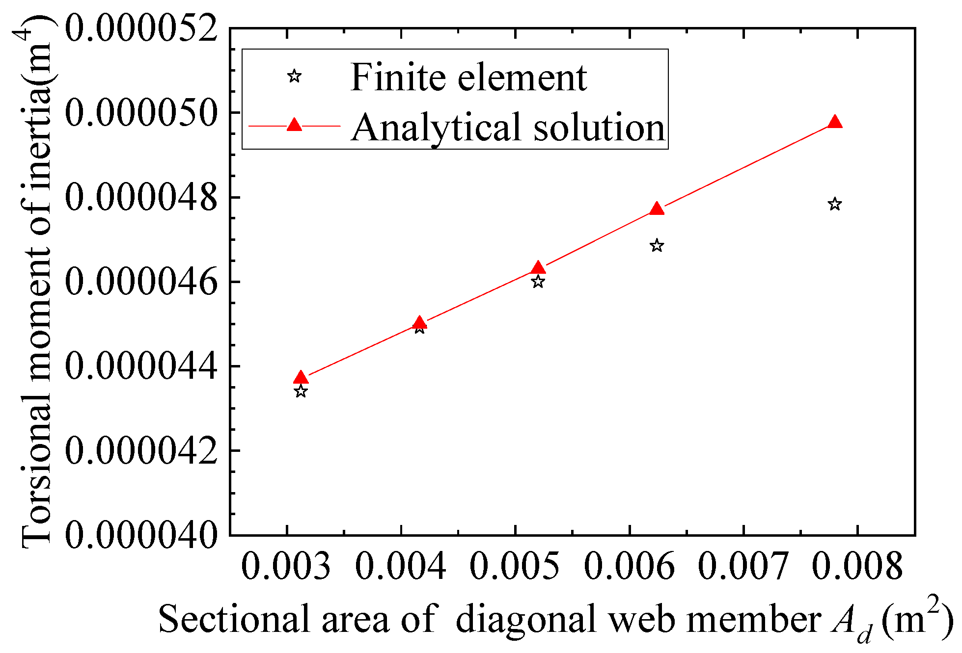
4.2.5. Ad, Area of Diagonal Web Members
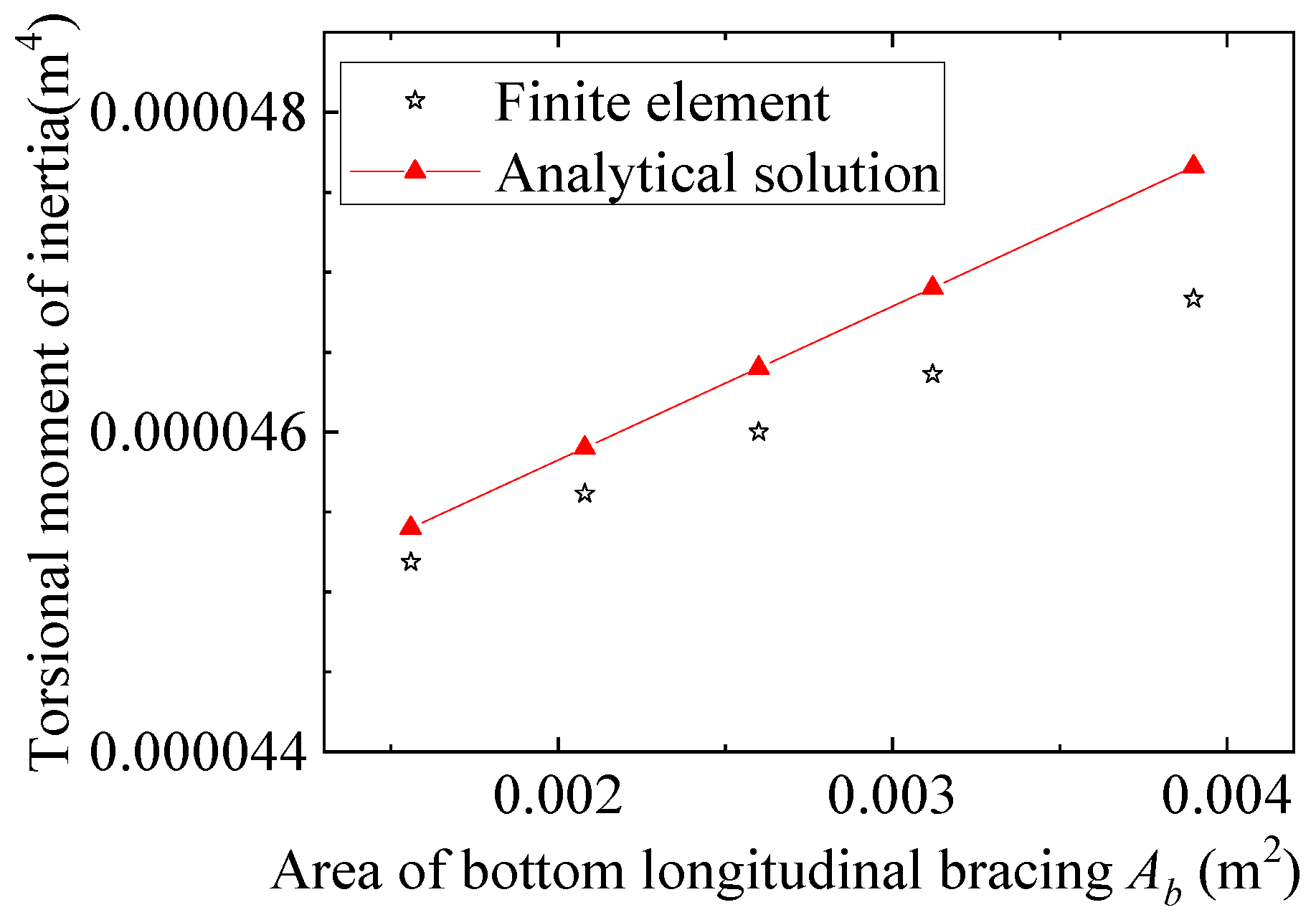
4.2.6. Ab, Area of Bottom Support
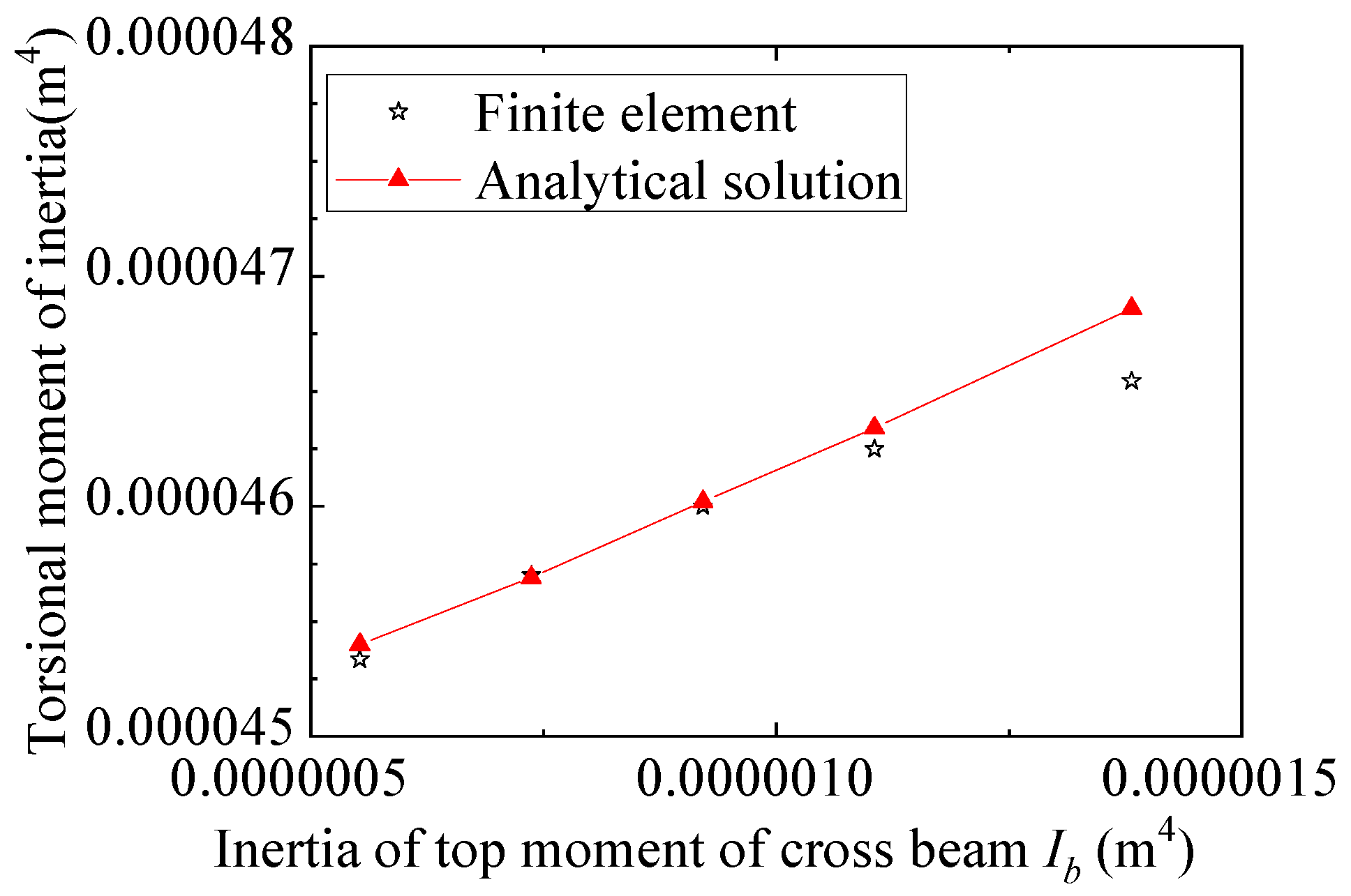
4.2.7. Ib, Horizontal Moment of Inertia of Top Cross Beam
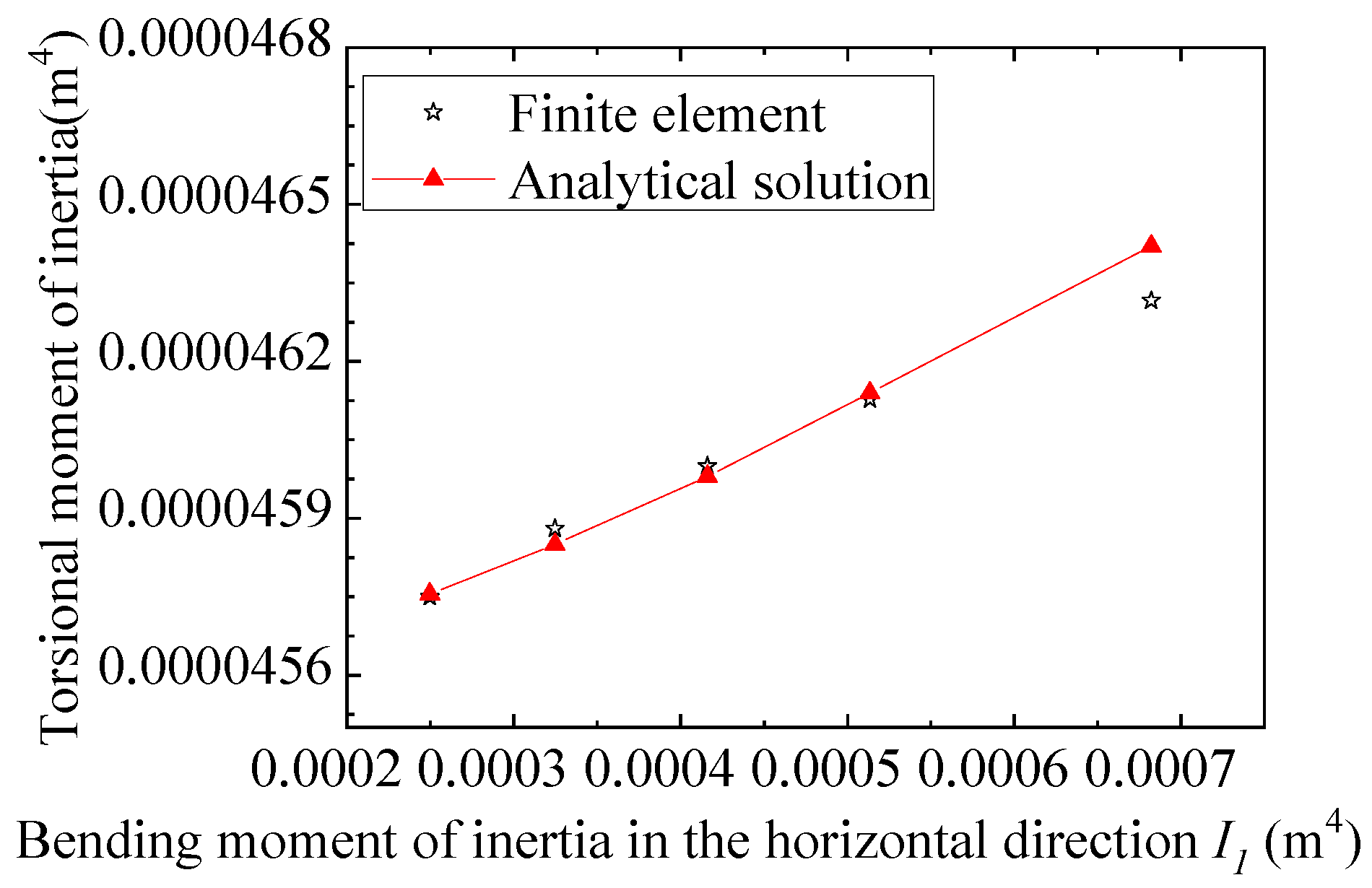
4.2.8. I1, Horizontal Moment of Inertia of Top Chord
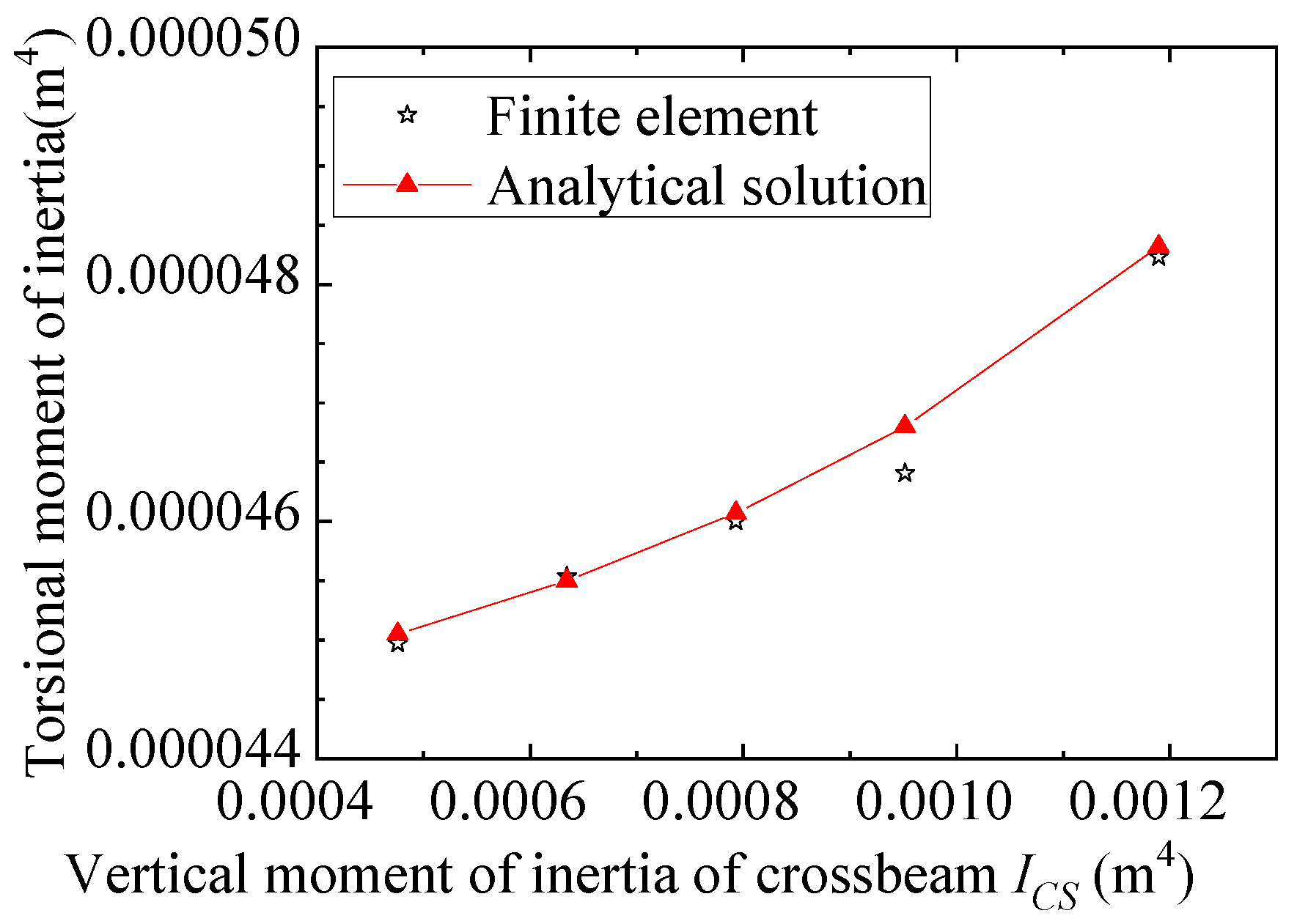
4.2.9. ICS, Vertical Moment of Inertia of Whole Cross Beam
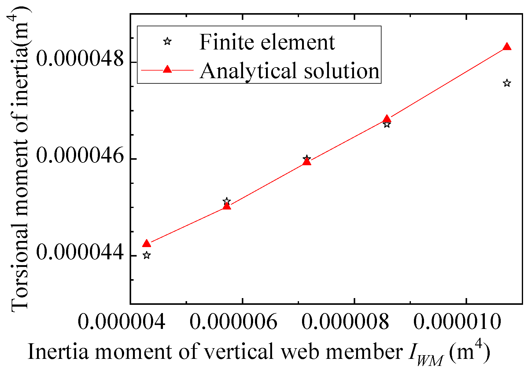
4.2.10. IWM, Moment of Inertia of Vertical Web Member
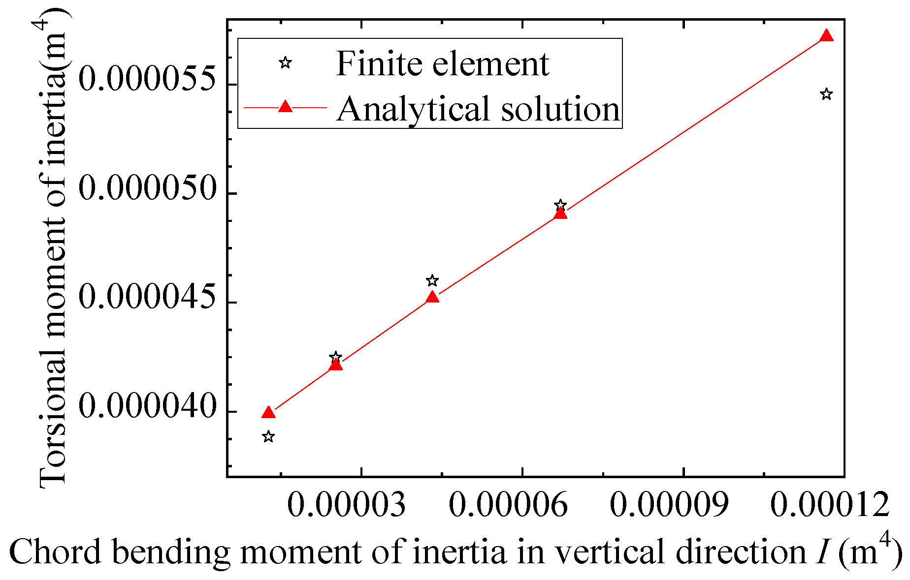
4.2.11. I, Vertical Moment of Inertia of the Chord
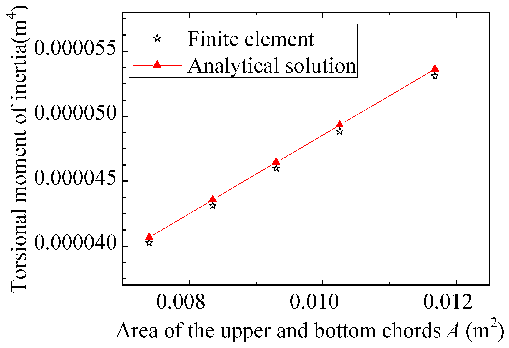
4.2.12. A, Area of the Chord
4.2.13. Discussion
5. Conclusions
Author Contributions
Funding
Data Availability Statement
Conflicts of Interest
Abbreviations
| Symbol | Description | Unit |
| Jf | The free torsional moment of inertia obtained from the existing formula | m4 |
| H | Bridge height | m |
| b | Bridge width | m |
| ts | The thickness of the side plate of the equivalent section | m |
| tb | The thickness of the bottom plate of the equivalent section | m |
| Jr | The restrained torsional moment of inertia | m4 |
| x | Distance from a given position along the cantilever to its root | m |
| It | Bending moment of inertia of one main truss in vertical direction | m4 |
| I | Upper and bottom chords’ bending moment of inertia in vertical direction | m4 |
| A | Area of the upper and bottom chords | m2 |
| JT | The overall torsional moment of inertia from the existing formula | m4 |
| c | Panel length | m |
| a | Length of the vertical web member above the top crossbeam | m |
| h | Length of the vertical web member below the top crossbeam | m |
| E | Elastic modulus | Pa |
| G | Shear modulus | Pa |
| Ad | The cross-sectional area of the diagonal web member | m2 |
| Ab | The cross-sectional area of the bottom X-shaped longitudinal bracing | m2 |
| tT | The thickness of the top plate of the equivalent section | m |
| Ic | The bending moment of inertia of the member with length c in Figure 5 | m4 |
| Ib | The bending moment of inertia of the member with length b in Figure 5 | m4 |
| JM | The modified free torsional moment of inertia | m4 |
| F | Concentrated force at the mid-span of each span of the continuous beam | N |
| ωm | The mid-span deflection of the m-th span of an elastically supported continuous beam | m |
| Sm | The coefficient that is multiplied by the mid-span deflection of the m-th span | / |
| Fm | One of the support reactions from the two supports of the m-th span | N |
| Fm+1 | Another of the support reactions from the two supports of the m-th span | N |
| I1 | Top chord’s bending moment of inertia in the horizontal direction | m4 |
| δ | The lateral deformation at the top chord position of the frame composed of web members and crossbeams when a unit lateral load is applied at the top chord position | m |
| IWM | The out-of-plane bending moment of inertia of the web member (the plane is the X-Z plane in Figure 3) | m4 |
| ICS | The bending moment of inertia in vertical direction of the combined section formed by Members 1 and 2 in Figure 6 (the vertical bending moment of inertia of the composite section of the crossbeam) | m4 |
| J′T | The overall torsional moment of inertia from the modified formula | m4 |
References
- Cusson, B. Modern Applications and Construction Details for Aluminium Bridges. Eng. Proc. 2023, 43, 13. [Google Scholar] [CrossRef] [Scilit]
- Wang, D.C.; Wang, Z.T. Application of Aluminum and Aluminum Alloys in Urban Construction and Auxiliary Facilities. Light Alloy Process. Technol. 2018, 46, 1–7. [Google Scholar] [CrossRef]
- Liu, P.; Lu, H.; Chen, Y.; Zhao, J.; An, L.; Wang, Y.; Liu, J. Fatigue Analysis of Long-Span Steel Truss Arched Bridge Part II: Fatigue Life Assessment of Suspenders Subjected to Dynamic Overloaded Moving Vehicles. Metals 2022, 12, 1035. [Google Scholar] [CrossRef] [Scilit]
- Wen, Q.J.; Yue, Z.X. Elastic Buckling Property of the Upper Chords in Aluminum Half-Through Truss Bridges. Structures 2020, 27, 1919–1929. [Google Scholar] [CrossRef] [Scilit]
- Jankowska-Sandberg, J.; Kołodziej, J. Experimental Study of Steel Truss Lateral-Torsional Buckling. Eng. Struct. 2013, 46, 165–172. [Google Scholar] [CrossRef] [Scilit]
- Lin, C.S.; Gerasimidis, S.; Betti, R. Progressive Collapse Analysis of Half-Through Truss Bridges Considering Corrosion Effects. Int. J. Steel Struct. 2025, 25, 959–973. [Google Scholar] [CrossRef] [Scilit]
- Yu, J.; Luo, Y. Influence of Torsion Stiffness of Spatial Truss String System on Structural Stability. J. Zhejiang Univ. (Eng. Sci.) 2013, 47, 1353–1360. [Google Scholar]
- Lu, C.; Yang, Z.; Li, P.; Zhang, X.; Huang, J.; Wang, L. Finite Element Analysis and Reinforcement of Steel Crane Beam under Eccentric Track Loading. Machines 2022, 10, 783. [Google Scholar] [CrossRef] [Scilit]
- Telgen, B.; Sigmund, O.; Kochmann, D.M. Topology Optimization of Graded Truss Lattices Based on On-the-Fly Homogenization. J. Appl. Mech. 2022, 89, 061006. [Google Scholar] [CrossRef] [Scilit]
- Qi, Q.M.; Shao, C.J.; Yang, H.P.; Cui, H.M.; Chen, Z.Q.; Gong, W.T. Axial-flexure-shear model for seismic analysis of RC thin-walled hollow piers. Soil Dyn. Earthq. Eng. 2025, 195, 109375. [Google Scholar] [CrossRef] [Scilit]
- Staszak, N.; Garbowski, T.; Szymczak-Graczyk, A. Solid Truss to Shell Numerical Homogenization of Prefabricated Composite Slabs. Materials 2021, 14, 4120. [Google Scholar] [CrossRef] [Scilit]
- Zhou, X.H.; Qin, F.J.; Di, J.; Zhang, Q.; Qiao, P. Continuous Analysis Method for Deck-Truss Composite Stiffening Girder Based on Energy Principle. China J. Highw. Transp. 2014, 27, 34–43. [Google Scholar] [CrossRef]
- Yue, Z.; Wen, Q.; Ding, Y. Research on Torsional Characteristic and Stiffness Reinforcement of Main Girder of Half-Through Truss Bridge. Sustainability 2022, 14, 6628. [Google Scholar] [CrossRef] [Scilit]
- Xu, G.N. Calculation of Torsional Moment of Inertia of Space Truss. J. Taiyuan Univ. Sci. Technol. 1984, 1, 46–57. [Google Scholar]
- Adamakos, T.; Vayas, I.; Petridis, S.; Panetsos, P. Modeling of Curved Composite I-Girder Bridges Using Spatial Systems of Beam Elements. J. Constr. Steel Res. 2011, 67, 462–470. [Google Scholar] [CrossRef] [Scilit]
- Vayas, I.; Adamakos, T.; Iliopoulos, A. Spatial Systems for Modelling Steel-Concrete Composite Bridges—Comparison of Grillage Systems and FE Models. Steel Constr. 2010, 3, 100–111. [Google Scholar] [CrossRef] [Scilit]
- Smyrnaios, S.V.; Iliopoulos, A.; Vayas, I. Truss Models for Inelastic Stability Analysis and Design of Steel Plate Girders. Eng. Struct. 2015, 105, 165–173. [Google Scholar] [CrossRef] [Scilit]
- Xiong, B.; Luo, X.L.; Tan, H.F. Analysis of Torsional Stiffness of All-Composite Truss. Acta Mater. Compos. Sin. 2015, 32, 501–507. [Google Scholar] [CrossRef]
- Li, Y.L.; Wang, L.; Xiang, H.Y.; Chen, X.Z. A Computational Method of Torsional Moment of Inertia of Plate Truss Girders. Eng. Mech. 2018, 35, 125–131. [Google Scholar] [CrossRef]
- Wang, K.; Wang, X.L.; Wang, J.Z.; Li, Y.Y.; Yin, Z.P. Equivalent Study on Stiffness of Space Truss Structure. J. Vib. Eng. 2025, 38, 931–940. [Google Scholar] [CrossRef]
- Bergenudd, J.; Battini, J.M.; Crocetti, R. Dynamic Analysis of a Pedestrian Timber Truss Bridge at Three Construction Stages. Structures 2024, 59, 105763. [Google Scholar] [CrossRef] [Scilit]
- Basaglia, C.; Camotim, D.; Silvestre, N. Torsion Warping Transmission at Thin-Walled Frame Joints: Kinematics, Modelling and Structural Response. J. Constr. Steel Res. 2012, 69, 39–53. [Google Scholar] [CrossRef] [Scilit]
- Zhang, H.; Deng, Y.; Chen, F.; Luo, Y.; Xiao, X.; Lu, N.; Liu, Y.; Deng, Y. Fatigue life prediction for orthotropic steel bridge decks welds using a Gaussian variational bayes network and small sample experimental data. Reliab. Eng. Syst. Saf. 2025, 264, 111406. [Google Scholar] [CrossRef] [Scilit]
- Wen, Q.J.; Yue, Z.X.; Liu, Z.J. Nonlinear Stability of the Upper Chords in Half-Through Truss Bridges. Steel Compos. Struct. 2020, 36, 307–319. [Google Scholar] [CrossRef]
- Siekierski, W. The U-Frame Concept to Assess the Stability of Chords of Warren-Truss Bridges with Independent Cross-Beam Decks. Steel Compos. Struct. 2024, 52, 77–87. [Google Scholar] [CrossRef]
- Huang, H.H.; Chen, K.M.; Wu, Q.X.; Nakamura, S. Calculation Method for Flexural Bearing Capacity of Composite Girders with CFST Truss Chords. J. Bridge Eng. 2023, 28, 04023019. [Google Scholar] [CrossRef] [Scilit]
- Wang, X.; Qiu, Y.; Yuan, J.; Liu, D.; Shi, P.; Zhao, C.; Xu, S.; Zhao, T. Theoretical and Numerical Simulation Study on the Ultimate Load Capacity of Triangular and Quadrilateral Truss Structures. Buildings 2024, 14, 928. [Google Scholar] [CrossRef] [Scilit]
- Ma, Y.; Yang, Z.; Liu, Y.; Liu, J.; Zhao, W.; Qiu, R.; Chen, X.; Qiao, Y.; Deng, Y. Flexural Behavior of Rectangular Concrete Filled Steel Tubular (RCFST) Composite Truss Bridge. Structures 2025, 72, 108260. [Google Scholar] [CrossRef] [Scilit]
- Huang, W.; Lai, Z.; Chen, B.; Xie, Z.; Varma, A.H. Concrete-Filled Steel Tube (CFT) Truss Girders: Experimental Tests, Analysis, and Design. Eng. Struct. 2018, 156, 118–129. [Google Scholar] [CrossRef] [Scilit]
- Chen, F.; Liu, X.; Zhang, H.; Luo, Y.; Lu, N.; Liu, Y.; Xiao, X. Assessment of fatigue crack propagation and lifetime of double-sided U-rib welds considering welding residual stress relaxation. Ocean Eng. 2025, 332, 121400. [Google Scholar] [CrossRef] [Scilit]
- Chen, H.; Zeng, Q.Y. Calculation of torsion center position of box girder. J. Railw. Sci. Eng. 2004, 1, 74–77. [Google Scholar] [CrossRef]
- Romano, G.; Rosati, L.; Ferro, G. Shear Deformability of Thin-Walled Beams with Arbitrary Cross-Sections. Int. J. Numer. Methods Eng. 1992, 35, 283–306. [Google Scholar] [CrossRef] [Scilit]











| Member | Member Cross-Section | Dimensions | Vertical Moment of Inertia | Lateral Moment of Inertia |
|---|---|---|---|---|
| Top and bottom chords |  | W = 90 mm B = 230 mm K = 160 mm t = 12 mm | 4.32 × 107 mm4 | 4.16 × 108 mm4 |
| Web member of the main truss |  | W = 160 mm B = 120 mm t = 10 mm | 1.14 × 107 mm4 | 1.81 × 107 mm4 |
| Top member of the crossbeam and web member of the crossbeam | | W = 70 mm B = 70 mm t = 5 mm | 9.21 × 105 mm4 | 9.21 × 105 mm4 |
| Bottom member of the crossbeam |  | W = 70 mm B = 70 mm K = 120 mm t = 5 mm | 1.84 × 106 mm4 | 2.53 × 107 mm4 |
| The X-shaped bottom horizontal frame | | W = 70 mm B = 70 mm K = 20 mm t = 5 mm | 1.84 × 106 mm4 | 7.11 × 106 mm4 |
| Member | Member Cross-Section | Dimensions | Vertical Moment of Inertia | Lateral Moment of Inertia |
|---|---|---|---|---|
| Top and bottom chords | | W = 100 mm B = 220 mm K = 120 mm t = 4 mm | 3.62 × 107 mm4 | 6.15 × 107 mm4 |
| Web member of the main truss | | W = 120 mm B = 100 mm t = 9 mm | 5.31 × 106 mm4 | 7.15 × 106 mm4 |
| Top member of the crossbeam and web member of the crossbeam | | W = 100 mm B = 70 mm t = 9 mm | 1.90 × 106 mm4 | 3.44 × 106 mm4 |
| Bottom member of the crossbeam | | W = 70 mm B = 70 mm K = 100 mm t = 7.5 mm | 3.95 × 106 mm4 | 3.82 × 107 mm4 |
| The X-shaped bottom horizontal frame | No bottom brace | No bottom brace | No bottom brace | No bottom brace |
| Equation | Beam Length-10.2 m | Beam Length-15.3 m | Beam Length-30.6 m | Beam Length-45.9 m | Beam Length-61.2 m |
|---|---|---|---|---|---|
| Equation (4) | 23.5% | 20.2% | 21.0% | 33.8% | 29.3% |
| Equation (13) | 13.0% | 9.1% | 13.5% | 16.4% | 26.8% |
| Equation | Beam Width-1.5 m | Beam Width-3.0 m | Beam Width-4.5 m | Beam Width-6.0 m | Beam Width-7.5 m | Beam Width-9.0 m |
|---|---|---|---|---|---|---|
| Equation (4) | 19.9% | 19.0% | 30.2% | 36.3% | 39.7% | 40.0% |
| Equation (13) | 8.1% | 16.3% | 16.9% | 6.8% | 9.0% | 14.6% |
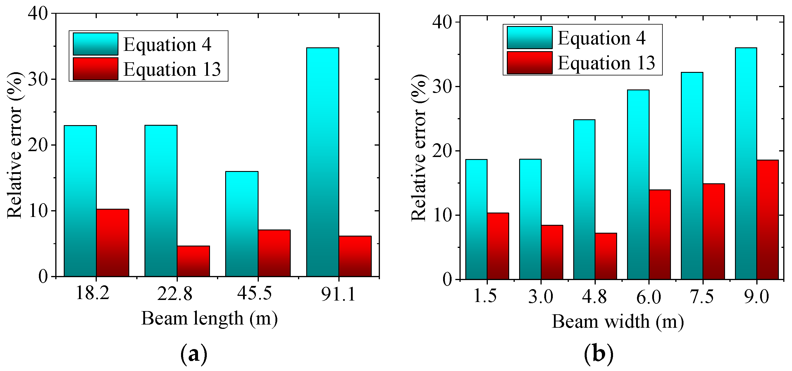
| Equation | Beam Length-18.2 m | Beam Length-22.8 m | Beam Length-45.5 m | Beam Length-91.1m |
|---|---|---|---|---|
| Equation (4) | 22.9% | 21.9% | 15.9% | 34.75% |
| Equation (13) | 10.2% | 4.6% | 7.1% | 6.1% |
| Equation | Beam Width-1.5 m | Beam Width-3.0 m | Beam Width-4.8 m | Beam Width-6.0 m | Beam Width-7.5 m | Beam Width-9.0 m |
|---|---|---|---|---|---|---|
| Equation (4) | 18.6% | 18.9% | 24.8% | 29.4% | 32.2% | 36.4% |
| Equation (13) | 10.3% | 8.4% | 7.2% | 13.9% | 14.8% | 18.5% |
| First-Level Parameter | Exponent | Second-Level Parameter | Exponent | Third-Level Parameter | Exponent |
|---|---|---|---|---|---|
| b | ≈1 | / | / | / | / |
| h | ≈1 | / | / | / | / |
| ts | ≈1 | c | ≈−2 | / | / |
| H | ≈−2 | / | / | ||
| Ad | 1 | / | / | ||
| tb | ≈1 | c | ≈−2 | / | / |
| b | ≈−2 | / | / | ||
| Ab | 1 | / | / | ||
| tT | ≈1 | Ib | ≈1 | / | / |
| Ic | ≈1 | I1 | ≈1 | ||
| a | ≈−2 | ||||
| c | ≈0 | ||||
| b | ≈−1 | ||||
| h | ≈−2 | ||||
| ICS | ≈1 | ||||
| IWM | ≈1 | ||||
| c | −1 | / | / | ||
| b | −1 | / | / |
| First-Level Parameter | Exponent | Second-Level Parameter | Exponent |
|---|---|---|---|
| b | 2 | / | / |
| x | −2 | / | / |
| It | ≈1 | I | 1 |
| H | 2 | ||
| A | 1 |
Disclaimer/Publisher’s Note: The statements, opinions and data contained in all publications are solely those of the individual author(s) and contributor(s) and not of MDPI and/or the editor(s). MDPI and/or the editor(s) disclaim responsibility for any injury to people or property resulting from any ideas, methods, instructions or products referred to in the content. |
© 2026 by the authors. Licensee MDPI, Basel, Switzerland. This article is an open access article distributed under the terms and conditions of the Creative Commons Attribution (CC BY) license.
Share and Cite
Yue, Z.; Lin, S.; Zhao, R.; Zhang, B. Calculation Method for Torsional Moment of Inertia of Half-Through Truss Bridges. Buildings 2026, 16, 2108. https://doi.org/10.3390/buildings16112108
Yue Z, Lin S, Zhao R, Zhang B. Calculation Method for Torsional Moment of Inertia of Half-Through Truss Bridges. Buildings. 2026; 16(11):2108. https://doi.org/10.3390/buildings16112108
Chicago/Turabian StyleYue, Zixiang, Siyuan Lin, Rui Zhao, and Bin Zhang. 2026. "Calculation Method for Torsional Moment of Inertia of Half-Through Truss Bridges" Buildings 16, no. 11: 2108. https://doi.org/10.3390/buildings16112108
APA StyleYue, Z., Lin, S., Zhao, R., & Zhang, B. (2026). Calculation Method for Torsional Moment of Inertia of Half-Through Truss Bridges. Buildings, 16(11), 2108. https://doi.org/10.3390/buildings16112108