Article

Study on Dynamic Evolution of Anti-Penetration Performance of Polyurea Reinforced Concrete Target Based on FE-SPH Coupling Method


1
School of Architecture Engineering, Shaanxi A&F Technology University, Xianyang 712100, China
2
Earthquake Engineering Research and Test Center, Guangzhou University, Guangzhou 510405, China
3
Key Laboratory of Earthquake Resistance, Earthquake Mitigation and Structural Safety, Ministry of Education, Guangzhou 510405, China
4
Tianjin Key Laboratory of Prefabricated Buildings and Intelligent Construction, School of Civil and Transportation Engineering, Hebei University of Technology, Tianjin 300401, China
*
Authors to whom correspondence should be addressed.
Buildings 2026, 16(11), 2076; https://doi.org/10.3390/buildings16112076
Submission received: 1 April 2026 / Revised: 6 May 2026 / Accepted: 20 May 2026 / Published: 23 May 2026
(This article belongs to the Section Building Materials, and Repair & Renovation)

Abstract

Addressing the issues of brittle spalling and debris scattering commonly observed in Normal Concrete (NC) under high-velocity impact loading, this study investigates the resistance of polyurea-reinforced concrete targets against high-velocity bullet penetration. High-velocity projectile penetration tests were conducted at approximately 510 m/s to comparatively analyze the failure modes of plain concrete targets and targets reinforced with polyurea coatings of varying thicknesses. Furthermore, a three-dimensional numerical model based on the coupled Finite Element-Smoothed Particle Hydrodynamics (FE-SPH) algorithm was constructed to overcome the numerical instabilities inherent in traditional finite element methods when handling large material deformations and debris flows. The experimental results indicate that while the polyurea coating has a limited direct effect on reducing the depth of penetration (DOP)—showing marginal reductions of 1.8% and 2.3% for 2 mm and 5 mm coatings, respectively—it demonstrates a significant physical confinement effect. Notably, the 5 mm polyurea coating effectively suppresses brittle spalling on the impact face, reducing the crater diameter by 15.5% compared to the plain concrete target and restricting the propagation of radial cracks. Energy analysis and interface pressure monitoring reveal that the polyurea coating employs a “peak-shaving and valley-filling” mechanism driven by mechanical impedance mismatch, transforming transient impacts into steady-state compression with lower energy density. Consequently, this significantly enhances the overall impact toughness and secondary protection capability of the structure. These findings provide critical references for the refined reinforcement design of existing defensive structures.

1. Introduction

Ordinary concrete (NC) is widely utilized in various building structures due to its low cost and ease of construction. However, owing to the inherent brittleness of NC materials, they often exhibit both local and global failures when subjected to extreme loads such as impact or explosion. Under low-energy impact, failure is predominantly characterized by flexural mechanisms; as energy increases, the failure mode transitions to combined flexural-shear damage and eventually to severe shear failure accompanied by violent spalling. Such failure modes not only compromise the load-bearing capacity of structures but may also trigger catastrophic consequences like progressive collapse. Furthermore, high-velocity concrete fragments generated during failure can cause secondary injuries to surrounding personnel and equipment. Therefore, to enhance the resistance of NC structures under extreme loading conditions, implementing appropriate strengthening strategies is crucial for improving structural stability. Regarding improvements to the intrinsic properties of concrete, primary approaches include increasing the concrete strength grade [1,2,3,4] and replacing ordinary concrete with fiber-reinforced composite materials, such as Engineered Cementitious Composites (ECC) [5,6] or Ultra-High Performance Concrete (UHPC) [7,8,9]. However, these methods are generally applicable only during the design phase of new constructions. The second approach involves external strengthening, which upgrades existing structures without altering their internal configuration. Techniques include applying steel jackets [10,11], Fiber-Reinforced Polymer (FRP) plates [12,13] or laminates [14,15], advanced fiber-reinforced concrete layers [16,17], composite metal structures (e.g., aluminum foam [18,19], honeycomb cores [20,21], or sandwich panels [22]), and soft polymer coatings [23,24].
Recently, soft polymer coatings—particularly polyurea—have emerged as a minimally invasive alternative to conventional methods. Polyurea can be directly spray-applied, requiring no complex surface treatment or mechanical anchorage. Unlike rigid steel or FRP jackets that restrict deformation, polyurea’s exceptional ductility and viscoelasticity enable effective stress transfer and energy dissipation under dynamic loads. Due to its lightweight nature, high tensile strength, and robust adhesion to various substrates, polyurea is considered an ideal coating for enhancing structural resistance against high-velocity impact and penetration. In recent years, polyurea elastomers have been extensively employed in research on blast and impact resistance of concrete protective structures [25,26], owing to their superior dynamic energy dissipation and ductility characteristics. Blast tests conducted by the U.S. Air Force Laboratory demonstrated that applying a polyurea coating to the surface of concrete masonry walls significantly enhances their blast resistance, with the thickness and placement of the polyurea layer playing critical roles in protective performance. Subsequent studies further confirmed that polyurea not only improves the blast resistance of concrete structural components but also effectively captures fragments generated by blast loading, thereby mitigating secondary hazards [27,28]. In the realm of low-to-medium velocity impact, numerous investigations have further validated the protective efficacy of polyurea coatings on concrete structures. Luo [29] studied the dynamic response of ordinary reinforced concrete beams coated with polyurea under single and multiple impacts, combining low-velocity drop-weight impact experiments with numerical simulations, which indicated that the polyurea coating substantially reduces both maximum and residual deflections of the beams, significantly enhancing their impact resistance. Fallon [30] experimentally evaluated the impact performance of polyurea-coated concrete targets subjected to flat-nosed projectile impacts at velocities ranging from 45 to 150 m/s, which revealed that uncoated targets suffered severe damage at an impact velocity of 60 m/s, whereas polyurea-coated targets required an impact velocity of 120 m/s to reach a comparable level of damage.
While polyurea has proven effective in blast mitigation and low-velocity impact scenarios, research on its performance under high-velocity projectile penetration remains limited. Numerical modeling of these events using the conventional Finite Element Method (FEM) often faces significant hurdles. Specifically, FEM relies on element deletion to simulate damage, which fails to describe the continuous debris flow and its secondary impact on the coating. Furthermore, extreme material distortion during penetration frequently leads to numerical instability and negative volume errors [31].
To overcome the limitations of continuum-based methods in capturing the heterogeneous nature of concrete, researchers have increasingly turned to discrete modeling approaches. For instance, Smith et al. [32] successfully utilized a Lattice Particle Model (LPM) to simulate projectile penetration in ultra-high-performance concrete (UHPC), providing a robust framework for predicting localized damage patterns and discrete cracking at the meso-scale. Similarly, Feng et al. [33] performed experimental and numerical analyses on armor-piercing projectiles penetrating double-layered targets of ultra-high-performance fiber-reinforced concrete (UHPFRC) and armor steel, demonstrating that discrete-based models can effectively account for the complex fracture mechanisms inherent in cementitious composites.
While these discrete models offer high fidelity in describing crack branching and fragmentation, they often incur high computational costs for large-scale structural analysis. Consequently, the coupled FE-SPH strategy has emerged as a balanced alternative. By introducing Smoothed Particle Hydrodynamics (SPH) [34,35] in high-strain zones and retaining FEs [36] in far-field regions, this approach balances computational efficiency with the ability to capture fragment ejection and coating tearing. Recent advances have further improved the handling of material discontinuities in laminated composites. To analyze structures under blast loading, Xu et al. [37] proposed a numerical model based on the coupled FE-SPH method. Similarly, Caleyron et al. [38] developed a coupled FE-SPH computational model for reinforced concrete, evaluating the stability of reinforced concrete structures subjected to projectile impact. Experimental studies by De et al. [39] demonstrated that the coupled FE-SPH algorithm effectively addresses concrete explosion problems. Yang et al. [40] pointed out that this algorithm, when applied to hypervelocity impact materials, overcomes the instability drawbacks of the standalone SPH method during tensile processes, while also yielding more accurate computational results. To address complex interactions in composite structures, Khayyer et al. [41] developed a fully Lagrangian meshfree solver coupling Incompressible SPH (ISPH) and Hamiltonian SPH (HSPH), which accurately captures hydroelastic fluid–structure interactions in laminated composites and handles severe material property discontinuities at interfaces without the need for artificial stabilizers. Furthermore, Karmakar et al. [42] employed a hybrid discretization technique combining finite elements and SPH, investigated the dynamic response characteristics of reinforced concrete slabs under blast impact loads and analyzed the influence of different boundary conditions on the overall structural response. Wang et al. [43] utilized a quasi-static and dynamic stress-coupled FE-SPH approach to study the fracture morphology of silicate glass under projectile impact. When addressing problems involving large material deformations, such as impact and explosion, the coupled FE-SPH algorithm delivers stable results with high accuracy. However, systematic studies regarding the complex interfacial bonding failure and debris suppression mechanisms of polyurea under high-velocity penetration are still lacking.
Based on this, this study focuses on the protective mechanism of polyurea coatings under high-velocity projectile penetration. The primary objectives are to:
(1)
Experimentally evaluate the macroscopic failure characteristics of polyurea-coated concrete targets at impact velocities of approximately 510 m/s using a large-caliber powder gun.
(2)
Develop a coupled FE-SPH numerical model to overcome convergence challenges induced by extreme material deformation, ensuring a precise simulation of the penetration process.
(3)
Elucidate the synergistic reinforcement mechanism by distinguishing two core functions: “Dynamic Confinement,” which occurs at the microsecond scale to regulate initial stress wave propagation and mitigate peak pressure through impedance matching, and “Physical Confinement,” which acts during the millisecond-scale penetration phase to maintain structural integrity by capturing fragments and suppressing spalling.
(4)
Quantify the energy dissipation pathways to provide a scientific and theoretical foundation for the design of resilient protective structures in high-velocity impact environments.

2. Experimental Programme

2.1. Material Characterization

The composite targets with varying thicknesses were fabricated by directly spraying polyurea material onto the surface of concrete targets using a two-component thermal spray process. The polyurea material employed was LINE-X 350, supplied by LINE-X Protective Coatings, Beijing China. Its material properties are listed in Table 1. Notably, the thermal spray process involves high-pressure and high-temperature application, which allows the polyurea to penetrate deeply into the micro-pores of the concrete surface. This ensures strong interfacial adhesion through micro-mechanical interlocking, eliminating the need for complex surface treatments or additional mechanical anchoring while maintaining the integrity of the coating–substrate interface under high-velocity impact.
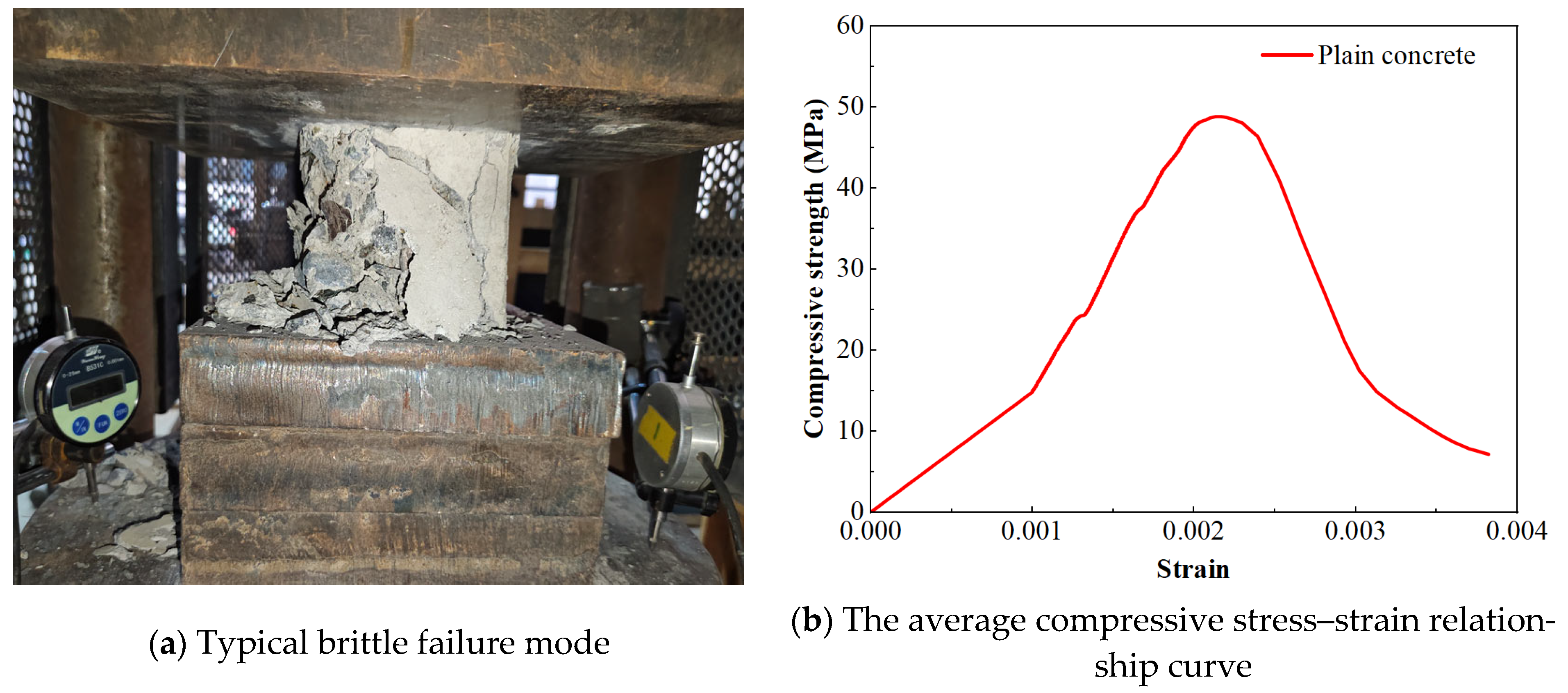
Prior to conducting high-velocity impact tests, the uniaxial compression tests were performed on a total of three concrete cubic specimens with dimensions of 100 mm × 100 mm × 100 mm to determine the material properties presented herein. Figure 1b presents the corresponding average compressive stress–strain relationship curve, demonstrating a rapid stress drop post-peak. The specimens yielded an average compressive strength of 50.2 MPa, with a standard deviation of 1.8 MPa and a coefficient of variation (COV) of 3.6%. This low level of dispersion indicates high consistency in the material preparation and casting process, providing a stable baseline for the subsequent penetration simulations. Figure 1a illustrates the typical failure mode and crack patterns of the cubic specimens under compressive loading. The specimens exhibited distinct brittle failure characteristics, characterized by major longitudinal cracks propagating parallel to the loading direction, accompanied by concrete spalling.

2.2. High-Velocity Impact Experiments

2.2.1. Concrete Target Data

Three cylindrical concrete targets of identical dimensions were designed for this study, comprising one PCT-0 (denoted as PCT-0) and two polyurea-coated concrete targets with varying coating thicknesses (denoted as PCT-2 and PCT-5, where the numerals indicate the respective polyurea coating thickness in millimeters). The targets featured a base diameter of 800 mm. The target thickness was conservatively set at 450 mm, based on a magnified value of the theoretical penetration depth calculated using the modified Petry formula [44], a semi-empirical approach widely used to estimate the maximum penetration depth (x) in concrete:
x = 12 K p A p log 10 ( 1 + V 2 215000 )
where Kp represents the penetrability coefficient of the concrete, Ap is the sectional area of the projectile, and V is the impact velocity. By applying the material properties of NC and a target velocity of 510 m/s, the calculated theoretical depth was significantly less than 450 mm, ensuring a “semi-infinite” target condition for studying cratering and interfacial behavior. To eliminate the influence of lateral stress waves, the target diameter exceeded 30 times the projectile diameter (d = 25 mm), which boundary effects were deemed negligible [45].
The selection of 2 mm and 5 mm coating thicknesses was based on both practical engineering standards and prior research. A 2 mm coating is often considered the minimum effective thickness for “shrapnel containment” in protective retrofitting [28], while 5 mm represents a robust reinforcement level that significantly enhances energy dissipation without excessively increasing the structural weight or cost [31,46]. Comparing these two levels allows for a systematic analysis of the “thickness effect” on fragment suppression.

2.2.2. Projectile Details

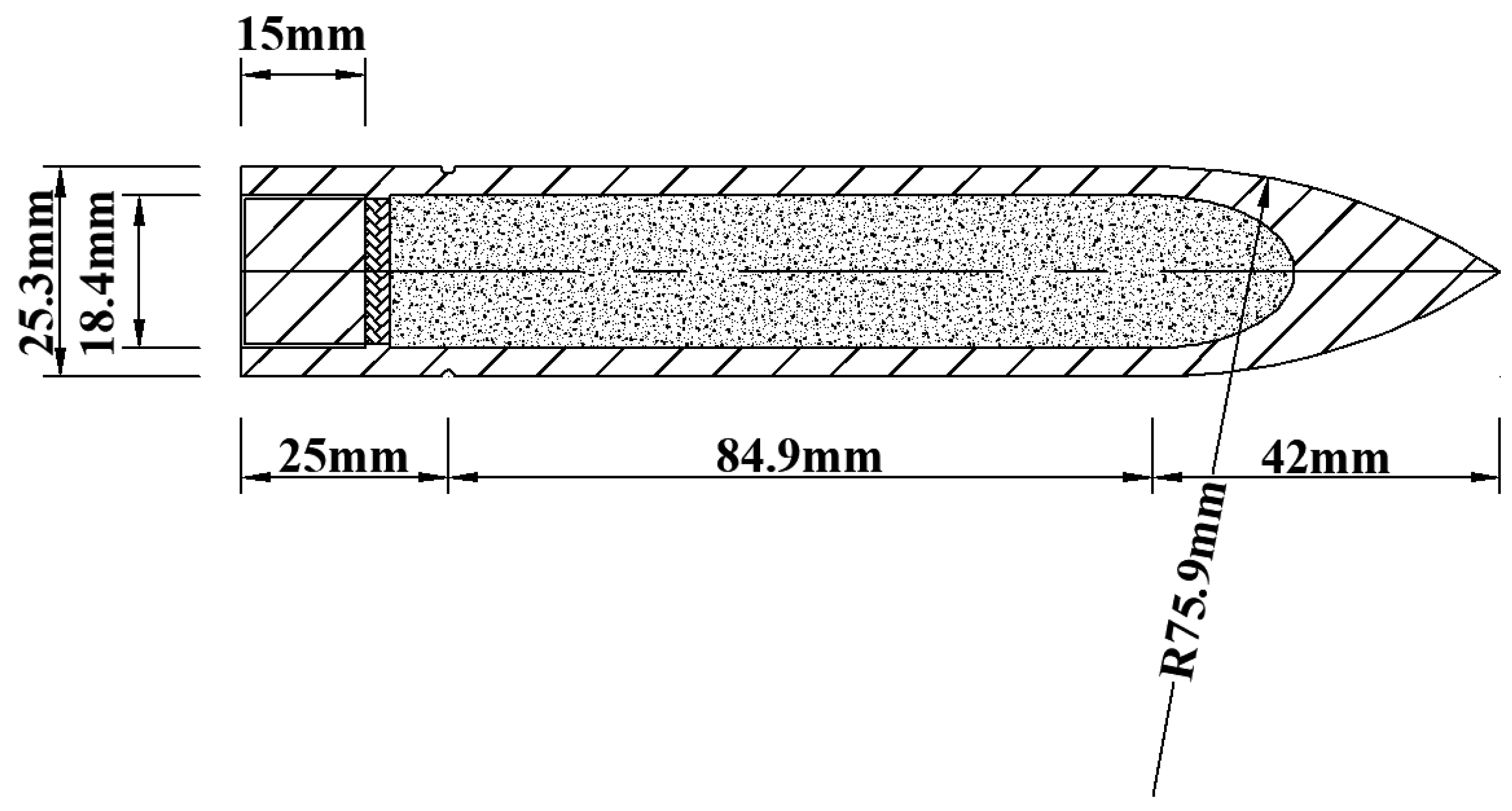
Figure 2 illustrates the ogive-nosed projectile employed in this study. The choice of an ogive nose with a caliber-radius-head (CRH) of 3.0 was intended to balance aerodynamic stability during flight with high penetration efficiency upon impact. The projectile dimensions (length of 152 mm and diameter of 25 mm) and mass (330 g) were specifically calibrated to match the internal ballistics of the large-caliber smoothbore powder gun system. This specific mass-to-velocity ratio ensures that the projectile carries sufficient kinetic energy at 510 m/s to induce significant nonlinear damage and fragment ejection in NC targets, which is essential for evaluating the polyurea coating’s containment capabilities.
The projectile shell was machined from high-strength DT300 (SiMnCrNiMoV) steel to prevent excessive projectile deformation or premature fracture during penetration, thereby focusing the study on target damage. The core was filled with an inert resin to maintain the center of gravity and structural integrity. For every test, a new projectile was utilized to ensure experimental consistency and eliminate the effects of cumulative fatigue.

2.2.3. Test Setup

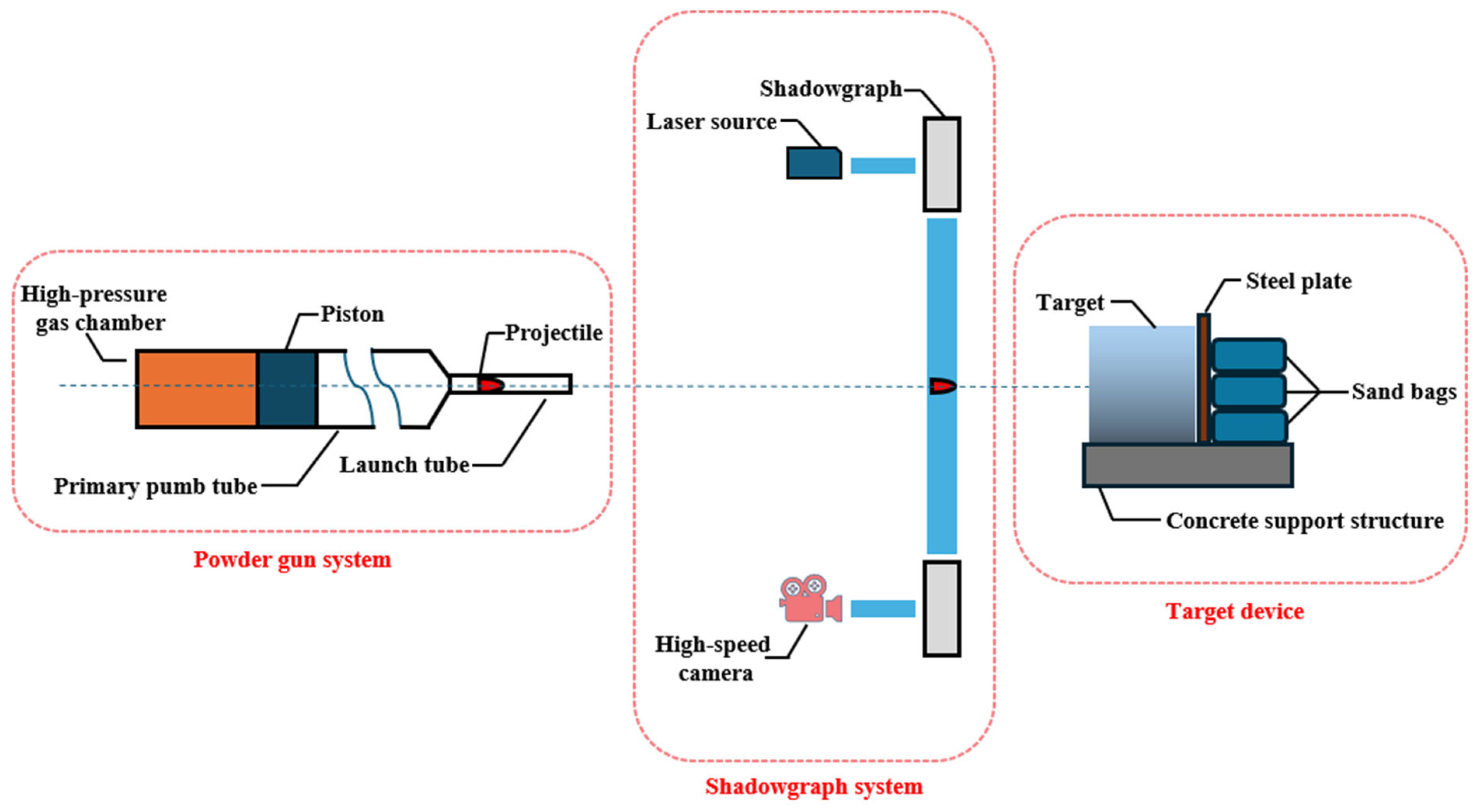
Figure 3 presents a schematic diagram of the experimental setup for high-velocity projectile impact on concrete targets. The cylindrical concrete target was placed within a recessed concrete support structure, with its impact face oriented perpendicular to the ground and aligned with the central axis of both the launching system and the velocity measurement apparatus to ensure precise impact alignment. To prevent potential damage to the experimental environment caused by projectile perforation, a protective barrier consisting of an 800 mm-thick steel plate followed by sandbags was installed behind the target.
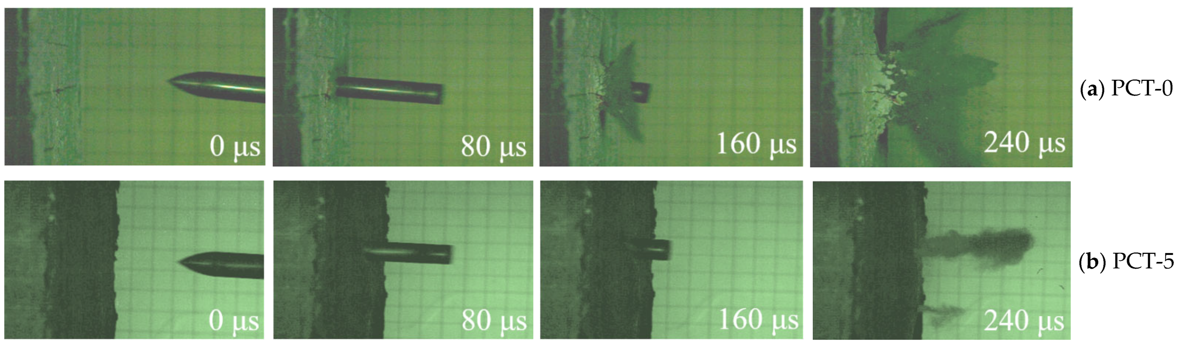
Figure 4 illustrates the temporal evolution of the projectile penetration process and the corresponding distribution of ejected fragments, captured by a high-speed camera (Photron SA-Z, Tokyo Japan). Taking PCT-0 and PCT-5 at an impact velocity of approximately 510 m/s as examples, a distinct difference in fragment mitigation is observable. While PCT-0 (Figure 4a) exhibits a severe ejection of a debris cloud from the impact face at 240 μs, the polyurea layer on PCT-5 (Figure 4b) effectively contains the concrete fragments, demonstrating its superior physical constraint capability.

2.3. Result Analysis and Discussions

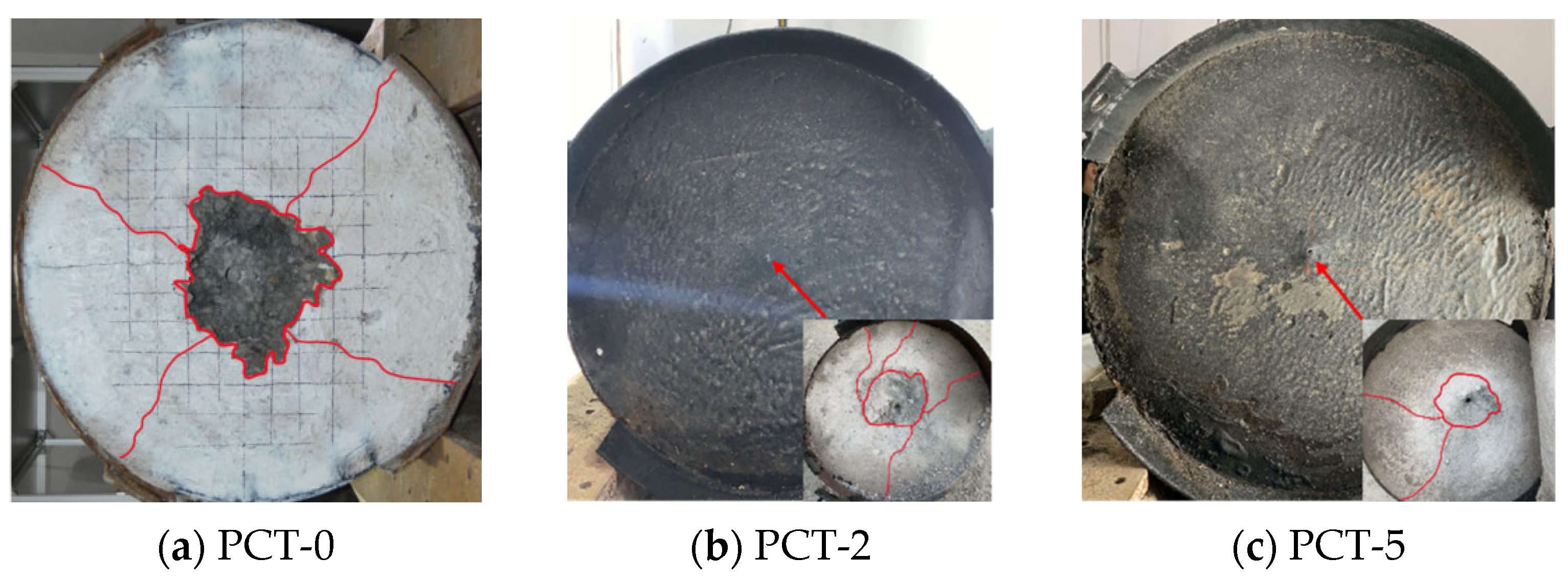
Following the completion of the impact tests, key metrics including the projectile depth of penetration (DOP) and the crater diameter (dc) were recorded, as shown in Table 2. Figure 5 illustrates the local damage morphologies of the three target specimens. For the uncoated PCT-0 (Figure 5a), extensive cratering and significant radial cracks were observed on the front face. In contrast, the coated specimens (Figure 5b,c) maintained a relatively intact front surface without visible concrete spalling. To accurately evaluate the substrate damage, the polyurea layer was mechanically peeled off, as depicted in the bottom-right insets of Figure 5b,c, revealing significantly smaller impact craters compared to PCT-0.
As listed in Table 2, the polyurea coating yields a limited but measurable reduction in DOP. Compared with PCT-0, the DOP of PCT-2 decreases from 387 mm to 380 mm, corresponding to a reduction of 1.8%, and the DOP of PCT-5 decreases to 378 mm, representing a reduction of 2.3%. Meanwhile, the polyurea coating delivers a significant physical confinement effect on surface damage. The crater diameter dc is reduced from 265 mm for PCT-0 to 258 mm for PCT-2 and 224 mm for PCT-5, indicating a remarkable 15.5% reduction for the 5 mm coating. Such an effect efficiently suppresses brittle spalling and restricts the propagation of radial cracks on the impact face.
The observed improvement is closely associated with the mechanical impedance mismatch at the polyurea–concrete interface, which introduces a mechanical impedance mismatch mechanism. This mechanism converts the transient high-intensity impact into steady-state compression with lower energy density, thereby significantly improving the impact toughness and secondary fragment protection performance of the concrete target. These results offer important support for the refined reinforcement design of protective structures.
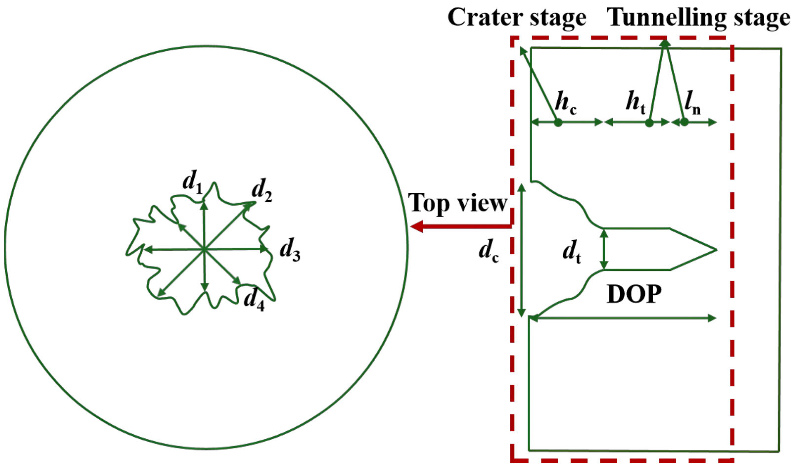
To accurately determine the dimensions of the craters on the concrete targets post-impact, a four-direction measurement method was employed to calculate the average dc. Specifically, using the geometric center of the crater as a reference, diameters were measured along four orientations: vertical (d2), horizontal (d4), 45° diagonal (d1), and 135° diagonal (d3). The arithmetic mean of these measurements was defined as the average crater diameter, as schematically illustrated in the top view Figure 6a. This approach effectively mitigates directional errors arising from crater irregularities, thereby yielding a more representative average value. Figure 6b presents a simplified schematic of the final hole profile of the target after projectile impact. The profile parameters include the crater diameter (dc), crater depth (hc), tunnel diameter (dt), tunnel depth (ht), nose length (ln), and depth of penetration (DOP).

2.3.1. Failure Mechanism

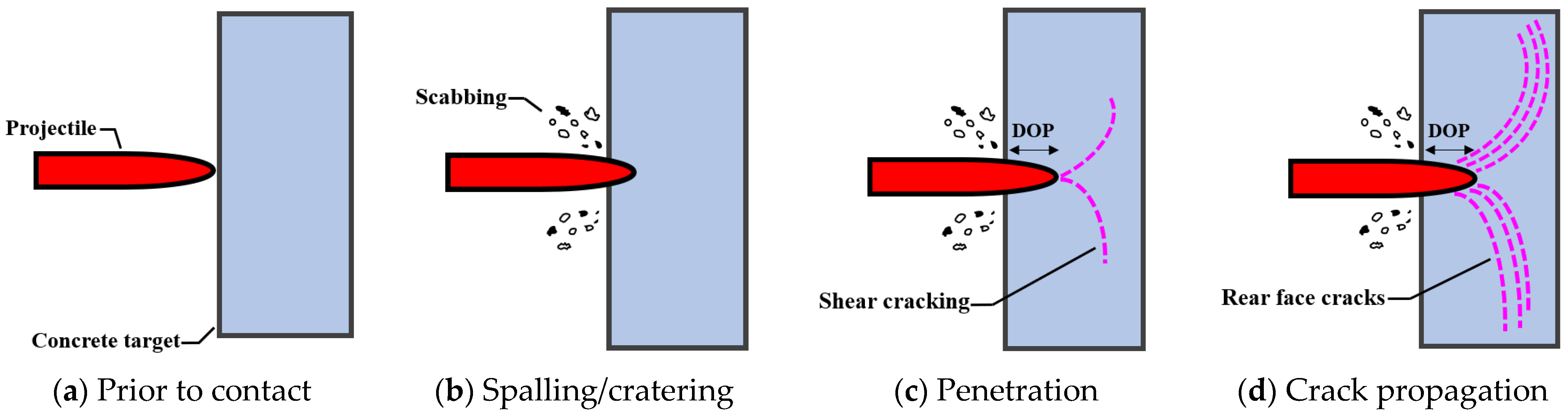
Figure 7 presents the typical damage evolution mechanism of a concrete target subjected to high-velocity projectile impact. This process can be elucidated through wave propagation theory. Upon high-speed impact, a localized high-strain-rate compaction zone is initially formed in the contact region. As the impact stress exceeds the dynamic compressive strength of the concrete, severe spalling occurs on the target surface, accompanied by the high-velocity ejection of numerous fragments. During the subsequent penetration phase, given that the tensile and shear strengths of concrete are significantly lower than its compressive strength, shear failure is induced, resulting in the formation of a funnel-shaped crater and the expansion of the perforation. This localized failure mode involves large-volume tensile-shear mixed damage and energy dissipation in the concrete, which must be properly represented in the numerical framework. To address this mechanism, To address this issue, this numerical model has undergone numerical calibration to capture the volumetric energy dissipation and time-dependent damage behavior of concrete under impact loading, thereby enabling the accurate reproduction of the formation of craters and the expansion of perforations.
As the projectile penetrates deeper, the surrounding material is crushed and laterally displaced, ultimately forming a cylindrical channel slightly larger than the projectile diameter. When shock waves propagate within the target and encounter interfaces, wave reflection and conversion occur. The incident compressive waves can be partially reflected as tensile waves at free surfaces or material interfaces and continue to propagate within the material. When these reflected tensile waves return to the front surface of the target, if their stress amplitude exceeds the dynamic tensile strength of the material, new cracks are readily initiated, further enlarging the initial crater and exacerbating damage to the front surface.
Based on the aforementioned wave propagation theory, the protective effect of the polyurea coating on the target is primarily manifested in the regulation of the shock wave transmission path and stress distribution. As observed in Figure 5, the PCT-2 and PCT-5 targets exhibited only a penetration hole smaller than the projectile diameter on the impact face during the penetration process. This is attributed to the fact that upon initial contact between the projectile and the target surface, a high-intensity compressive wave first acts on the polyurea layer. Characterized by excellent strain capacity and low wave impedance, the polyurea material absorbs a portion of the energy during the initial impact stage and delays the rapid transmission of stress waves into the concrete substrate, thereby reducing the degree of stress concentration in the concrete surface layer. After the projectile penetrates the polyurea, the coating undergoes instantaneous stretching due to inertia and rapidly rebounds to its original morphology, driven by its elastic recovery capability, forming a self-sealing effect that restricts the expansion of the damaged zone. Furthermore, when the compressive wave reaches the free surface and reflects as a tensile stress wave, the polyurea layer effectively attenuates the peak value of the reflected wave, reducing the risk of cratering and fragment scattering caused by tensile stresses. The high-speed camera results presented in Figure 4 further validate this mechanism: at 240 μs, the CT specimen exhibited extensive fragment scattering on its surface, whereas the reinforced target (PCT-5) showed significantly reduced fragmentation. Consequently, the high ductility of polyurea, combined with its favorable interfacial bonding performance, creates a dynamic crack-inhibiting layer that effectively constrains crack propagation and material spalling, thereby enhancing the overall impact integrity of the target.

2.3.2. Cratering Damage Features

Experimental results show that at an impact velocity of approximately 510 m/s, increasing the polyurea thickness from 0 mm (PCT-0) to 2 mm (PCT-2) and 5 mm (PCT-5) resulted in only a slight reduction in the depth of penetration (DOP) of the target, decreasing from 387 mm to 378 mm. It proves that the enhancement in penetration resistance provided by the polyurea layer is limited. Relevant studies have also noted that although polyurea exhibits excellent ductility under high strain rates [46], its compressive strength is significantly lower than that of concrete, rendering it ineffective in directly withstanding projectile kinetic energy to prevent longitudinal perforation. However, a more pronounced improvement was observed in terms of crater diameter (dc). The dc for the PCT-0 was 265 mm, whereas it decreased significantly to 224 mm for the PCT-5 target. This phenomenon is primarily attributed to the superior tensile strength and adhesive properties of polyurea, which effectively constrain crack propagation on the concrete surface and suppress the lateral ejection of fragments during impact. Furthermore, Li et al. [46] pointed out that the dispersion range of fragments is closely related to the crater diameter; thus, the restraining effect of polyurea on cracks and fragments directly contributes to the reduction of dc. Although polyurea has a limited influence on DOP, it demonstrates significant effectiveness in controlling surface damage expansion. These distinct protective characteristics provide critical guidance for the practical retrofitting design of concrete structures. The underlying mechanisms will be further explored in the subsequent section through numerical simulations.

3. Numerical Modelling

3.1. Finite-Element Models

To investigate the structural performance of both uncoated and coated concrete targets under high-velocity projectile impact, a full-scale coupled Finite Element (FE) and Smoothed Particle Hydrodynamics (SPH) numerical model was implemented in this study using the explicit dynamics analysis software LS-DYNA (Version R11.1, ANSYS Inc., Canonsburg, PA, USA), with LS-PrePost 4.5 employed for pre-processing and post-analysis. LS-DYNA was selected primarily for its robust multi-physics coupling capabilities, particularly its mature FE-SPH interaction algorithms, which are superior to other platforms for simulating transient impact events involving material fragmentation and splashing. Furthermore, its extensive library of specialized concrete damage models (e.g., K&C and HJC models) and high computational efficiency in large-scale explicit analysis make it uniquely suited for high-velocity penetration research [47,48].
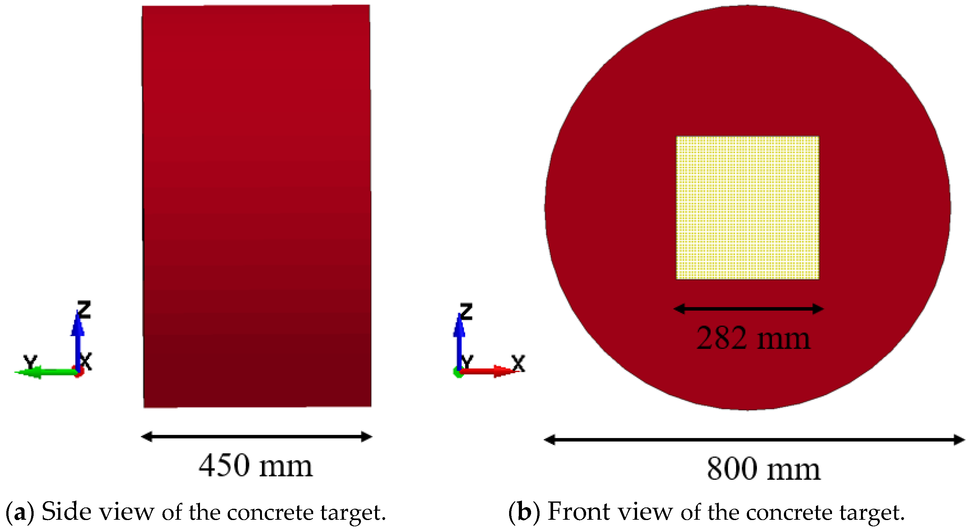
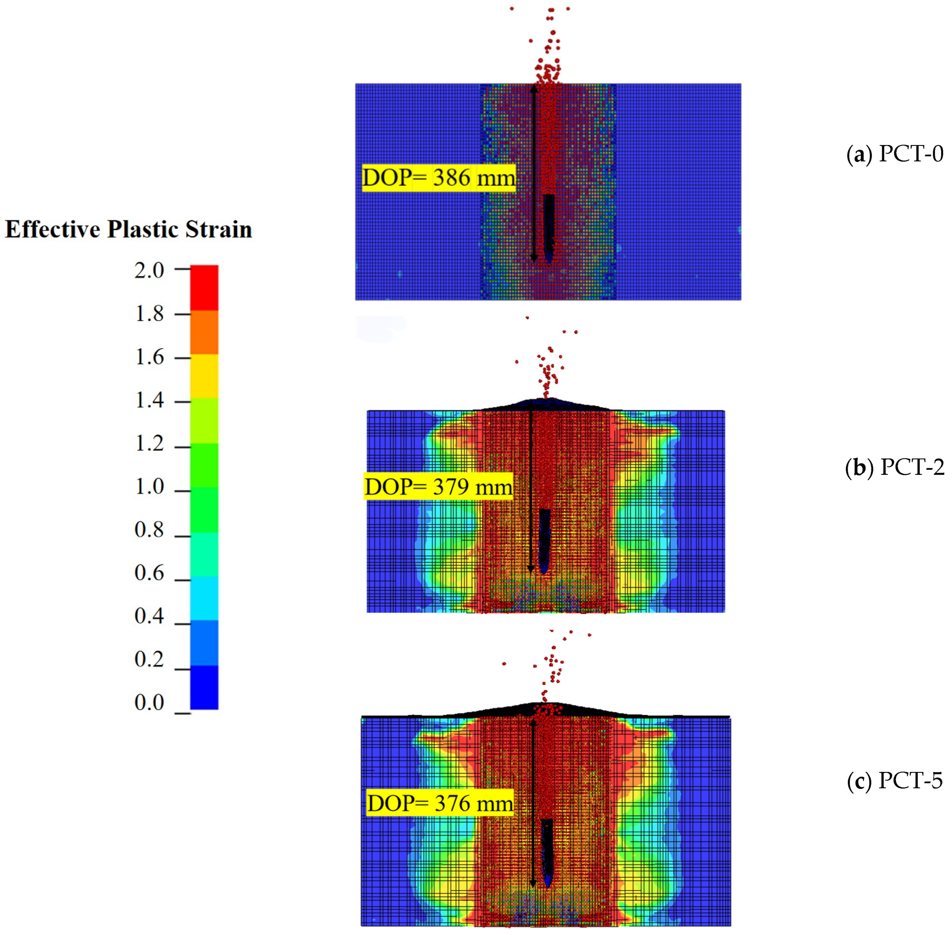
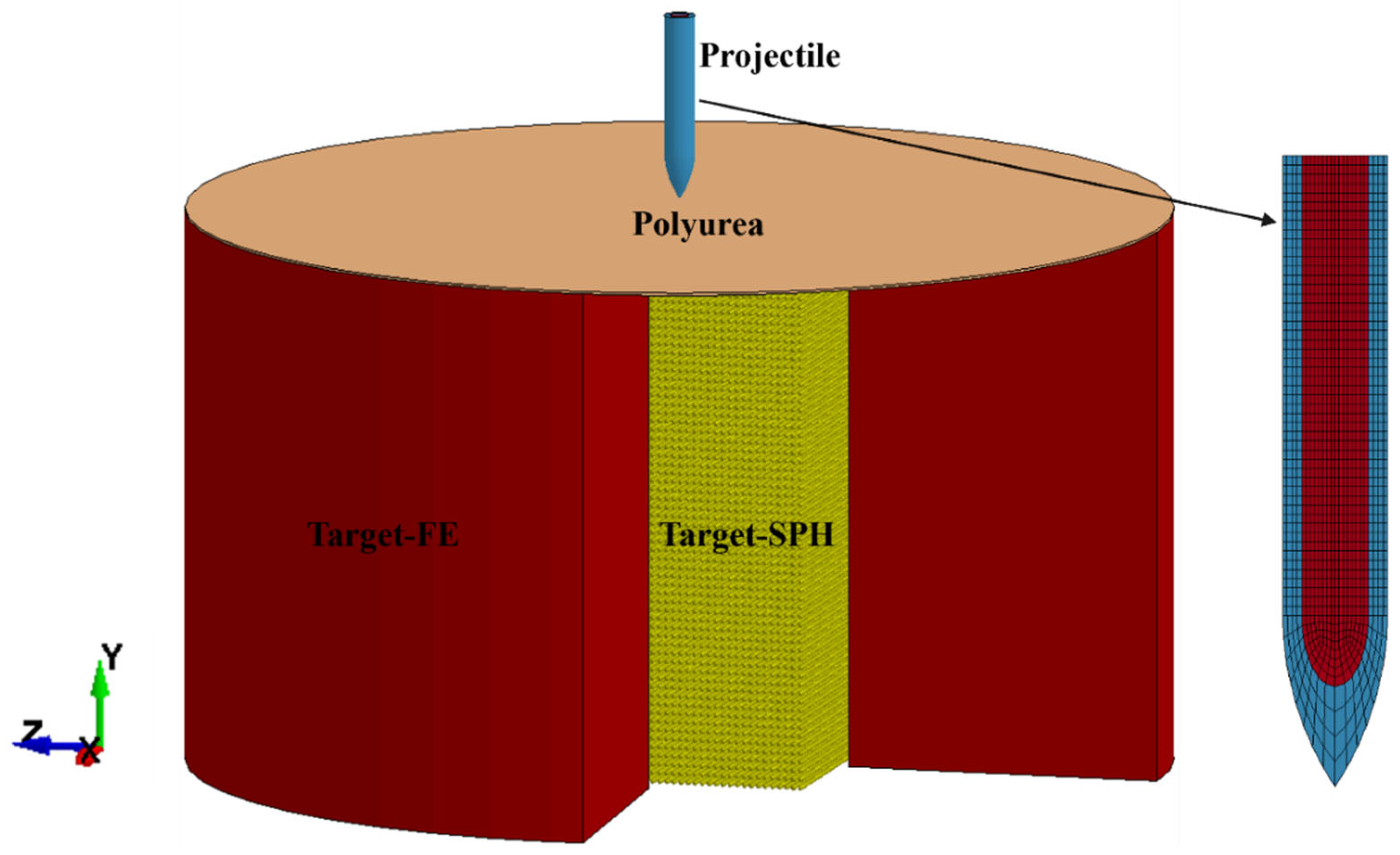
Figure 8 illustrates the finite element (FE) model developed in this study to simulate the projectile impact response of polyurea-coated concrete targets. Eight-node hexahedral solid elements with single-point integration were employed for discretization. To prevent non-physical “hourglass” modes inherent to low-order elements, Flanagan-Belytschko stiffness hourglass control (Type 5) with a coefficient of 0.1 was applied across all simulation scenarios. Furthermore, an entity-constrained Lagrangian formulation was adopted to ensure computational accuracy and mitigate mesh size dependency. To optimize overall computational efficiency while accurately capturing fragmentation phenomena, a coupled Smoothed Particle Hydrodynamics-Finite Element (SPH-FE) approach was utilized, leveraging the respective advantages of both methods. Based on the average crater diameter (dc) derived from the experimental data presented in Table 2, the dimensions of the SPH region were defined as 282 mm × 282 mm. The established model provides a robust foundation for subsequent simulations of the penetration process.

3.2. Material Models

3.2.1. Concrete Target

The cylindrical concrete target was subjected to fully fixed boundary conditions, with its top surface positioned vertically on a horizontal ground plane. As illustrated in Figure 9, the target has a diameter of 800 mm and a thickness of 450 mm. To balance computational efficiency and accuracy, a refined mesh was applied to the central impact zone, while a coarser mesh was utilized for the outer regions. The K&C concrete material model (*MAT_CONCRETE_DAMAGE_REL3, Mat_72R3) was employed in this study. This model effectively simulates the response behavior of concrete under complex loading conditions, proving particularly suitable for scenarios involving active/passive confining pressures and high strain rates, while offering high accuracy and computational efficiency [49,50]. The material model features an automatic parameter generation capability, enabling the derivation of a complete set of material parameters based solely on the unconfined compressive strength. According to Wu et al. [51], the default failure surface interpolation function within the K&C model performs well for all normal-strength concretes investigated; consequently, no parameter scaling is required for the failure surface interpolation functionality. Within the K&C model framework, three parameters are utilized in combination to govern damage evolution: b 1 controls the development of compressive damage, b 2 governs tensile damage progression, and w lz serves as a correlation parameter that also influences volumetric dilation. The expressions for calculating for b 1 and b 2 as proposed by Wu et al. [52], are formulated as follows:
b 1   =   0.34   h   +   0.79
b 2 = (   0.09 * w lz 2   0.98 * w lz + 3.06 ) ( 1 0.004 * f c 2 +   0.097 * f c 0.484 )  
In the equation, h represents the characteristic element size in feet; w lz denotes the aggregation size in feet (i.e., “LocWidth”), which should be assigned a value smaller than the element size in modeling; and f c is the unconfined compressive strength in ksi. As noted in study [51], the present experiment was not subjected to confining pressures from shear dilation, the default damage evolution parameters ( b 1 , b 2 and w lz ) generated by the model are adopted for the numerical simulations.
Furthermore, Omega (ω) is the parameter governing volumetric expansion (dilation) during damage evolution. For the unconstrained plain concrete target (PCT-0), the standard default value of =0.5 was adopted. However, for the polyurea-coated targets (PCT-2 and PCT-5), the polyurea layer exerts a strong passive confinement effect on the concrete substrate due to its high tensile strength and robust interfacial adhesion. This dynamic constraint significantly restricts the radial expansion and crack opening of the concrete under high-velocity impact. To accurately capture this confined volumetric compression behavior, the value of ω was appropriately increased to 0.75 for the coated targets, which aligns with calibration principles for constrained concrete (e.g., as discussed by Wu et al. [52], who highlighted the necessity of adjusting Omega under varying confinement conditions). The key parameters of the K&C model employed in this study are summarized in Table 3.

3.2.2. Projectile and Polyurea

The MAT_PIECEWISE_LINEAR_PLASTICITY model was applied to simulate the polyurea coating, with the failure strain defined as the yield criterion. This model captures the elastic or plastic behavior of the coating under blast loading and provides a failure criterion for analyzing fracture damage. The material density, elastic modulus, yield strength, and Poisson’s ratio were adopted from reference [31]. The parameters C and P, which are associated with strain-rate effects in the Cowper–Symonds model, were also obtained from [31]. As shown in Table 1, to capture the failure of polyurea, the material failure criterion and erosion were based on equivalent stress, with the tensile damage value of polyurea defined as 1.63. Preliminary simulations indicated that the current material parameters listed in Table 4 yielded favorable simulation results, showing good agreement with experimental data.
As illustrated in Figure 2, the projectile shell and core were modeled using the *MAT_JOHNSON_COOK and *MAT_PIECEWISE_LINEAR_PLASTICITY material models, respectively. The corresponding material parameters were derived from experimental data [53,54,55] and are detailed in Table 4. In the numerical simulations, a steel ogive-nosed projectile was launched at an impact velocity of 510 m/s to horizontally penetrate the centroid of the PCT. Regarding contact definitions, the *CONTACT_ERODING_NODES_TO_SURFACE algorithm was employed for the projectile–SPH particle interface. This selection was made because SPH particles are treated as discrete meshless nodes in the Lagrangian framework; this specific algorithm ensures robust interaction between the projectile’s rigid surface and the evolving ‘cloud’ of concrete particles as they are ejected during penetration. Meanwhile, the *CONTACT_ERODING_SURFACE_TO_SURFACE algorithm was adopted for the projectile–polyurea interface. This choice is essential for handling the extreme viscoelastic deformations and potential element failure of the coating. By using an ‘eroding’ formulation, the solver automatically updates the contact surfaces if the outer polyurea elements reach their failure criteria and are deleted, thereby preventing numerical ‘leakage’ where the projectile might unphysically pass through the distorted mesh. The entire penetration process was simulated using the explicit Lagrangian solver in LS-DYNA to ensure accurate capture of material failure and energy transfer under high-velocity impact conditions.

3.3. Validation of Numerical Models

3.3.1. Comparison of Damage Morphology

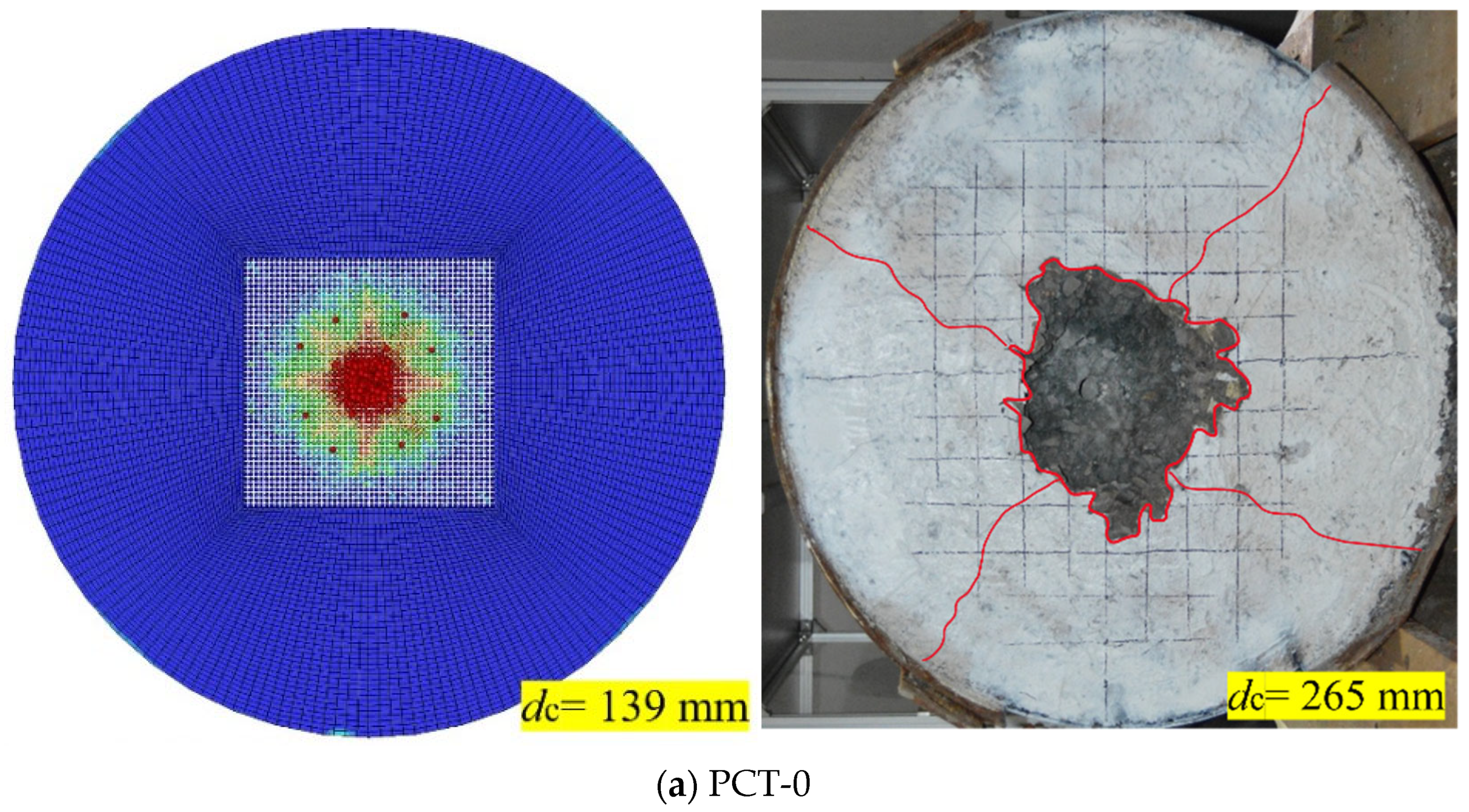
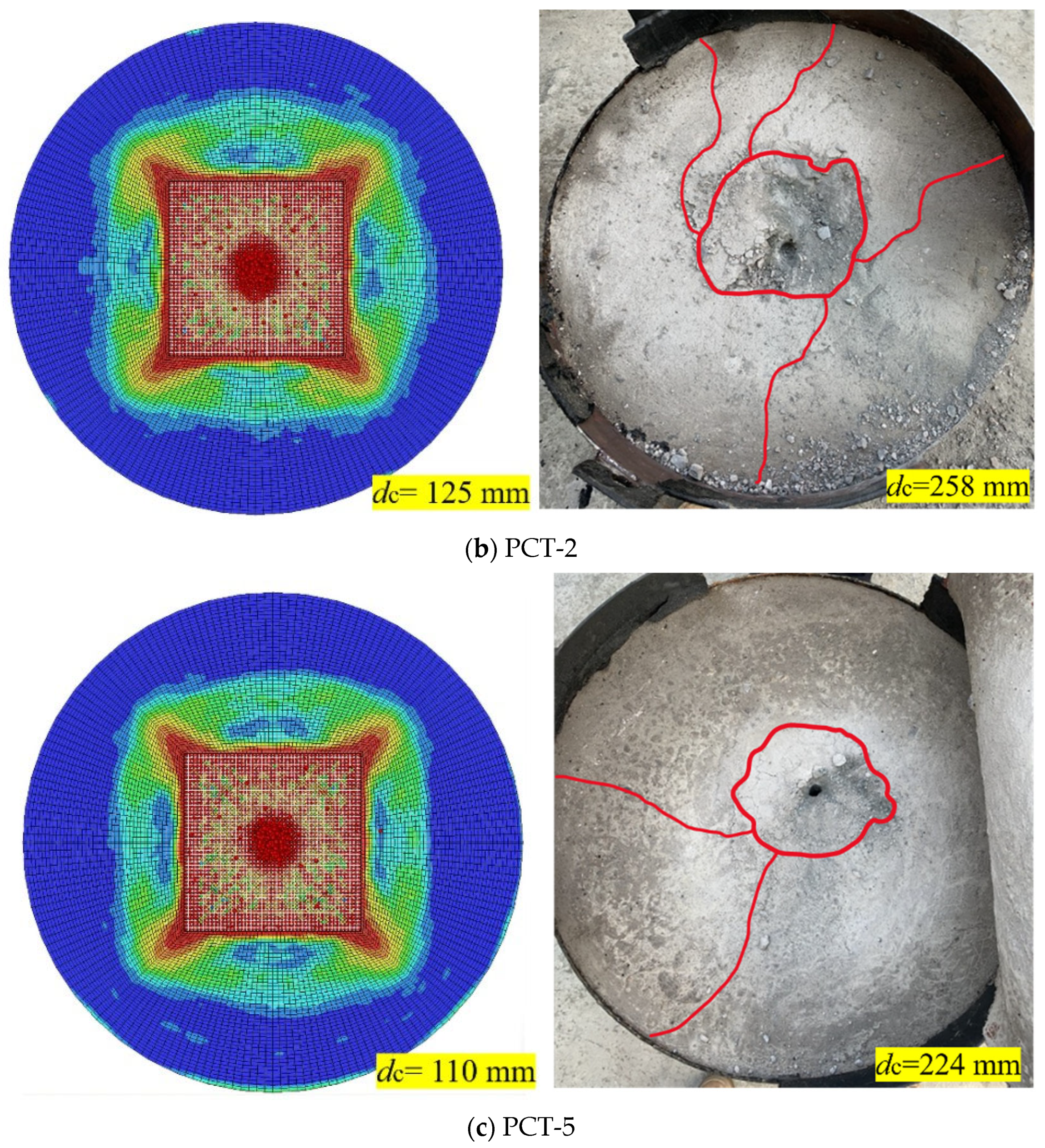
Figure 10 presents a comparative macroscopic view of the impact surfaces obtained from numerical simulations and experimental tests. Despite the inherent complexity involved in modeling concrete fracture, the simulation successfully captured the overall failure trends. Both experimental and numerical results indicate that the application of a polyurea coating significantly mitigates surface damage. As the coating thickness increased from 0 mm (PCT-0) to 5 mm (PCT-5), the spatial extent of the severe damage zone markedly decreased in both the physical specimens and the computed profiles. In the experiments (right column of Figure 10), the impact surface exhibited severe brittle spalling, characterized by large, irregular craters outlined in red and distinct radial cracks propagating toward the boundaries. In contrast, the numerical model (left column of Figure 10) employed effective plastic strain contours to characterize failure. Although the macroscopic homogenization approach did not explicitly generate discrete, long-range macro-cracks, the expanded high-strain regions (denoted in red and yellow) effectively represented localized material crushing and yielding. The experimentally measured crater diameter (dc) encompassed secondary surface spalling of the concrete cover, whereas the simulated damage boundary more accurately reflected the core crushing zone directly induced by the projectile’s kinetic energy. The SPH method inherently suffers from tensile instability and artificial viscous dissipation when handling crater edge spalling dominated by extreme mixed-mode tension and shear. Consequently, while the model yielded accurate predictions in the axial direction (compression-dominated, approximating Depth of Penetration), it provided somewhat conservative estimates in the radial direction (tension/shear-dominated, corresponding to crater diameter).

3.3.2. Quantitative Verification

Table 5 quantitatively compares the experimental and numerical results for the Depth of Penetration (DOP) and the crater diameter (dc). The numerical model demonstrates exceptional accuracy in predicting the DOP. For the PCT-0, PCT-2, and PCT-5 targets, the simulated DOP values are 386 mm, 379 mm, and 376 mm, respectively. Compared with the experimental measurements, the relative errors are merely 0.26%, 0.26%, and 0.53%, which are negligible. This high degree of consistency indicates that the proposed SPH-FE coupled algorithm, along with the calibrated constitutive models, accurately captures the primary energy dissipation mechanisms and the global dynamic resistance of the targets along the penetration trajectory. This phenomenon of diminishing returns faithfully reflects the protective mechanism of polyurea materials: as a hyperelastic material with low wave impedance, polyurea primarily inhibits concrete cracking through surface confinement effects, rather than directly resisting projectile penetration via high strength, as seen in high-hardness metal armors. The slight decrease in the DOP reduction trend for polyurea-reinforced targets with thicknesses increasing from 2 mm to 5 mm is attributed to the fact that polyurea’s contribution to DOP reduction is mainly manifested as interfacial resistance during the initial impact stage. Consequently, a thickness of 2 mm is sufficient to alter the initial contact conditions, whereas further increasing the thickness to 5 mm yields limited additional resistance during the stable, mid-to-late stages of projectile penetration.
Although the prediction of the Depth of Penetration (DOP) is highly accurate, the simulated crater diameter exhibits a significant underestimation, with relative errors ranging from 47.5% to 51.6%. Such discrepancies are a common and well-documented phenomenon in macroscopically homogeneous concrete simulations. In actual field tests, the formation of surface craters is primarily driven by the complex reflection of tensile stress waves and extensive, shallow spalling induced by the discreteness of aggregates and initial microcracks. Current macroscopic models treat concrete as a homogeneous medium, which inherently limits their capacity to fully reproduce the widespread and random brittle spalling observed on free surfaces. To bridge this gap, an extensive parametric sensitivity study was conducted over several months, involving numerous advanced numerical adjustments. These efforts included implementing FEM-SPH adaptive coupling models, performing fine-grained tuning of erosion criteria and interfacial contact parameters, and testing various SPH smoothing lengths to suppress artificial viscous dissipation. However, these iterations revealed a critical ‘trade-off’ phenomenon: while certain adjustments (such as significantly lowering the tensile cutoff pressure) could expand the simulated crater diameter, they invariably led to a detrimental loss of accuracy in predicting the Depth of Penetration (DOP), which is the primary metric for global protective performance. Consequently, the current configuration was maintained as the global optimum to ensure high-fidelity results for DOP (error < 1%) and internal energy evolution. Nevertheless, given that the primary objective of this study is to evaluate internal penetration resistance and macroscopic energy absorption, the deviation in surface cratering does not compromise the overall fidelity of the model.
Figure 11 shows the penetration mechanics mechanism through contour plots of effective plastic strain profiles. These contours clearly delineate the distinct failure modes between the plain concrete targets and the polyurea-coated targets. For the Polyurea-Coated Target (PCT) specimens (Figure 11b,c), the SPH particles effectively capture the significant upward bulging and severe tensile deformation of the polyurea layer at the impact face. This dynamically visualized deformation in the simulations explicitly demonstrates how the high-elasticity coating constrains the underlying concrete and dissipates kinetic energy through extensive plastic deformation, aligning with the theoretical protection mechanism.

4. Numerical Results and Discussion

4.1. Macro-Protective Performance

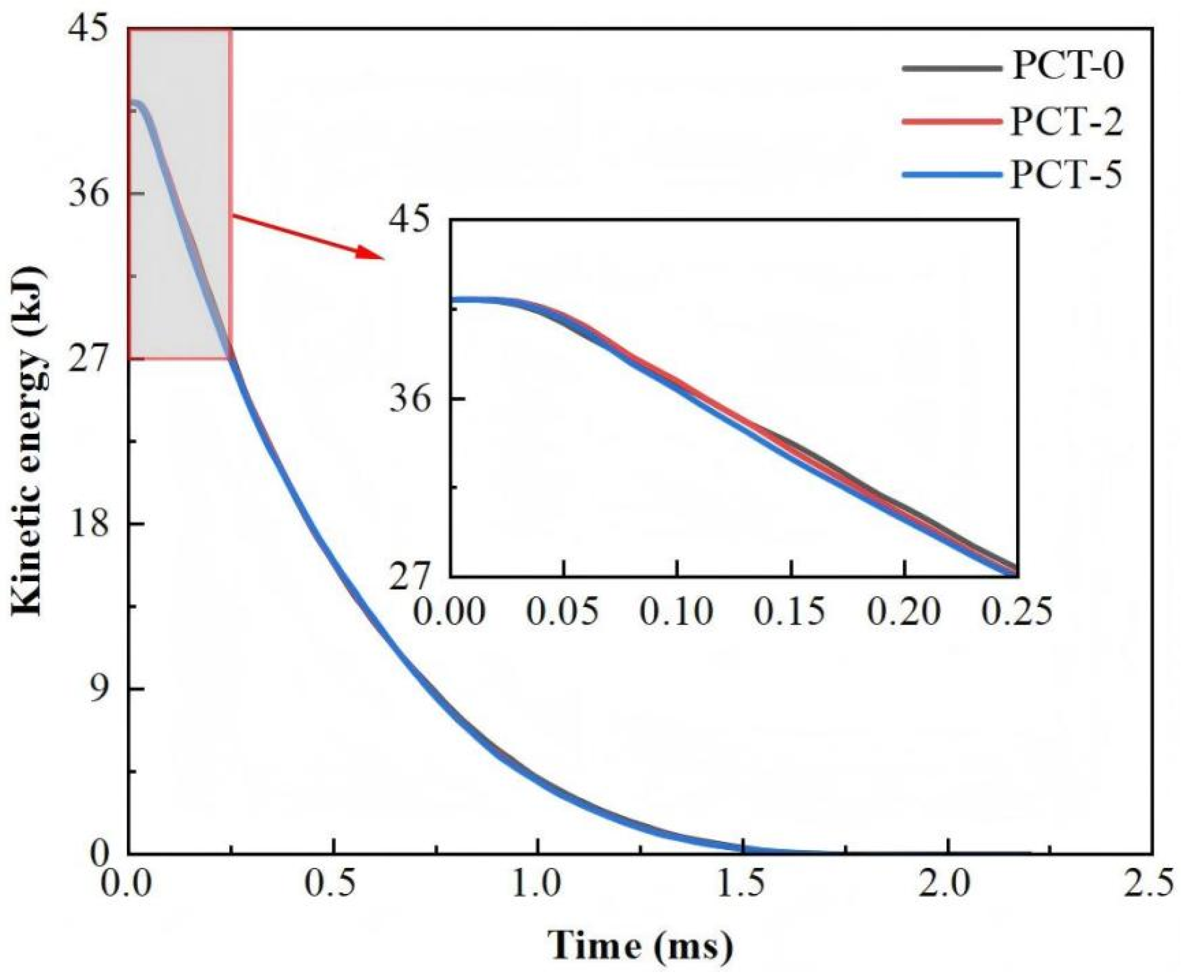
Following the validation of the macroscopic depth of penetration (DOP) and crater morphology, it is imperative to evaluate the dynamic energy dissipation process to further elucidate the protective efficiency of the polyurea coating. As illustrated in Figure 12, the macroscopic dynamic anti-penetration resistance of the target can be directly characterized by the temporal attenuation profile of the projectile’s kinetic energy. All curves exhibit a smooth exponential decay trend. In all cases, the initial kinetic energy of approximately 41 kJ was completely dissipated to zero within approximately 2.0 ms, indicating that the projectile was successfully intercepted by the target without perforation. The critical discrepancies in the energy decay rate were observed at the instant of impact. A locally magnified view of the initial phase (0–0.25 ms) reveals that the kinetic energy of the projectile impacting the PCT decreased more rapidly compared to that impacting the plain concrete target. This accelerated initial energy loss suggests that the polyurea coating instantaneously altered the impact impedance of the target surface. It provided an immediate dynamic confinement effect, compelling the projectile to perform additional work against the enhanced target during the early stage of penetration. While the rapid attenuation of kinetic energy offers macroscopic evidence of enhanced initial resistance, this global energy conversion is fundamentally governed by mesoscopic damage evolution and surface material fracture.

4.2. Meso-Scale Failure & SPH Evolution

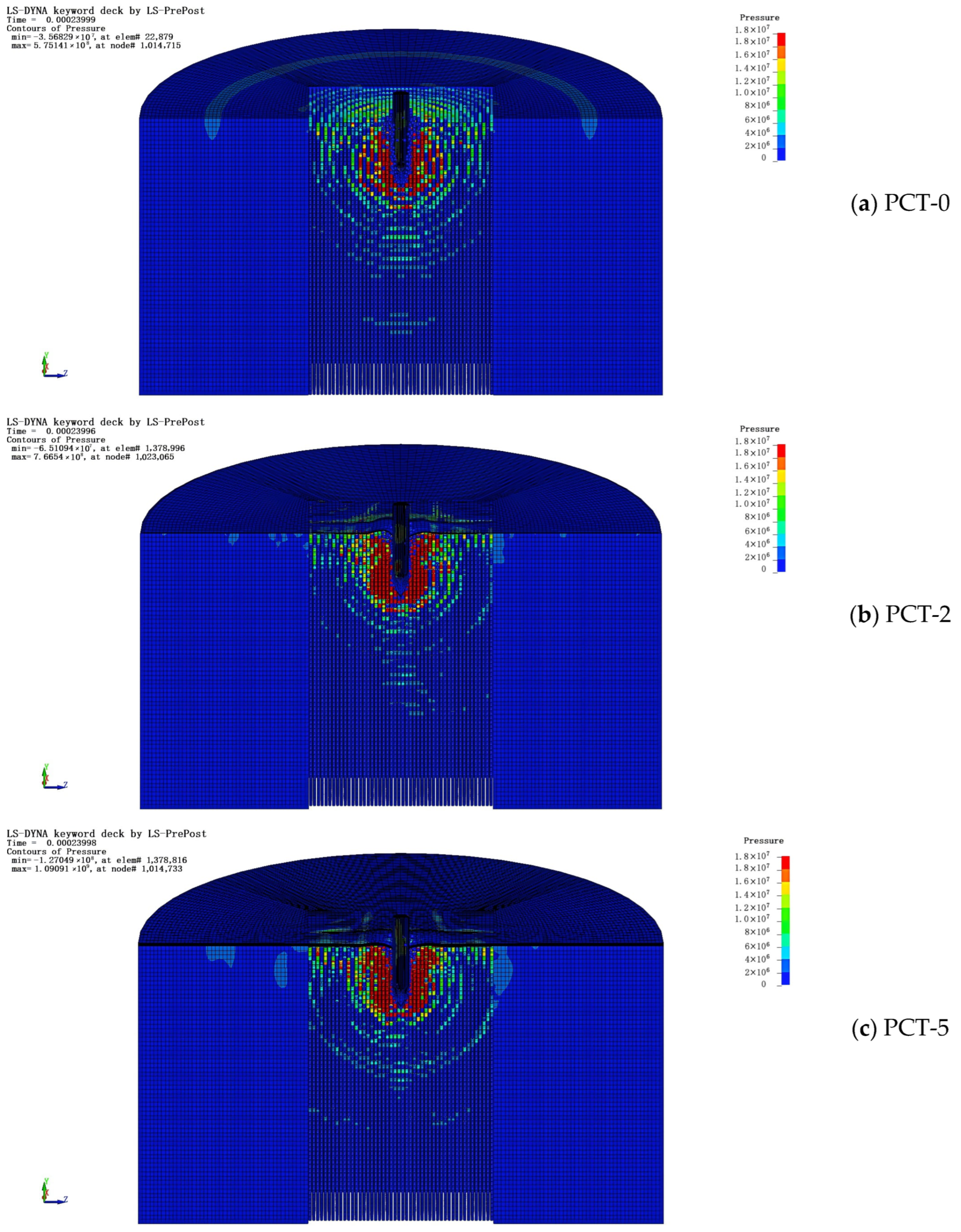
To fundamentally elucidate the mechanism by which the polyurea coating governs early-stage energy conversion and constrains concrete fragmentation, a detailed investigation into the mesoscopic kinematics of SPH particles and surface spalling behavior was conducted. Figure 13 presents detailed distributions of SPH particles in the cratering zone for different target configurations during the initial penetration stage (~0.24 ms), vividly depicting the spalling process of concrete under impact. As shown in Figure 13a, leveraging its mesh-free nature, the SPH algorithm effectively captures the transient crater formation and material ejection phenomena occurring at the onset of penetration. Under high-velocity impact, intense compressive stress waves propagate radially from the penetration zone; upon reaching the free surface above the target, these waves reflect, generating high-intensity tensile waves. Given the inherent tensile weakness (brittle characteristics) of concrete, surface particles rapidly lose cohesion with the matrix once the tensile limit is exceeded, resulting in the numerous freely scattering particles observed in the figure. In the uncoated PCT-0, this surface tensile spalling, induced by stress wave reflection, proceeds unhindered. A significant quantity of fragmented concrete particles, carrying substantial kinetic energy, detaches from the target. This not only leads to a macroscopically large crater diameter but also causes premature failure of the lateral confinement surrounding the penetration channel, thereby facilitating further projectile penetration.
In contrast, the PCT-2 and PCT-5 targets exhibited different interfacial meso-scale evolutionary characteristics (Figure 13b,c). Due to the presence of the polyurea coating, the original “concrete-air” free surface was replaced by a “concrete-polyurea” impedance-mismatched interface. When the reflected tensile wave attempted to spall the concrete surface, the highly tough polyurea layer demonstrated exceptional bridging and arresting capabilities. It not only physically contained the fragmented concrete particles, thereby preventing macroscopic spallation, but also recompacted these damaged zones, enabling them to continue contributing to frictional resistance and energy dissipation against the projectile. This meso-scale “fragment confinement” mechanism constitutes one of the core factors underlying the significantly enhanced macroscopic protective performance.

4.3. Mechanisms of Polyurea Reinforcement

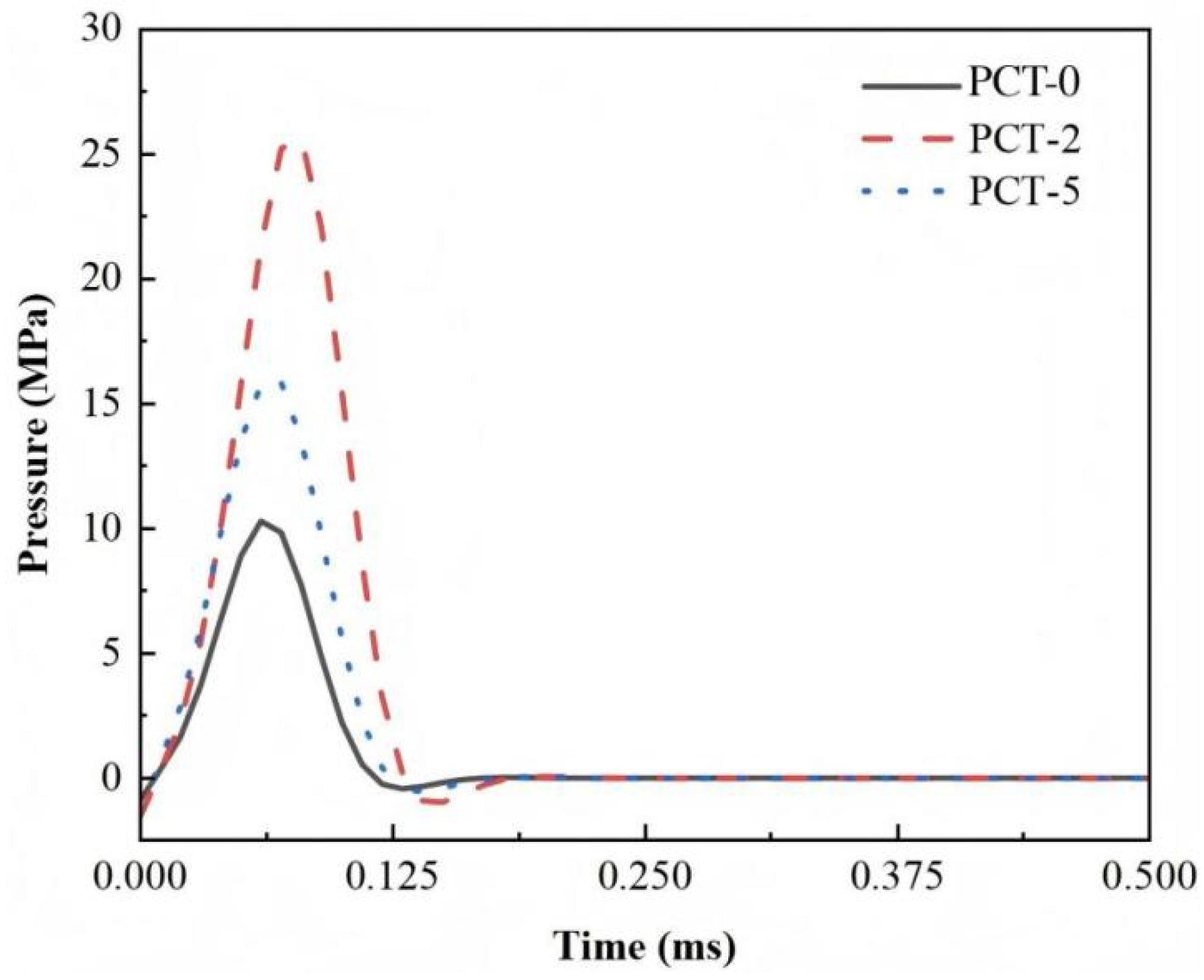
To extract reliable mechanical trends from the SPH simulations, a cluster of intact particles located 15 mm beneath the bullet impact axis was selected. This spatial averaging approach minimizes random errors induced by local numerical distortions. Subsequently, a low-pass filter was applied to the raw data to eliminate high-frequency numerical noise. Finally, the key parameters, including peak pressure (Pmax), rise time (tr), and impulse (I), were quantified to evaluate the protective efficacy of the polyurea coating. As illustrated in Figure 14 and Table 6, the polyurea coating significantly alters stress wave propagation within the concrete substrate. With increasing polyurea layer thickness, the peak pressure inside the target exhibits a nonlinear trend, initially increasing and subsequently decreasing.
When the polyurea thickness was 2 mm, the peak pressure increased significantly to 25.64 MPa. This phenomenon can be quantitatively elucidated by the theory of stress wave propagation across mismatched interfaces. The mechanical impedance (Z) of a material is defined as:
Z   =   ρ   c
where ρ is the material density and c is the longitudinal wave velocity. When the compressive stress wave propagates from the low-impedance polyurea (Zp) into the high-impedance concrete substrate (Zc), the stress transmission coefficient (T) at the interface is formulated as:
T   =   2   Z c Z c   +   Z p
Since Zc is significantly greater than Zp, the theoretical transmission coefficient T is strictly greater than 1.0. This mathematical relationship dictates an inevitable stress amplification at the interface. For the 2 mm coating, the wave transit time (τ = h/c, where h is thickness) is extremely short. The polymer is rapidly compacted before significant viscoelastic relaxation can occur, thereby acting as a high-stiffness dynamic boundary that dramatically forces the concrete to sustain higher compressive loads (25.64 MPa).
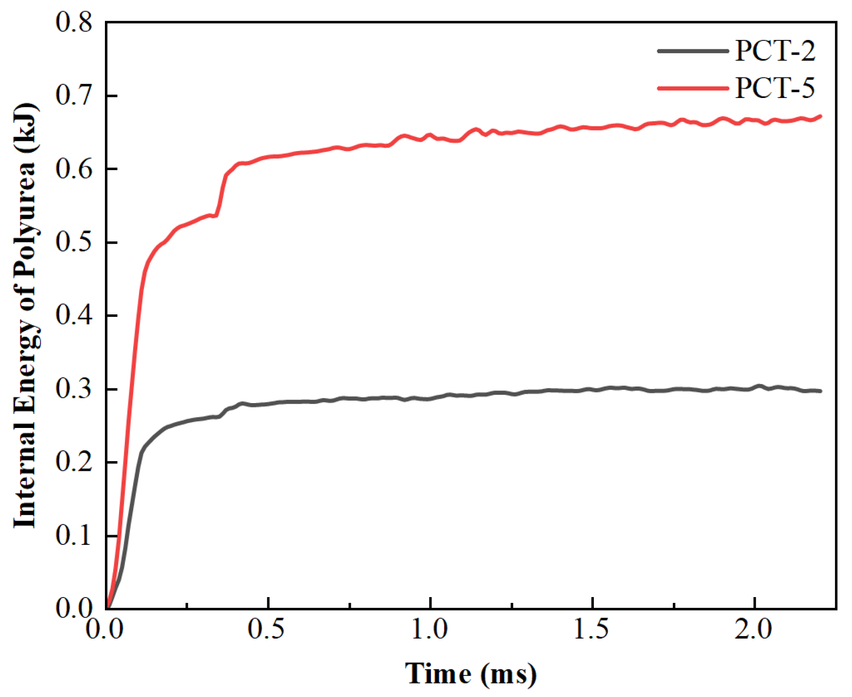
Interestingly, when the thickness was increased to 5 mm, the peak pressure dissipated to 15.84 MPa. The physical plausibility of this mechanism shift—triggered by a mere 3 mm thickness increment—lies in the competition between interfacial impedance amplification and cumulative wave attenuation. The 5 mm layer increases the wave propagation path by 1.5 times compared to the 2 mm layer. This extended transit time crosses the critical threshold required for the material’s viscoelastic relaxation. Consequently, the high-frequency components of the transient shock undergo severe geometric dispersion and viscoelastic damping. As supported by the internal energy data (Figure 15), the 5 mm layer absorbs ~650 J (more than double the ~300 J of the 2 mm layer). This indicates that in PCT-5, the thickness-dependent energy dissipation fundamentally outpaces the impedance-induced stress amplification, shifting the dominant mechanism from rigid confinement to wave dispersion.
When the polyurea thickness was 2 mm, the peak pressure increased significantly to 25.64 MPa. This indicates that the polyurea layer provided a dynamic confinement effect, which restricted the lateral expansion of the concrete and forced it to sustain higher compressive loads prior to local failure. Furthermore, the polyurea acted as a mechanical buffer, as evidenced by the delayed rise time (tr). Specifically, tr increased from approximately 60 μs in the plain concrete target (PCT-0) to about 80 μs in the polyurea-coated target (PCT-2). This extension effectively reduced the local loading rate and mitigated premature brittle fragmentation. Interestingly, when the thickness was increased to 5 mm, the peak pressure decreased to 15.84 MPa. This suggests that beyond a certain threshold, energy dissipation within the polyurea and wave dispersion effects become dominant, effectively shielding the deep concrete substrate from high-amplitude stress waves. Impulse data, obtained by time-integrating the pressure pulses, further elucidates the protective mechanism of the polyurea coating. As presented in Table 6, the impulse values for the coated targets were significantly higher than those for the plain concrete target, increasing from 0.58 MPa·ms to 1.59 and 0.98 MPa·ms, respectively. This demonstrates that the polyurea coating successfully altered the energy dissipation mode of the concrete matrix. The 2 mm polyurea coating exhibited a strong interface strengthening mechanism; the extremely high impulse transfer reflected severe confining pressure exerted by the coating on the substrate, thereby forcibly enhancing the upper limit of the concrete’s energy absorption capacity. In contrast, the 5 mm coating demonstrated a load-smoothing mechanism. Although its peak pressure dropped significantly compared to the 2 mm specimen, the impulse remained at a high level. This explains why, in the simulations, the 5 mm target did not achieve a further reduction in penetration depth; nevertheless, through a longer pulse duration and lower load amplitude, it effectively alleviated stress concentration within the concrete interior.
In summary, the polyurea coating creates a significant mechanical impedance mismatch at the interface between the low-impedance polymer and the high-impedance concrete substrate. This mismatch dictates the reflection and transmission of stress waves at the interface, resulting in a ‘peak-shaving and valley-filling’ energy redistribution. This mechanism transforms the highly destructive transient shock into a steady-state compression with lower energy density, thereby significantly enhancing the overall structural toughness while maintaining a consistent depth of penetration. Despite the limitations of the SPH model in capturing surface spalling-induced cratering, the pressure evolution at internal gauge points consistently validates the physical shielding effect governed by this impedance mismatch.
To elucidate the discrepancy between the macroscopic depth of penetration (DOP) and the local stress response, the evolution of internal energy within the polyurea layer was extracted and compared, as illustrated in Figure 15. The data reveal a fundamental shift in the protection mechanism governed by coating thickness. The 2 mm polyurea layer exhibits limited energy absorption capacity, with its internal energy stabilizing at approximately 300 J. Due to its thinness, PCT-2 is rapidly compressed, acting as a highly rigid constrained boundary that converts kinetic energy into intense dynamic compressive stress, thereby generating the observed maximum peak pressure in the concrete substrate (Pmax = 25.6 MPa). In contrast, the 5 mm polyurea layer functions as an efficient energy buffer. Its extended deformation path enables substantial viscoelastic dissipation and plastic work, absorbing approximately twice the internal energy of the 2 mm coating (ca. 650 J). This significant energy accumulation within the coating directly suppresses the shockwave transmitted to the substrate, effectively reducing the peak pressure to 15.8 MPa. Consequently, although PCT-2 and PCT-5 demonstrate similar overall anti-penetration performance, their underlying mechanisms differ fundamentally: PCT-2 resists penetration through high-intensity structural confinement, whereas PCT-5 mitigates impact forces via superior internal energy dissipation.

5. Conclusions

By integrating high-velocity penetration experiments with coupled FE-SPH numerical simulations, this study systematically investigates the reinforcement mechanism of polyurea coatings on concrete targets. The primary conclusions are summarized as follows:
(1)
Improvement in failure modes: The polyurea coating significantly mitigates surface damage in concrete. Unreinforced concrete targets subjected to high-velocity impact exhibit extensive brittle spalling and radial cracking. In contrast, the damaged area in reinforced targets is markedly reduced; the polyurea layer effectively captures and encapsulates high-velocity debris, thereby preventing secondary damage.
(2)
Advantages of numerical simulation: Polyurea coatings significantly reduced macroscopic surface damage, particularly in terms of crater diameter dc. While the uncoated PCT-0 exhibited a dc of 265 mm, the application of a 5 mm polyurea coating (PCT-5) reduced the crater diameter to 224 mm—a quantitative reduction of 15.5%. The simulation results demonstrate good agreement with experimental observations regarding macroscopic failure patterns.
(3)
Dynamic confinement and energy redistribution: The polyurea coating exhibits a pronounced “confining pressure” effect. A 2 mm-thick coating significantly enhances interfacial peak pressure and impulse transmission, thereby strengthening the concrete substrate. While a 5 mm-thick coating demonstrates a load-smoothing mechanism, effectively clipping the stress peak (down to 15.84 MPa) and shielding the deep substrate from stress concentration through energy dissipation and wave dispersion effects. Numerical analysis confirms that increasing coating thickness from 0 mm to 5 mm results in a progressive reduction of DOP from 387 mm to 378 mm. This ~2.3% decrease in DOP indicates that the coating’s primary role is energy redistribution rather than direct penetration resistance.
(4)
Summary of protection mechanisms: The primary contribution of polyurea reinforcement lies in enhancing the overall toughness of the structure rather than merely increasing its hardness. By transforming destructive transient impact loads into steady-state compressive stresses, polyurea coatings effectively preserve structural integrity while maintaining consistent penetration resistance depth.
(5)
Practical Engineering Design Recommendations: Based on the observed reduction in crater diameter (dc) and fragment suppression, a hybrid protection strategy is recommended for protective engineering. Polyurea should be deployed as a functional anti-spalling and containment layer rather than a primary barrier for reducing penetration depth. For facilities like military bunkers or blast walls, applying a ~5 mm coating to the impact or rear faces, combined with internal high-strength reinforcement, provides an optimal balance between depth control and fragment mitigation.
While the validated FE-SPH model provides a robust tool for mechanistic analysis, the authors acknowledge that the inherent heterogeneity of concrete targets and the limited sample size (one test per configuration) may introduce stochastic variations in metrics like crater diameter (dc). The current study focuses on characterizing the physical mechanisms—specifically the transition from dynamic confinement to wave dispersion—rather than establishing a purely statistical distribution of ballistic results.

Author Contributions

P.L.: Writing—original draft, Investigation, Formal analysis, Funding. Y.C.: Writing—original draft, Methodology, Software, Investigation. J.W.: Writing—review & editing, Investigation, Funding, Conceptualization. Y.W.: Investigation, Formal analysis, Data curation. All authors have read and agreed to the published version of the manuscript.

Funding

This work was supported by the Guangdong Provincial Young Top Talent Program (No. 2024TQ08C243), Shaanxi A&F Technology University Research Foundation (SJ2025-03, PT2024-001) and the Yangling Demonstration Zone Science and Technology Innovation and Promotion Bureau Research Program (2025CYFZ-19). Hebei Provincial Natural Science Foundation Chunhui Talent Project (Grant No. E2025202076).

Data Availability Statement

The data that support the findings of this study are available from the corresponding author upon reasonable request.

Conflicts of Interest

The authors declare no conflict of interest.

References

  1. Luccioni, B.; Isla, F.; Codina, R.; Ambrosini, D.; Zerbino, R.; Giaccio, G.; Torrijos, M.C. Experimental and numerical analysis of blast response of High Strength Fiber Reinforced Concrete slabs. Eng. Struct. 2018, 175, 113–122. [Google Scholar] [CrossRef]
  2. Shao, R.; Wu, C.; Liu, Z.; Su, Y.; Liu, J.; Chen, G.; Xu, S. Penetration resistance of ultra-high-strength concrete protected with layers of high-toughness and lightweight energy absorption materials. Compos. Struct. 2018, 185, 807–820. [Google Scholar] [CrossRef]
  3. Li, Y.; Aoude, H. Blast response of beams built with high-strength concrete and high-strength ASTM A1035 bars. Int. J. Impact Eng. 2019, 130, 41–67. [Google Scholar] [CrossRef]
  4. Zhong, R.; Zhang, F. Engineering high-performance cementitious matrices for improved projectile impact resistance with silane, micro fibrillated cellulose and fine calcined bauxite aggregate. Cem. Concr. Compos. 2023, 135, 104835. [Google Scholar] [CrossRef]
  5. Sui, X.; Ding, B.; Gu, J.; Zhou, Y.; Lin, Y.; Zhuang, K.; Xu, Y.; Jing, D.; Cai, J. Mechanical behavior of textile-reinforced engineered cementitious composites beams under accumulative impact. J. Build. Eng. 2024, 98, 111188. [Google Scholar] [CrossRef]
  6. Zhong, R.; Zhang, F.; Poh, L.H.; Wang, S.; Le, H.T.N.; Zhang, M.-H. Assessing the effectiveness of UHPFRC, FRHSC and ECC against high velocity projectile impact. Cem. Concr. Compos. 2021, 120, 104013. [Google Scholar] [CrossRef]
  7. Wang, J.; Ying, F. Research on the design method of flexural capacity of RC beams strengthen by ultra-high-performance concrete. Arch. Civ. Eng. 2024, 70, 487–507. [Google Scholar] [CrossRef]
  8. Liu, J.; Li, J.; Fang, J.; Su, Y.; Wu, C. Ultra-high performance concrete targets against high velocity projectile impact—A-state-of-the-art review. Int. J. Impact Eng. 2022, 160, 104080. [Google Scholar] [CrossRef]
  9. Liu, J.; Wu, C.; Su, Y.; Li, J.; Shao, R.; Chen, G.; Liu, Z. Experimental and numerical studies of ultra-high performance concrete targets against high-velocity projectile impacts. Eng. Struct. 2018, 173, 166–179. [Google Scholar] [CrossRef]
  10. Wu, H.; Fang, Q.; Peng, Y.; Gong, Z.M.; Kong, X.Z. Hard projectile perforation on the monolithic and segmented RC panels with a rear steel liner. Int. J. Impact Eng. 2015, 76, 232–250. [Google Scholar] [CrossRef]
  11. Choi, E.; Chung, Y.-S.; Park, K.; Jeon, J.-S. Effect of steel wrapping jackets on the bond strength of concrete and the lateral performance of circular RC columns. Eng. Struct. 2013, 48, 43–54. [Google Scholar] [CrossRef]
  12. Pham, T.M.; Hao, H. Review of concrete structures strengthened with FRP against impact loading. Structures 2016, 7, 59–70. [Google Scholar] [CrossRef]
  13. Bhatti, A.Q.; Kishi, N.; Tan, K.H. Impact resistant behaviour of RC slab strengthened with FRP sheet. Mater. Struct. 2011, 44, 1855–1864. [Google Scholar] [CrossRef]
  14. Yildirim, F.N.; Achintha, M. Glass–GFRP laminate: A proof of concept experimental investigation. J. Build. Eng. 2024, 85, 108733. [Google Scholar] [CrossRef]
  15. Dondish, A.; Li, L.; Melenka, G.W. Full-field deformation and failure analysis for compression after impact of carbon fibre reinforced polymer laminates. Compos. Struct. 2023, 323, 117469. [Google Scholar] [CrossRef]
  16. Liu, J.; He, Z.; Liu, P.; Wei, J.; Li, J.; Wu, C. High-velocity projectile impact resistance of reinforced concrete slabs with ultra-high performance concrete strengthening—A numerical study. Structures 2023, 52, 422–436. [Google Scholar] [CrossRef]
  17. Wei, J.; Li, J.; Wu, C.; Hao, H.; Liu, J. Experimental and numerical study on the impact resistance of ultra-high performance concrete strengthened RC beams. Eng. Struct. 2023, 277, 115474. [Google Scholar] [CrossRef]
  18. Xu, S.; Liu, Z.; Li, J.; Yang, Y.; Wu, C. Dynamic behaviors of reinforced NSC and UHPC columns protected by aluminum foam layer against low-velocity impact. J. Build. Eng. 2021, 34, 101910. [Google Scholar] [CrossRef]
  19. Liu, J.; Wu, C.; Li, C.; Dong, W.; Su, Y.; Li, J.; Cui, N.; Zeng, F.; Dai, L.; Meng, Q. Blast testing of high performance geopolymer composite walls reinforced with steel wire mesh and aluminium foam. Constr. Build. Mater. 2019, 197, 533–547. [Google Scholar] [CrossRef]
  20. Bohara, R.P.; Linforth, S.; Ghazlan, A.; Nguyen, T.; Remennikov, A.; Ngo, T. Performance of an auxetic honeycomb-core sandwich panel under close-in and far-field detonations of high explosive. Compos. Struct. 2022, 280, 114907. [Google Scholar] [CrossRef]
  21. Dharmasena, K.P.; Wadley, H.N.G.; Xue, Z.Y.; Hutchinson, J.W. Mechanical response of metallic honeycomb sandwich panel structures to high-intensity dynamic loading. Int. J. Impact Eng. 2008, 35, 1063–1074. [Google Scholar] [CrossRef]
  22. Hashemi, S.J.; Razzaghi, J.; Moghadam, A.S.; Lourenço, P.B. Cyclic testing of steel frames infilled with concrete sandwich panels. Arch. Civ. Mech. Eng. 2018, 18, 557–572. [Google Scholar] [CrossRef]
  23. Tian, S.; Yan, Q.; Du, X. Dynamic response and damage assessment of AAC masonry walls reinforced by spraying polyurea under blast load. Eng. Struct. 2025, 326, 119547. [Google Scholar] [CrossRef]
  24. Liu, J.; Liu, C.; Xu, S.; Li, J.; Fang, J.; Su, Y.; Wu, C. G-UHPC slabs strengthened with high toughness and lightweight energy absorption materials under contact explosions. J. Build. Eng. 2022, 50, 104138. [Google Scholar] [CrossRef]
  25. Zhu, H.; Ji, C.; Feng, K.; Tu, J.; Wang, X.; Zhao, C. Polyurea elastomer for enhancing blast resistance of structures: Recent advances and challenges ahead. Thin-Walled Struct. 2024, 200, 111938. [Google Scholar] [CrossRef]
  26. Tian, S.; Yan, Q.; Jiang, Y.; Du, X. Experimental and constitutive model investigation on the tensile mechanical properties of polyurea at wide strain-rate range. J. Build. Eng. 2024, 94, 109882. [Google Scholar] [CrossRef]
  27. Yue, Z.-Y.; Zhou, J.-N.; Wang, P.; Kong, X.-L.; Zhou, Y.-Z.; Chen, Y.-S.; Song, X.-Y.; Feng, F. Experimental study on the anti-blast performance of polyurea reinforced concrete arch structures. J. Build. Eng. 2023, 77, 107483. [Google Scholar] [CrossRef]
  28. Chen, Y.-S.; Wang, B.; Zhang, B.; Zheng, Q.; Zhou, J.-N.; Jin, F.-N.; Fan, H.-L. Polyurea coating for foamed concrete panel: An efficient way to resist explosion. Def. Technol. 2020, 16, 136–149. [Google Scholar] [CrossRef]
  29. Luo, R.; Liu, J.; Chen, Y.; Li, W.; Zhong, R.; Wei, J. Single and repeated impact response of normal reinforced concrete beams strengthened with polyurea coating—Experimental and numerical investigations. J. Build. Eng. 2025, 113, 114025. [Google Scholar] [CrossRef]
  30. Fallon, C.; Mcshane, G. Impact mitigating capabilities of a spray-on elastomer coating applied to concrete. Int. J. Impact Eng. 2019, 128, 72–85. [Google Scholar] [CrossRef]
  31. Benz, W.; Asphaug, E. Simulations of brittle solids using smooth particle hydrodynamics. Comput. Phys. Commun. 1995, 87, 253–265. [Google Scholar] [CrossRef]
  32. Smith, J.; Cusatis, G.; Pelessone, D.; Landis, E.; O’Daniel, J. Discrete modeling of ultra-high-performance concrete with application to projectile penetration. Int. J. Impact Eng. 2014, 65, 13–32. [Google Scholar] [CrossRef]
  33. Feng, J.; Sun, W.; Liu, Z.; Cui, C.; Wang, X. An armour-piercing projectile penetration in a double-layered target of ultra-high-performance fiber reinforced concrete and armour steel: Experimental and numerical analyses. Mater. Des. 2016, 102, 131–141. [Google Scholar] [CrossRef]
  34. Gingold, R.A.; Monaghan, J.J. Smoothed particle hydrodynamics: Theory and application to non-spherical stars. Mon. Not. R. Astron. Soc. 1977, 181, 375–389. [Google Scholar] [CrossRef]
  35. Lucy, L.B. A numerical approach to the testing of the fission hypothesis. Astron. J. 1977, 82, 1013–1024. [Google Scholar] [CrossRef]
  36. Randles, P.W.; Libersky, L.D. Smoothed particle hydrodynamics: Some recent improvements and applications. Comput. Methods Appl. Mech. Eng. 1996, 139, 375–408. [Google Scholar] [CrossRef]
  37. Xu, J.-X.; Liu, X.-L. Analysis of structural response under blast loads using the coupled SPH-FEM approach. J. Zhejiang Univ. Sci. A 2008, 9, 1184–1192. [Google Scholar] [CrossRef]
  38. Caleyron, F.; Chuzel-Marmot, Y.; Combescure, A. Modeling of reinforced concrete through SPH-FE coupling and its application to the simulation of a projectile’s impact onto a slab. Int. J. Numer. Meth. Biomed. Engng. 2011, 27, 882–898. [Google Scholar] [CrossRef]
  39. Hu, D.; Liu, C.; Xiao, Y.; Han, X. Analysis of explosion in concrete by axisymmetric FE-SPH adaptive coupling method. Eng. Comput. Int. J. Comput.-Aided Eng. 2014, 31, 758–774. [Google Scholar] [CrossRef]
  40. Yang, A.; Li, J.; Qu, H.; Pan, Y.; Kang, Y.; Zhang, Y. Numerical simulation of hypervelocity impact FEM-SPH algorithm based on large deformation of material. Preprints 2016, 2016100055. [Google Scholar] [CrossRef]
  41. Khayyer, A.; Shimizu, Y.; Gotoh, H.; Nagashima, K. A coupled incompressible SPH-Hamiltonian SPH solver for hydroelastic FSI corresponding to composite structures. Appl. Math. Model. 2021, 94, 242–271. [Google Scholar] [CrossRef]
  42. Karmakar, S.; Shaw, A. Response of R.C. plates under blast loading using FEM-SPH coupled method. Eng. Fail. Anal. 2021, 125, 105409. [Google Scholar] [CrossRef]
  43. Wang, Z.; Ma, D.; Suo, T.; Li, Y.; Manes, A. Investigation into different numerical methods in predicting the response of aluminosilicate glass under quasi-static and impact loading conditions. Int. J. Mech. Sci. 2021, 196, 106286. [Google Scholar] [CrossRef]
  44. Kennedy, R.P. A review of procedures for the analysis and design of concrete structures to resist missile impact effects. Nucl. Eng. Des. 1976, 37, 183–203. [Google Scholar] [CrossRef]
  45. Chen, X.W.; Li, Q.M. Deep penetration of a non-deformable projectile with different geometrical characteristics. Int. J. Impact Eng. 2002, 27, 619–637. [Google Scholar] [CrossRef]
  46. Li, Q.M.; Reid, S.R.; Wen, H.M.; Telford, A.R. Local impact effects of hard missiles on concrete targets. Int. J. Impact Eng. 2005, 32, 224–284. [Google Scholar] [CrossRef]
  47. Zhu, G.; Wu, B.; Wang, Z. Experimental study of polyurea-reinforced honeycomb targets under sequential penetration and blast. Compos. Part B Eng. 2025, 307, 112904. [Google Scholar] [CrossRef]
  48. Hallquist, J.O. LS-DYNA Keyword User’s Manual, Version 970; Livermore Software Technology Corporation (LSTC): Livermore, CA, USA, 2007; pp. 299–800.
  49. Crawford, J.E.; Wu, Y.; Choi, H.-J.; Magallanes, J.M.; Lan, S.J.K.; Case, G. Use and Validation of the Release III K&C Concrete Material Model in LS-DYNA; TR-11-36.6; Karagozian & Case: Glendale, CA, USA, 2012. [Google Scholar]
  50. Zhang, F.; Wu, C.; Zhao, X.-L. Numerical modeling of concrete-filled double-skin steel square tubular columns under blast loading. J. Perform. Constr. Facil. 2015, 29, B4015002. [Google Scholar] [CrossRef]
  51. Wu, Y.; Crawford John, E. Numerical Modeling of Concrete Using a Partially Associative Plasticity Model. J. Eng. Mech. 2015, 141, 04015051. [Google Scholar] [CrossRef]
  52. Wu, Y.; Crawford, J.E.; Lan, S. Validation studies for concrete constitutive models with blast test data. In Proceedings of the 13th International LS-DYNA Users Conference, Livermore, CA, USA, 8–10 June 2014. [Google Scholar]
  53. He, L.L.; Chen, X.W.; Wang, Z.H. Study on the penetration performance of concept projectile for high-speed penetration (CPHP). Int. J. Impact Eng. 2016, 94, 1–12. [Google Scholar] [CrossRef]
  54. Liang, B. Research on the Penetration and Blasting Damage of Concrete Slab Under Anti-Hard-Target Warhead. Doctoral Dissertation, China Academy of Engineering Physics, Beijing, China, 2009. (In Chinese) [Google Scholar]
  55. Geng, B. Study on the Mechanical Behavior of Materials Used in Earth Penetrator Weapon; University of National Defense Science and Technology: Changsha, China, 2010. [Google Scholar]
Figure 1. The uniaxial compression testing results of concrete.
Buildings 16 02076 g001
Figure 2. Projectile dimension.
Buildings 16 02076 g002
Figure 3. Schematic diagram of high-speed projectile impact on concrete target.
Buildings 16 02076 g003
Figure 4. High-speed camera sequences illustrating the typical projectile penetration process and fragment ejection at an impact velocity of ~510 m/s: (a) PCT-0; (b) PCT-5.
Buildings 16 02076 g004
Figure 5. Macroscopic damage morphologies of the target front faces after high-velocity projectile impact.
Buildings 16 02076 g005
Figure 6. Schematic diagrams of damaged thick concrete targets after projectile impact.
Buildings 16 02076 g006
Figure 7. Damage mode of plain concrete target under projectile impact loads.
Buildings 16 02076 g007
Figure 8. Finete element model of polyurea coated concrete target against projectile impact.
Buildings 16 02076 g008
Figure 9. Geometric model and dimensions of the concrete target used in the numerical simulations.
Buildings 16 02076 g009
Figure 10. Comparison of target damages between numerical and test results.
Buildings 16 02076 g010aBuildings 16 02076 g010b
Figure 11. Macro validation and mesoscopic damage distribution.
Buildings 16 02076 g011
Figure 12. Time histories of projectile kinetic energy for targets.
Buildings 16 02076 g012
Figure 13. Comparison of particle dispersion states on the target surface (t = ~0.24 ms).
Buildings 16 02076 g013
Figure 14. Pressure time history curve of Non-failed SPH particles.
Buildings 16 02076 g014
Figure 15. Internal energy time history curve of the polyurea layer.
Buildings 16 02076 g015
Table 1. Material Properties of LINE-X 350 Polyurea.
Density (g/cm3)Elastic Modulus (MPa)Tensile Strength (MPa)Failure Strain
1.0820122.391.63
Table 2. High-velocity impact testing data.
SpecimenImpact Velocity (m/s) d c   (mm)DOP (mm)
PCT-0513265387
PCT-2508258380
PCT-5508224378
Table 3. Key inputs for Mat_72R3.
Model ParameterValue
LocWidth25.4 mm
b 1 1.6
b 2 1.35
Omega (PCT-0)0.5
Omega (PCT-0&PCT-5)0.75
Table 4. Material parameter of polyurea and projectile.
Component/Material ModelParameterValue
Polyurea Coating
(MAT_PIECEWISE_LINEAR_PLASTICITY)
ρ/(kg‧m−3)1100
Young’s Modulus (MPa)250
Poisson’s Ratio0.47
Yield Stress (MPa)6
Tangent Modulus (MPa)20
β0
C0.73
P6.49
Failure Strain0.85
VP0
Projectile Casing
(MAT_JOHNSON_COOK)
Shear Modulus (GPa)82
Young’s Modulus (GPa)210
Poisson’s Ratio0.28
a1.539 × 109
b4.77 × 108
n0.18
c0.012
m1.0
Failure Stress (GPa)−2
D 1 0.15
D 2 0.72
D 3 1.66
*EOS_GRUNEISENC4596
S 1 1.357
γ1.71
A0.43
Projectile Backfill
(*MAT_PIECEWISE_LINEAR_PLASTICITY)
Young’s Modulus (GPa)10
Poisson’s Ratio0.45
Yield Stress (MPa)60
Tangent Modulus (GPa)0.1
Failure Strain3
Table 5. Comparison of experimental and numerical results.
PCT-0 PCT-2PCT-5
TestNumericalErrorTestNumericalErrorTestNumericalError
DOP (mm)3873860.26%3803790.26%3783760.53%
dc (mm)26513947.5%25812551.6%22411049.1%
Table 6. Comparison of pressure pulse characteristic values.
Target TypePmax (MPa)tr (μs)I (MPa·ms)Relative Change
PCT-010.28~600.58standard value
PCT-225.64~801.59pressure build-up
PCT-515.84700.98pressure drop
Note: Pmax is peak pressure; tr is the pulse rise time, I is the impulse.
Disclaimer/Publisher’s Note: The statements, opinions and data contained in all publications are solely those of the individual author(s) and contributor(s) and not of MDPI and/or the editor(s). MDPI and/or the editor(s) disclaim responsibility for any injury to people or property resulting from any ideas, methods, instructions or products referred to in the content.