Article

Protecting RC Plate Subjected to Combined Effect of Blast and Fragments with ECC

Key Laboratory of Urban Security and Disaster Engineering of Ministry of Education, Beijing University of Technology, Beijing 100124, China
*
Author to whom correspondence should be addressed.
Buildings 2026, 16(10), 2005; https://doi.org/10.3390/buildings16102005
Submission received: 29 March 2026 / Revised: 11 May 2026 / Accepted: 18 May 2026 / Published: 20 May 2026

Abstract

To improve the resistance of reinforced concrete (RC) plates against combined blast and fragment loading, the effectiveness of engineered cementitious composite (ECC) protective layers was investigated. Existing studies have mainly focused on single loading conditions, while the coupled effects and the influence of key ECC design parameters remain insufficiently understood. In this study, validated numerical models were developed to examine the effects of ECC thickness, compressive strength, and protective configuration on the structural response. The results show that ECC protection significantly mitigated damage and deformation, identifying thickness as the dominant factor. As the ECC thickness increased, the cratering area decreased from approximately 650,000 mm2 to nearly zero, and the central displacement was reduced from 32.2 mm to 18.7 mm (≈42% reduction). In contrast, increasing compressive strength from C30 to C70 resulted in only a limited reduction in displacement (26.6 mm to 23.9 mm). Regarding configuration, double-sided protection further reduced displacement to 19.7 mm (≈39% reduction) and effectively suppressed damage on both surfaces. Overall, the protective performance of ECC layers is governed primarily by thickness and configuration rather than compressive strength. These findings provide quantitative guidance for the design of ECC-strengthened RC structures under combined blast and fragment loading.

1. Introduction

Blast events arising from industrial accidents, terrorist attacks, and military conflicts can cause severe damage to conventional concrete structures [1,2,3], thereby compromising structural integrity and occupant safety. Effective protective measures are therefore required for critical structures and essential infrastructure. Blast loading is characterized by high impulsiveness, strong nonlinearity, and high intensity, and it typically affects structures through the combined action of blast and high-velocity fragments [4], resulting in severe damage such as concrete cratering, reinforcement buckling, local perforation, and even global structural failure [5,6,7]. In this context, reinforced concrete (RC) plates, which are widely employed in critical infrastructure systems, have attracted considerable research attention due to their broad engineering applications and the increasing demand for enhanced mechanical performance and sustainability, especially in the development of recycled aggregate concrete materials [8,9,10].
Although traditional reinforced concrete (RC) plates possess inherent load-bearing and deformation capacities, their blast resistance remains insufficient under combined blast and fragment loading [11,12,13]. Brittle failure is likely to occur under such extreme conditions [14,15,16], and the energy dissipation capacity of RC structures is inherently limited [17,18,19]. Previous studies indicated that the failure modes and dynamic response of RC slabs under blast and impact loading were strongly influenced by reinforcement configurations, including reinforcement ratio, bar diameter, and distribution [20,21,22]. Variations in these parameters were shown to significantly affect crack propagation, deformation characteristics, and failure patterns, such as spalling, scabbing, and flexural or punching failure modes [23,24,25]. However, under extreme loading conditions, even when optimized reinforcement configurations were adopted, the intrinsic brittleness and limited energy dissipation capacity of RC structures were still difficult to overcome [24].
Therefore, enhancing the blast resistance and improving the damage tolerance of RC plates have become urgent engineering challenges. In recent years, engineered cementitious composites (ECC), which exhibit high ductility and superior energy absorption capacity [26,27,28], have demonstrated substantial potential in blast resistance [29,30,31], penetration mitigation, and blast protection. The associated dissipation of blast energy [32,33,34] enables ECC to effectively delay damage progression. When combined with the RC plate, ECC contributes to the formation of an efficient composite protective system, thereby enhancing the overall blast resistance of the structural member.
A considerable body of research has examined the mechanical behavior and blast response of ECC materials. Victor C. Li and his colleagues reported that ECC develops a characteristic pattern of multiple microcracks under tensile loading and exhibits pronounced strain-hardening behavior [35,36,37,38], thereby substantially enhancing structural ductility. Maalej and Li further observed that, under impact or blast loading, an ECC layer can effectively reduce stress concentrations and delay crack initiation and propagation in RC structural members [39,40,41]. In addition, experimental and numerical studies have demonstrated that the application of ECC as an external strengthening layer significantly improves the blast resistance and energy absorption capacity of RC structures [42,43,44,45]. However, most existing studies have focused on single blast loading or idealized impact conditions, while systematic investigations under representative cased charge scenarios remain limited. In particular, under the combined action of blast waves and dispersed fragments, the dynamic response of ECC-protected RC plates has not been sufficiently understood. The effects of key ECC parameters, including thickness, strength level [46,47,48], and configuration, on displacement response, energy dissipation mechanisms, and failure modes have not been fully quantified, and the underlying relationships among these response characteristics remain unclear. This lack of comprehensive understanding has hindered the wider application of ECC-based protective systems in practical engineering.
In this study, a representative cased charge detonation scenario was considered, and numerical models of RC plates subjected to combined blast and fragment loading were established and validated against experimental data. Based on the validated model, the effectiveness of ECC protective layers was systematically investigated. A parametric study was subsequently conducted to evaluate the influence of key governing factors, including ECC thickness, compressive strength, and configuration, on the structural response and damage characteristics of the RC plate. The results of this study provide new insights into the dynamic response and energy dissipation mechanisms of ECC-protected RC plates under combined loading conditions, and offer a rational basis for the design of protective structures in extreme environments.

2. Protection Performance of RC Plate with ECC Layer Subjected to Combined Loading of Blast and Fragments

2.1. Numerical Model

Due to the high risks and safety concerns associated with experimental investigations involving combined blast and fragment loading, as well as the constraints imposed by testing site conditions, the experimental process was difficult to control precisely and showed poor repeatability. To avoid unnecessary risks, reduce experimental costs, and ensure the continuity of the research, numerical simulations were conducted in this study using ANSYS/LS-DYNA (18.0) to reproduce the response of an RC plate subjected to combined blast and fragment loading.
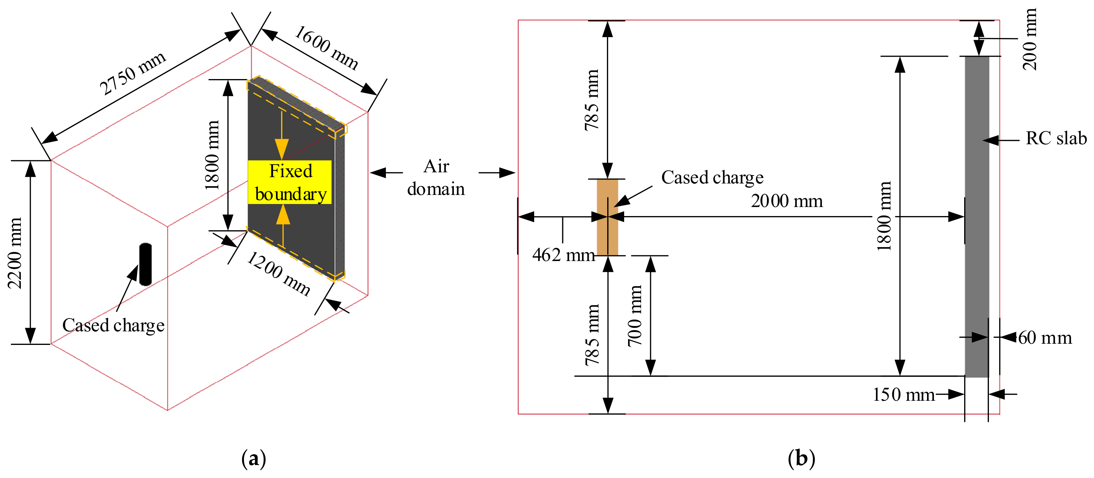
RC structural members experience severe damage under the combined loading of blast and fragments; however, the application of a protective layer to their surface can effectively mitigate the extent of damage. In this study, a numerical model of an ECC-protected RC plate subjected to coupled blast–fragment loading was developed in LS-DYNA, as illustrated in Figure 1. The air domain measured 2750 mm in length, 1600 mm in width, and 2200 mm in height, while the RC plate measured 1800 mm × 1200 mm × 150 mm. The ECC protective layer had the same length and width as the RC plate and had a thickness of 20 mm. Fixed boundary conditions were applied using the keyword BOUNDARY_SPC_SET over a 100 mm region along the short edges of the RC plate and a 100 mm region along the rear edge in the longitudinal direction. The air and charge were modeled using Eulerian elements, whereas the RC plate, ECC layer, and charge casing were modeled using Lagrange elements. Interaction between the Eulerian and Lagrangian domains was achieved through CONSTRAINED_LAGRANGE_IN_SOLID. Non-reflecting boundaries were imposed on the air domain using BOUNDARY_NON_REFLECTING. Considering the bonding strength between the ECC protective layer and the RC plate, a shared-node approach was adopted to define the interfacial interaction, thereby ensuring full composite action between the two materials. Because the cased charge was cylindrical, the keyword INITIAL_VOLUME_FRACTION_GEOMETRY was used to embed a 5 kg cylindrical TNT charge within the air domain, which was subsequently detonated at its mid-height using INITIAL_DETONATION. In the experiment, the total mass of the charge casing was 10 kg. Following detonation, the average fragment mass was approximately 3.0 g, with fragments smaller than 3.0 g accounting for about 80% of all fragments. The maximum and minimum fragment masses were 28 g and 0.02 g, respectively. To reproduce the experimental fragmentation characteristics as accurately as possible in the numerical simulation, a segmented meshing strategy was adopted for the charge casing. Specifically, a mesh size of 2 mm was assigned to the 300 mm central region along the axial direction, while a mesh size of 3 mm was used in the two adjacent 65 mm regions. In the thickness direction, a mesh size of 2 mm was employed, with a total of four element layers. The resulting numerical model consisted of approximately 1.5 million elements. Under blast loading, portions of the RC plate and ECC layer could undergo material failure; therefore, MAT_ADD_EROSION was used to remove eroded elements during the simulation, with maximum principal strain limits of 0.01 for the RC and 0.2 for the ECC layer [49]. To reduce computational cost, local mesh refinement was applied to both the RC plate and the ECC layer, and a mesh size of 1 mm was assigned to a central region measuring 600 mm in length, while a coarser mesh size of 2 mm was used elsewhere.

2.2. Material Models

The main materials involved in the numerical modeling of the cased charge explosion test included explosives, No. 45 steel, air, concrete, and reinforcing steel. The corresponding material parameters are briefly described below.

2.2.1. ECC

In LS-DYNA, a variety of material models were available for numerical simulation of concrete, such as the No. 72 K&C model, the No. 111 HJC model, the No. 159 CSCM model, and the No. 272 RHT model. Numerous researchers have conducted extensive studies on these models [50,51]. Previous studies [52,53] showed that the K&C model #72 performed well in simulating the damage response of concrete under various conditions. Therefore, in this study, the K&C model in LS-DYNA was adopted to simulate the material properties of the ECC plate [49]. This model had originally been calibrated using extensive experimental data for ordinary concrete. By inputting a subset of the required material parameters, the model was able to automatically generate the remaining parameters to describe the mechanical properties of concrete accurately. This feature has been widely used in many concrete-related studies. However, compared to ordinary concrete, ECC exhibited higher ductility and stronger strain-hardening behavior under loading conditions such as tension and compression. Therefore, the material parameters generated by the K&C model based on ordinary concrete were not fully applicable to ECC, and the model needed to be recalibrated to account for the properties of ECC.
The K&C model was a material failure model that took into account damage and strain rate effects, and the model was controlled by three independent failure surfaces, namely the initial yield failure strength surface ( Δ σ y ), the maximum failure strength surface ( Δ σ m ), and the residual failure strength surface ( Δ σ r ).
Among the three failure surfaces mentioned above, each failure surface was defined as follows [54,55]:
Δ σ y = a 0 y + p a 1 y + a 2 y p Δ σ m = a 0 m + p a 1 m + a 2 m p Δ σ r = a 0 r + p a 1 r + a 2 r p
In the above equation, Δ σ y , Δ σ m and Δ σ r are the yield, ultimate, and residual stresses on the three damage surfaces, respectively. fc (68.0 MPa) is the compressive strength, and p is the hydrostatic pressure. a 0 y (12.4 MPa), a 1 y (0.7 dimensionless quantity), a 2 y (0.0064 MPa−1), a 0 m (17.1 MPa), a 1 m (0.5363 dimensionless quantity), a 2 m (0.0017 MPa−1), a 0 r (0 MPa), a 1 r (0.5363 dimensionless quantity), and a 2 r (0.0017 MPa−1) are the parameters that control the three strength surfaces in the material model, and their values were taken based on existing studies [49].
In the simulation of the dynamic mechanical behavior of ECC materials using the K&C concrete model, the material underwent a typical three-stage response. After reaching the initial yield surface, the material entered a strain-hardening phase, followed by softening behavior once the maximum failure surface was reached, and eventually stabilized at the residual failure surface. The damage evolution of the material was typically evaluated through linear interpolation between the initial yield surface and the maximum failure surface, as well as between the maximum and residual failure surfaces. The pressure-dependent yield surface is expressed as follows [49]:
γ η , λ = r η λ Δ σ m Δ σ y + Δ σ y             λ λ m r η λ Δ σ m Δ σ r + Δ σ r             λ > λ m
In the above equation, r denotes the dynamic enhancement factor of the ECC material. The scaling factor η was determined by the accumulated effective plastic strain parameter λ , with a typical range of 0 to 1. The variable λ m represents a real-time interpolation parameter that governed the transition between the strain-hardening and strain-softening stages. When the material reached the maximum failure surface, η reached a value of 1.
In the model, the stress evolved as a function of the plastic strain, and their relationship was defined by the following function [49]:
λ = 0 ε ¯ p d ε ¯ p r c 1 + p r f f t b 1 p 0 0 ε ¯ p d ε ¯ p r t 1 + p r f f t b 2 p < 0
In the equation, d ε ¯ p = 2 3 d ε ij p d ε ij p denotes the increment of effective plastic strain; r t and r c represent the strain rate dependent dynamic enhancement factors under compression and tension, respectively; p is the applied pressure; and ft is the tensile strength of the ECC material. Parameters b 1 and b 2 are the damage scaling factors that govern the softening and hardening behavior of the stress–strain curves under uniaxial compression and tension, respectively. Due to the significantly higher ductility and toughness of ECC materials compared to conventional concrete, the automatically generated parameters b 1 and b 2 in the K&C model might not accurately represent the softening behavior of ECC. Therefore, these parameters required calibration. Based on previously published work by our research group [49], the values of b 1 = 1.8 and b 2 = −13.5 were adopted. In the determination of the yield surface parameter γ , the relationship between parameters η and λ must also be established. The values of these two parameters were selected according to those provided in Table 1.
The dynamic properties of cementitious materials exhibited pronounced strain rate dependence. For this study, the parameter values were adopted from previously published work by our group [49].
In this study, the equation of state adopted for the ECC material in the constitutive model was based on the formulation described in ref. [49], where the EOS Type 8 in LS-DYNA was selected. The corresponding formulation was expressed as follows:
p = C μ + γ 0 θ μ E 0
In the above equation, C μ represents the hydrostatic pressure under 0 K isotherm conditions as a function of volumetric strain. γ 0 θ μ E 0 denotes the pressure changes caused by different temperature variations. γ 0 is the specific heat modulus, while θ μ is a temperature-dependent parameter. E 0 refers to the specific internal energy. The values of these parameters adopted in this study were based on the data reported in ref. [52].

2.2.2. Air

To describe the properties of air as a fluid, the material model MAT_NULL was used to describe air, and the polynomial equation of state LINEAR_POLYNOMIAL was used to describe the flow state of air:
P = C 0 + C 1 μ + C 2 μ 2 + C 3 μ 3 + C 4 + C 5 μ + C 6 μ 2 E 0
where P denotes the air pressure, C0 to C6 denotes the coefficients used in the above polynomial equations, μ denotes the dynamic viscosity coefficient, ρ / ρ 0 denotes the ratio of the current air density to the initial air density, and E0 denotes the initial internal energy per unit volume, with the detailed parameters shown in Table 2.

2.2.3. TNT

In LS-DYNA, MAT_HIGH_EXPLOSIVE_BURN was the most widely used material model for simulating TNT explosives. This model employed the Jones–Wilkins–Lee (JWL) equation of state to describe the expansion process of the detonation products during the explosive detonation. Its constitutive model was as follows:
P = A 1 ω R 1 V e R 1 V + B 1 ω R 2 V e R 2 V + ω E 0 V
In this equation, P represents the hydrostatic pressure; A, B, R1, R2, and ω are the explosive parameters related to the detonation properties of TNT; and V denotes the initial relative volume. The material model parameters and equation of state coefficients for the TNT charge are listed in Table 3.

2.2.4. Steel for Rebar

The reinforcement steel was modeled using the MAT_PLASTIC_KINEMATIC material model. The strain rate effect was described using the Cowper–Symonds model.
σ Y = σ 0 + β E p ε p eff 1 + ε ˙ C 1 P
In this equation, σ 0 represents the initial yield stress, ε ˙ denotes the strain rate, ε p eff signifies the effective plastic strain, β is the hardening parameter, and E p represents the plastic hardening modulus. C and P are the strain rate parameters. The plastic hardening modulus E p was defined in relation to the elastic modulus E and the tangent modulus Et as follows:
E p = E E t E E t
The parameters C and P significantly influenced the computational results in simulations of widely used low-carbon steel. Ref. [52] demonstrated that the Cowper–Symonds model showed good agreement with experimental data and proposed the following recommended values for the following parameters: C = 40.4 s−1 and P = 5.

2.2.5. Steel for Fragments

The fragment material was described using the Johnson–Cook model and the EOS_GRUNEISEN equation of state.
σ ˜ = A + B ε ¯ p n 1 + C ln ε ˙ ε ˙ 0 ( 1 T m )
In the Johnson–Cook constitutive equation, σ ˜ represents the equivalent stress; ε ¯ p n denotes the equivalent plastic strain; ε ˙ is the plastic strain rate; and ε ˙ 0 is the reference strain rate under quasi-static conditions. T = ( T T r ) / ( T m T r ) Here, T is the current material temperature, Tr is the reference (ambient) temperature, and Tm is the melting temperature. A, B, and C are dimensionless material constants.
Hu [56] experimentally investigated the strain-hardening, strain-rate-hardening, and thermal-softening characteristics of 45 steel, and fitted the parameters for the Johnson–Cook constitutive equation. Since the quasi-static yield strength (350 MPa) and ultimate tensile strength (700 MPa) of the 45 steel used in the experimental cylindrical shells were lower than the yield strength reported for 45 steel in ref. [56], the strain-hardening term in the Johnson–Cook constitutive equation was recalibrated using the quasi-static yield strength and ultimate tensile strength of the tested 45 steel. This resulted in the following modified parameters: A = 350 MPa, B = 600 MPa, and n = 0.307. The parameters for strain rate hardening and thermal softening were directly adopted from the results of ref. [56], as listed in Table 4.

2.2.6. Concrete

In numerical simulations of the blast-induced dynamic response of concrete structures, HJC, RHT, and K&C are widely used as concrete material models. The HJC model did not account for the influence of the third invariant of the deviatoric stress tensor, whereas the RHT model was reported to inadequately capture the brittle behavior of concrete under triaxial tension. Several studies indicated that the K&C model provided simulation results that were more consistent with experimental observations under blast loading. Therefore, the K&C model was adopted for the concrete material in this study.
It was particularly noteworthy that the MAT_CONCRETE_DAMAGE_REL3 model demonstrated distinct advantages in simulating structural damage induced by blast loading. On the one hand, its explicit damage-control parameters and energy-dissipation mechanisms enabled the precise capturing of localized concrete failure, strength degradation, and crack propagation behavior during blast transmission. On the other hand, the model’s inherent strain rate sensitivity enhanced numerical stability and predictive accuracy under extreme loading conditions, making it especially suitable for simulating the nonlinear response and fracture evolution in concrete structures subjected to near-field blast loads. Consequently, this study employed this model to investigate the blast resistance performance of RC plate protected by ECC layers of varying thicknesses, aiming to elucidate the influence of the protective layers on central response control and damage-mitigation mechanisms.
The MAT_CONCRETE_DAMAGE_REL3 model had 48 parameters, most of which were automatically generated by LS-DYNA, and only some of the key parameters needed to be entered. Table 5 showed the parameters that needed to be manually entered for the C30 concrete used in the numerical simulation of this study.

2.3. Numerical Model Validation

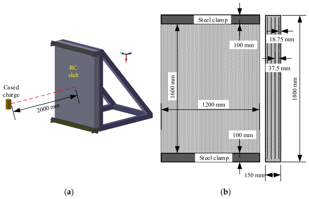
To verify the validity and accuracy of the numerical model, the experiment reported in ref. [6] was simulated, and the simulation results were compared to the experimental data. As illustrated in Figure 2a of the reference, the RC plate used in the blast test measured 1800 mm × 1200 mm × 150 mm. The C30 concrete had an average cube compressive strength of 31.12 MPa. The properties of the reinforcing steel included an average yield strength of 430 MPa, an ultimate strength of 669 MPa, and an elastic modulus of 210 GPa. The reinforcement grid consisted of longitudinal rebars (1750 mm in length) and transverse rebars (1120 mm in length) with 70 mm × 70 mm spacing. Four layers of steel mesh were arranged through the plate thickness, with an interlayer spacing of 37.5 mm and a concrete cover thickness of 18.75 mm. The RC plate was mounted within a square steel tube frame using bolts and steel restraining bars. The frame, which was constructed from 100 mm × 100 mm square steel tubes, matched the dimensions of the plate. After the restraints were installed, the exposed surface area measured 1600 mm × 1200 mm, as illustrated in Figure 2b.
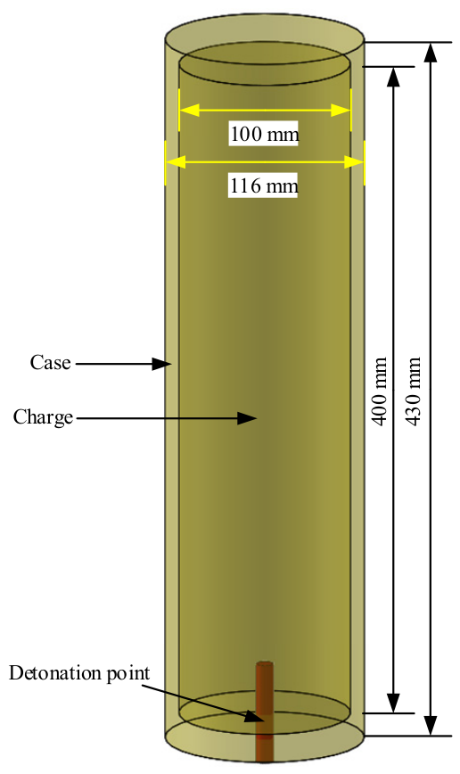
As shown in Figure 3, the cased charge assembly consisted of three components: an outer casing, an explosive filler, and end caps. Both the metallic casing and the end caps were fabricated from No. 45 steel, with a quasi-static yield strength of 320.5 MPa and an ultimate tensile strength of 488.6 MPa. The casing had a length of 430 mm, an inner diameter of 100 mm, and a wall thickness of 8 mm. Each end cap measured 100 mm in diameter and 15 mm in thickness, and was secured to the casing barrel by four high-strength bolts. The casing contained a cylindrical TNT charge 400 mm in length. This assembly was positioned 700 mm above the ground on a wooden frame, with a standoff distance of 2000 mm between the explosive centroid and the RC plate.
A validated numerical model replicating the test setup in ref. [6] is presented in Figure 4. The cased charge, surrounding air, and concrete were discretized using SOLID164 elements, while steel reinforcement was modeled with BEAM161 elements. Given the extremely short duration of the detonation phase relative to the structural response times, perfect bonding at the concrete–reinforcement interfaces was simulated through shared nodes. To mitigate the effects of boundary reflections on computational accuracy, an extended air domain measuring 3000 mm × 1600 mm × 2300 mm was established. Computational efficiency was enhanced through localized mesh refinement in the RC plate: a central region 600 mm in width was meshed with 5 mm elements, while the peripheral regions were meshed with 10 mm elements. Reinforcement elements maintained dimensional consistency with the adjacent concrete elements. The air domain was uniformly meshed with 20 mm elements, with all boundaries configured as non-reflective surfaces by the keyword BOUNDARY_NON_REFLECTING. The support of the RC plate by the square steel tube frame was simulated by constraining the displacement of the nodes in all directions within 100 mm around the RC plate. The keyword INITIAL_VOLUME_FRACTION_GEOMETRY was used to place the explosive within the air domain; the keyword SET_PART_LIST was used to group the air and explosive, and the rebar and concrete, as PART sets; and the keywords ALE_MULTI-MATERIAL_GROUP and CONSTRAINED_LAGRANGE_IN_SOLID were used to realize the fluid–solid coupling. The mass of the casing was 10.5 kg and the mass of the charge was 5.12 kg, consistent with the test.
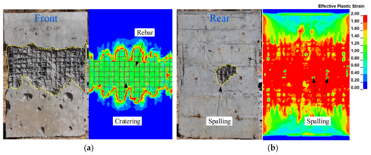
The rationality and computational accuracy of the numerical model were validated via comparison to the cratering mode and dimensions, as well as the back-face displacement of the RC plate between the blast test and the numerical simulations. A high-speed camera was used during the tests to record the dynamic response of the RC plate, and the cratering area was quantified using image processing techniques. Figure 5 compares the experimental and numerical simulation results of damage in a 150 mm thick C30 RC plate subjected to a blast at a standoff distance of 2 m. Quantitative analysis revealed a diamond-shaped breach area of 6.8 × 105 mm2 on the blast-exposed surface in the experiment. Using ImageJ (1.8.0) software, the numerically simulated damage area on the front face of the RC plate was measured as 6.5 × 105 mm2, representing a 4.4% difference compared to the experimental result.
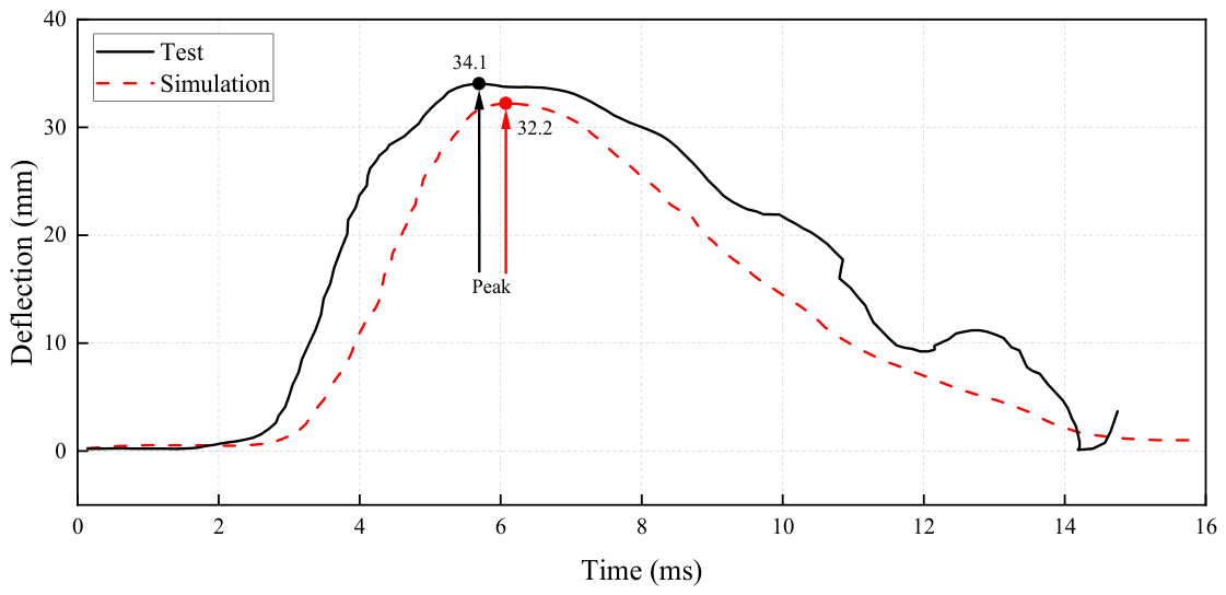
Figure 6 compares the displacement–time history curve at the center of the RC plate. The maximum displacement measured at the center of the RC plate in the experiment was approximately 34 mm, while the value obtained from the numerical simulation was approximately 32.2 mm. In addition, the duration of displacement in the numerical simulation was slightly shorter than that observed in the experiment. This phenomenon resulted from differences in boundary conditions between the experiment and the numerical simulation, as well as from the inherent non-uniformity and defects of the RC plate in the experiment. The specific reasons were as follows: (1) influence of boundary conditions: the numerical simulation employed idealized boundary conditions, whereas the experimental setup involved imperfect boundary constraints; (2) influence of the inherent non-uniformity and defects of the RC plate in the experimental setup.
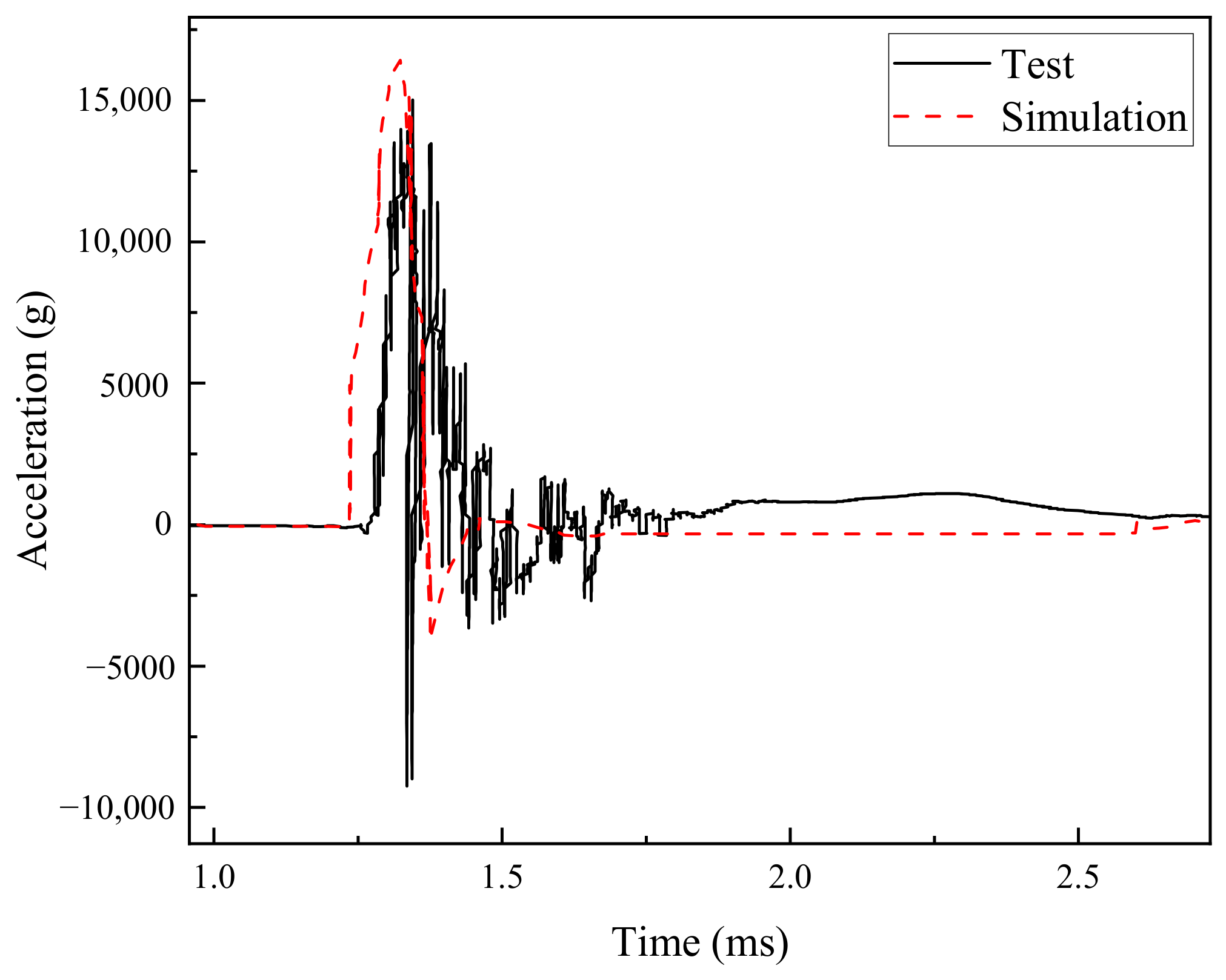
Figure 7 presents a comparison of the acceleration–time history at the mid-span on the rear face of the RC slab obtained from the numerical simulation and the experimental test [6]. A good agreement was observed in terms of the overall response trend, peak magnitude, and main vibration stages. The peak acceleration and its evolution, as well as the subsequent attenuation characteristics, were reasonably captured by the numerical model.
It was also observed that the simulated response was initiated slightly earlier than that measured in the experiment, and a marginally higher peak value was predicted. These discrepancies were mainly attributed to the inherent uncertainties associated with the experimental conditions, whereas the numerical model was established under relatively idealized assumptions. Despite these minor differences, satisfactory agreement was achieved overall, indicating that the proposed numerical model was capable of reproducing the dynamic response of the structure with reasonable accuracy. With the inclusion of the acceleration response comparison, the validation of the numerical model was further strengthened, thereby providing a more reliable basis for the subsequent parametric investigation of ECC protective layers.

3. Performance of the ECC Layer on the Response and Damage of the RC Plate

Under cased charge detonation, the explosion generated not only a high-intensity blast but also a large number of high-velocity fragments. The combined loading of the blast and fragments imposed severe and complex damage on structural materials. The blast, characterized by its extremely high propagation speed and concentrated energy, induced significant surface deformation or even spalling upon impact. Concurrently, the fragments, carrying substantial kinetic energy, penetrated the material surface or impacted it violently, resulting in localized damage, deep penetration, and crack propagation. This combined loading scenario presented a much greater threat to structural components compared to single loading conditions, as the structure had to simultaneously resist the impulsive pressure of blast and the localized, high-energy damage caused by the fragments’ impact. The synergistic effect of these two loading mechanisms led to a more complex failure process and placed higher demands on the resistance and energy absorption capacity of the material.
In this context, conventional protective measures proved insufficient to counteract the combined destructive effects of blast and high-velocity fragments. As a result, the incorporation of high-performance material ECC as protective layers garnered significant attention. ECC was capable of effectively absorbing the kinetic energy of both blast and fragments, thereby attenuating stress transmission to the underlying plate and mitigating structural damage. Owing to its superior crack-bridging capability and high ductility, ECC dissipated blast energy primarily through the formation of multiple cracks and fiber-bridging mechanisms. These deformation and damage control characteristics significantly enhanced the blast resistance of protective structures under extreme dynamic loading conditions.
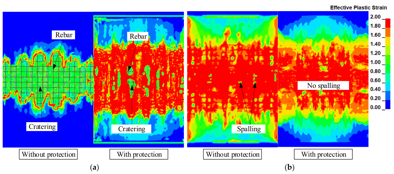
Figure 8 shows the plastic strain in the damage response of the RC plate, both with and without ECC protection. The RC plate without ECC exhibited pronounced and continuous erosion damage on the front face under the combined loading of the blast and fragments. The concrete cover underwent extensive spalling, with an erosion depth of approximately 20 mm, which was close to the full thickness of the cover. The reinforcing bars were largely exposed and showed slight bending. On the rear face, a small spalled region was observed due to tensile wave reflection, with a depth comparable to the cover thickness and accompanied by local bar exposure.
In contrast, the RC plate protected by the ECC exhibited significantly mitigated erosion, with only localized shallow surface damage, and the erosion depth remained within 10–20 mm. The eroded area on the front face was reduced by more than 60% compared to the unprotected RC plate. The reinforcing bars remained intact without displacement or bond failure, and no noticeable damage was observed on the rear face.
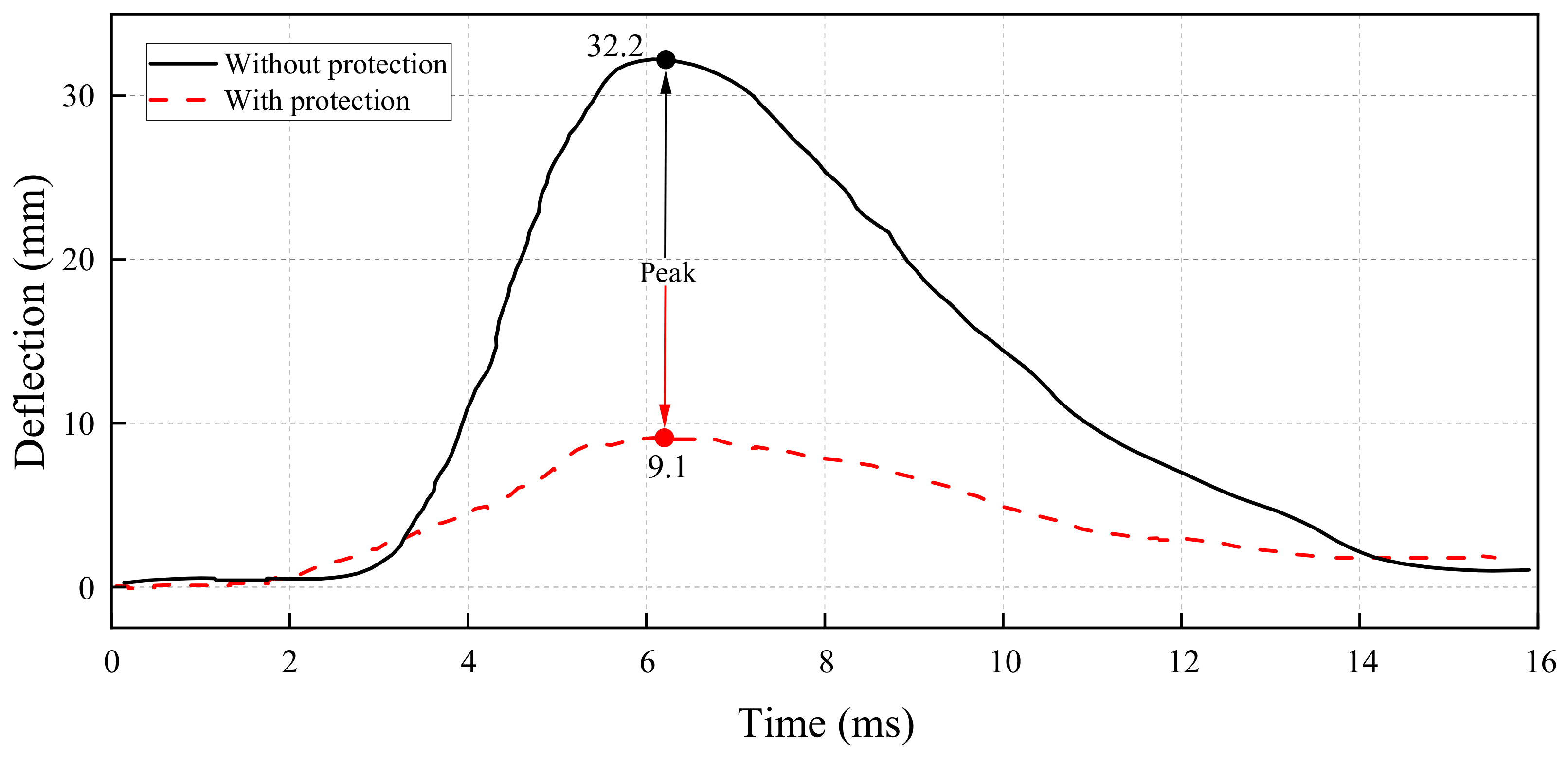
Figure 9 shows the time history curve of the central displacement on the rear surface of the RC plate with and without ECC protection. In the absence of ECC protection, the maximum central displacement reached approximately 32.2 mm. In contrast, with ECC protection, the corresponding displacement was significantly reduced to about 9.1 mm, representing a 71% decrease.
The protective mechanism of the ECC-reinforced RC plate lay in its ability to resist the combined loading of blast pressure and high-velocity fragments through a multiscale synergistic response. First, the high-density polyethylene (PE) fibers embedded in the ECC dissipated energy through fiber pull-out and slip under dynamic loading, thereby effectively suppressing macrocrack propagation. Second, the strain-hardening behavior of ECC allowed the material to undergo distributed cracking before failure, thereby redistributing localized stresses and preventing brittle spalling. Moreover, the strong interfacial bond between ECC and the reinforcing steel inhibited blast-induced debonding, ensuring effective composite action between the protective layer and the load-bearing RC plate. This hybrid energy dissipation mechanism, which combines ductility and strength, confined the erosion depth to less than 50% of the ECC layer thickness, significantly delaying reinforcement exposure and reducing the risk of corrosion, thereby providing enhanced protection for the underlying structural components.

4. Discussions

This chapter investigated the damage evolution mechanisms of an ECC-protected RC plate under multi-parameter coupling through numerical simulations, focusing on the regulation of flexural performance. A refined finite element model was developed, with ECC layer thicknesses of 10 mm, 20 mm, 30 mm, and 40 mm; compressive strengths of 30 MPa, 50 MPa, and 70 MPa; and single-sided and double-sided protection configurations selected as key variables. The quantitative influences of these parameters on the damage area of the RC plate, the central displacement response, and the energy absorption efficiency at the ECC-RC plate interface were systematically analyzed. Parametric simulations were used to elucidate the synergistic effects of ECC thickness and strength on the load transfer path, and to reveal the differences in energy distribution associated with single-sided and double-sided protection schemes.

4.1. Thickness of ECC Layer

To systematically evaluate the effect of the thickness of the ECC protective layer on the blast resistance performance of the RC plate, a series of comparative scenarios were designed based on the coupled effects of fragment penetration and blast loading. For the ECC protected groups (T-10 to T-40), ECC layers with thicknesses of 10 mm, 20 mm, 30 mm, and 40 mm were applied to the front (blast-facing) surface of the RC plate, respectively. The blast loading conditions were kept consistent with those used in the experimental setup described earlier. By employing a gradient thickness design, the nonlinear relationship between protective layer thickness and both the damage pattern and energy absorption efficiency was explored. In all scenarios, the structural boundary conditions were modeled to reflect actual engineering constraints, and the propagation of the blast and fragment penetration was simulated using a multi-material Arbitrary Lagrange–Eulerian (ALE) coupling algorithm. Key indicators such as the concrete spalling area, the central displacement of the rear surface of the RC plate, and energy absorption were extracted to systematically analyze the influence of ECC thickness on the dynamic response.
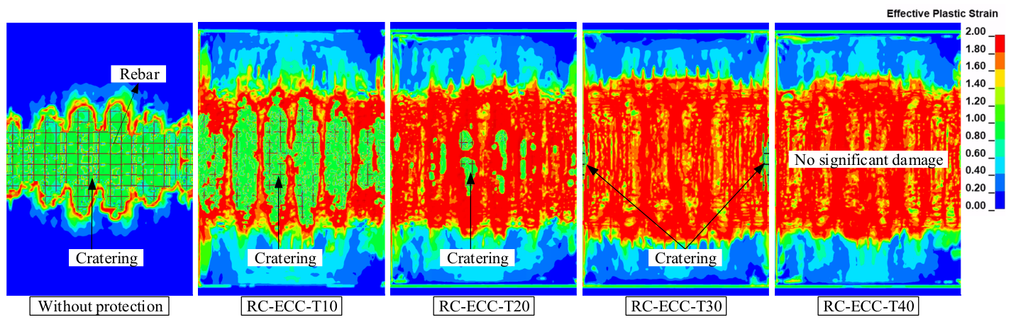
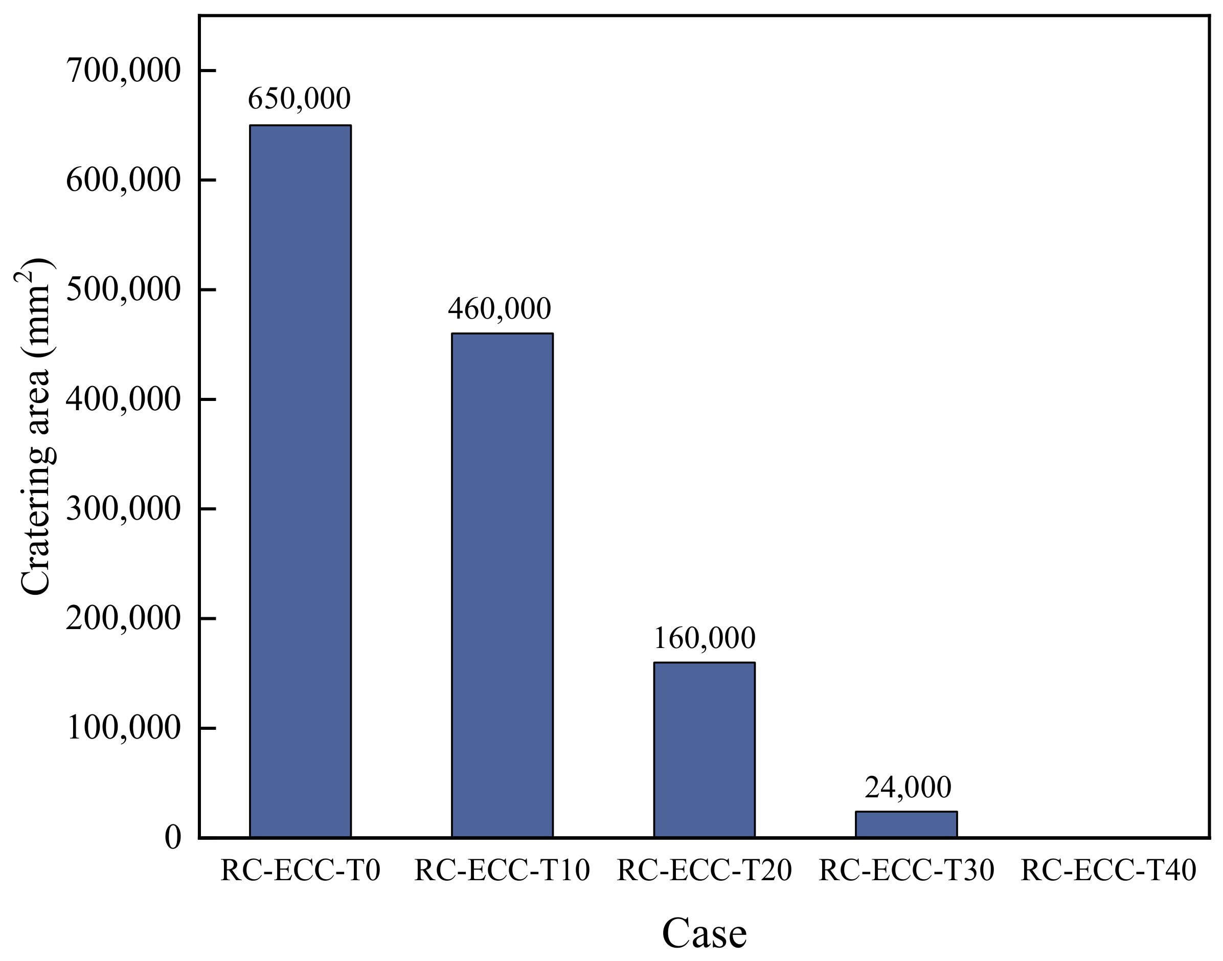
The damage on the front surface of the RC plate under different ECC protective layer thicknesses is shown in Figure 10. To assess the effectiveness of ECC in mitigating damage to the RC plate, Figure 11 shows the variation in the cratering area under combined loading of the blast and fragments for the RC plate without protection and with ECC layers of varying thicknesses. The results indicated that the ECC layer thickness played a significant role in controlling cratering damage on the front surface of the RC plate. As the thickness of the ECC layer increased, the cratering area consistently decreased, and the severity of damage was notably reduced. When the ECC layer reached a thickness of 30 mm, the material effectively absorbed and dissipated most of the blast’s and fragments’ impact energy, significantly reducing the dynamic loads transmitted to the RC plate and substantially suppressing surface spalling. When the ECC thickness was further increased to 40 mm, no apparent spalling damage was observed on the RC surface, indicating that the protective performance had stabilized.
The suppression of rear-face spalling damage in the RC plate by the ECC protective layer could be attributed to several key mechanisms. Under blast loading, the ECC exhibited typical strain-hardening behavior accompanied by the propagation of multiple cracks, while the internal fiber-bridging effect facilitated effective energy dissipation and promoted the transformation of the incident compressive stress wave into a distributed damage pattern during propagation, thereby reducing its effective intensity through the thickness. In addition, as the ECC layer thickness increased, the propagation path of the stress wave within the protective layer was extended, resulting in a pronounced time-delay effect before the compressive wave reached the RC plate and consequently mitigating instantaneous stress concentration. Furthermore, the introduction of the ECC layer enhanced the overall flexural stiffness and wave impedance characteristics of the composite structural system, thereby reducing the tensile stress amplitude generated by the reflection of the compressive wave at the rear free surface, which ultimately suppressed rear-face spalling in the RC plate.
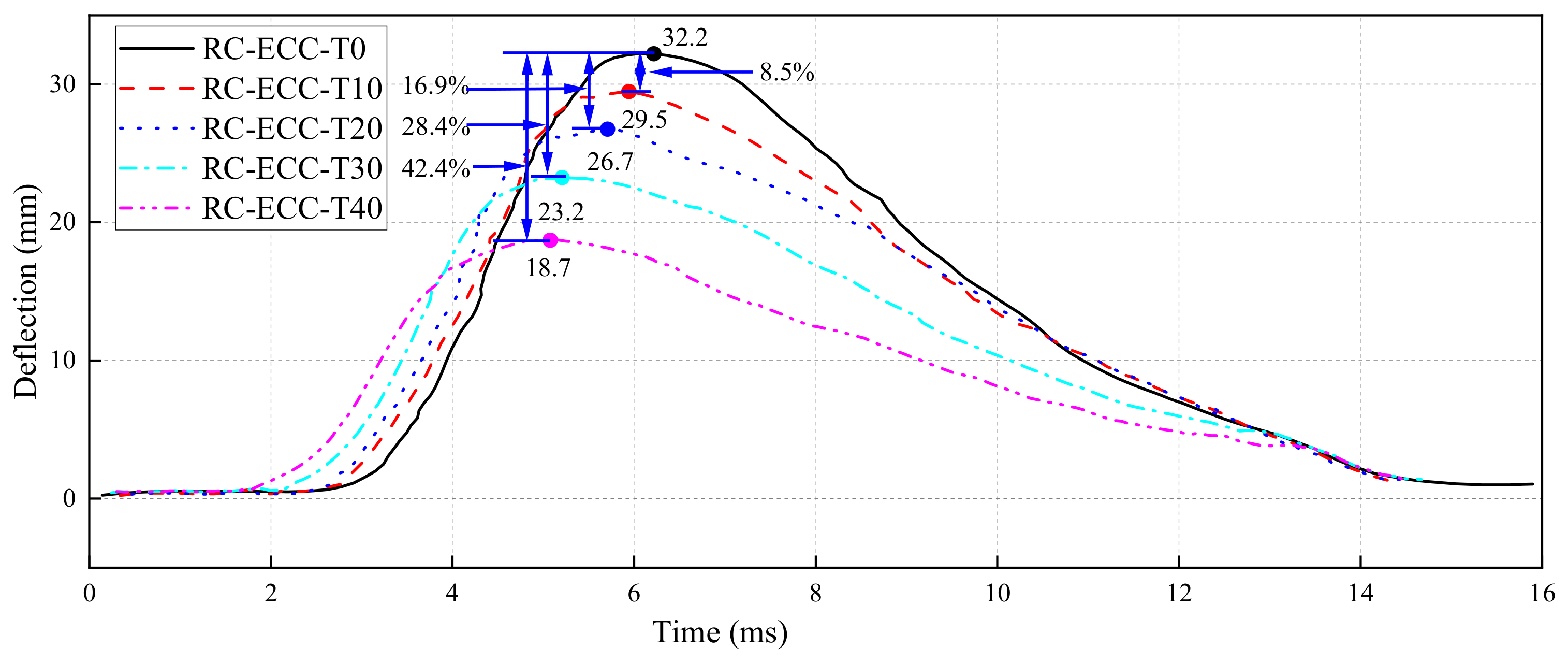
Figure 12 shows the time history curve of the central displacement for the RC plate without protection and with ECC layers of varying thicknesses. The unprotected RC plate exhibited a maximum displacement of 32.2 mm. As the ECC thickness increased, the peak displacement decreased sequentially to 29.5 mm, 26.7 mm, 23.2 mm, and 18.7 mm, corresponding to 91.4%, 83.0%, 71.6%, and 57.6% of that of the unprotected case, respectively. In addition, the time to peak displacement shifted earlier from 6.1 ms to 4.9 ms with increasing ECC thickness, indicating that the stiffer RC-ECC plate responded more rapidly to blast loading.
From a mechanical perspective, the inclusion of an ECC layer markedly increased the global stiffness and flexural capacity of the composite system, thereby enhancing its resistance to deformation under transient impact loading. During the initial response phase, the characteristic multiple-cracking and fiber-bridging mechanisms of ECC effectively absorbed and dissipated the incident energy, impeding its rapid transmission into the RC plate and thus suppressing large deformations. Moreover, the ECC layer introduced an impedance mismatch within the composite plate, promoting partial stress wave reflection or absorption at the interface, which accelerated energy redistribution and consequently led to an earlier displacement peak. An evaluation of the reduction in central displacement per 10 mm increase in ECC thickness yielded decreases of 2.7 mm, 2.7 mm, 3.7 mm, and 4.5 mm, respectively, demonstrating a progressively increasing suppression efficiency with increasing thickness. This trend indicated that beyond an ECC thickness of 30 mm, the marginal gains in energy dissipation and deformation control were amplified, thereby conferring superior protective performance.

4.2. Effect of RC Slab Parameters Under ECC Protection

To further evaluate the sensitivity of the structural response of RC slabs to their intrinsic parameters under combined blast and fragment loading, a parametric study was conducted while maintaining a constant ECC protection thickness. Specifically, the slab thickness was varied, and the damage responses of RC slabs with thicknesses of 10 cm, 15 cm, and 20 cm under 10 mm ECC protection were investigated. In addition, taking the 15 cm thick RC slab as the reference case, the reinforcement ratio was varied as 0.5%, 1.0%, and 2.0%, and the corresponding damage responses under 10 mm ECC protection were analyzed.

4.2.1. Effect of RC Slab Thickness

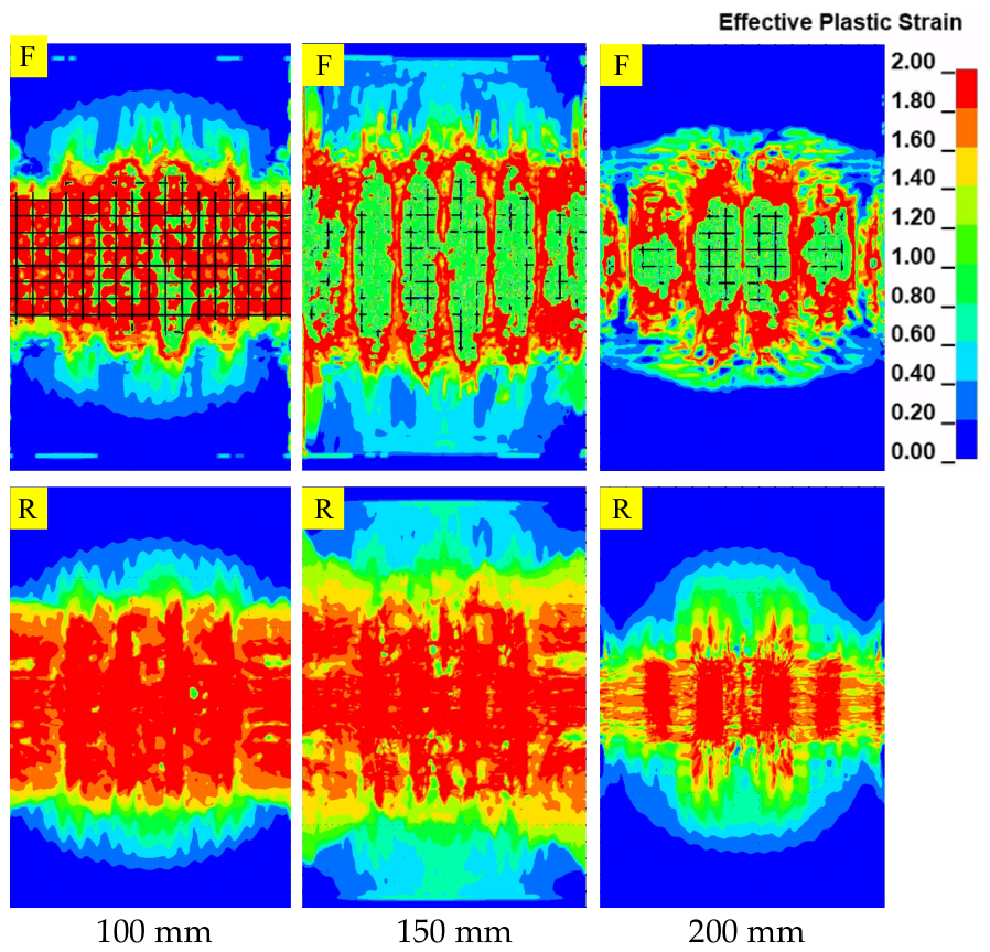
Figure 13 illustrates the damage responses of RC slabs with different thicknesses under combined blast and fragment loading, with a 10 mm ECC protection layer applied. It was observed that, as the slab thickness increased from 100 mm to 200 mm, the highly damaged regions on the front surface gradually shrank, and their spatial extent was significantly reduced. This indicated that the resistance of the structure to fragment-induced local erosion was progressively enhanced. This phenomenon was mainly attributed to two factors. On the one hand, the increase in slab thickness led to an enhancement in the overall structural stiffness, thereby reducing local stress concentration effects. On the other hand, the increase in the thickness of the concrete cover improved the buffering and energy dissipation capacity against fragment impact, which reduced the direct exposure of the reinforcement.
From the perspective of damage distribution, for the thinner slab (100 mm), regions with high effective plastic strain exhibited a pronounced tendency to propagate through the thickness. As the slab thickness increased to 150 mm and 200 mm, the damage became more concentrated near the blast-facing surface, while the damage levels in the interior and rear regions were significantly reduced, indicating a more pronounced attenuation of the impact effect during wave propagation.
Furthermore, under the protection of the ECC layer, no obvious concrete spalling was observed at the rear face of the RC slabs in all cases, and the rear regions remained at relatively low damage levels. This suggested that the ECC layer effectively absorbed and dissipated the impact energy, while also reducing the propagation and reflection intensity of stress waves within the RC slab, thereby significantly suppressing rear-face tensile failure. Overall, the combined effect of ECC protection and slab thickness was found to effectively enhance the impact resistance of the structure, in which the ECC layer primarily suppressed the occurrence of damage, while the slab thickness further influenced the extent and distribution characteristics of the damage.

4.2.2. Effect of RC Slab Reinforcement Ratio

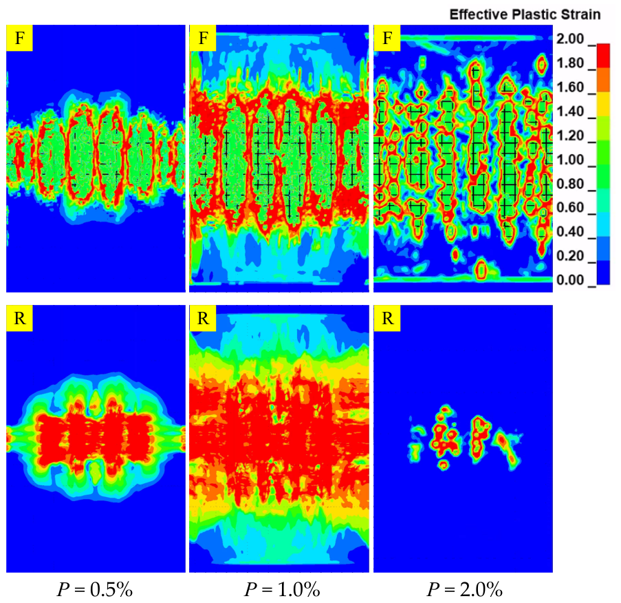
Figure 14 illustrates the damage responses of RC slabs with different reinforcement ratios (0.5%, 1.0%, and 2.0%) under combined blast and fragment loading with a 10 mm ECC protection layer, characterized by the effective plastic strain, F denotes the front surface, and R denotes the rear surface. It was observed that the distribution pattern of highly damaged regions varied significantly with the increase in the reinforcement ratio. For the case with a reinforcement ratio of 0.5%, the regions with high effective plastic strain were mainly localized within the impact zone and exhibited a relatively discrete distribution. As the reinforcement ratio increased to 1.0%, the damaged regions became more continuous within the slab. When the reinforcement ratio further increased to 2.0%, the damage pattern was refined and exhibited a distinct band-like distribution aligned with the reinforcement layout, indicating the pronounced influence of reinforcement on the local stress field.
From a mechanistic perspective, the increase in reinforcement ratio was associated with an enhancement in the overall load-carrying capacity and confinement effect of the slab, leading to a more distributed dissipation of impact energy. Meanwhile, the reduction in bar spacing at higher reinforcement ratios altered the crack propagation paths and strengthened the local confinement of concrete, resulting in a more dispersed and multi-point damage pattern. It should be noted that previous studies suggested that a higher reinforcement ratio may increase the likelihood of concrete cover spalling due to reduced bar spacing. However, under the ECC protection considered in this study, no obvious spalling was observed at the rear face of the RC slabs, and the overall damage response was dominated by the energy absorption and dissipation capacity of the ECC layer.
Furthermore, a comparison of the rear-face responses under different reinforcement ratios indicated that the overall damage level tended to decrease with increasing reinforcement ratio, suggesting that the presence of reinforcement contributed to the suppression of tensile damage induced by stress wave propagation. Overall, while the reinforcement ratio significantly affected the distribution characteristics of damage, its influence on rear-face spalling was substantially mitigated by the presence of the ECC protection layer.

4.3. Equivalent RC Thicknesses

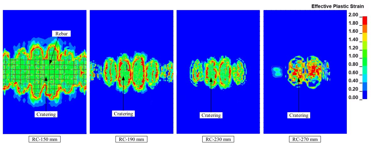
To obtain the equivalent RC slab thicknesses corresponding to different ECC protection thicknesses, additional numerical simulations were conducted by increasing the thickness of the concrete cover on both sides of the RC slab by 20 mm, 40 mm, and 60 mm, resulting in total slab thicknesses of 190 mm, 230 mm, and 270 mm, respectively. The comparison of damage responses between RC slabs protected with ECC layers of different thicknesses and unprotected RC slabs with increased thicknesses is presented in Figure 15. The results indicated that, under ECC protection, a significant portion of the fragment kinetic energy was dissipated by the ECC layer, and direct impact on the underlying concrete was effectively mitigated. As a result, the damage of the rear RC slab was progressively reduced with increasing ECC thickness, and no obvious surface damage was observed at higher protection levels. In contrast, the unprotected RC slabs were continuously subjected to direct fragment impact. Although the exposed reinforcement area on the front surface decreased with increasing concrete cover thickness, localized erosion of the surface concrete still persisted, and the overall damage pattern remained essentially unchanged.
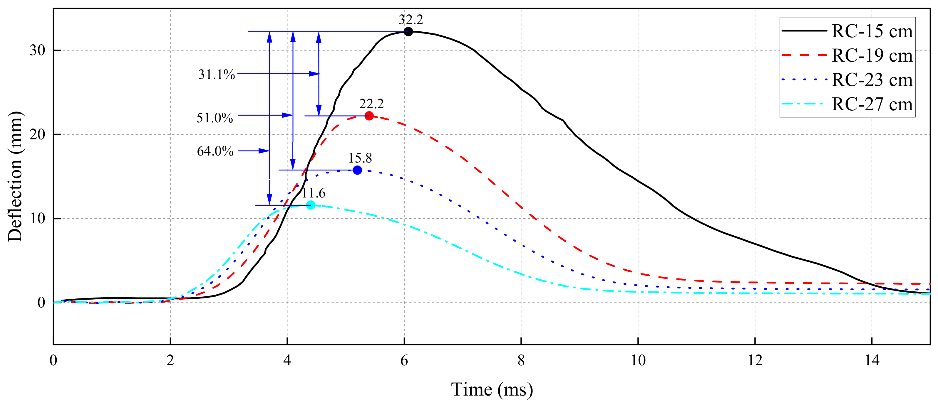
Figure 16 presents the comparison of mid-span displacement–time history responses at the rear face between ECC-protected slabs and the corresponding unprotected RC slabs. The results showed that increasing the concrete cover thickness effectively reduced the mid-span deflection. When the cover thickness was increased by 60 mm, the maximum mid-span displacement was reduced to 11.6 mm, corresponding to a reduction of approximately 64% compared to the reference case.
Under combined blast and fragment loading conditions, for unprotected RC slabs, the increase in structural thickness was found to be insufficient to eliminate the local erosion effect induced by fragments, and spalling of the front surface concrete was still observed. In contrast, for RC slabs protected with ECC layers, the spalling area was significantly reduced with increasing ECC thickness, and was even completely suppressed under certain conditions. Since the damage evolution mechanisms were significantly different between the two cases, and the spalling area was substantially reduced or completely suppressed under ECC protection, the use of the spalling area as an equivalent comparison index was considered to be inconsistent and inappropriate.
Therefore, the mid-span deflection at the rear face was adopted as a unified evaluation index to establish equivalence between the two conditions. For unprotected RC slabs with different thicknesses, data fitting was performed by taking the slab thickness as the independent variable and the rear mid-span displacement as the dependent variable. Accordingly, a relationship between displacement and thickness was established. Then, the mid-span displacements of RC slabs with different ECC protection thicknesses were substituted into the fitted relationship, and the corresponding equivalent RC slab thicknesses were then obtained.

4.4. The Compressive Strength of ECC

Numerical simulations were conducted to systematically examine the influence of ECC compressive strength grades (C30, C50, and C70) on the damage behavior of the RC plate. A parameterized finite-element model was developed under a single-sided protection scheme with a fixed ECC thickness of 20 mm. The ECC material was modeled using the *MAT_CONCRETE_DAMAGE_REL3 (K&C) model, in which the constitutive parameters were determined following the modified formulation proposed by Xu et al. [57]. In this approach, the parameters defining the strength surfaces were expressed as functions of the compressive strength f c allowing a consistent representation of ECC materials with different strength grades within a unified modeling framework. Based on this formulation, comparative analyses were performed to evaluate the damage area, energy-absorption characteristics, and peak mid-span displacement of the RC plate at the three strength levels.
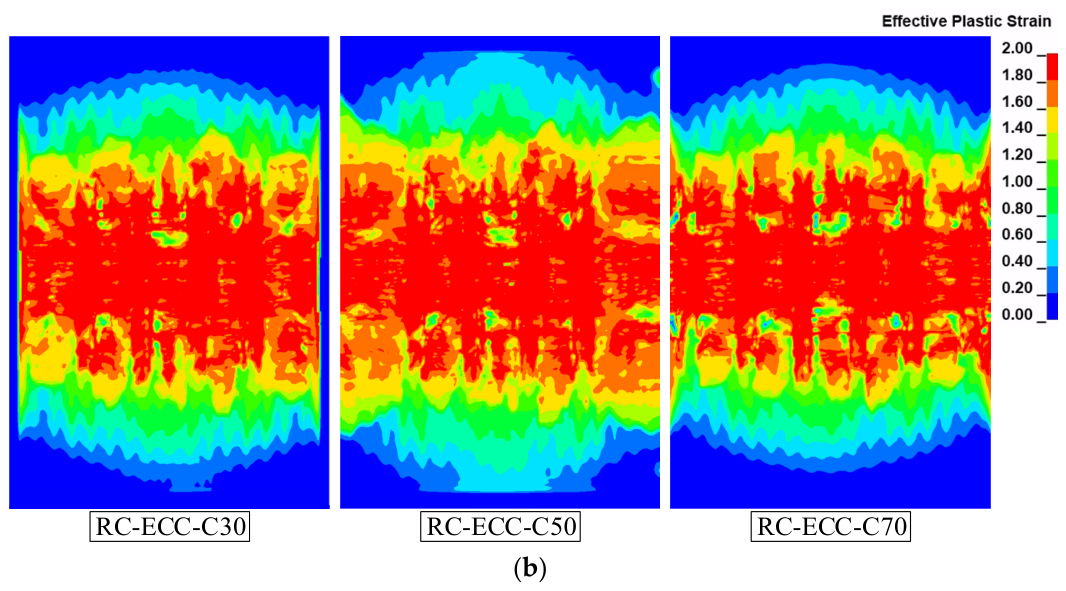
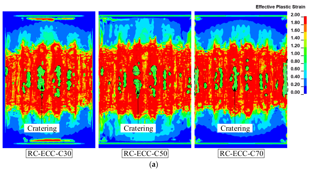
Figure 17 shows the damage response of the RC plate under ECC protection with different strength grades. Numerical simulations revealed that, despite the variation in ECC strength, all plates exhibited comparable degrees of spalling on the front surface, with minimal differences in the overall damage between the front and rear faces. This behavior stemmed from the intrinsic properties of ECC: its exceptional ductility and multiple-cracking capacity promoted the formation of numerous fine cracks under tensile loading rather than a single wide crack, thereby efficiently dissipating blast energy. The high ductility and tensile strain capacity were crucial for blast protection, as the ECC layer, through multi-crack propagation and material deformation mechanisms, delayed crack penetration into the RC plate, reduced local stress concentrations, and enhanced the overall damage resistance of the composite structure.
However, previous studies [58,59] indicated that ECC with different compressive strength grades exhibited limited variation in ductility and energy-dissipation capacity, suggesting that tensile deformation performance was not directly governed by compressive strength. Consequently, increasing the compressive strength of ECC resulted in only marginal improvement in the protective performance of the RC plate, leading to similar damage patterns across different strength grades. Overall, in blast-loading protection design, prioritizing the ductility and fracture toughness of ECC rather than merely increasing its compressive strength was more effective.
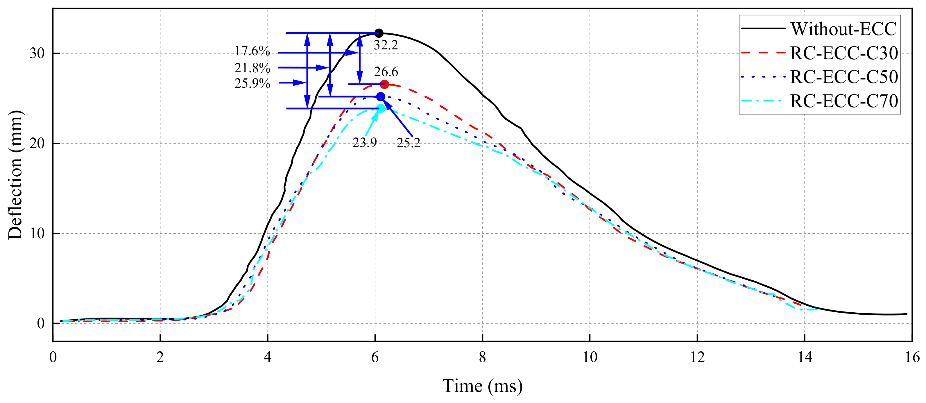
Figure 18 shows the rear-face mid-span displacement of the RC plate under no protection and under ECC layers with strength grades of C30, C50, and C70. The unprotected RC plate exhibited a peak displacement of 32.2 mm. With the addition of C30, C50, and C70 ECC layers, the peak displacements decreased to 26.6 mm, 25.2 mm, and 23.9 mm, respectively. Although a decreasing trend in displacement was observed with increasing ECC strength, the extent of reduction was relatively limited, and the improvement tended to diminish at higher strength grades, indicating that the influence of compressive strength on deformation control was not significant.
From a mechanical perspective, high-strength ECC indeed provided greater compressive and shear stiffness, thereby slowing crack propagation and enhancing stress wave reflection to attenuate blast transmission into the RC plate. However, the limited improvement in displacement control arose because, at a fixed thickness, the ECC layer primarily absorbed the initial impulse; as the strength increased, its ductility and energy-dissipation capacity might decrease, making further stiffness gains progressively less effective in mitigating displacement. In summary, while increasing the compressive strength of ECC could enhance the RC plate’s blast resistance to some extent, its ability to suppress mid-span displacement was relatively limited. In optimized designs, a balance among ECC strength, ductility, and thickness should be sought to achieve an optimal compromise between stiffness and energy-dissipation capacity for superior protective performance.

4.5. Single/Double-Sided ECC Protection

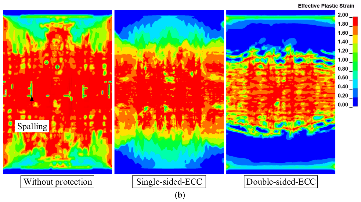
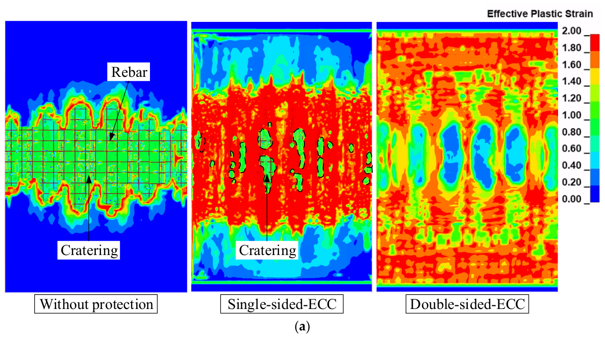
Figure 19 shows the damage response of the RC plate under unprotected conditions, single-sided ECC protection, and double-sided ECC protection. Under unprotected conditions, the RC plate exhibited pronounced asymmetric damage: the blast-facing concrete underwent extensive delamination and spalling up to 18–22% of the thickness, with significant surface crack propagation due to direct blast loading, while the rear face was governed by primarily flexural tensile action, resulting in fewer cracks concentrated radially. In contrast, single-sided ECC protection substantially improved the damage profile: the ECC layer’s multiple-cracking and fiber-bridging mechanisms absorbed most of the blast energy, confining spalling within the ECC itself and reducing concrete erosion by 76%, with only localized, minor surface peeling (<5% depth) and no evident structural failure. Double-sided ECC protection further optimized damage distribution and virtually eliminated RC plate cracking: The peak plastic strains on both faces were markedly reduced, and only slight, uniformly distributed damage was observed without discernible cracks or spalling, which demonstrated that bilateral ECC layers effectively dispersed blast energy and dramatically enhanced the RC plate’s overall blast resistance.
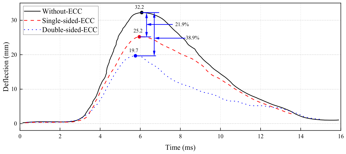
The comparative results indicated that the protective efficacy of ECC layers under different configurations was evident. Single-sided ECC protection effectively mitigated blast face damage and reduced rear face erosion, whereas double-sided ECC protection provided the most effective defense, nearly completely suppressing crack initiation. These findings provided a theoretical basis for the design of efficient structural protection systems. In particular, under high-intensity blast loading, double-sided ECC protection exhibited superior performance, markedly enhancing the RC plate’s blast resistance and overall structural stability.
Figure 20 shows the time history curve of the back-face mid-span displacement for the RC plate under unprotected conditions, single-sided ECC protection, and double-sided ECC protection. The unprotected RC plate exhibited a maximum mid-span displacement of 32.3 mm; with single-sided ECC protection, this value decreased to 25.2 mm; under double-sided ECC protection, the displacement was further reduced to 19.7 mm, corresponding to reductions of 21.9% and 38.9%, respectively, relative to the unprotected case. These results demonstrated that ECC layers markedly improved the RC plate’s blast-induced displacement response, with the double-sided configuration providing the most effective deformation control.
In summary, the configuration of the ECC protective layer significantly influenced the effectiveness of the dynamic response control of the RC plate. Double-sided ECC protection not only effectively reduced the peak displacement but also demonstrated superior structural integrity and energy dissipation capacity, making it particularly suitable for engineering structures with higher blast resistance requirements.

5. Conclusions

In this study, to enhance the resistance of RC plates under the combined loading of blast and fragments, a method of installing ECC protective layers onto RC plates was proposed, and its performance was evaluated. It was found that this approach could effectively reduce the response and damage of the RC plates. In addition, the influence of major governing factors on the protective effectiveness was investigated and underlying mechanisms were explained, including the ECC layer thickness, compressive strength, reinforcement ratio, and installation configuration. Moreover, an equivalent thickness design approach for ECC layers was proposed. The main conclusions are summarized as follows:
  • ECC thickness was the key factor governing the enhancement of resistance against blast and fragments. As the ECC layer thickness increased from 10 mm to 40 mm, the concrete cratering area on the front surface was reduced from approximately 650,000 mm2 (unprotected case) to 460,000 mm2, 160,000 mm2, 24,000 mm2, and finally to nearly zero, corresponding to reductions of about 29%, 75%, 96%, and 100%, respectively. Meanwhile, the central displacement of the RC plate decreased from 32.2 mm to 29.5 mm, 26.7 mm, 23.2 mm, and 18.7 mm, indicating a maximum reduction of approximately 42%. These results indicated that increasing ECC thickness effectively suppressed local damage and significantly improved the global deformation resistance of the structural member.
  • Increasing the protective layer thickness reduced front-surface spalling and reinforcing bar exposure. For unprotected RC slabs, increasing the concrete cover thickness reduced rear-face displacement but could not eliminate fragment-induced local erosion or change the overall damage mode. When the cover thickness increased by 60 mm, the peak mid-span central displacement decreased by about 64%. In contrast, increasing ECC thickness effectively dissipated fragment kinetic energy, significantly reduced slab damage, and even suppressed visible surface damage. Reducing the reinforcement ratio to 0.5% had little effect on slab damage, whereas increasing it to 2.0% aggravated front-surface spalling. Therefore, rear-face central deflection was adopted as the evaluation index to determine the equivalent RC thickness of ECC protection.
  • The compressive strength of ECC was found to have a limited influence on the protective effectiveness of the system. Compared to the unprotected RC plate (32.2 mm), the peak central displacement was reduced to 26.6 mm, 25.2 mm, and 23.9 mm for C30, C50, and C70 ECC, respectively, corresponding to reductions of approximately 17%, 22%, and 26%. Although a gradual decrease in displacement was observed with increasing compressive strength, the overall improvement remained relatively limited, and similar damage patterns were obtained across different strength grades. This indicated that increasing compressive strength alone did not substantially enhance the resistance of the RC plate under combined blast and fragment loading, whereas the intrinsic ductility and energy dissipation capacity of ECC played a more dominant role.
  • The protective configuration significantly affected the response characteristics of the RC plate. Compared to the unprotected case (32.2 mm), the central displacement was reduced to 25.2 mm under single-sided ECC protection and further decreased to 19.7 mm under double-sided protection, corresponding to reductions of approximately 22% and 39%, respectively. Single-sided ECC protection effectively mitigated cratering and erosion damage on the blast-facing surface, while double-sided protection further suppressed plastic strain development and crack propagation on both the front and rear surfaces, demonstrating a more pronounced enhancement in structural integrity.
In summary, the application of ECC layers in the blast-resistant strengthening of RC plates showed clear protective benefits. By setting a reasonable ECC layer thickness, compressive strength grade, reinforcement ratio, and installation configuration and by adopting the equivalent thickness design approach proposed in this study, the response and damage of RC structures under combined loading of blast and fragments could be effectively reduced. These findings provide a reference for the design and engineering application of ECC-based protective systems for RC structural members.

Author Contributions

Conceptualization, H.Z. and X.W.; methodology, H.Z. and X.W.; software, T.H.; validation, T.H. and X.W.; formal analysis, H.Z.; investigation, T.H., X.W. and H.Z.; resources, H.Z.; data curation, T.H.; writing—original draft preparation, T.H.; writing—review and editing, X.W. and H.Z.; visualization, T.H.; supervision, X.W.; project administration, H.Z.; funding acquisition, H.Z. All authors have read and agreed to the published version of the manuscript.

Funding

This research received no external funding.

Data Availability Statement

The data that support the findings of this study are available from the corresponding author, upon reasonable request.

Conflicts of Interest

The authors declare no conflicts of interest.

References

  1. Maazoun, A.; Atoui, O.; Ben Rhouma, M. Experimental investigation of CFRP-wrapped RC columns under contact explosions: Effects of single vs. dual-layer configurations. Buildings 2026, 16, 943. [Google Scholar] [CrossRef]
  2. Rathnayaka, P.T.; Son, J.S.; Kwak, J.W.; Yoo, S.J.; Lee, J.Y. Experimental and numerical investigations of blast resistance of fiber-reinforced concrete slabs. Buildings 2026, 16, 686. [Google Scholar] [CrossRef]
  3. Gao, C.; Jia, Y.S.; Yuan, S.J.; Wang, X.X. Damage evaluation of RC bridge columns subjected to close-in explosions considering failure modes. Buildings 2025, 15, 4199. [Google Scholar] [CrossRef]
  4. Lim, J.Y.; Goh, C.Y.M.; Kang, K.W.; Li, J.; Wu, C.Q. Structural response of steel-concrete composite panels to near field simultaneous blast and fragmentation loading. Int. J. Impact Eng. 2025, 195, 105142. [Google Scholar] [CrossRef]
  5. Wang, J.X.; Zhang, Z.Y.; Liu, K.; Yang, J.J.; Wang, Z.L. Study on damage characteristics of sandwich plate under the combined action of explosion shock wave and randomly distributed fragments. Ocean Eng. 2024, 309, 118575. [Google Scholar] [CrossRef]
  6. Zhang, S.; Wang, Z.Q.; Li, S.T.; Chen, Y.Q.; Chen, L.M.; Gao, Z.; Zhao, S.J. Experimental study of damage modes of RC and RCS walls under combined loading of fragments and shock waves. Int. J. Impact Eng. 2024, 194, 105065. [Google Scholar] [CrossRef]
  7. Liang, M.Z.; Zhou, M.; Qi, Z.Z.; Li, X.Y.; Lin, Y.L.; Lu, F.Y.; Li, Z.B. Failure mode and blast resistance of polyurea coated metallic cylinders under internal multi-field coupled loading. Thin-Walled Struct. 2023, 184, 110522. [Google Scholar] [CrossRef]
  8. Liu, J.; Wei, J.; Li, J.; Su, Y.; Wu, C.Q. A comprehensive review of ultra-high performance concrete (UHPC) behaviour under blast loads. Cem. Concr. Comp. 2024, 148, 105449. [Google Scholar] [CrossRef]
  9. Lin, L.; Xu, N.; Yang, D.; Li, G.Z.; Xiao, Y.M.; Yu, Y. A smart computational framework for predicting mechanical and sustainability indicators and optimizing mix proportions of recycled rubber aggregate concrete. Eng. Appl. Artif. Intell. 2026, 164, 113364. [Google Scholar] [CrossRef]
  10. Lin, L.; Xu, N.; Yang, D.; Xiao, Y.; Yu, Y. Effects of aged mortar on mechanical behavior of recycled aggregate Concrete: Experimental Tests, Microplane-Based mesoscale simulation and design Implications. Eng. Fail. Anal. 2026, 186, 110521. [Google Scholar] [CrossRef]
  11. Wang, W.Q.; Wang, Z.B.; Li, M.H.; Xiong, Z.L.; Chen, D.; Wu, C.Q. Close-range blast behavior of hybrid FRP-concrete-steel double-skin tubular member. Thin-Walled Struct. 2025, 211, 113022. [Google Scholar] [CrossRef]
  12. Wu, Q.S.; Wang, X.Y.; Ashour, A.; Sun, T.; Dong, S.F.; Han, B.G. Blast-resistance characteristics and design of steel wire reinforced ultra-high performance concrete slabs. Int. J. Impact Eng. 2024, 193, 105059. [Google Scholar] [CrossRef]
  13. Thai, D.K.; Tran, M.T.; Phan, Q.M.; Pham, T.H. Local damage of the RC tunnels under ballistic missile impact investigated by finite element simulations. Structures 2021, 31, 316–329. [Google Scholar] [CrossRef]
  14. Chen, Z.J.; Li, J.; Zong, Z.H.; Li, J.Q.; Li, M.H.; Wu, C.Q. Damage analysis of RC panels subjected to shock wave and bubble pulse in underwater explosion. Eng. Struct. 2025, 335, 120331. [Google Scholar] [CrossRef]
  15. Lyu, C.X.; Yan, Q.S. Field test and fragility analysis of RC box girder bridges subjected to contact explosion. Eng. Struct. 2025, 322, 119063. [Google Scholar] [CrossRef]
  16. Wang, W.; Wei, G.S.; Wang, X.; Yang, J.C. Structural damage assessment of RC slab strengthened with POZD coated steel plate under contact explosion. Structures 2023, 48, 31–39. [Google Scholar] [CrossRef]
  17. Gao, Z.; Chen, Y.Q.; Wang, Z.Q.; Li, S.T.; Wei, W.L.; Huang, C.L. Study on the failure effect of aramid reinforced concrete slab under localized blast loading. Structures 2024, 63, 106292. [Google Scholar] [CrossRef]
  18. Mu, M.; Liu, F.; Li, J.; He, F.; Liu, S.F.; Li, C.; Yang, Y. Influence of modified polyurea coating thickness on the blast resistance of RC slab. Structures 2024, 67, 107009. [Google Scholar] [CrossRef]
  19. Yu, S.Y.; Zhang, G.K.; Wang, Z.; Liu, J.; Deng, S.X.; Song, X.Z.; Wang, M.Y. Experimental and numerical study of corrugated steel-plain concrete composite structures under contact explosions. Thin-Walled Struct. 2024, 197, 111624. [Google Scholar] [CrossRef]
  20. Yao, S.J.; Zhang, D.; Chen, X.G.; Lu, F.Y.; Wang, W. Experimental and numerical study on the dynamic response of RC slabs under blast loading. Eng. Fail. Anal. 2016, 66, 120–129. [Google Scholar] [CrossRef]
  21. Wu, Y.Y.; Wang, J.H.; Liu, F.; Mu, C.M.; Xia, M.; Yang, S.K. A Research Investigation into the Impact of Reinforcement Distribution and Blast Distance on the Blast Resilience of Reinforced Concrete Slabs. Materials 2023, 16, 4068. [Google Scholar] [CrossRef]
  22. Tai, Y.S.; Chu, T.L.; Hu, H.T.; Wu, J.Y. Dynamic response of a reinforced concrete slab subjected to air blast load. Theor. Appl. Fract. Mech. 2011, 56, 140–147. [Google Scholar] [CrossRef]
  23. Park, D.; Lee, T.H.; Lee, Y.; Hong, J.W. Numerical study of RC slab failure mechanisms under varying blast loads. J. Build. Eng. 2026, 120, 115435. [Google Scholar] [CrossRef]
  24. Kumar, V.; Kartik, K.V.; Iqbal, M.A. Experimental and numerical investigation of reinforced concrete slabs under blast loading. Eng. Struct. 2020, 206, 110125. [Google Scholar] [CrossRef]
  25. Wu, C.; Nurwidayati, R.; Oehlers, D.J. Fragmentation from spallation of RC slabs due to airblast loads. Int. J. Impact Eng. 2009, 36, 1371–1376. [Google Scholar] [CrossRef]
  26. Chen, B.; Hou, L.; Yan, R.G.; Zhang, X.Y.; Meng, H.; Li, J.T. Flexural performance and flexural toughness evaluation method of high-strength engineered cementitious composites. Buildings 2025, 15, 4003. [Google Scholar] [CrossRef]
  27. Hamoda, A.; Ahmed, M.; Ghalla, M.; Fayed, S.; Abadel, A.A. Application of engineered cementitious composites reinforced with orthogonal welded steel mesh in enhancing axial performance of reinforced concrete walls: Experimental and numerical analysis. Buildings 2026, 16, 829. [Google Scholar] [CrossRef]
  28. Wen, Z.M.; Xie, Q.H.; Zeng, J.; Dai, H.; Huang, H.Y. Mechanical strength and toughness performance of seawater sea sand ECC with variable polyethylene fiber content and length. Buildings 2026, 16, 1022. [Google Scholar] [CrossRef]
  29. Liu, X.; Liang, C.F.; Zhang, Z.Y.; Zhang, Y.C.; Xu, J.G.; Ma, Z.M. Mechanical performance of low-carbon ultra-high performance engineered cementitious composites (UHP-ECC) with high-volume recycled concrete powder. J. Build. Eng. 2024, 88, 109153. [Google Scholar] [CrossRef]
  30. Ye, H.Z.; Zhu, B.R.; Ping, P.X.; Lin, Y.Z.; Cai, J.M.; Pan, J.L. Mechanical performance, impact behavior and environmental assessment of coal furnace slag based low-carbon ultra-high performance engineered cementitious composites (UHP-ECC). J. Clean. Prod. 2024, 450, 141921. [Google Scholar] [CrossRef]
  31. Zeng, Z.; Freddi, F.; He, Y.; Jia, Y.F.; Xu, Y. Shake table tests of seismic-resilient bridge columns incorporating high ductile ECC and socket connection. Eng. Struct. 2025, 336, 120456. [Google Scholar] [CrossRef]
  32. Chilvers, J.; Yang, L.; Lin, X.S.; Zhang, Y.X. Experimental and numerical investigations of hybrid-fibre engineered cementitious composite panels under contact explosions. Eng. Struct. 2022, 266, 114582. [Google Scholar] [CrossRef]
  33. Liu, S.; Liu, C.Y.; Hao, Y.F.; Zhang, Y.; Chen, L.; Li, Z. Experimental investigation of engineered geopolymer composite for structural strengthening against blast loads. Def. Technol. 2024, 32, 496–509. [Google Scholar] [CrossRef]
  34. Zhu, B.R.; Wei, Y.; Chu, H.Y.; Ye, H.Z.; Cai, J.M.; Pan, J.L. Dynamic response of ultra-high performance engineered cementitious composites (UHP-ECC) under low-velocity impact: Effect of waste rubber incorporation and low temperatures. Cem. Concr. Comp. 2024, 151, 105576. [Google Scholar] [CrossRef]
  35. Sui, X.P.; Ding, B.Y.; Gu, J.M.; Zhou, Y.C.; Lin, Y.Z.; Zhuang, K.; Xu, Y.; Jing, D.H.; Cai, J.M. Mechanical behavior of textile-reinforced engineered cementitious composites beams under accumulative impact. J. Build. Eng. 2024, 98, 111188. [Google Scholar] [CrossRef]
  36. Zhang, C.C.; Guan, X.C.; Chen, X.; Liu, C.; Li, J.L.; Huo, Y.L. Effect of self-healing behavior and self-healing technologies on the structural characteristics of cracked RC/ECC composite beams. Constr. Build. Mater. 2024, 411, 134575. [Google Scholar] [CrossRef]
  37. Abulencia, A.B.; Villoria, M.B.D.; Libre, R.G.D.; Quiatchon, P.R.J.; Dollente, I.J.R.; Guades, E.J.; Promentilla, M.A.B.; Garciano, L.E.O.; Ongpeng, J.M.C. Geopolymers as sustainable material for strengthening and restoring unreinforced masonry structures: A review. Buildings 2021, 11, 532. [Google Scholar] [CrossRef]
  38. Wu, J.H. Impact performance of RC beams reinforced by engineered cementitious composite. Buildings 2023, 13, 1688. [Google Scholar] [CrossRef]
  39. Huo, Y.L.; Liu, T.A.; Lu, D.; Han, X.Y.; Sun, H.Y.; Huang, J.G.; Ye, X.B.; Zhang, C.C.; Chen, Z.T.; Yang, Y.Z. Dynamic tensile properties of steel fiber reinforced polyethylene fiber-engineered/strain-hardening cementitious composites (PE-ECC/SHCC) at high strain rate. Cem. Concr. Comp. 2023, 143, 105234. [Google Scholar] [CrossRef]
  40. Li, Y.Z.; Li, J.X.; Yang, E.H.; Guan, X.C. Multiple cracking and strain-hardening criteria of engineered cementitious composites (ECC) with river sand. Cem. Concr. Res. 2024, 180, 107511. [Google Scholar] [CrossRef]
  41. Ioannou, A.I.; Pantazopoulou, S.J.; Petrou, M.F.; Charmpis, D.C. Experimental investigation of ECC jackets for repair of pre-damaged R.C. Members under monotonic loading. Buildings 2021, 11, 180. [Google Scholar] [CrossRef]
  42. Xu, L.Y.; Huang, B.T.; Lao, J.C.; Dai, J.G. Tailoring strain-hardening behavior of high-strength engineered cementitious composites (ECC) using hybrid silica sand and artificial geopolymer aggregates. Mater. Des. 2022, 220, 110876. [Google Scholar] [CrossRef]
  43. Qudah, S.; Maalej, M. Application of engineered cementitious composites (ECC) in interior beam–column connections for enhanced seismic resistance. Eng. Struct. 2014, 69, 235–245. [Google Scholar] [CrossRef]
  44. Tarabin, M.; Maalej, M.; Altoubat, S.; Talha Junaid, M. Review of the bond behavior between reinforcing steel and engineered cementitious composites. Structures 2023, 55, 2143–2156. [Google Scholar] [CrossRef]
  45. Han, J.; Zhang, D.; Xu, W.Y.; Wang, G.J.; Zhang, Z.G.; Liu, L.L.; Li, Y.M. Experimental and numerical study on seismic performance of RC/ECC hybrid frame structures supported by foundations with different elevations. Constr. Build. Mater. 2025, 468, 140418. [Google Scholar] [CrossRef]
  46. Hu, Z.H.; Elchalakani, M.; Yehia, S.; Ran, H.Y.; Sadakkathulla, M.A.; Guo, X. Engineered cementitious composite (ECC) strengthening of reinforced concrete structures: A state-of-the-art review. J. Build. Eng. 2024, 86, 108941. [Google Scholar] [CrossRef]
  47. Liu, L.; Wan, S.Q.; Yan, C.L.; Zheng, X.C.; Zhao, J.; Dong, X.Y.; Gong, Y.F.; Liu, J.W.; Li, J.C.; Song, Z.Y.; et al. Flexural behavior of ECC reinforced RC beams under secondary load: Experimental, numerical simulation and theoretical analysis. Case Stud. Constr. Mater. 2024, 20, e03340. [Google Scholar] [CrossRef]
  48. Zhou, C.; Wang, W.W.; Zheng, Y.Z.; Liu, X.; Cao, H.B.; Hui, Y.B. Dynamic behavior of RC columns confined with CFRP grid-reinforced ECC subjected to lateral low-velocity impact. Int. J. Impact Eng. 2023, 172, 104402. [Google Scholar] [CrossRef]
  49. Zhou, H.Y.; Wu, J.H.; Wang, X.J.; Chen, Y.; Du, X.L.; Yu, S.J. Performance of engineered cementitious composite (ECC) monolithic and composite slabs subjected to near-field blast. Eng. Struct. 2023, 279, 115561. [Google Scholar] [CrossRef]
  50. Wang, H.P.; Yu, J.T.; Dong, F.Y.; Jiang, F.M.; Yu, K.Q. Seismic shear behavior of masonry walls strengthened with engineered cementitious composites (ECC). J. Build. Eng. 2025, 104, 112230. [Google Scholar] [CrossRef]
  51. Zhou, H.Y.; Wu, J.H.; Wang, X.J.; Song, T.Y.; Wang, Y.H. Thickness effect of engineered cementitious composites subjected to quasi-static and dynamic tension. Constr. Build. Mater. 2024, 421, 135583. [Google Scholar] [CrossRef]
  52. Wu, J.H.; Wang, X.J.; Zhou, H.Y.; Chen, Y.; Du, X.L.; Wang, Y.H.; Zhang, H. Blast resistance of ECC and composite slabs subjected to near-field explosion. Thin-Walled Struct. 2023, 189, 110885. [Google Scholar] [CrossRef]
  53. Hu, F.; Wu, H.; Fang, Q.; Liu, J.C. Impact resistance of concrete targets pre-damaged by explosively formed projectile (EFP) against rigid projectile. Int. J. Impact Eng. 2018, 122, 251–264. [Google Scholar] [CrossRef]
  54. Xu, S.L.; Chen, B.K.; Li, Q.H.; Zhou, F.; Yin, X.; Jiang, X.; Wu, P. Experimental and numerical investigations on ultra-high toughness cementitious composite slabs subjected to close-in blast loadings. Cem. Concr. Comp. 2022, 126, 104339. [Google Scholar] [CrossRef]
  55. Su, Q.; Wu, H.; Sun, H.S.; Fang, Q. Experimental and numerical studies on dynamic behavior of reinforced UHPC panel under medium-range explosions. Int. J. Impact Eng. 2021, 148, 103761. [Google Scholar] [CrossRef]
  56. Hu, C.M.; He, H.L.; Hu, S.S. A study on dynamic mechanical behaviors of 45 steel. Explos. Shock Waves 2003, 23, 188–192. [Google Scholar]
  57. Xu, S.; Wu, P.; Li, Q.; Fei, Z.; Li, R. Determination of K&C model parameters for ultra-high toughness cementitious composites. J. Build. Struct. 2022, 43, 233–256. [Google Scholar]
  58. Zhang, Y.Q.; Li, L.Z.; Deng, B.Y.; Kalandarbekov, I.; Yu, K.Q.; Tang, Z.M.; Cai, Z.W. Bond performance of steel rebar embedded in high-strength engineered cementitious composites (HS-ECC): Experimental study and reliability design. Constr. Build. Mater. 2025, 483, 141681. [Google Scholar] [CrossRef]
  59. Lai, B.L.; Zheng, X.F.; Zhang, Y.X.; Zhang, M.Y.; Zhu, L.; Fan, S.G. Structural behavior of steel reinforced concrete composite columns with ECC permanent formwork: Numerical simulation and parametric study. Structures 2025, 80, 109868. [Google Scholar] [CrossRef]
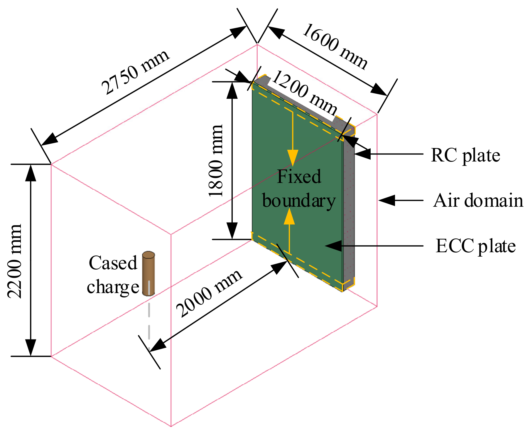
Figure 1. Numerical model of an ECC-protected RC plate subjected to a cased charge.
Buildings 16 02005 g001
Figure 2. Field test set-up [6]: (a) illustration; (b) schematic of RC plate dimensions.
Buildings 16 02005 g002
Figure 3. A schematic of the cased charge [6].
Buildings 16 02005 g003
Figure 4. Numerical model of RC plate subjected to cased charge blast: (a) overall view; (b) side view.
Buildings 16 02005 g004
Figure 5. Comparison of field test [6] and numerical simulation results of RC plate under combined loading: (a) front surface; (b) rear surface.
Buildings 16 02005 g005
Figure 6. Central displacements of RC plate: field test [6] and numerical model.
Buildings 16 02005 g006
Figure 7. Comparison between numerical and experimental acceleration time histories at the mid-span on the rear face of the RC slab.
Buildings 16 02005 g007
Figure 8. RC plate damage response with and without ECC layer protection: (a) front surface; (b) rear surface.
Buildings 16 02005 g008
Figure 9. Time history curve comparison of RC plate central displacement with and without ECC layer protection.
Buildings 16 02005 g009
Figure 10. Front surface damage of RC plate with different ECC layer thicknesses for protection.
Buildings 16 02005 g010
Figure 11. Front surface cratering area of RC plate with different ECC layer thicknesses for protection.
Buildings 16 02005 g011
Figure 12. Time history comparison of RC plate rear surface central displacement with different ECC layer thicknesses for protection.
Buildings 16 02005 g012
Figure 13. Damage response of RC slabs with different thicknesses under 10 mm ECC protection.
Buildings 16 02005 g013
Figure 14. Damage response of RC slabs with different reinforcement ratios under 10 mm ECC protection.
Buildings 16 02005 g014
Figure 15. Damage responses of unprotected RC slabs with varying thicknesses.
Buildings 16 02005 g015
Figure 16. Mid-span deflection–time history curves at the rear face of unprotected RC slabs with varying thicknesses.
Buildings 16 02005 g016
Figure 17. Damage response of RC plate with different levels of ECC protection: (a) front surface; (b) rear surface.
Buildings 16 02005 g017aBuildings 16 02005 g017b
Figure 18. Time history comparison of the RC plate rear surface central displacement with different strength ECC for protection.
Buildings 16 02005 g018
Figure 19. RC plate response and damage comparison with different ECC layer configurations for protection: (a) front surface; (b) rear surface.
Buildings 16 02005 g019aBuildings 16 02005 g019b
Figure 20. Time history comparison of RC plate central displacements with different ECC layer configurations: without protection, single-sided protection, and double-sided protection.
Buildings 16 02005 g020
Table 1. Tabulated η and λ of ECC.
λ η
0.00.0
8.0 × 10−60.85
2.4 × 10−50.97
4.0 × 10−50.99
5.6 × 10−51.0
7.2 × 10−50.99
8.8 × 10−50.97
3.2 × 10−40.5
5.2 × 10−40.1
5.7 × 10−40.0
1.00.0
100.0
1000.1
Table 2. Parameters of air.
ρ (kg/m3)C0C1C2C3C4C5C6E (GPa)
1.2900000.40.402.5 × 105
Table 3. Parameters of charge.
ρ (kg/m3)A (GPa)B (GPa)R1R2 ω E0 (GPa)
1630371.23.2314.150.950.37.0
Table 4. Parameters of No. 45 steel.
Johnson–CookGruneisen
A/MPaB/MPanmc ε ˙ 0 / s 1 c / m · s 1 s γ 0
3506000.3070.8040.072 × 10−446001.492.17
Table 5. Key parameters of C30 concrete.
R 0 (kg/m3)A0RSIZEUCFLCRATE
2400−3.0 × 10−50.3941.45 × 107 1
Note: Unit is MPa.
Disclaimer/Publisher’s Note: The statements, opinions and data contained in all publications are solely those of the individual author(s) and contributor(s) and not of MDPI and/or the editor(s). MDPI and/or the editor(s) disclaim responsibility for any injury to people or property resulting from any ideas, methods, instructions or products referred to in the content.