1. Introduction
Traditional Chinese architecture has developed over centuries into a unique structural system characterized by timber frameworks and sophisticated joint details, such as Mortise-Tenon connections and Dou-Gong brackets (tiered cantilevered bracket system). However, the inherent limitations of timber materials, such as susceptibility to decay, flammability, and insufficient durability under environmental or seismic actions, have resulted in the scarcity of well-preserved ancient buildings that remain today [
1]. With the growing attention to cultural heritage and urban development, Modern Chinese Traditional-style Buildings (MCTBs) constructed with steel frames to reproduce traditional architectural appearances have been widely adopted over the past two decades [
2]. The MCTBs represent a class of steel structural systems that incorporate traditional architectural appearance requirements within modern engineering design. From a structural mechanism perspective, MCTBs are essentially steel moment-resisting or braced frame systems. Their primary load-bearing mechanism is generally consistent with that of conventional steel structures specified in international seismic design codes, such as Eurocode 8 [
3] and ASCE 7 [
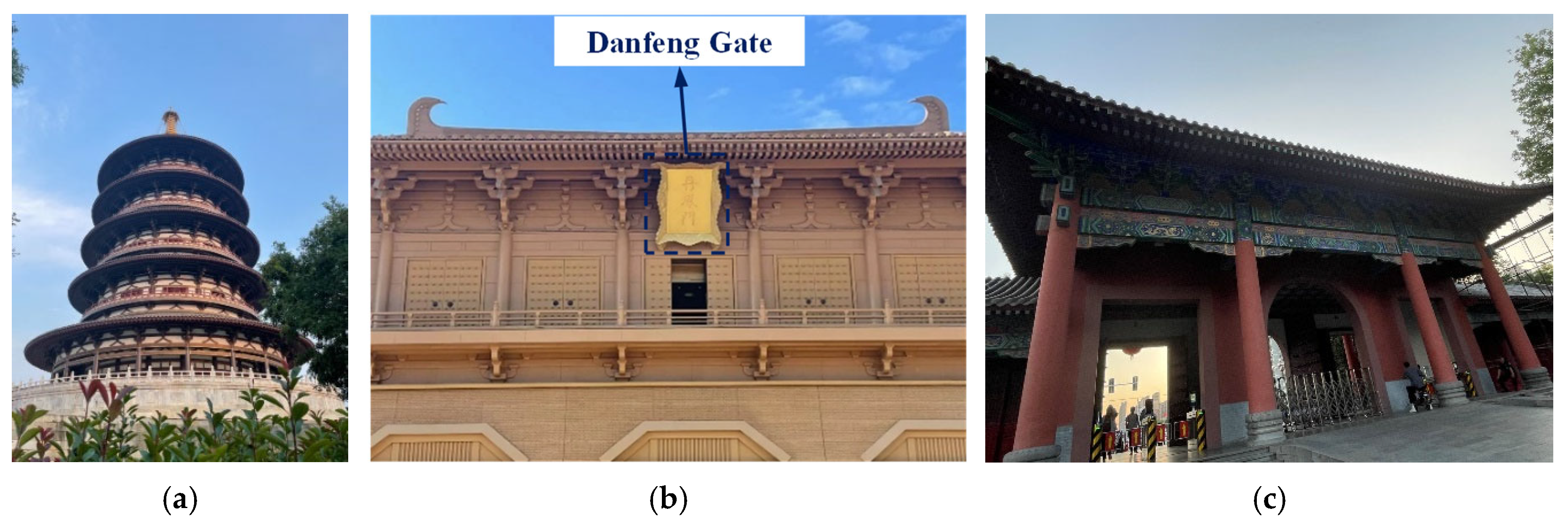
4]. The main distinction lies in the additional architectural constraints associated with traditional-style façade and decorative components (e.g., Que-Ti brackets and beam–column concealment requirements). These constraints restrict the layout and detailing of structural members and energy dissipation devices. Representative examples include public and cultural buildings such as the Heavenly Hall and Ming Hall in Hangzhou, as shown in
Figure 1. The typical structural configuration of MCTBs is shown in
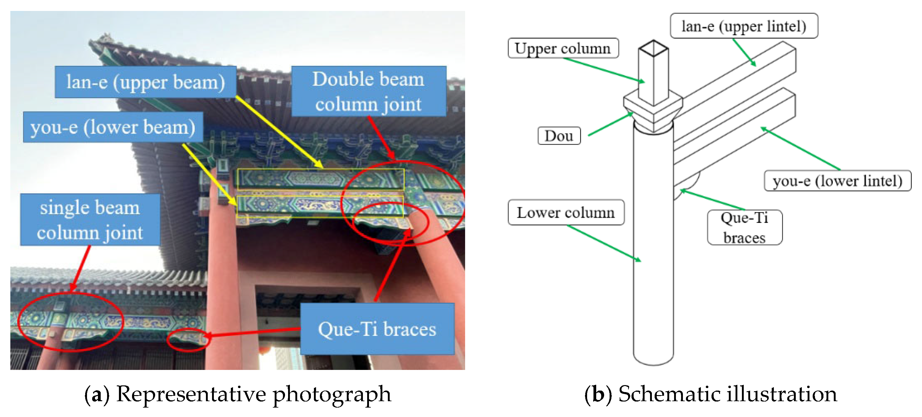
Figure 2, where irregular beam–column joints are formed due to the integration of transition columns and dual-beam systems. Moreover, timber components that originally contributed to energy dissipation and seismic resilience, such as Que-Ti braces (also referred to as sparrow braces), are often simplified into decorative elements in modern steel analogues. This simplification results in insufficient energy dissipation and potential weak regions at the joints [
5].
In China, MCTBs are widely distributed in historical cities such as Xi’an, Luoyang, Kaifeng, and Nanjing, where seismic fortification requirements are explicitly specified in the Chinese seismic design code and seismic zoning map. Among these representative regions, Xi’an is classified with a seismic fortification intensity of 8 degrees, while Luoyang, Kaifeng, and Nanjing are classified with 7 degrees, indicating considerable seismic risk. In addition, China has experienced several destructive earthquakes in recent decades, such as the 2008 Wenchuan earthquake and the 2013 Lushan earthquake, which further highlighted the importance of seismic resilience for public and cultural buildings. As many MCTBs serve as public facilities with high occupancy demands, ensuring their structural safety and seismic performance under earthquake actions is of great practical importance. Extensive experimental investigations on MCTBs have been conducted in recent years [
6]. The investigations covered key components, joints, subassemblies, and full-scale structures of traditional-style steel systems, including steel eave columns, beam–column joints, traditional-style steel frames, and steel pagoda models [
7,
8,
9,
10,
11,
12,
13]. Through combined experimental and numerical investigations, the seismic behavior of irregular steel joints in MCTBs was comprehensively examined. The results showed that although fully welded connections could satisfy the basic strength requirements, the geometric irregularities and abrupt sectional transitions of these joints caused severe stress concentrations at the welds between beam and column flanges. These stress concentrations led to tearing damage under cyclic loading and premature joint failure, significantly reducing the post-earthquake reparability of the structure.
In recent years, to improve the energy-dissipation performance of beam–column joints, researchers have proposed installing supplemental energy-dissipation devices in the joint region. The beam and column members are designed to remain essentially elastic under earthquake actions, while the replaceable damping components are intended to yield and dissipate energy preferentially. The seismic input energy is then dissipated through hysteretic deformation or velocity-dependent viscous damping effects. Relevant studies include self-centering PC frames with friction-dampers [
14], dry-connected rotational friction beam–column joints [
15,
16,
17], beam–column joints employing shape memory alloy (SMA) components [
18,
19], and concrete moment-resisting frame system with sector lead viscoelastic dampers [
20]. These studies consistently demonstrated that supplemental dampers can effectively improve the hysteretic behavior of joints, enhance load-bearing capacity and ductility, and significantly increase the overall energy-dissipation capacity of the structure.
Building upon this concept, previous studies proposed transforming the traditional Que-Ti brace region into a functional joint region for installing energy-dissipation components. In this way, originally decorative elements could partially regain structural functionality in modern systems. Based on this idea, a series of experimental studies on novel energy-dissipative joints have been carried out in different structural systems. In the steel traditional-style building system, six beam–column joint specimens were tested, including three with SMA bar-rotational friction dampers and three with SMA-shear friction dampers [
21,
22,
23]. The results indicated that the SMA composite friction devices provided both energy-dissipation and self-centering capability under minor earthquakes, and worked cooperatively with friction units under strong earthquakes, significantly enhancing joint strength and cumulative energy dissipation with flag-shaped hysteretic behavior. In addition, six beam–column joint specimens equipped with viscous dampers were tested in concrete traditional-style buildings [
24,
25]. Compared with the control joints without dampers, the specimens with viscous dampers exhibited notable improvements in load-bearing capacity, hysteretic stability, and displacement ductility, as well as a slower strength degradation, demonstrating the feasibility of enhancing seismic performance of traditional-style joints through external damping devices [
26]. Compared with existing studies on energy-dissipation joints in MCTBs, most previous research has focused on displacement-dependent mechanisms, such as SMA-based self-centering friction dampers and replaceable friction energy-dissipation devices. These systems typically aim to achieve either a self-centering response or damage-concentrated replaceable behavior, in which seismic energy is mainly dissipated through frictional sliding or recoverable SMA deformation. In contrast, viscous damper-based systems rely on velocity-dependent energy dissipation, and therefore do not significantly alter the intrinsic plastic hinge mechanism of beam-end regions. Instead, they provide supplemental damping to improve hysteretic stability and energy dissipation capacity while maintaining the original global failure mode governed by strong-column-weak-beam behavior.
Building upon previous experimental investigations, this study proposes a novel seismic-resilient joint system for MCTBs by integrating viscous dampers into the Que-Ti brace region of irregular beam–column joints. Cyclic dynamic loading tests were conducted on a series of single and double beam–column joint specimens, and the results provide detailed insights into the failure modes, hysteretic behavior, load-carrying capacity, and energy dissipation characteristics of the proposed joints. In addition, a displacement-frequency coupled loading protocol was developed to capture the velocity-dependent behavior of viscous dampers under cyclic excitation, enabling a more realistic simulation of damper performance under seismic-like loading conditions. Based on the experimental results, a validated three-dimensional finite element model was established. A comprehensive parametric study was then performed to investigate the influence of key design variables, including column axial compression ratio, damping coefficient, and damper length, on the mechanical and energy-dissipation responses of the joints. This study provides a systematic framework for structural design, experimental evaluation, and numerical simulation of energy-dissipation joints, and offers guidance for the application of viscous dampers in traditional-style steel structures.
4. Numerical Analysis of Steel Resilient Joints in MCTBs
4.1. Finite Element Models
An implicit dynamic solver was adopted to ensure numerical stability and accuracy under cyclic loading with moderate strain rates, while avoiding excessive computational cost. The geometric dimensions of the numerical models were identical to those of the experimental specimens, and all components were modeled using three-dimensional solid elements. All steel members were discretized with C3D8R elements.
Welded connections and inter-component interfaces (e.g., internal diaphragms to the column wall and damper brackets to member surfaces) were simulated using tie constraints. Weld fracture was not considered in the numerical models. A reference point was defined at the column base, where a pinned boundary condition was applied to represent the fixed hinge support. At the column top, a loading pad was introduced and constrained as a rigid body. Axial force and horizontal sinusoidal loading were applied through the corresponding reference point. The loading protocol and boundary conditions were kept consistent with those adopted in the experimental program. Since damage in the tests was mainly concentrated in the beam-end plastic hinge regions, a refined mesh with an element size of 30 mm was adopted in these areas. A coarser mesh with an element size of 60 mm was used in the remaining regions to improve computational efficiency.
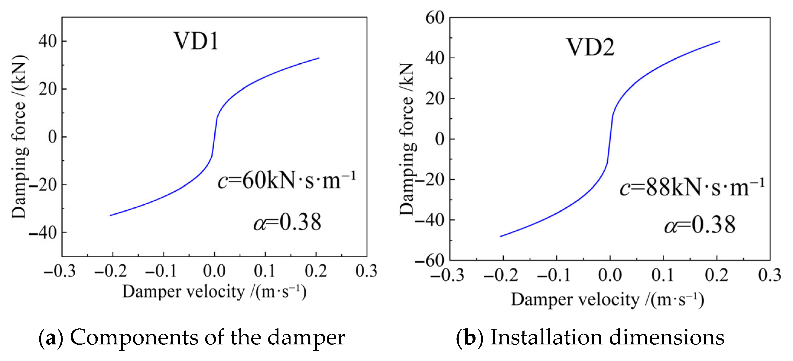
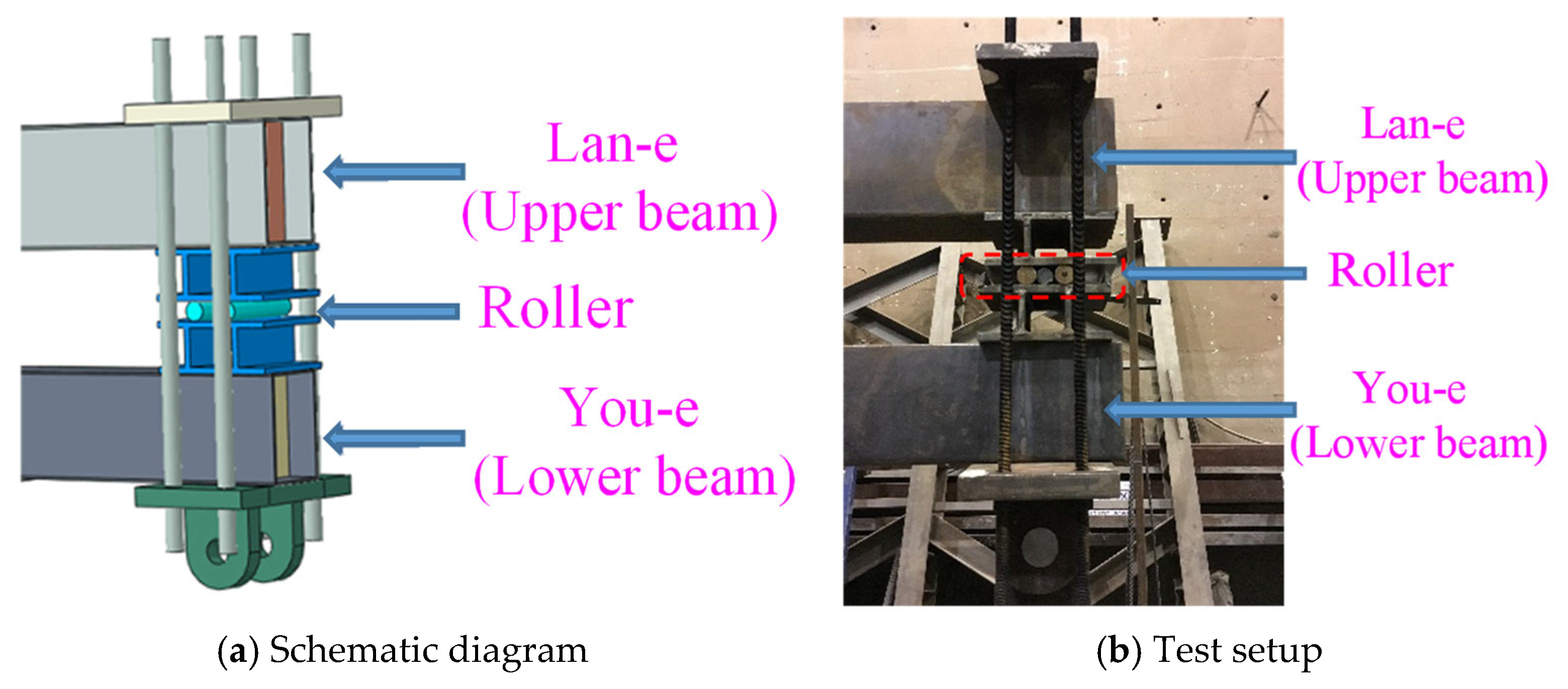
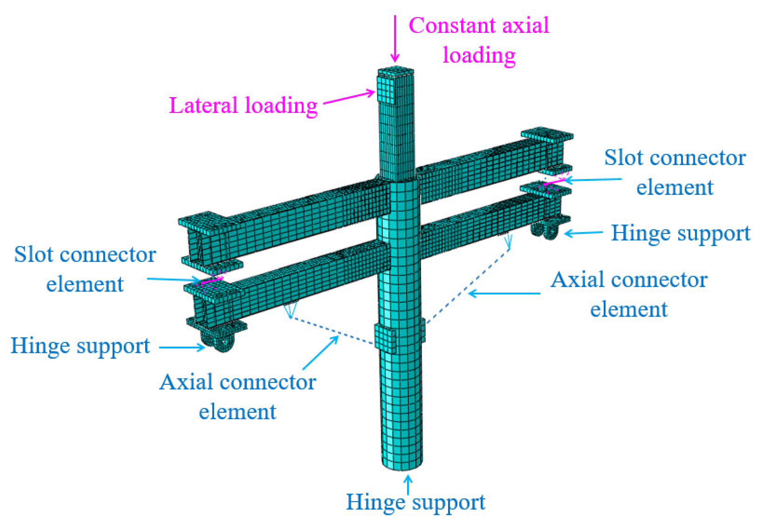
Two key modeling strategies were incorporated into the finite element model. First, a double-beam connector was introduced to represent the coupled mechanical behavior between the upper and lower beams. Second, replaceable viscous dampers were incorporated at critical joint locations to capture their contribution to energy dissipation. The double-beam connector was modeled using the Slot connector element in ABAQUS. End plates were first introduced at the beam ends and defined as rigid bodies. These plates were tied to the upper and lower beam ends through reference points. A Slot connector element was then inserted between the reference points of the two central end plates. This element restrained relative motion in the U2 and U3 directions while allowing horizontal sliding in the U1 direction. The connector was capable of transmitting vertical force while retaining rotational degrees of freedom. A rigid reference point was defined at the lower end of the connector and assigned a pinned boundary condition to simulate the experimental support configuration. The viscous dampers were modeled using axial connector elements in ABAQUS. Rigid pads were introduced at the damper connection locations and defined as rigid bodies through reference points. These reference points were tied to the corresponding beam and column surfaces. An Axial connector element was inserted between the two reference points and assigned a velocity-dependent damping behavior. The force-velocity relationship was defined based on the manufacturer-provided mechanical test data, with the damping exponent α uniformly taken as 0.38. The fitted damper constitutive relationship was derived from the data shown in
Figure 5. The overall finite element model is illustrated in
Figure 12.
It should be noted that several simplifying assumptions were adopted in the present finite element model. Welded connections and inter-component interfaces were modeled using tie constraints, and weld fracture or material separation was not explicitly considered. This modeling strategy assumes that the welds possess sufficient strength and ductility to maintain integrity during the loading process. It also assumes that the global structural response is primarily governed by the formation of plastic hinges in the beam-end regions. Therefore, the proposed finite element model is mainly applicable to the analysis of the global hysteretic behavior, load-carrying capacity, and energy-dissipation performance of irregular steel joints prior to severe fracture or instability. The model is not intended to capture local failure mechanisms such as weld cracking, fracture propagation, or low-cycle fatigue damage. These approaches have been widely adopted in finite element simulations of steel beam–column joints and traditional-style steel structures under cyclic loading. They have been shown to provide reliable predictions of global structural response while maintaining computational efficiency [
12,
39].
4.2. Validation of Simulation Results
4.2.1. Stress Distribution
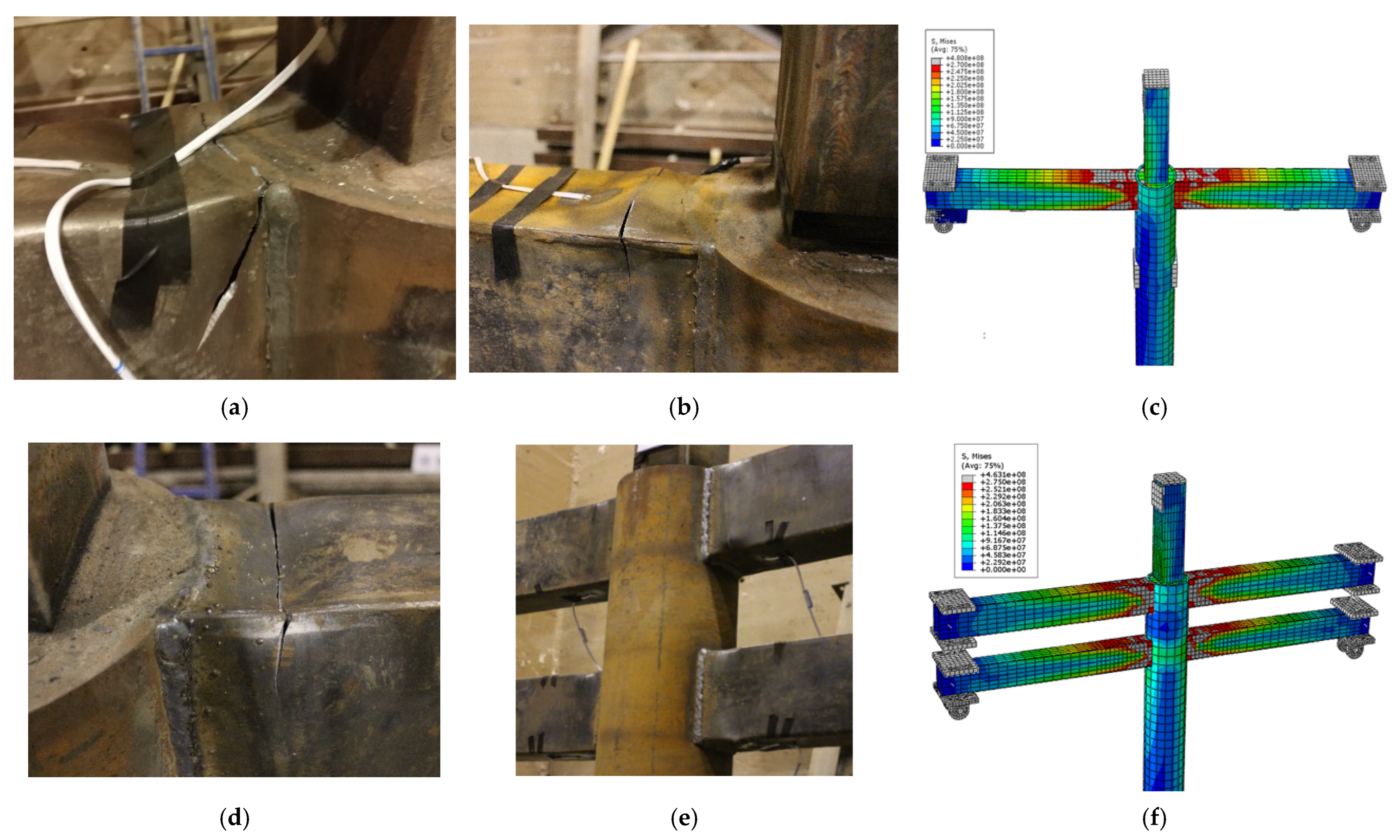
Figure 13 compares the experimentally observed damage patterns with the stress distribution predicted by the finite element analysis at representative loading stages. At the onset of yielding, both the experimental observations and the numerical results indicate that yielding initiated at the upper and lower flanges near the beam end. As the loading amplitude increased, the yielded region progressively expanded toward the beam-end plastic hinge zone, which is consistent with the expected flexural-dominated failure mechanism of the joint. With further increase in displacement demand, a fully developed plastic zone formed at the beam end in the numerical model, in agreement with the severe local deformation and damage concentration observed in the tests. Overall, the predicted stress distribution and the evolution of the plastic regions closely matched the experimental deformation and failure characteristics. These results demonstrate that the proposed finite element model can reasonably reproduce the stress transfer path and damage development process of the joint.
4.2.2. Comparison of Hysteretic Curves of Specimens
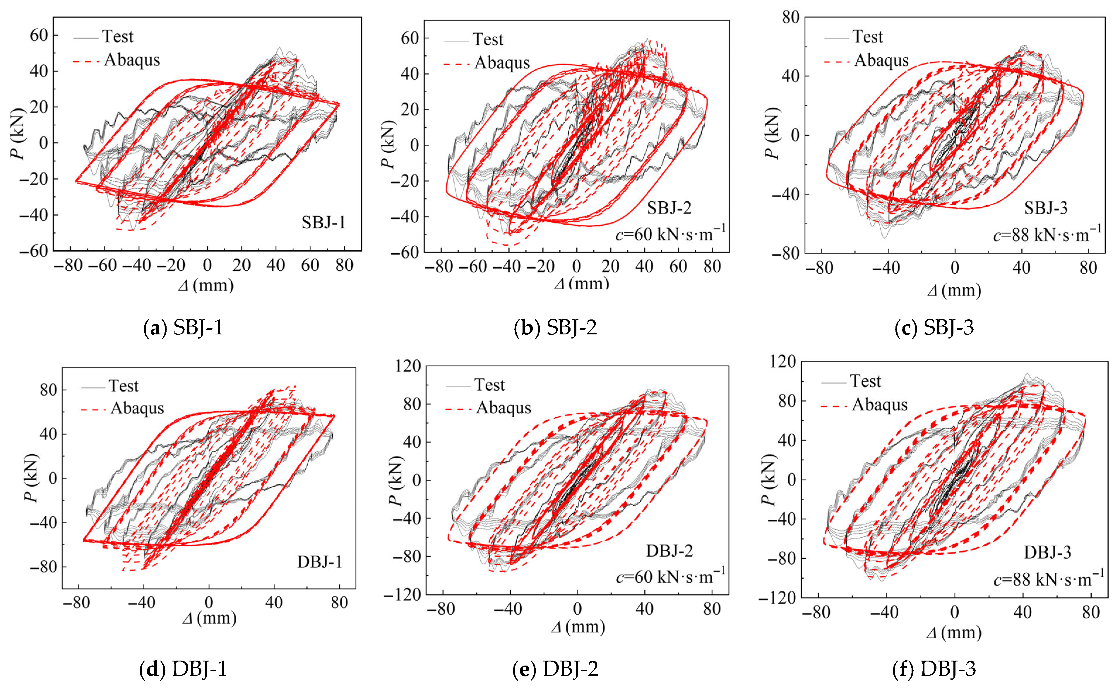
Figure 14 compares the simulated and experimental lateral load–displacement hysteretic responses measured at the column top.
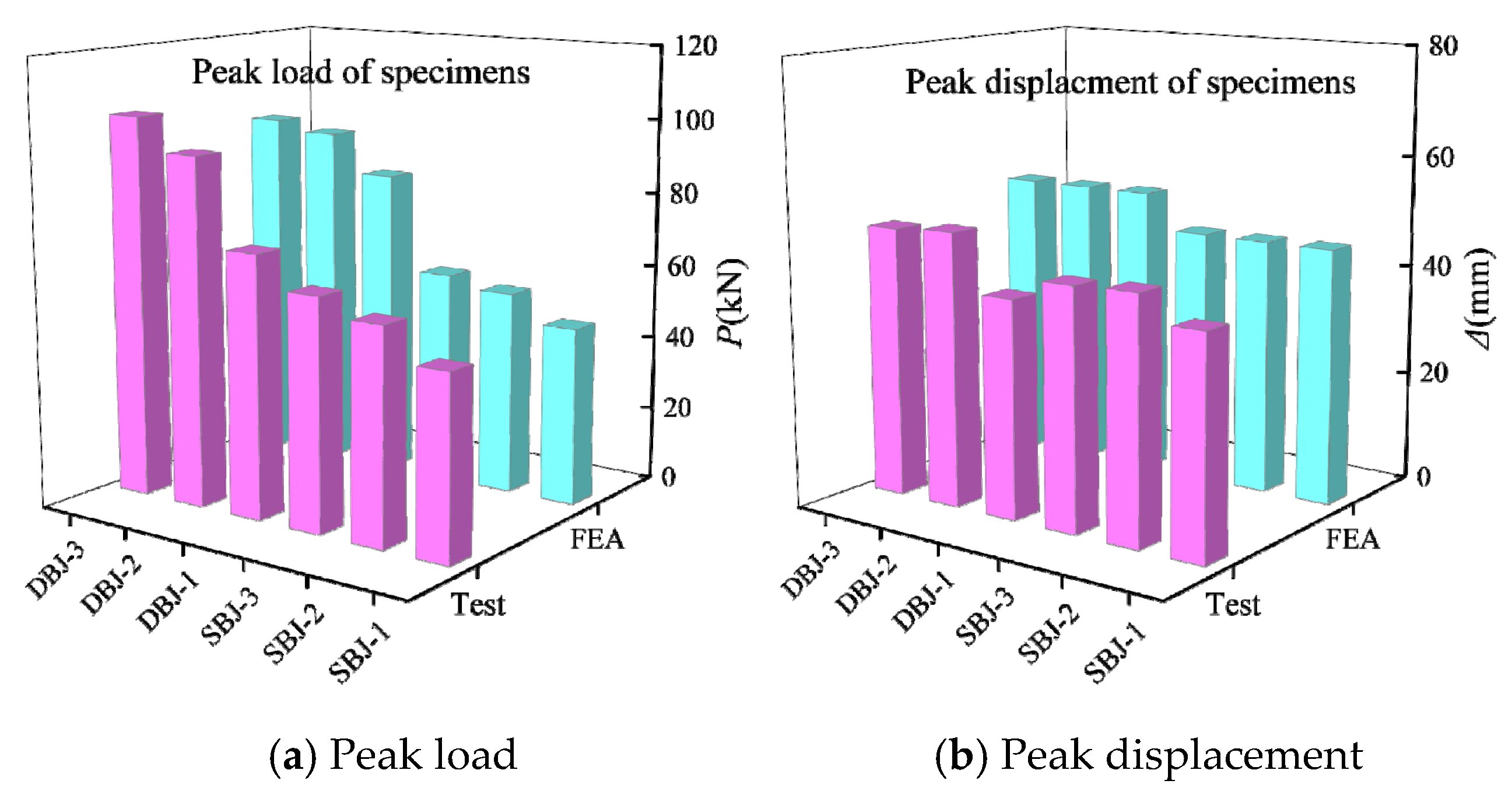
Figure 15 summarizes the comparison of peak load values for all specimens. At the initial loading stage, the numerical simulations exhibited good agreement with the experimental hysteretic curves in terms of stiffness and response trend. As the loading progressed toward the peak and post-peak stages, the simulated hysteretic loops became slightly fuller than those observed in the experiments. This indicates a higher predicted energy dissipation capacity. The deviation of peak load between numerical and experimental results is generally within 10%, indicating satisfactory predictive accuracy of the finite element model. This discrepancy can be primarily attributed to material damage mechanisms observed in the tests, such as weld cracking and tearing of the beam-end base material after reaching the ultimate state. These damage mechanisms were not explicitly modeled in the finite element analysis. Despite these differences in hysteretic loop shape, the simulations remained highly consistent with the experimental results in terms of maximum displacement, load-carrying capacity, and overall deformation evolution. These findings demonstrate that the finite element model is capable of reasonably capturing the global hysteretic behavior and deformation characteristics of steel joints equipped with viscous dampers in MCTBs.
4.2.3. Comparison of Hysteretic Curves of Dampers
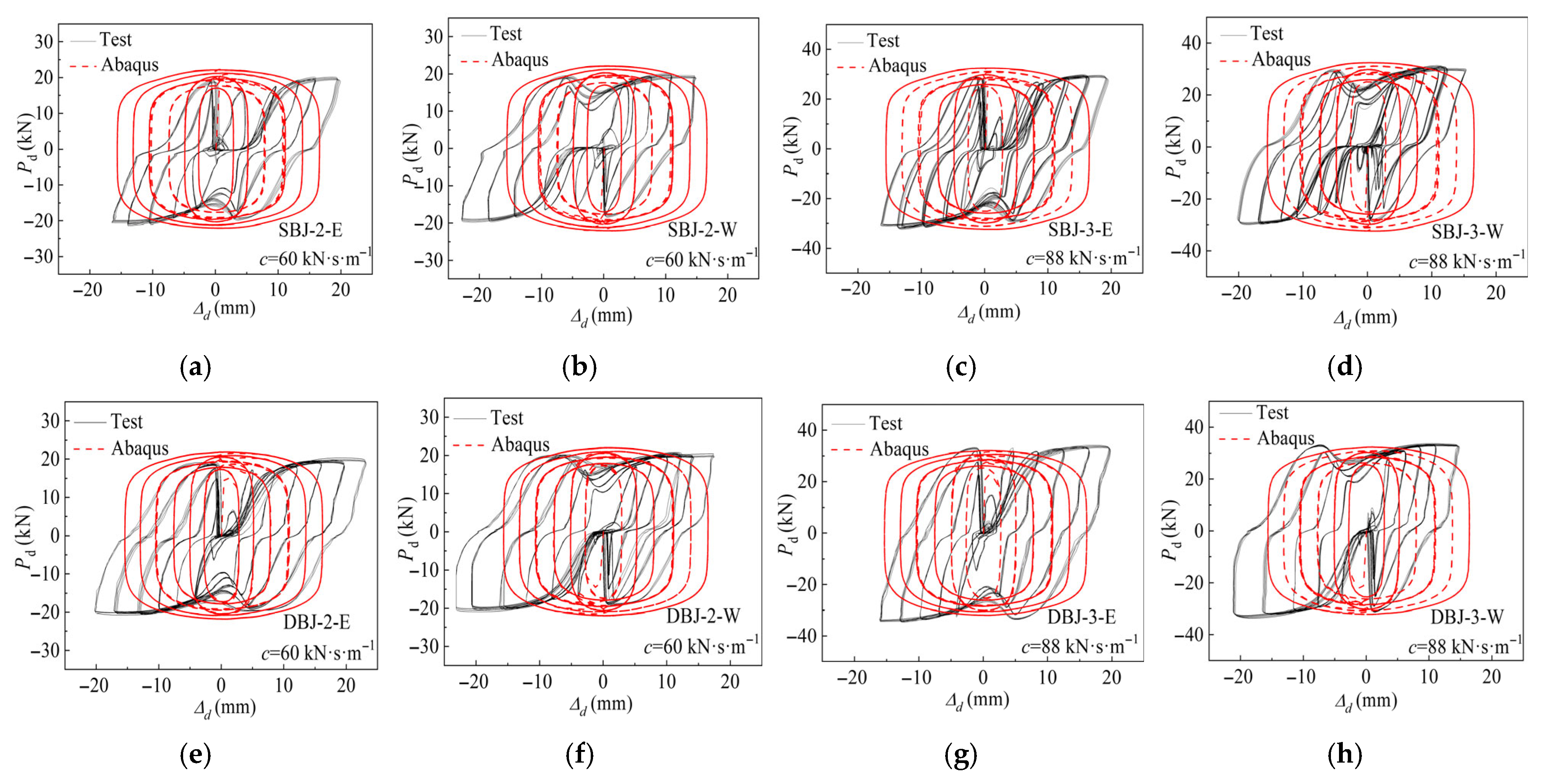
Accurate representation of the mechanical behavior of viscous dampers is critical for the numerical simulation of damper-equipped joints. To validate the modeling strategy, the damper force displacement hysteretic responses obtained from the numerical simulations were compared with the experimental results, as shown in
Figure 16 and
Figure 17. E and W denote the east-side and west-side dampers, respectively. In this study, the damper force
Pd refers to the output force generated during the piston motion of the viscous damper, while the displacement
Δd represents the relative axial displacement between the two damper ends under tension or compression, corresponding to elongation or shortening.
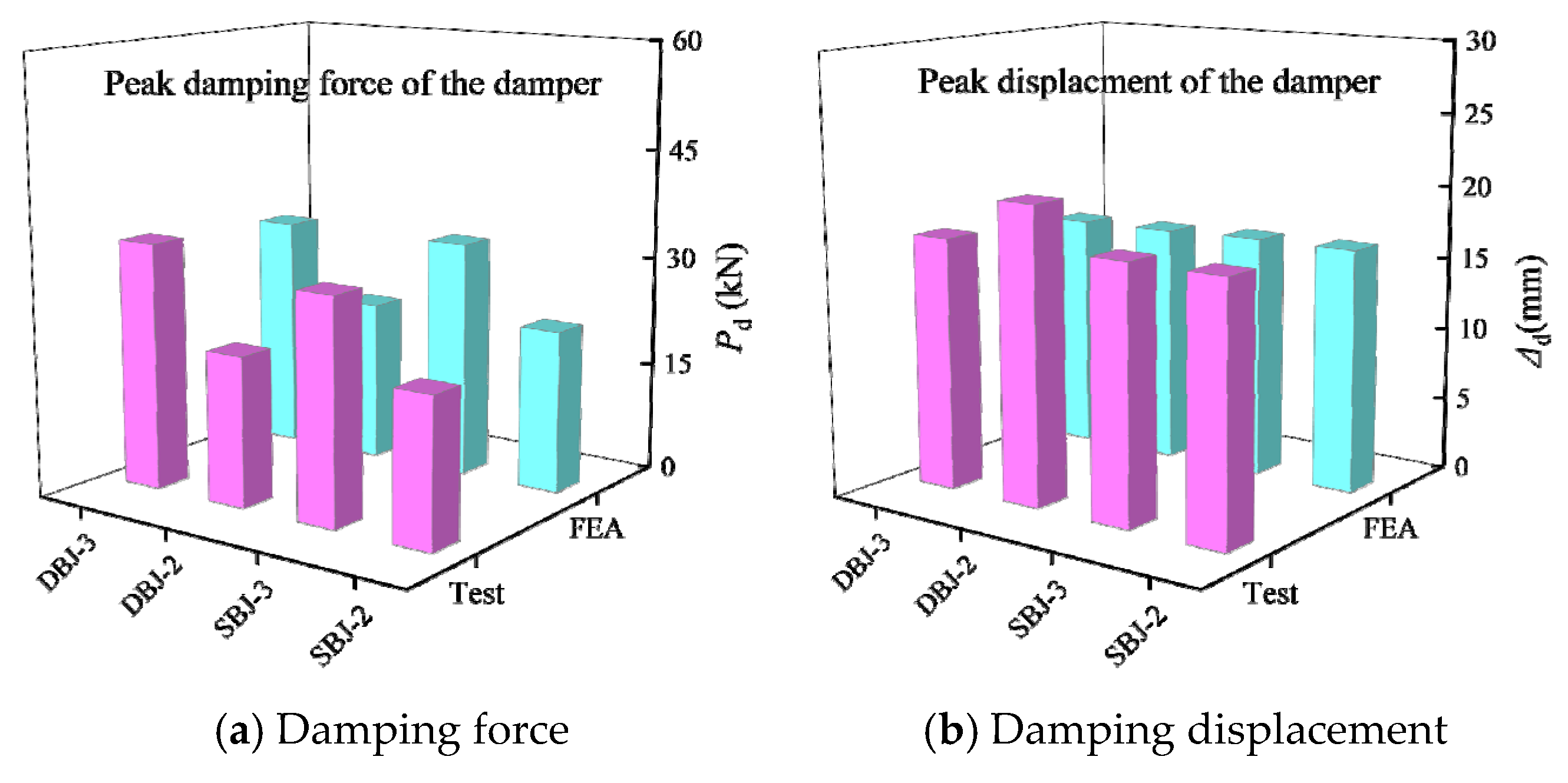
The experimentally obtained hysteretic curves exhibit a slight inclination, whereas the numerical responses are relatively symmetric. This difference is mainly attributed to the instantaneous stiffness effect caused by compression of the damping medium during experimental loading. In addition, a noticeable indentation near the zero-displacement region is observed in the experimental curves. This phenomenon can be explained by short pauses between successive loading cycles. During these pauses, the relative piston velocity approached zero, resulting in a temporary reduction in damper force. In contrast, continuous loading without pauses was adopted in the numerical simulations, leading to smooth and continuous hysteretic loops near the origin. Moreover, the numerical hysteretic curves appear fuller and show no evident translation along the displacement axis. This is because assembly clearances at the damper end connections and between structural components were not considered in the finite element model. In contrast, slight initial slippage occurred in the experiments due to these clearances. Despite these local differences in hysteretic shape, the numerical and experimental results show good agreement in key engineering parameters, including the maximum damper force and the maximum damper displacement. This comparison confirms that the numerical model can reasonably reproduce the mechanical response of viscous dampers under cyclic loading.
4.3. Parametric Design
To further investigate the influence of critical parameters on the seismic performance of irregular steel joints equipped with viscous dampers in MCTBs, a series of parametric studies were conducted based on the established numerical model. The effects of the column axial compression ratio, viscous damping coefficient and damper length were systematically examined in terms of joint load-carrying capacity and energy dissipation performance.
4.3.1. Effect of Column Axial Compression Ratio
(1) Load-carrying capacity of joints
Numerical analyses were conducted by varying the column axial compression ratio
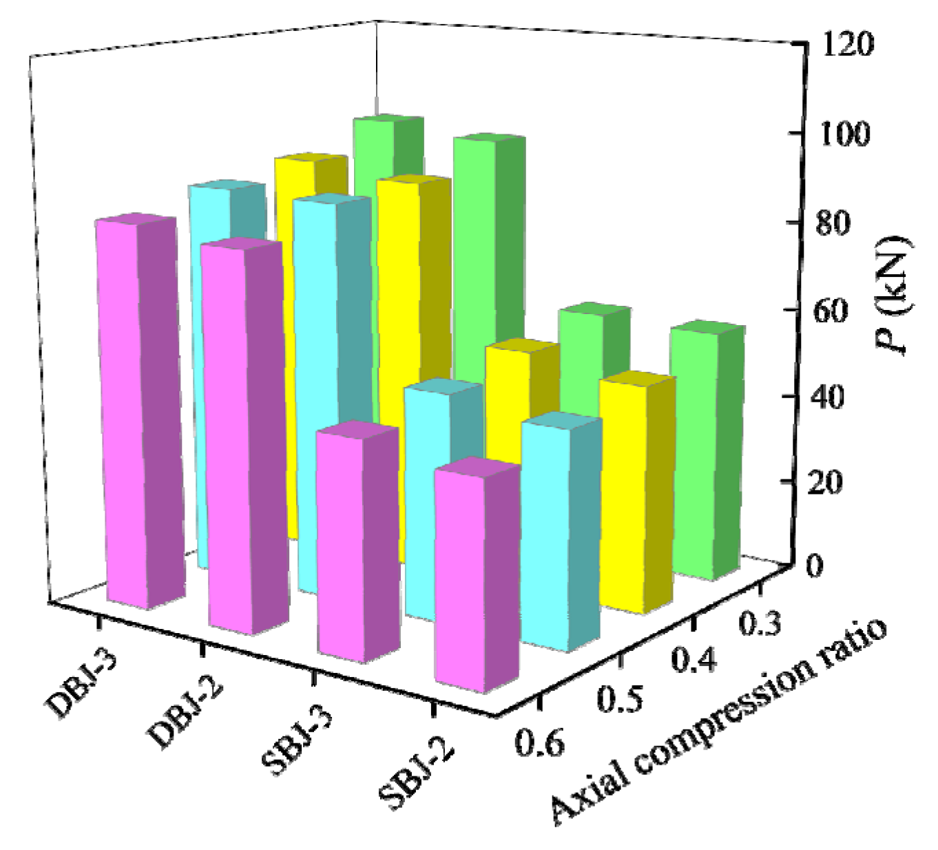
n to 0.3, 0.4, 0.5, and 0.6, while all other parameters were kept constant. The peak load capacities under different conditions are presented in
Figure 18. The results show that the peak load capacity of the joints generally decreases with increasing axial compression ratio. Compared with the cases of
n = 0.4, 0.5, and 0.6, the peak load of the SBJ-2 joint increased by 7.86%, 13.93%, and 20.23%, respectively, when
n = 0.3, while the corresponding increases for the SBJ-3 joint were 5.94%, 12.36%, and 18.47%. For the DBJ-2 joint, the peak load increased by 8.77%, 7.87%, and 11.81%, respectively, whereas the DBJ-3 joint exhibited increases of 8.43%, 7.62%, and 11.64%. These results indicate that the axial compression ratio has a clear influence on the joint load-carrying capacity. Higher axial compression ratios are associated with reduced peak load capacity.
(2) Energy dissipation of joints
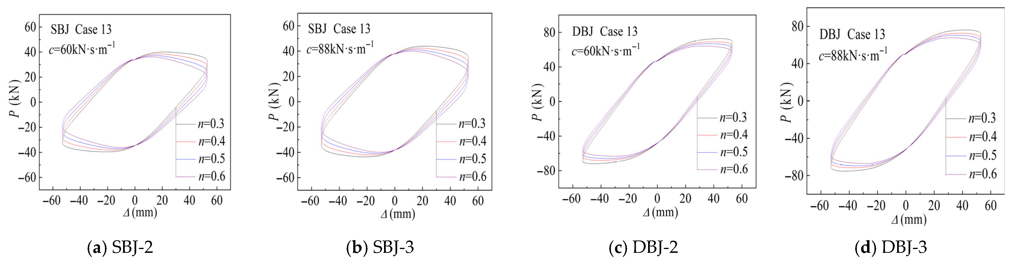
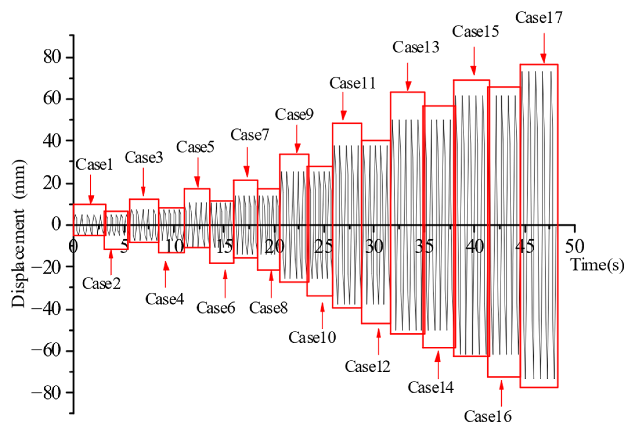
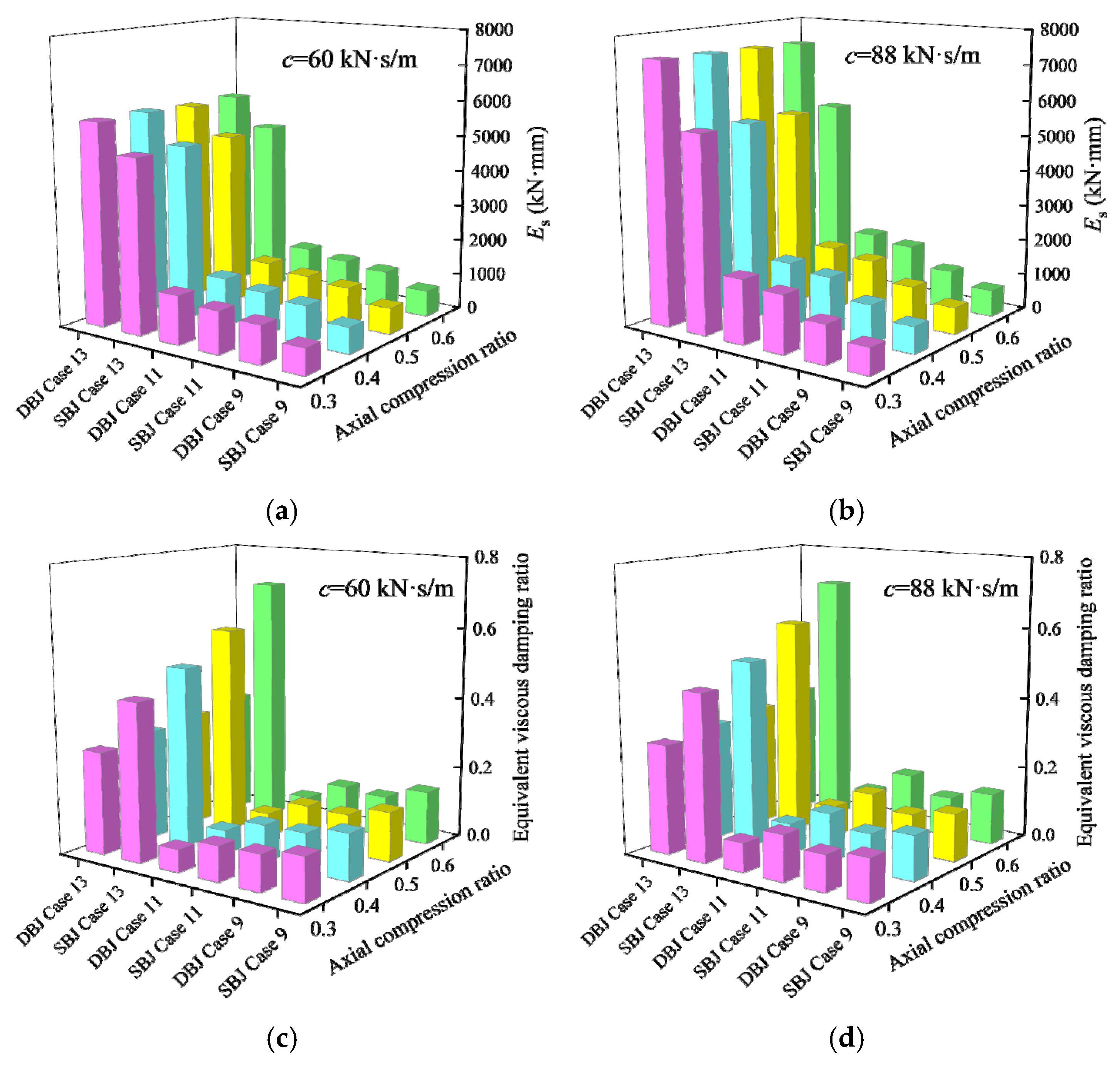
Figure 19 compares the hysteretic responses corresponding to the third loading cycle of loading case 13 under different axial compression ratios. The associated hysteretic energy dissipation and equivalent viscous damping coefficients are summarized in
Figure 20. The hysteretic energy dissipation is defined as the enclosed area of each hysteretic loop. As shown in
Figure 19, increasing the axial compression ratio causes the hysteretic loops to exhibit a slight inclination toward the displacement axis, indicating a gradual reduction in joint stiffness. Nevertheless, the enclosed hysteretic areas remain nearly constant, and only marginal variations are observed in the equivalent viscous damping coefficient. These results indicate that the axial compression ratio has a limited influence on the energy dissipation capacity of the joints. This behavior can be attributed to the adopted “strong-column–weak-beam” design philosophy, under which the failure mode remains unchanged and is consistently governed by the formation of plastic hinges at the beam ends. Furthermore, the deformation of the viscous dampers is primarily controlled by the flexural deformation of the beam ends. Consequently, the relative displacement and force response of the dampers are only weakly affected by variations in the column axial load.
The relatively unchanged hysteretic energy dissipation indicates that the plastic hinge rotation capacity at the beam ends is not significantly affected by the axial compression ratio under the adopted strong-column–weak-beam mechanism. Therefore, the energy dissipation behavior is primarily governed by beam-end plastic hinge rotation rather than the axial force level.
(3) Mechanical response of viscous dampers
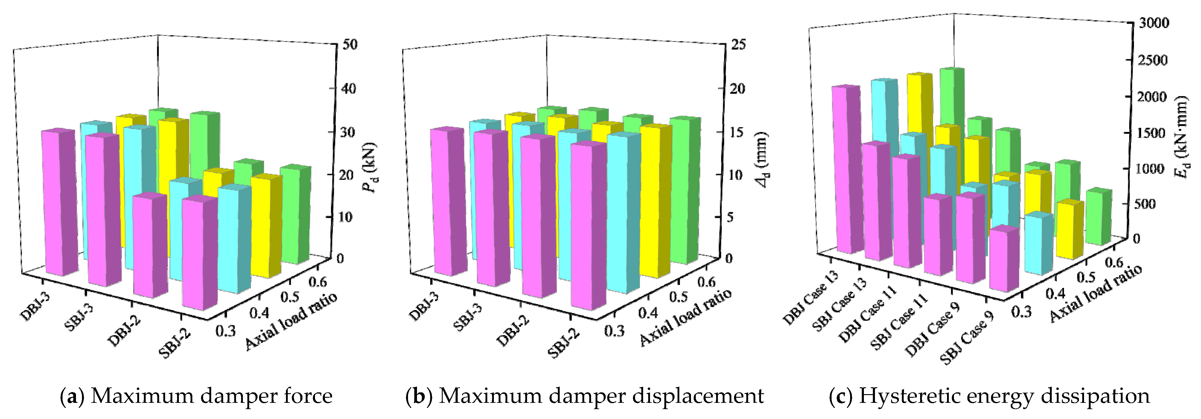
The maximum damper force, maximum damper displacement, and hysteretic energy dissipation under loading conditions 9, 11, and 13 for different column axial compression ratios are summarized in
Figure 21. The results show that changes in the axial compression ratio have a negligible influence on the mechanical response of the viscous dampers. Specifically, the maximum damper force, damper displacement, and hysteretic energy dissipation remain nearly constant as the axial compression ratio increases. This behavior is attributed to the limited effect of axial compression on the displacement demand at the beam ends, which governs the relative deformation of the dampers. As a result, the force response and energy dissipation capacity of the viscous dampers are not significantly affected by variations in the column axial load.
4.3.2. Effect of Damping Coefficient of Dampers
(1) Load-carrying capacity of joints
Parametric analyses were performed by varying the damping coefficient c as 30, 60, 88, and 120 kN·s·m
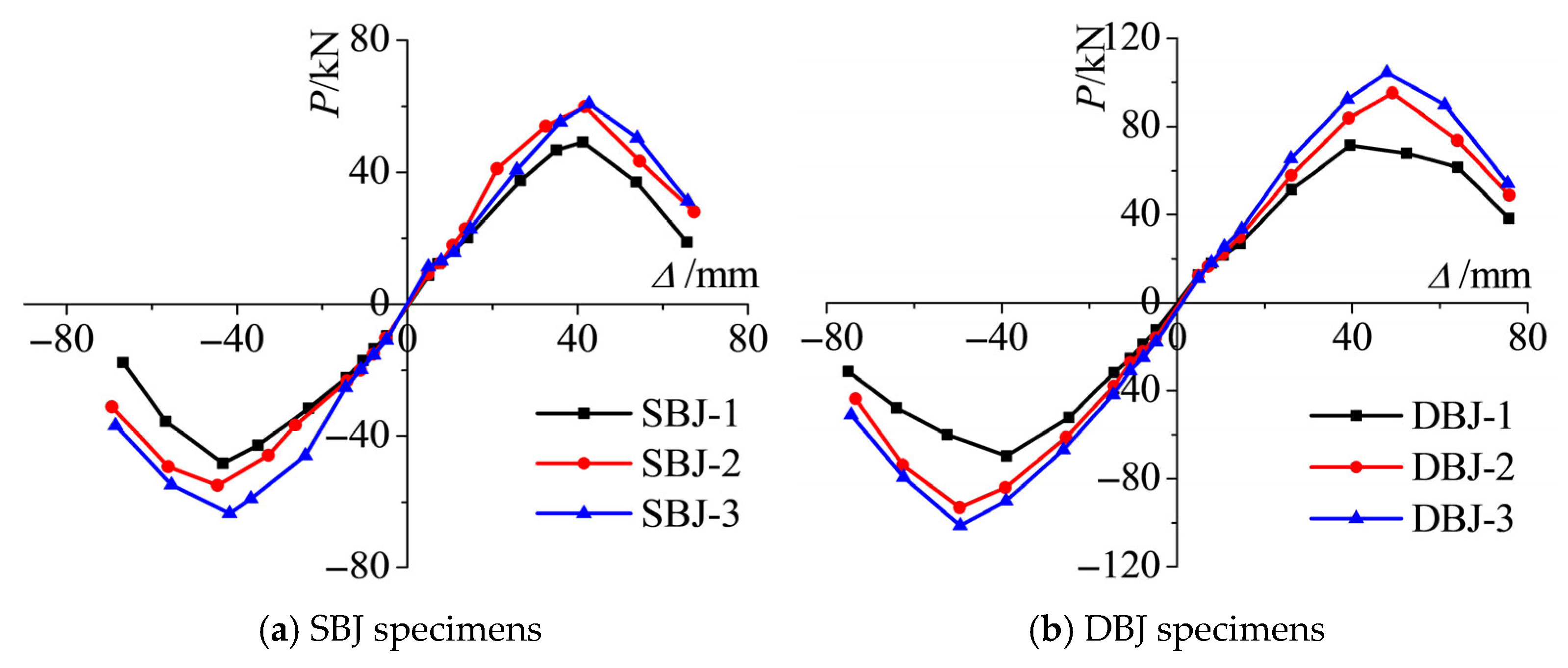
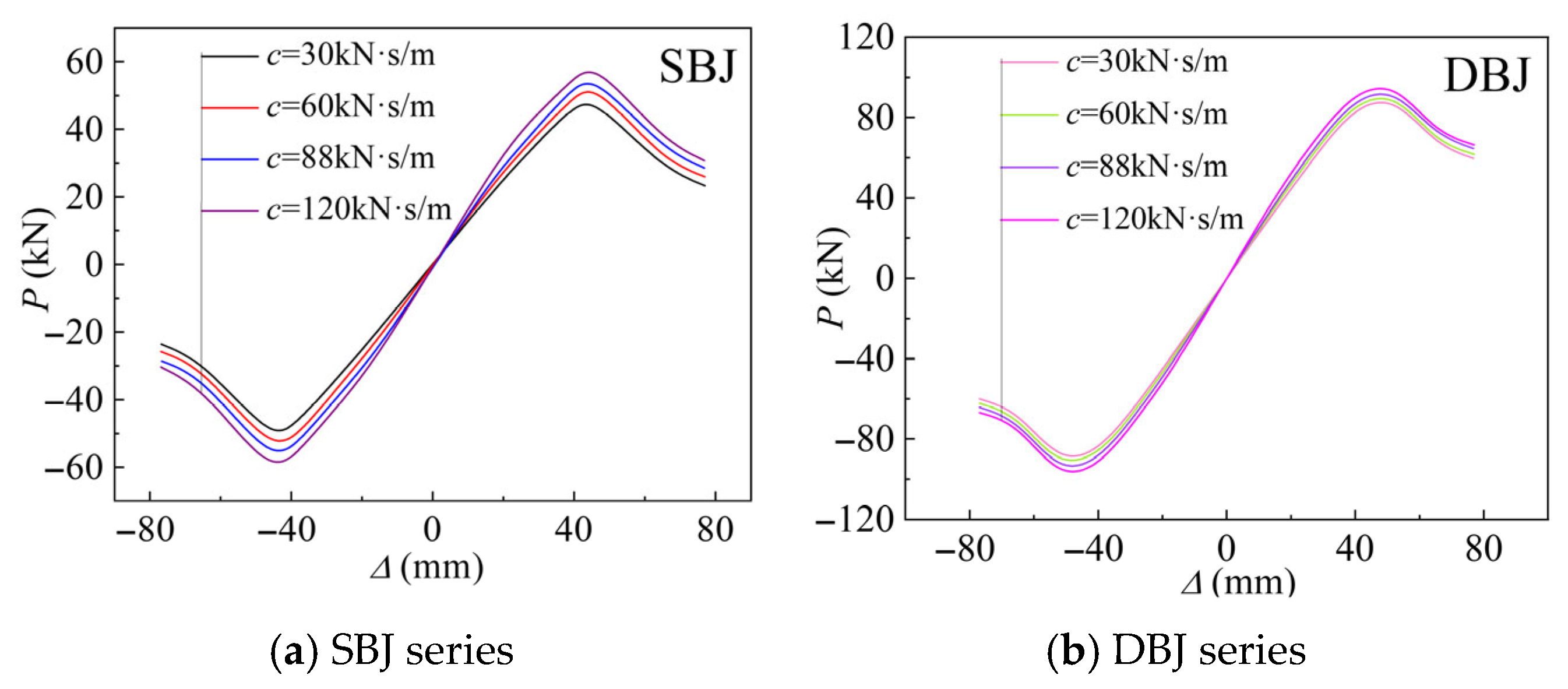
−1, while the damping exponent was maintained at 0.38. Backbone curves were derived from the column-top load displacement hysteretic responses, as illustrated in
Figure 22. Comparisons of the peak load and the corresponding displacement between the numerical results and the experimental data are presented in
Figure 23. The results indicate that the peak load of the specimens increases progressively with increasing damping coefficient. A moderate enhancement in initial stiffness was also observed. At approximately identical peak displacement levels, compared with the specimen with
c = 30 kN·s·m
−1, the peak load of the SBJ series increased by 8.64%, 18.12%, and 22.11% for
c = 60, 88, and 120 kN·s·m
−1, respectively. In contrast, the corresponding increases for the DBJ series were relatively smaller, reaching 2.28%, 5.11%, and 8.53%, respectively. This trend is attributed to the velocity-dependent nature of viscous dampers. Higher damping coefficients generate larger resisting forces at identical deformation rates, thereby increasing the apparent stiffness and peak load capacity of the joint system.
(2) Energy dissipation capacity of joints
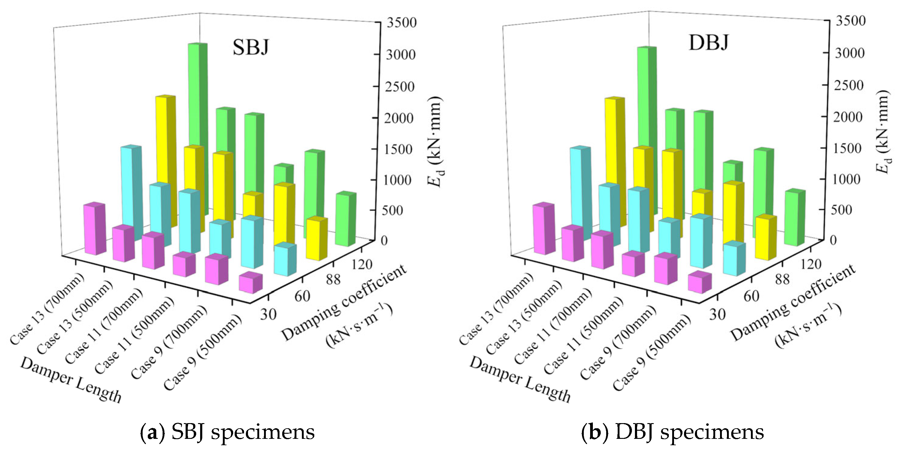
The third hysteretic loops under loading cases 9, 11, and 13 were extracted for comparative analysis. The corresponding hysteretic energy dissipation and equivalent viscous damping coefficients were calculated, as shown in
Figure 24. The results indicate that, with increasing damping coefficient of the viscous damper, the hysteretic loops became progressively fuller, accompanied by an evident enlargement of the enclosed area. The hysteretic energy dissipation of the specimens increased with increasing damping coefficient. Moreover, when identical increments in damping coefficient were applied, the corresponding increases in hysteretic energy dissipation remained approximately consistent. The increase in hysteretic energy dissipation is governed by the velocity-dependent energy absorption mechanism of viscous dampers. Higher damping coefficients directly enhance the rate-sensitive resisting force and energy dissipation capability under cyclic loading.
(3) Performance of viscous dampers
The maximum damper force, maximum damper displacement, and hysteretic energy dissipation of the viscous dampers under loading cases 9, 11, and 13 were extracted for different damping coefficients. The corresponding results are presented in
Figure 25 and
Figure 26. The results show that both the maximum damper force and the hysteretic energy dissipation increase markedly with increasing damping coefficient, whereas the variation in damper displacement remains relatively small. This behavior can be attributed to the consistent loading protocol and the essentially unchanged global structural response. As a result, the displacement amplitude of the dampers is mainly governed by structural deformation and is therefore less sensitive to variations in the damping coefficient. In addition, comparable values of maximum damper force, maximum damper displacement, and hysteretic energy dissipation are observed for the SBJ and DBJ series specimens, suggesting that the viscous dampers provide similar energy dissipation effectiveness under different joint configurations. The damper response is primarily controlled by structural kinematics, while the damping coefficient mainly affects the force level rather than the displacement demand. This indicates a force-controlled rather than displacement-controlled energy dissipation mechanism in the system.
4.3.3. Damping Device Length
(1) Load-carrying capacity of joints
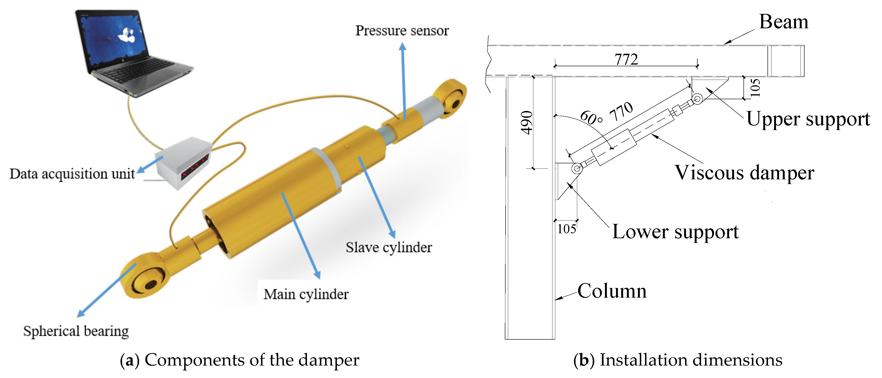
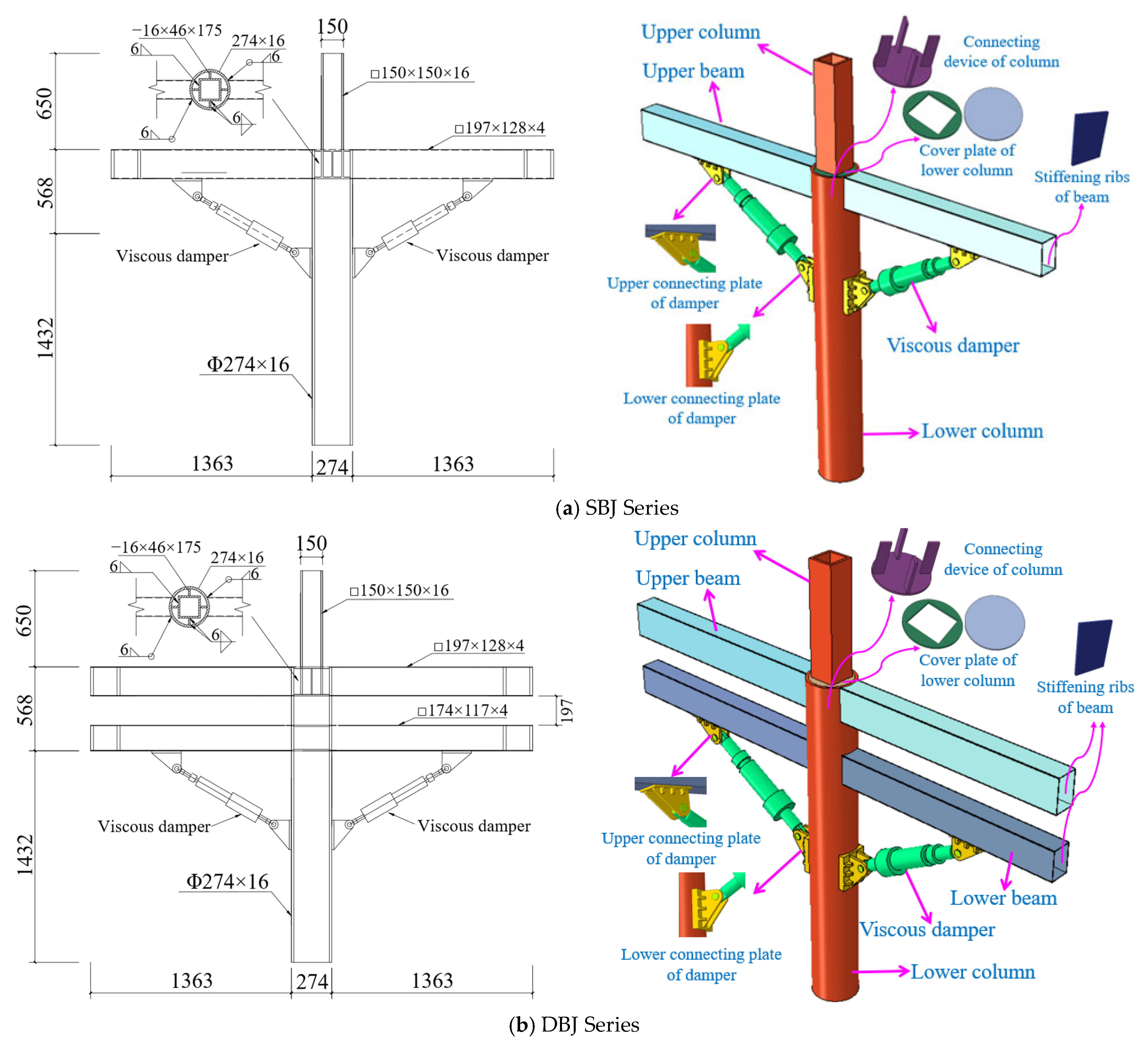
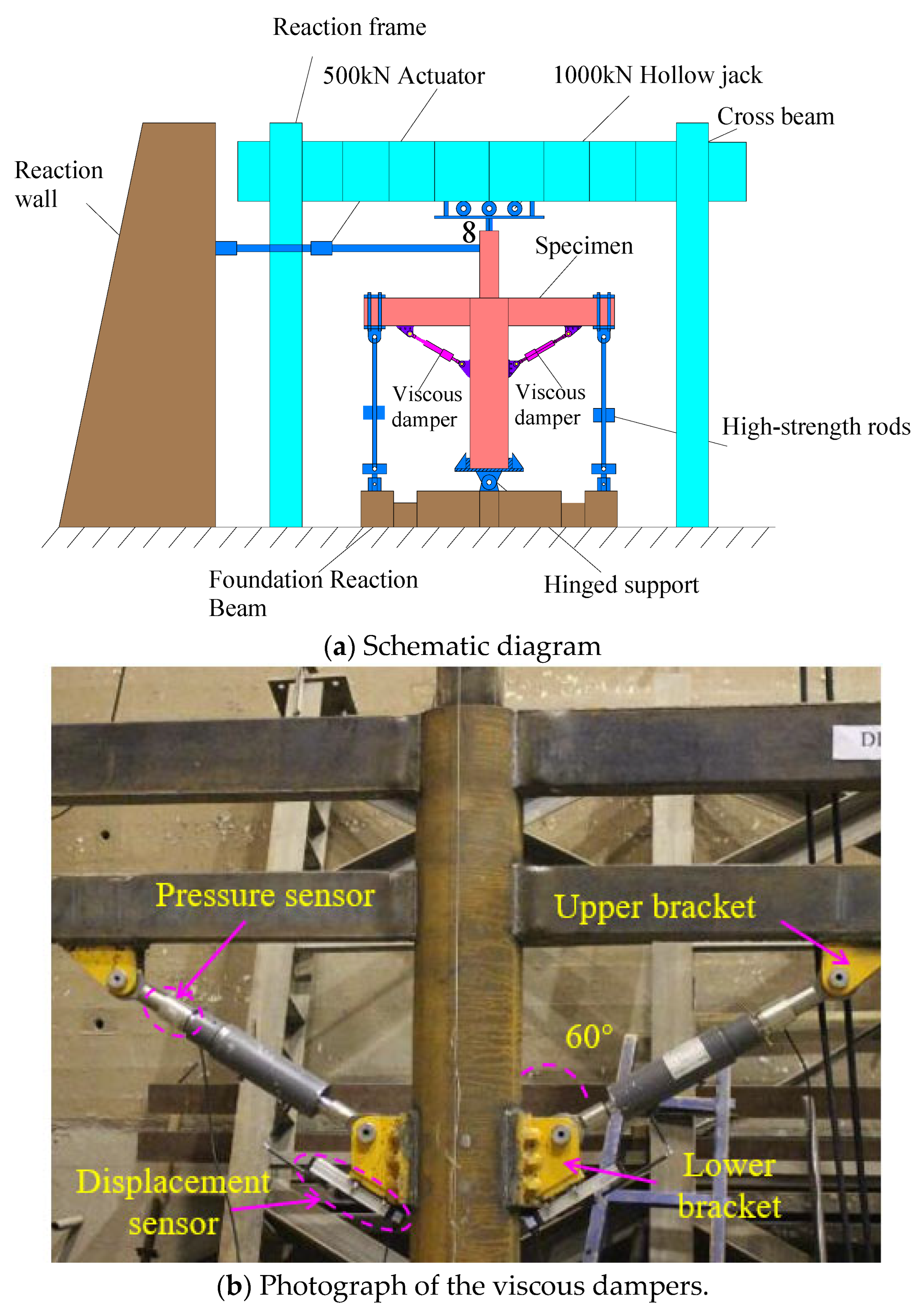
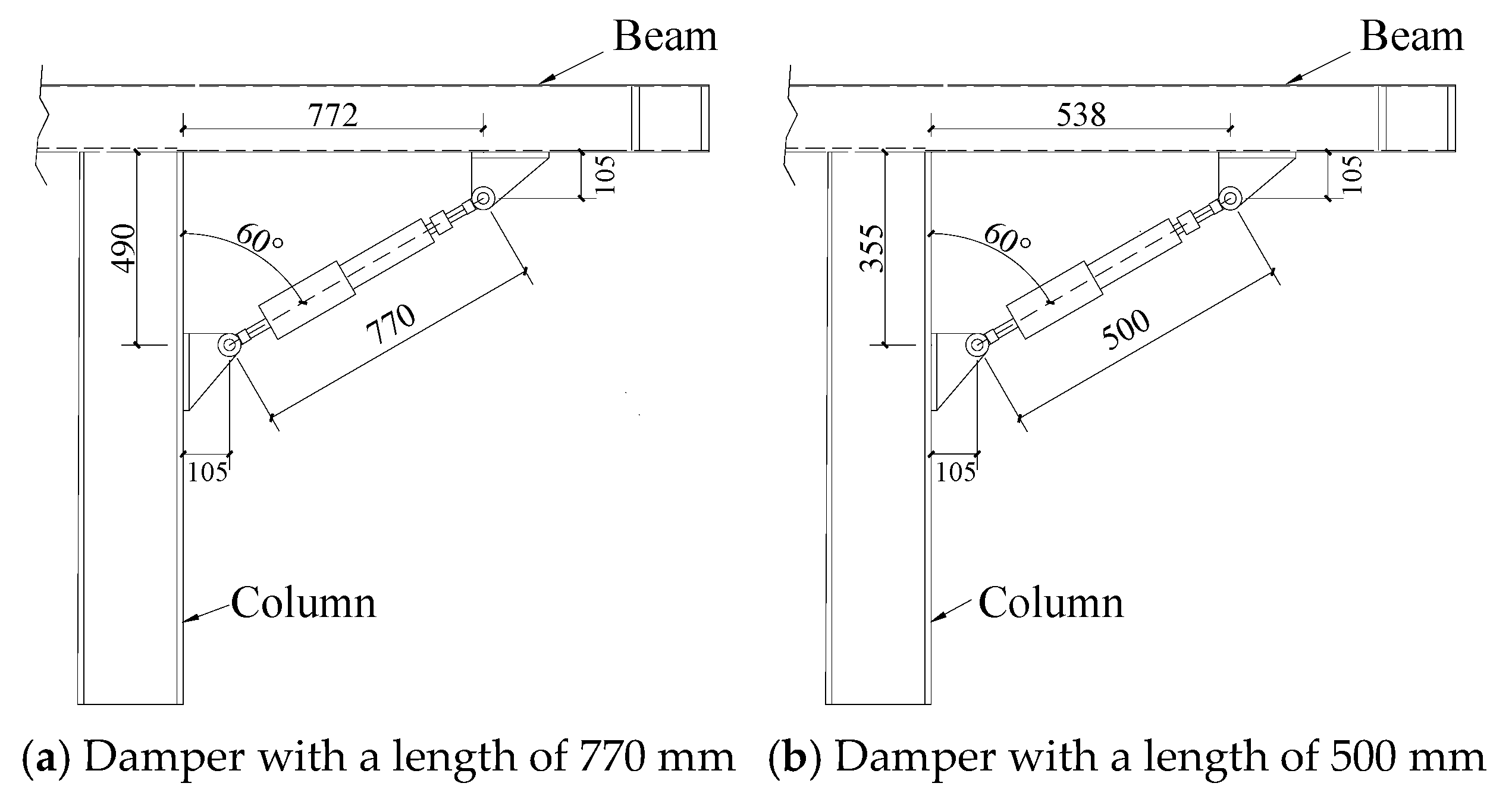
With the installation angle between the viscous damper and the column axis maintained at 60°, while the damper length was reduced from 770 mm to 500 mm. The corresponding installation configuration and geometric details are illustrated in
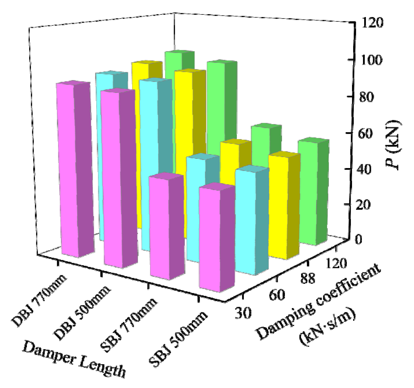
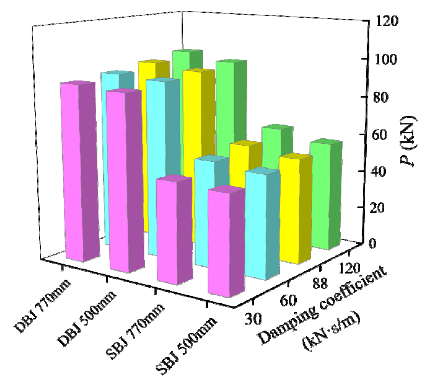
Figure 26. With all other parameters unchanged, comparisons of the peak loads of specimens with different damper lengths are presented in
Figure 27. The results show that shortening the damper length from 770 mm to 500 mm leads to a reduction in peak load for both the SBJ and DBJ series specimens. For the SBJ series, the peak load decreases by 1.81%, 4.33%, 5.58%, and 7.67% at damping coefficients of 30, 60, 88, and 120 kN·s·m
−1, respectively. For the DBJ series, the corresponding reductions are 1.54%, 1.51%, 2.69%, and 3.83%. Although a decrease in peak load is observed, the absolute reduction remains relatively small and generally does not exceed 4 kN. Under otherwise identical loading conditions, variations in damper length have a limited influence on the load-carrying capacity of the joints. These results indicate that a certain degree of flexibility in damper length selection can be accommodated in practical engineering applications. This allows spatial constraints to be satisfied without significantly compromising the joint load-bearing performance.
(2) Energy dissipation analysis of joints
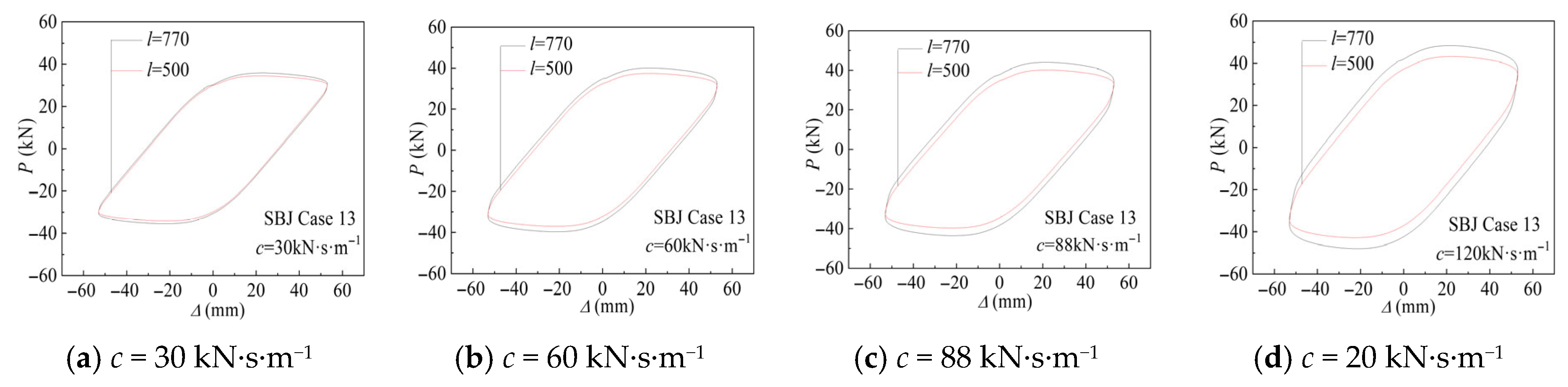
The third hysteretic loops obtained from the finite element analysis under loading cases 9, 11, and 13 were extracted for comparison, as shown in
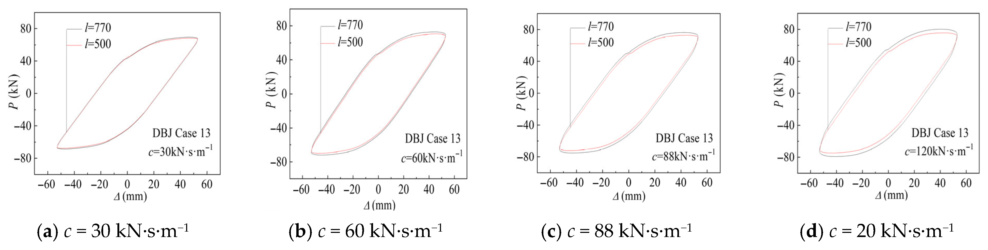
Figure 28 and
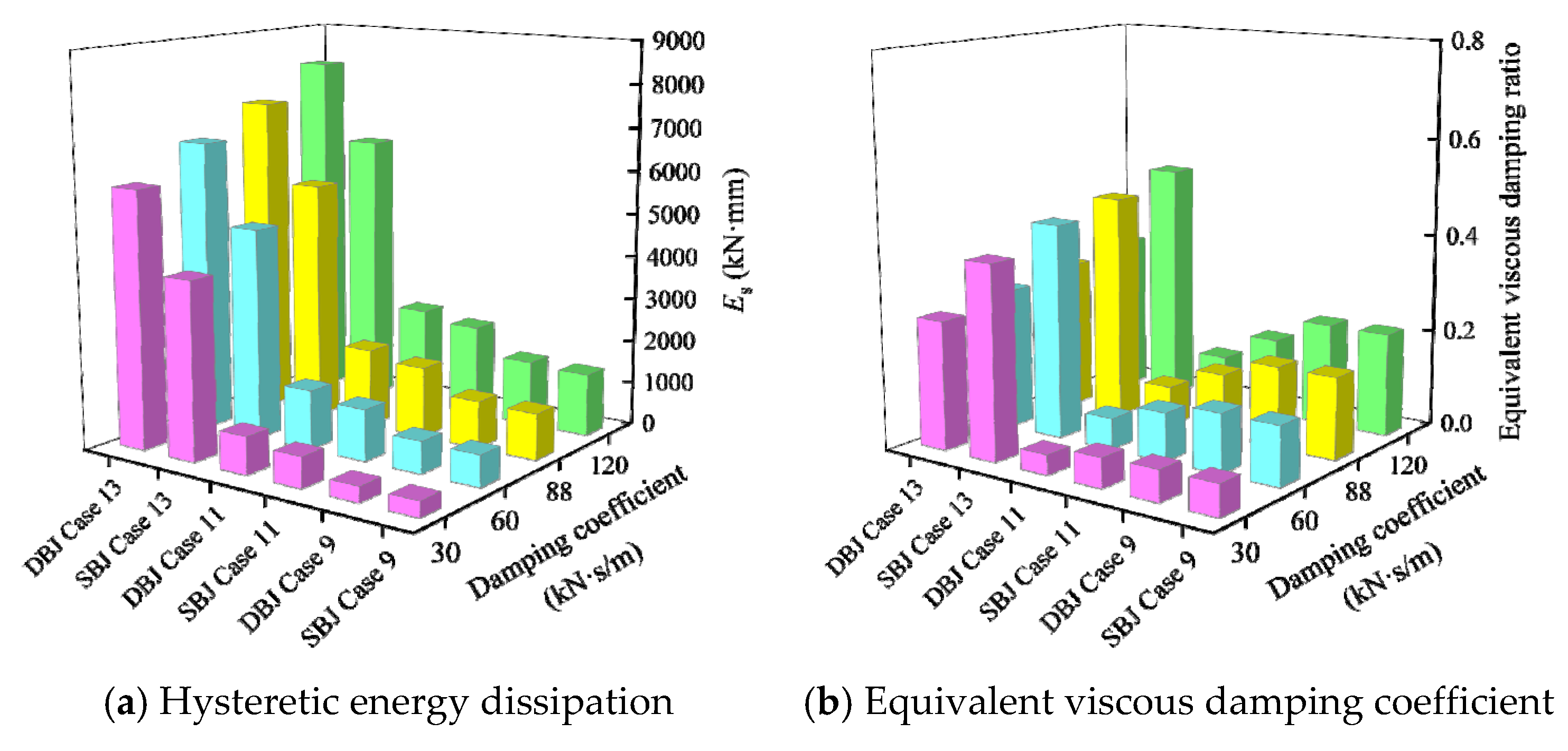
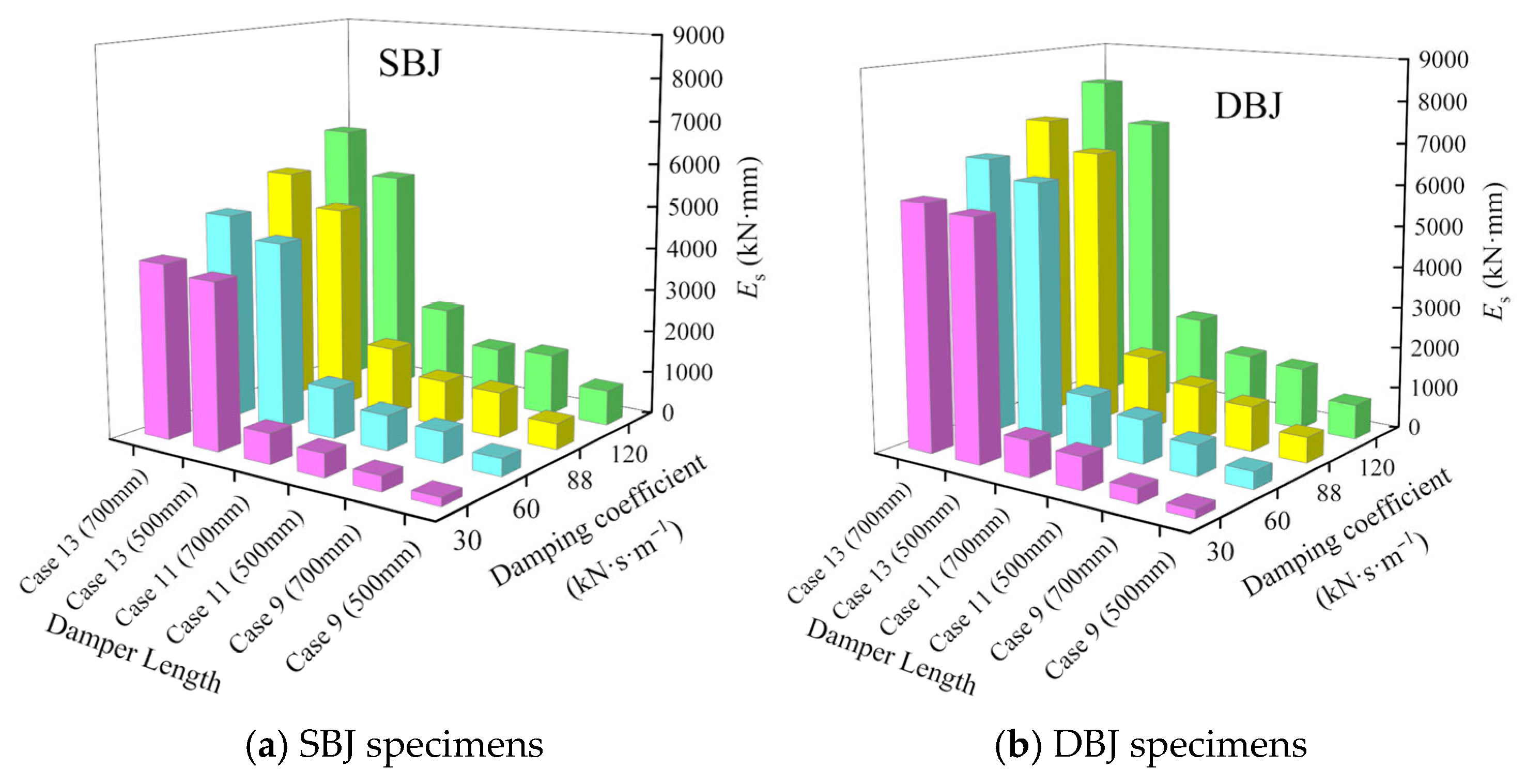
Figure 29. The corresponding hysteretic energy dissipation and equivalent viscous damping coefficients are presented in
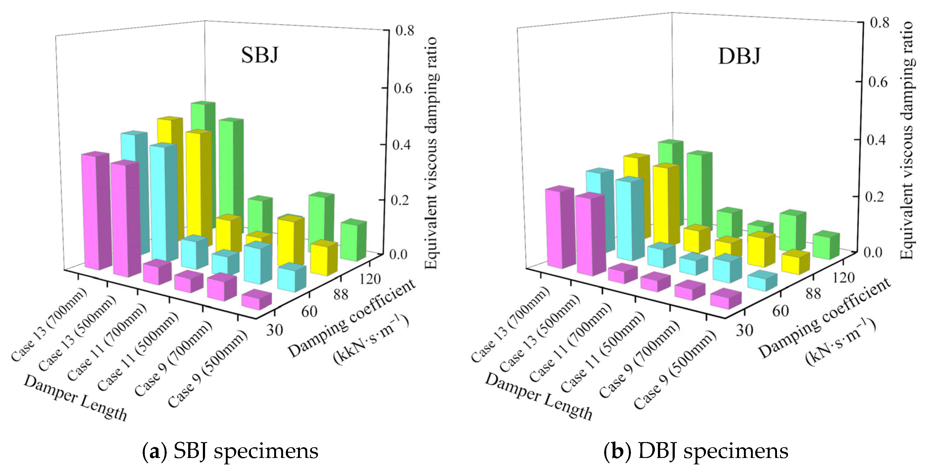
Figure 30 and
Figure 31, respectively. At relatively low damping coefficients, variations in damper length have a limited influence on the shape of the hysteretic loops, and the energy dissipation characteristics of the specimens remain largely comparable. When the damping coefficient increases to 120 kN·s·m
−1, specimens equipped with 770 mm-long dampers exhibit noticeably fuller hysteretic loops than those with 500 mm-long dampers. Correspondingly, both the hysteretic energy dissipation and the equivalent viscous damping coefficient of specimens with longer dampers are slightly higher under identical loading conditions. This behavior is attributed to the enhanced restraint provided by the longer dampers. The longer dampers promote greater deformation participation of the damping device and thereby improve the overall energy dissipation performance of the joint.
(3) Performance of viscous dampers
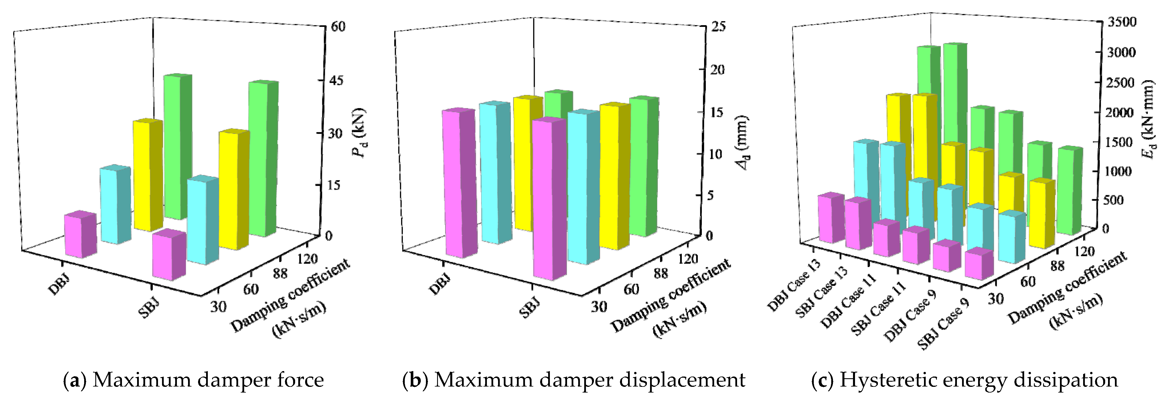
The maximum damper force, maximum displacement, and hysteretic energy dissipation under loading cases 9, 11, and 13 were extracted from the finite element analysis results. The corresponding results are presented in
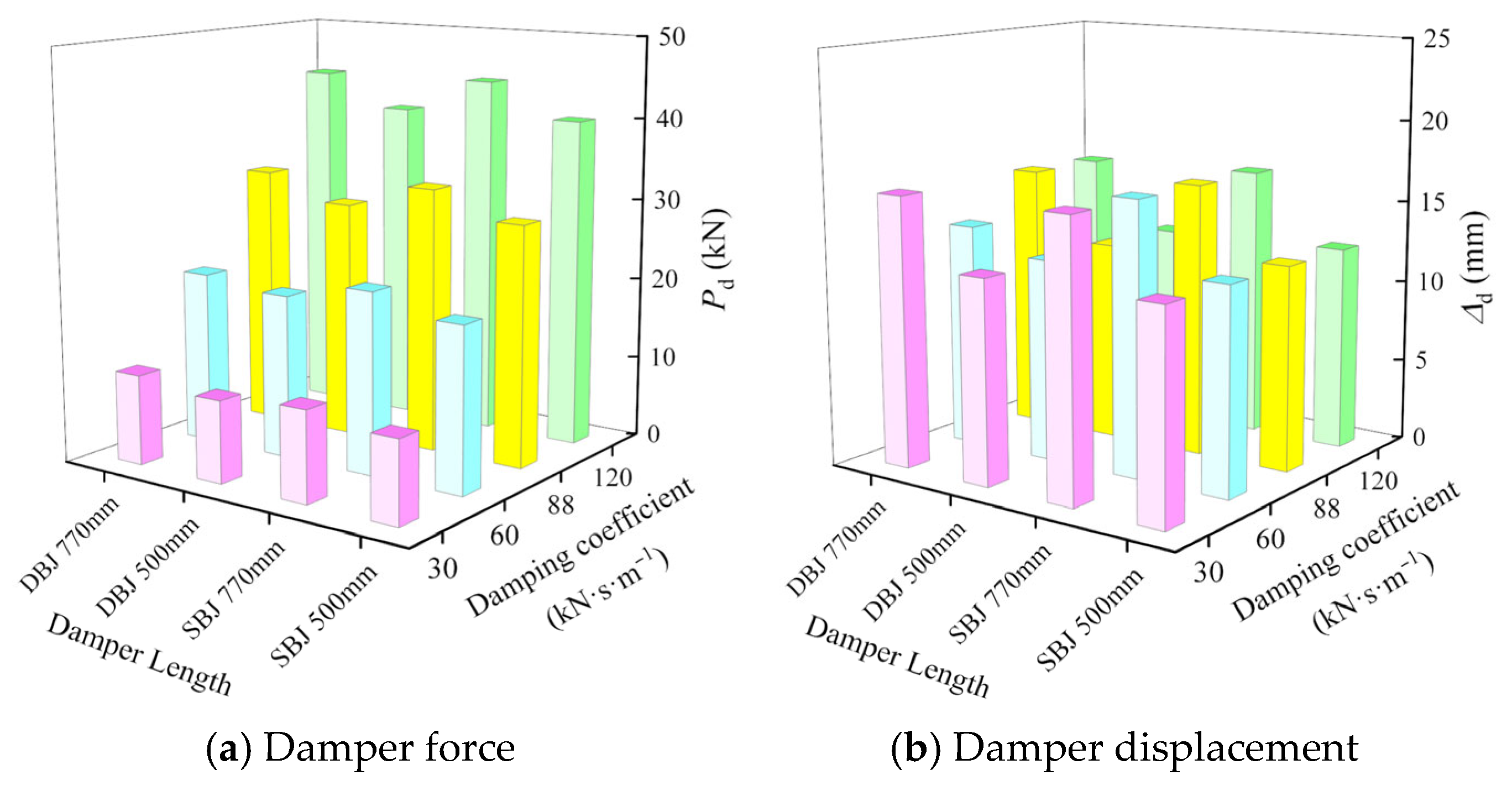
Figure 32 and
Figure 33. For damping coefficients of 30, 60, 88, and 120 kN·s·m
−1, the maximum displacement of the 770 mm-long damper was consistently about 4 mm larger than that of the 500 mm-long damper. This difference remained nearly constant as the damping coefficient increased. In contrast, the maximum damper force exhibited a pronounced increase with increasing damping coefficient. Under identical damping coefficients, the maximum force of the 770 mm-long damper was approximately 1, 2, 3, and 4 kN higher than that of the 500 mm-long damper, corresponding to an increase of about 10%. In terms of hysteretic energy dissipation, dampers with an installation length of 770 mm exhibited higher energy dissipation capacity under all loading cases. Under loading case 9, the hysteretic energy dissipation increased by approximately 150, 300, 450, and 600 kN·mm, respectively. Under loading case 11, the corresponding increases were about 200, 400, 600, and 800 kN·mm, while under loading case 13, the increases reached approximately 250, 500, 750, and 1000 kN·mm. Overall, both the maximum damper force and the hysteretic energy dissipation increased with the damping coefficient and followed an approximately linear trend. These results demonstrate that the maximum displacement of the viscous damper is primarily governed by its installation length and is only weakly influenced by the damping coefficient. In contrast, the damper force and energy dissipation capacity are mainly controlled by the damping coefficient.
Overall, since the resisting force of viscous dampers is governed by velocity-dependent behavior, the influence of damper length on joint performance remains relatively limited. The observed variations are mainly associated with changes in the effective force arm caused by different installation configurations. Increasing the installation length slightly enhances damper deformation participation and energy dissipation efficiency, whereas its influence on the damper force response is comparatively minor.
4.4. Design Recommendations
The proposed design methodology for irregular steel joints with viscous dampers in MCTBs should satisfy the seismic energy-dissipation requirements of viscous dampers and the geometric and aesthetic constraints of traditional architectural forms. Unlike conventional steel frame systems, the installation of dampers in MCTBs is significantly restricted by decorative structural components such as Que-Ti braces and beam–column architectural detailing. Therefore, the design is governed not only by mechanical performance requirements but also by spatial adaptability and architectural compatibility. Based on the experimental results and finite element analyses presented in this study, the key design variables of viscous dampers in irregular joints can be systematically classified into three categories: (i) geometric configuration parameters (damper dimensions and installation angle), (ii) performance control parameters (damping coefficient, stroke capacity, and peak force demand), and (iii) layout control parameters (installation position and number of dampers). These parameters jointly determine the force transfer mechanism and energy-dissipation contribution of the dampers within the joint system.
(1) Damper size design
The damper dimensions should satisfy both architectural spatial constraints and structural performance requirements. On one hand, the damper should not excessively occupy interior space or disrupt the visual continuity of traditional architectural elements. Therefore, its length should be coordinated with the geometric scale of Que-Ti components while maintaining sufficient clearance for architectural detailing. On the other hand, an excessively small damper size may result in an insufficient distance between the damper support and the beam-end plastic hinge region, which may induce premature stiffness concentration and adversely affect plastic hinge development. According to traditional architectural proportion rules and previous studies, the horizontal length of Que-Ti braces is typically within 1/4–1/3 of the bay span. Combining experimental observations and numerical results in this study, the horizontal length of the damper is recommended to be 2–3 times the depth of the beam section. This range provides a rational balance between constructability constraints and the adequate development of plastic hinges and energy dissipation at the beam ends.
(2) Damper cross-sectional dimensions
The damper cross-sectional dimensions should be compatible with the available installation space in traditional architectural configurations. Taking a second-grade traditional hall as an example, the eave column diameter is approximately 720 mm. Based on the typical proportion that the thickness of Que-Ti braces is about 3/10 of the column diameter, an effective installation space of approximately 216 mm can be provided. This space is generally sufficient for accommodating viscous dampers used in engineering applications. Therefore, under the condition of satisfying structural connections and installation requirements, the damper cross-section is considered to have good adaptability in MCTBs.
(3) Installation angle of dampers
The installation angle θ of the damper should be determined by considering both mechanical efficiency and architectural compatibility. Based on the experimental and numerical results, an installation angle of 60° provides a favorable balance between force transmission efficiency and structural compatibility. In addition, considering regional variations in traditional architectural forms, alternative installation angles such as 45° may also be adopted depending on the geometric proportions of Que-Ti components to better satisfy architectural aesthetics.
(4) Stroke, peak force, and peak velocity requirements
Based on previous studies and design practice, the maximum stroke of the damper should not be less than 1.3 times the maximum inter story displacement demand of the structure. Similarly, both the maximum velocity and maximum force capacity of the damper should also exceed 1.3 times the corresponding structural response demands to ensure sufficient safety margin. The proposed numerical framework provides an efficient tool for evaluating and verifying these performance requirements and can be extended to other types of structures equipped with supplemental viscous dampers.
The stroke capacity, maximum damping force, and maximum velocity are key control parameters in engineering design. These parameters can be effectively evaluated through the proposed finite element modeling in ABAQUS, which enables accurate prediction of damper velocity and displacement responses under different loading conditions.
It should be noted that the present study is at a conceptual design stage. The viscous dampers adopted in the experiments are commercially available products equipped with displacement and force sensors, which are relatively larger in size to ensure reliable data acquisition. Therefore, the current configuration is not optimized for architectural integration. In practical applications, more compact dampers specifically developed for architectural use can be expected in future research. In such cases, the damper can be installed within the beam–column joint region, and a steel cover plate with a Que-Ti-inspired external profile may be welded to the structural members to preserve the traditional architectural appearance while accommodating the energy dissipation device.
5. Conclusions and Future Research
5.1. Conclusions
Based on cyclic dynamic tests on six irregular steel joints equipped with viscous dampers in MCTBs, combined with parametric finite element results, the main conclusions are summarized as follows:
(1) The proposed displacement–frequency coupled sinusoidal loading protocol is capable of effectively reproducing the velocity-dependent cyclic behavior of viscous dampers and joint systems. Compared with conventional quasi-static loading methods, the adopted protocol enables a more realistic representation of seismic demand on velocity-sensitive damping devices. This provides a reliable experimental basis for evaluating the coupled force–velocity–displacement response of damper-equipped irregular joints.
(2) The installation of viscous dampers at the Que-Ti brace region significantly modifies the failure mechanism of irregular beam–column joints. Instead of early weld fracture and abrupt strength degradation observed in conventional joints, the damper-equipped specimens exhibit a transition toward a more distributed plasticity mechanism, in which energy dissipation is partially transferred from welded regions to replaceable damping devices. This mechanism effectively delays the localization of damage at beam-end plastic hinge regions and improves structural deformation stability. Moreover, double beam–column joints exhibit more efficient damper activation due to additional geometric restraint, leading to enhanced load-carrying and energy-dissipation capacity compared with single beam–column configurations.
(3) The developed finite element modeling strategy using Slot and Axial connector elements can accurately capture the load transfer mechanism between beams, columns, and viscous dampers. The good agreement between numerical and experimental results in terms of hysteretic response and peak resistance indicates that the model is suitable not only for response prediction but also for parametric investigation and design-oriented evaluation of damper-equipped irregular joints in MCTBs.
(4) The damping coefficient is the dominant factor influencing both global energy dissipation capacity and peak damper force, exhibiting an approximately linear enhancement trend within the studied range. In contrast, the column axial compression ratio has a secondary influence, indicating that the system response is primarily governed by deformation compatibility rather than axial force level. The damper length mainly affects deformation demand and displacement capacity, while its influence on global load-carrying capacity is limited. In general, the maximum damper displacement is controlled by geometric constraints, whereas force and energy dissipation are primarily governed by damping properties.
(5) The damper-equipped joints exhibit stable hysteretic behavior, confirming the effectiveness of viscous dampers in improving seismic performance. The system provides a reliable energy-dissipation mechanism in which seismic energy is mainly dissipated by dampers rather than welded connections.
5.2. Future Research
(1) Fatigue behavior of viscous dampers under small-amplitude cyclic loading.
Although the present study focuses on relatively large deformation demands, the fatigue performance and degradation of viscous dampers under repeated small-amplitude loading require further investigation for practical applications.
(2) Refined damper design for architectural integration in MCTBs.
Future work should develop compact dampers suitable for integration within Que-Ti architectural components, balancing mechanical performance and architectural requirements.
(3) Full-scale structural validation and system-level seismic performance.
The proposed system should be validated through shaking table tests or full-scale numerical simulations to assess global seismic response and system redundancy.
(4) Long-term durability and environmental effects.
The effects of temperature variation, aging, and environmental degradation on damper performance stability should be further studied.