Article

Experimental and Numerical Investigations of Flexural Strengthening of Reinforced Concrete Beams Using Textile Glass Fabric


1
Department of Civil and Infrastructure Engineering, Al-Zaytoonah University of Jordan, P.O. Box 130, Amman 11733, Jordan
2
Department of Engineering Project Management, Jadara University, P.O. Box 733, Irbid 21110, Jordan
3
Department of Civil Engineering, University of Mississippi, P.O. Box 1848, Oxford, MS 38677, USA
4
Department of Civil Engineering, University of Jordan, Amman 11942, Jordan
5
Civil Engineering Program, Al Ain University, Al Ain P.O. Box 64141, United Arab Emirates
6
Al Ain University Center for Water, Energy, and Sustainability, Al Ain University, Al Ain P.O. Box 64141, United Arab Emirates
7
Department of Civil Engineering, Al Al-Bayt University, P.O. Box 130040, Almafraq 25113, Jordan
*
Author to whom correspondence should be addressed.
Buildings 2026, 16(10), 1907; https://doi.org/10.3390/buildings16101907
Submission received: 2 March 2026 / Revised: 8 April 2026 / Accepted: 6 May 2026 / Published: 11 May 2026
(This article belongs to the Section Building Structures)

Abstract

Textile-reinforced concrete (TRC) beams have attracted widespread interest in recent years as an alternative to fiber-reinforced polymer (FRP) techniques. However, despite their effectiveness, they are often associated with high material cost, sensitivity to elevated temperatures, and limitations in bonding performance under certain environmental and surface conditions. This research examines incorporating textile reinforcement internally (INT) by supplementing steel bars with glass fiber grids, as well as externally (EXT) by retrofitting existing members. The experimental work evaluates five RC beams: a control (CTR), two INT beams strengthened with alkali-resistant glass fabric textile (AR-GFT), one using one layer (INT1L) and the other three layers (INT3L), and two EXT beams where AR-GFT is bonded with mortar, again with one layer (EXT1L) and three layers (EXT3L). Altogether, 10 beams were tested, with duplicate specimens for every configuration. Observing load-deflection responses, cracking behavior, and the strengthening system’s performance revealed that AR-GFT contributes to enhanced load-bearing resistance in the RC beams. The INT1L beams exhibited negligible improvement compared with the CTR specimen, suggesting that internal strengthening alone does not meaningfully increase strength. Conversely, the INT3L beams demonstrated a 45% rise in strength for one sample, although the second performed similarly to the CTR specimen owing to slippage between the textile and adjacent matrix. EXT3L beams achieved up to a 90% increase in load-bearing capacity in one specimen. Nevertheless, the second specimen exhibited textile layer debonding and performed similarly to the CTR beam, underlining the necessity for correct textile positioning and sufficient mortar impregnation during application. Moreover, a three-dimensional (3D) nonlinear finite-element analysis (FEA) was performed to replicate beam responses, showing strong correlation with experimental observations. Overall, the results indicate that textile-based strengthening systems can successfully retrofit and upgrade RC structures, provided meticulous attention is paid to the quality and execution of the installation process. The study provides new insights into the flexural behavior of textile-strengthened RC beams, particularly in terms of the interaction between internal and external textile reinforcement with conventional steel.

1. Introduction

Over the past several decades, the repair and strengthening of reinforced concrete (RC) structures have become increasingly important due to deterioration, aging, and environmental degradation. A number of retrofit and reinforcement techniques for existing concrete members have been developed and evaluated [1,2,3,4,5,6,7].

Fiber-Reinforced Polymer (FRP)

FRP fabrics are widely used in structural rehabilitation due to their minimal thermal conductivity, low self-weight, excellent strength-to-weight characteristics, reliable performance, ease and rapidity of application, and durability under aggressive environmental conditions [8]. Extensive research has examined the role of FRP in confining thermally damaged concrete columns [9,10,11] and in restoring chemically deteriorated columns [12,13,14]. The confinement provided by FRP has proven to be effective, enhancing both load-bearing capacity and ductility of structural elements. Recent work by Jafari et al. [15] investigated the flexural performance of continuous RC beams strengthened by using hybrid CFRP–GFRP sheets through experimental testing and analytical modeling, demonstrating the effectiveness of combining different fiber types to enhance strength and modify failure mechanisms, thereby providing further insight into the behavior of composite-based strengthening systems. Nonetheless, FRP-based methods present several drawbacks, including poor resistance to higher temperatures, challenges when installing on damp substrates, high costs associated with materials and skilled labor, and suboptimal bonding between the binder and the concrete surface.
Recent reviews of FRP flag several areas where the science is maturing. Ma [16] provides a systematic overview, noting that bond behavior between FRP bars and concrete is now fairly well characterized through pullout tests, though gaps remain regarding the performance of long-term bond durability and dynamic fatigue performance. A key design challenge is that FRP bars have a lower elastic modulus than steel, which results in wider cracks and larger deflections for equivalent reinforcement ratios. Duarte et al. [17] showed experimentally that adding polypropylene macro fibers to concrete can partly compensate: complete replacement of GFRP stirrups with macro fibers improved shear resistance by approximately 78% for GFRP-reinforced beams and 60% for BFRP beams, and in beams with insufficient stirrups, adding fibers shifted the failure mode from brittle shear to pseudo-ductile flexural failure. Bywalski et al. [18] introduced GFRP-headed bars as an alternative to conventional GFRP stirrups. These allow stress redistribution across diagonal cracks, addressing a fundamental limitation of linear-elastic FRP reinforcement in shear.
Hammad et al. [19] covered externally bonded (EB) laminates, near-surface-mounted (NSM) bars, surface curvilinearization, and external prestressing with FRP, concluding that the full potential of these techniques has not yet been realized and that design methods require updating. For seismic applications specifically, Kabashi et al. [20] reported that FRP retrofitting of beam–column joints yields roughly a 25% increase in peak shear force and a 20% improvement in displacement capacity, based on a nonlinear finite-element analysis validated against experimental data.
Ye et al. [21] developed FRP grid-reinforced UHPC composite plates and reported that including an FRP grid enhanced ultimate flexural capacity by over 150% and ultimate tensile capacity by over 200%, with the composite exhibiting tensile strain-hardening behavior. They added that the interaction between the FRP grid and UHPC is also notable: steel fibers in the UHPC pass through the grid openings, reducing the likelihood of FRP debonding. Yan et al. [22] showed that GFRP bars reduced maximum displacements under close-in blast loading, enhancing blast performance of UHPC beams, though with larger rebound displacements. Zeng et al. [23] investigated different fiber types (steel, basalt, PE) in FRP grid-UHPC plates and found up to 200% enhancement in flexural capacity with PE fiber additions. Tao et al. [24] compared GFRP-UHPC and GFRP-normal concrete hybrid beams in shear and found that the UHPC version had higher load-bearing capacity, stiffness, and notably greater ductility upon compressive damage.
Li et al. [25] highlight several emerging innovations: nanotechnology-enhanced adhesives to mitigate the persistent debonding problem, machine learning models for predictive structural analysis, and sustainable bio-based FRPs derived from renewable resources. A separate review by Zhang [26] notes that MXene, a two-dimensional nanomaterial, is being incorporated into FRP composites to enhance mechanical strength, environmental stability, and electrical/thermal properties.
Real-world durability data is accumulating. Gooranorimi et al. [27] extracted GFRP bars from two Missouri bridges after 10–15 years of service and found no microstructural degradation via SEM/EDS, with horizontal shear strength and glass transition temperature slightly improved relative to pristine samples. Laboratory accelerated aging tells a more nuanced story: Fergani [28] tested 348 GFRP specimens across multiple environments and temperatures and found that while the elastic modulus was largely unaffected, tensile and flexural strength degraded, driven primarily by chemical reactions accelerated at elevated temperatures. Stressed specimens in wet conditions showed reduced tension stiffening and bond degradation. Gajdošová et al. [29] argue that current code-specified environmental reduction factors (as low as 0.5 for GFRP) are overly conservative relative to actual field performance.
Across the reviews, the same gaps recur: fire resistance remains poorly understood (FRP properties degrade significantly at elevated temperatures), long-term performance under sustained stress in complex environments needs better prediction models, and design codes still lag behind experimental findings [16,19,25]. The economic case is mixed: FRP materials cost more upfront than steel, but lifecycle cost analyses increasingly favor FRP in corrosive environments such as marine structures, bridges, and tunnels [30].
Textile-reinforced concrete (TRC) is increasingly gaining traction in civil engineering as a viable alternative to FRP, addressing many of its limitations. Replacing continuous fiber sheets with textile meshes can improve bond performance within cementitious composites [31,32,33,34]. Textiles consist of fiber threads interlaced or stitched in two orthogonal directions to form an open-mesh grid. Typically, they are manufactured from high-strength fibers such as alkali-resistant (AR) glass, carbon, or basalt, which are embedded in a fine-grained, high-performance mortar matrix [32,35]. Studies have shown that fabric geometries with suitable configurations can significantly enhance the mechanical behavior of cement-based composites compared with straight non-fiber yarns [36,37,38,39,40]. These textile-based composites were originally referred to as TRC or textile-reinforced mortar (TRM) in Europe; however, due to the extremely fine aggregate sizes, the inorganic matrix does not strictly qualify as concrete. In the US, the material is commonly referred to as a fabric-reinforced cementitious matrix, although this designation is somewhat misleading since the matrix may not always be cement-based (e.g., hydraulic lime) [41].
Multiple experimental investigations have been conducted to contrast the effectiveness of FRP and textile systems applied externally for flexural and shear strengthening of RC beams. Raoof et al. [42] examined the two-point bending response of RC beams retrofitted using TRM and FRP. Their parameters included the number of reinforcement layers, textile surface condition (coated vs. uncoated), fiber type in the textile (coated basalt, carbon, or glass fibers) with comparable axial stiffness, and the anchorage system used at the ends of the external reinforcement. Results indicated that TRM produced a slightly lower enhancement in load-bearing capacity compared with FRP-strengthened beams. Nonetheless, the efficiency of TRM was highly dependent on the number of textile layers incorporated. The failure mechanisms observed in textile-strengthened RC beams depend on parameters such as surface treatment, fiber type, and number of TRM layers, while U-shaped jacketing produces only a small improvement in TRM-strengthened beams under flexure but significantly affects FRP-strengthened beams. Elsanadedy et al. [43] found that a basalt fiber TRM system enhanced flexural strength by only 7.2%, yet increased ductility by 61% compared with a basalt FRP system, when comparing a beam strengthened with five TRM layers in a U-wrap to one strengthened with a single FRP layer. Using LS-DYNA, they simulated the beams and interfacial behavior, concluding that TRM strengthening led to flexural failure via textile rupture or end debonding. Tetta et al. [44] similarly compared TRM and FRP for shear upgrades and observed that TRM was less effective in increasing shear capacity but enhanced deformation ability more than FRP, with the number of layers and wrapping configuration affecting both systems. Triantafillou and Papnicolaou [31], based on two test beams, also reported that TRM was around 30% less efficient than FRP, with FRP-fortified beams failing by fiber rupture and TRM-fortified beams by interlaminar debonding.
Additional research has examined the incorporation of glass fabric textiles (GFT) as internal reinforcement in RC beams and slabs. Findings revealed that utilizing a unidirectional glass fiber grid as transverse reinforcement effectively enhanced shear resistance, postponed the onset of cracking, and reduced crack width in polypropylene fiber-reinforced foamed concrete beams subjected to four-point bending [45]. Similarly, applying a bidirectional glass grid increased the flexural strength of scaled foamed concrete beams tested under a three-point loading configuration [46]. The integration of glass fiber grids (GFG) and polypropylene meshes into slab systems was shown to improve punching shear capacity, promote a favorable crack distribution, and allow larger deflections prior to failure in comparison with unreinforced slabs [47]. Moreover, bond-slip assessments indicated that GFG provided superior interfacial behavior between the reinforcement and concrete than externally bonded FRP surface plates. Allouzi [48] further explored these findings through combined experimental and numerical evaluations of six simply supported foamed concrete slabs subjected to three-point bending. Various reinforcement configurations were evaluated, comprising two slabs reinforced with GFG placed at the tension face, two with traditional steel bars at the tension face, and two containing steel-in-tension coupled with GFG positioned in the compression region. Glass fiber grids (GFG) were not expected to resist compressive stresses effectively and therefore was not intended to bear compressive loads; instead, it was located at the compression face to mitigate sudden widening of cracks by bridging the two crack flanks as flexural cracks rapidly progressed towards the top surface of the porous foamed concrete. Test observations indicated that slabs reinforced solely with steel in tension developed evenly distributed flexural cracks without reinforcement splitting and achieved the greatest flexural strength among the configurations tested. Slabs containing only GFG in tension did not possess sufficient bending capacity for typical residential applications. Specimens featuring GFG in compression alongside steel in tension demonstrated reduced flexural strength relative to slabs reinforced exclusively with steel in tension. Additionally, finite element simulations using Abaqus® captured load–deflection trends and crack evolution that closely matched experimental outcomes for all slab types [49]. Abd and Ghalib [50] investigated the flexural response of foamed concrete beams reinforced with glass-fiber-reinforced polymer (GFRP) bars by testing two foamed concrete beams and two conventional concrete beams, one of each reinforced with GFRP and the other with steel. Foamed concrete beams with GFRP reinforcement showed greater deflections and wider cracks compared with steel-reinforced beams, due to the comparatively lower modulus of elasticity of the GFRP bars.
Numerous investigations have analyzed the effectiveness of TRC for flexural retrofitting of RC beams, focusing on key variables such as fabric type including carbon fiber textiles [31,51,52], polyparaphenylene benzobisoxazole textiles [51,52,53,54], and basalt fiber textiles [43] the number of textile layers [42,43,51,52,53,54,55]; details of the strengthening layout [51]; and the concrete compressive strength [55]. Collectively, these studies demonstrated that textile-based strengthening enhances the flexural performance of RC beams and that increasing the number of textile layers not only further improves strength but may also alter the failure mechanism.
From a scientific perspective, there remains a limited understanding of the fundamental mechanisms governing the flexural behavior of textile-strengthened RC beams, particularly the interaction between textile reinforcement and steel, and the role of bond–interface behavior in stress transfer and failure development. From an applied perspective, there is a growing need for reliable, durable, and cost-effective alternatives to conventional FRP strengthening systems, which are often associated with high cost and practical limitations in field applications.
Previous research reflects a growing interest in upgrading RC structural members using advanced composite retrofitting techniques. While numerous studies have focused on externally applied textile systems, limited attention has been given to the comparative effectiveness of internal (embedded) versus external strengthening approaches within the same structural framework. Furthermore, the interaction between textile reinforcement and conventional steel reinforcement, as well as the influence of bond behavior and installation quality on structural performance, remains insufficiently understood. In addition to laboratory testing, three-dimensional (3D) nonlinear finite element models were constructed in Abaqus® to simulate the tested specimens, and the numerical outcomes were evaluated against the experimental results for validation [49].
Therefore, the main objective of this study is to investigate the flexural behavior of RC beams strengthened with alkali-resistant glass fiber textile through both experimental testing and numerical modeling. The specific objectives are to (i) evaluate and compare the effectiveness of internal and external strengthening configurations, (ii) examine the influence of the number of textile layers on structural performance and failure modes, and (iii) develop and validate a finite element model capable of simulating the observed behavior.

2. Experimental Program

2.1. Test Specimens

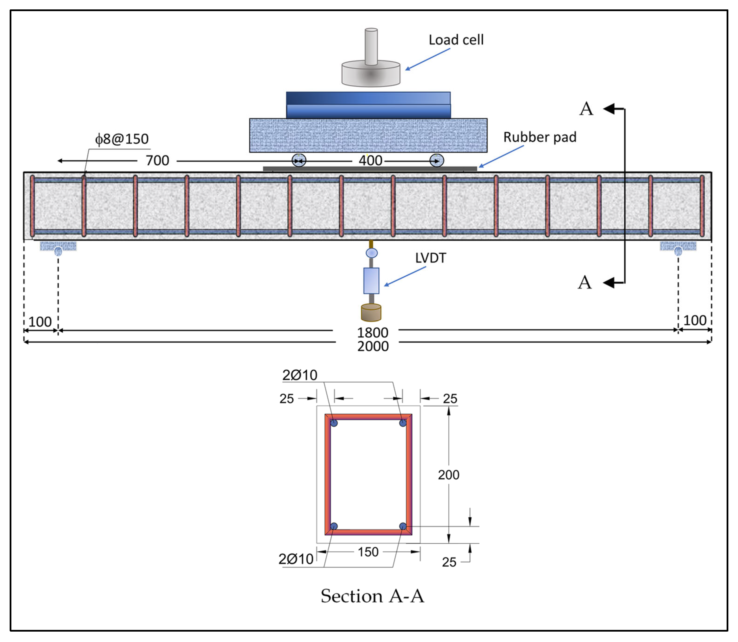
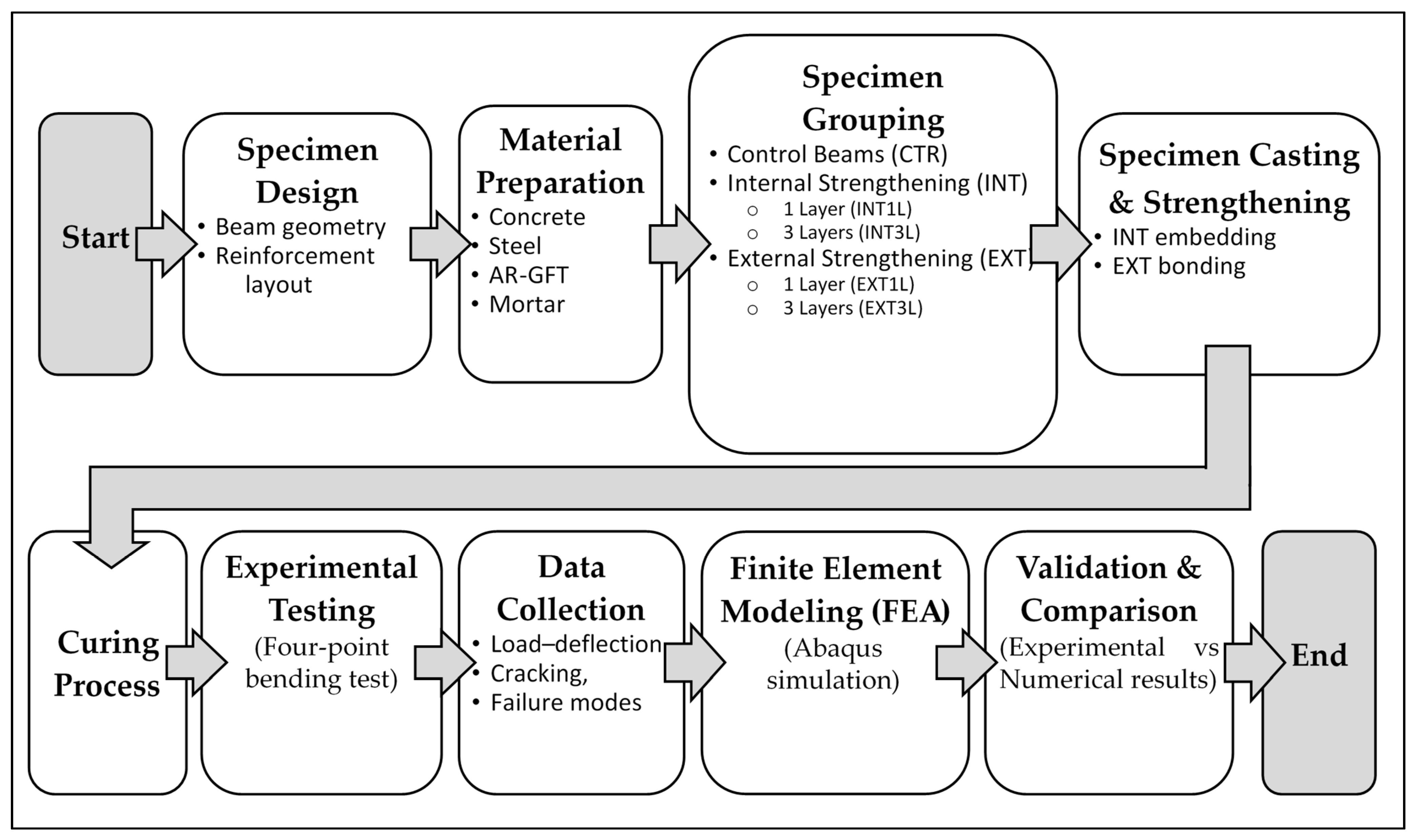
A comprehensive experimental program was carried out on ten full-scale simply supported RC beams, each measuring 150 × 200 × 2000 mm, and tested under a four-point loading configuration. Longitudinal reinforcement consisted of 2ϕ10 rebars placed at both the compression and tension faces with a concrete cover of 25 mm to the centerline of the bars, while shear reinforcement was provided through ϕ8- stirrups spaced at 150 mm centers. The beam dimensions and reinforcement layout were selected to represent typical under-reinforced RC beams commonly used in practice, ensuring that flexural behavior governs the response and that failure occurs through yielding of the tensile steel rather than premature shear or compression failure. The longitudinal reinforcement ratio (0.6%) was deliberately chosen to remain within the under-reinforced range, allowing for a clear assessment of the contribution of the textile strengthening system to the overall flexural capacity. The experimental program consisted of ten reinforced concrete beams, including two control specimens and eight strengthened specimens with different configurations, as summarized in Table 1. The overall experimental program adopted in this study is illustrated in Figure 1, which presents a flowchart summarizing the sequence of specimen preparation, strengthening procedures, testing, and numerical analysis.
Two identical control (CTR) beams were produced, with their reinforcement arrangement shown in Figure 2. To assess the influence of GFT on flexural performance, four internally strengthened specimens were cast, two incorporating a single textile layer (INT1L) and two containing three layers (INT3L); additionally, four externally strengthened specimens were prepared, comprising two beams with one fabric layer (EXT1L) and two beams with three layers (EXT3L). The selected strengthening configurations were designed to simulate realistic strengthening scenarios encountered in practice. The use of one and three textile layers was intended to investigate the influence of reinforcement quantity on structural performance, as increasing the number of layers is a common method for enhancing load-carrying capacity in strengthening applications. Additionally, the comparison between internal (embedded) and external strengthening techniques was adopted to evaluate the effectiveness of different retrofit strategies and to better understand the interaction between textile reinforcement and conventional steel reinforcement.

2.2. Materials

All beams were cast using the same batch of ready-mixed concrete. To determine the material properties, three 150 × 150 × 150 mm cubes were tested in compression, returning an average compressive strength of 50 MPa. For the reinforcing steel, the measured yield strengths were 517 MPa for the ϕ10 mm longitudinal bars and 280 MPa for the ϕ8 mm stirrups.
Glass fabric textile (GFT) was selected for beam strengthening due to its corrosion resistance, high strength-to-weight ratio, superior mechanical properties, flexibility, thermal and chemical stability, and ease of installation. It is manufactured by weaving high-grade fiberglass yarns and treating them to ensure AR. In this investigation, a unidirectional GFT with a 4 mm mesh opening was employed for both internal and external strengthening applications. The mechanical characteristics of the GFT are listed in Table 2. Figure 3 illustrates the AR-GFT used in this study, showing its warp and weft yarn orientations.
The mechanical properties presented in Table 2 were obtained from the manufacturer’s technical data sheet. It should be noted that these values represent the effective properties of the textile mesh system, which account for the influence of fiber arrangement, yarn waviness, and interaction between fibers within the grid, rather than the intrinsic properties of individual glass filaments.
The GFT external application used a gray powdered adhesive (255 StarFlex LD) featuring low dust generation. This adhesive consisted of high-grade cements, elevated polymer levels, chosen silica/quartz mineral fillers, and special admixtures. When mixed with water, the mortar exhibited a fresh density of 1.6 kg/L, an initial tensile bond capacity of 2.1 N/mm2, and could be layered to a maximum thickness of 15 mm. The adhesive mortar was prepared using a controlled mixing procedure from the manufacturer’s specifications, where 0.483 L of water was added per kilogram of dry material and mixed mechanically until a homogeneous consistency was achieved. The mixture was allowed to rest for 5–10 min before re-mixing prior to application.

2.3. Strengthening Methodology

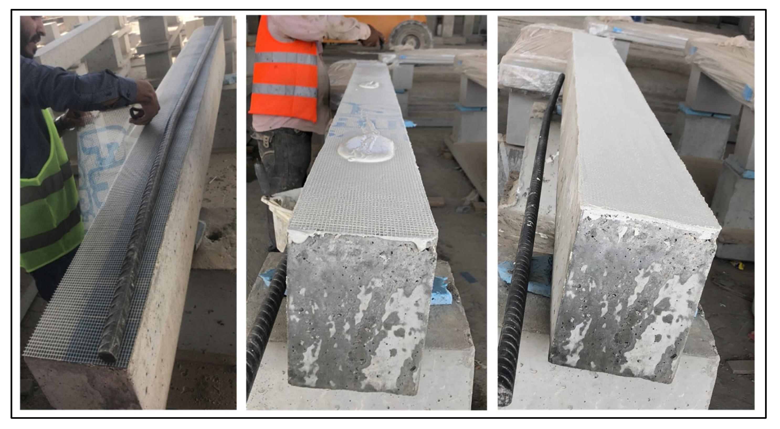
In the two EXT1L beams, a first 3 mm-thick mortar coating was trowelled across the underside of the beam; the GFT sheet was then slowly pressed onto the fresh layer, ensuring alignment by smoothing over the fiberglass. A second coat, 2–3 mm thick, was spread on top of the GFT layer. Conversely, for the two EXT3L beams, four coats of mortar, each 1.5 mm thick, were applied, with the GFT inserted between every two mortar layers. Consequently, the combined thickness of mortar and fabric amounted to 6–7 mm. Figure 4 shows the sequential steps for installing EXTL.
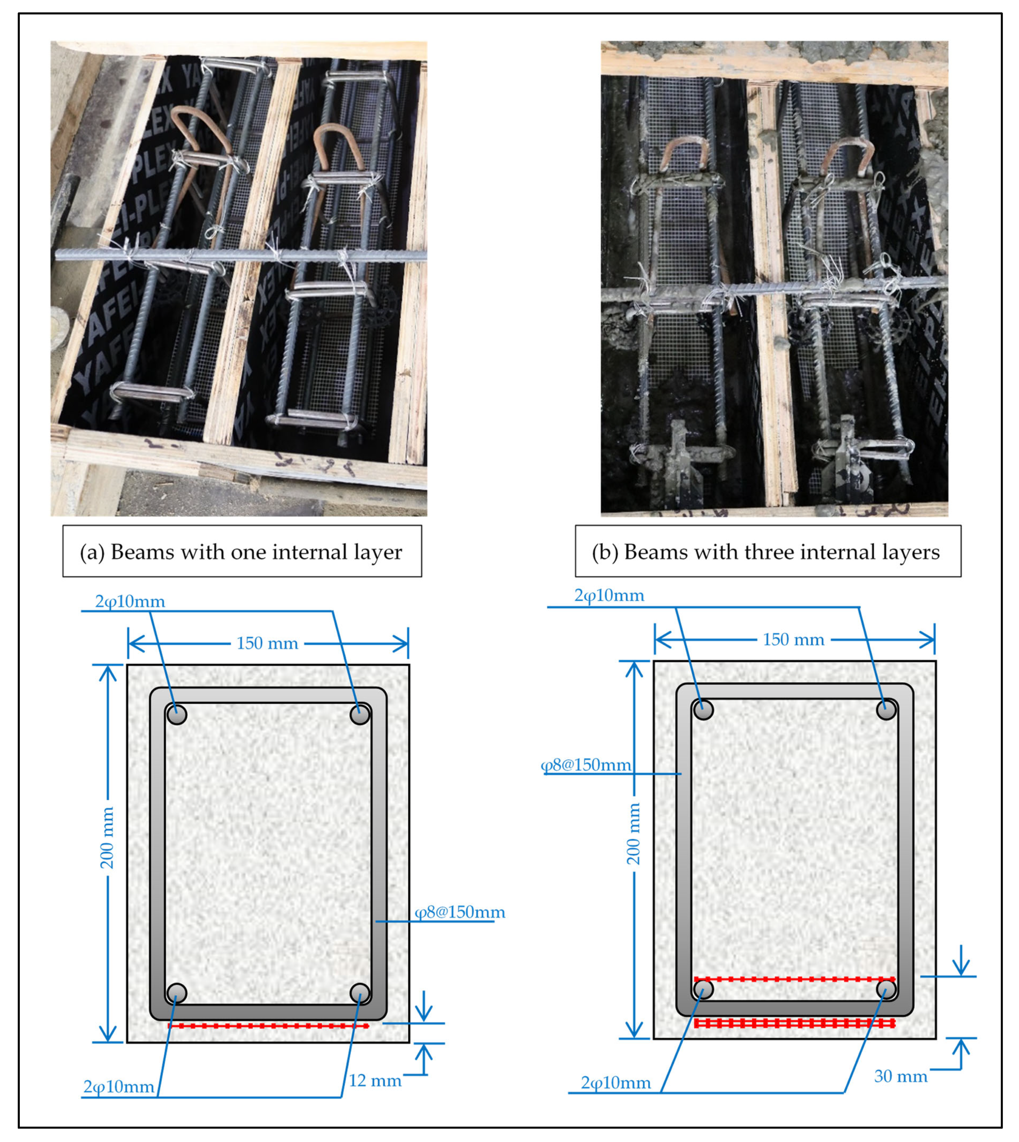
In the INT1L group, a single textile layer was positioned directly beneath the stirrups (Figure 5a). In contrast, the INT3L pair had two textile layers placed one atop the other below the stirrups initially (Figure 5b). Subsequently, a 3 cm-thick concrete layer was cast, and a third textile layer was fixed over the fresh concrete, located immediately above the main bottom reinforcing bars (Figure 5b). The space maintained between the two lower layers and the upper layer measured 1.8 cm. Figure 5 demonstrates the installation procedure for the INT setup.

2.4. Testing Set-Up

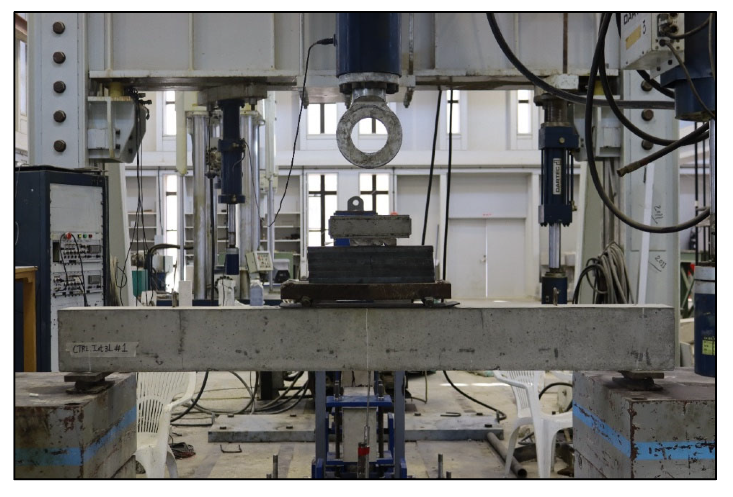
Each beam specimen was simply supported at both ends. The support center lines were located 100 mm in from each beam edge, giving a span of 1800 mm between centers. The supports rested on firm concrete blocks at the extremities. Loading was applied progressively using a high-capacity load cell, and deflection readings were taken at every 5 kN increment. A linear variable differential transformer positioned under the beam’s midpoint captured the vertical displacements. Figure 6 presents the experimental arrangement of the beams, and Figure 2 provides a schematic view of the test setup.

3. Experimental Results and Discussion

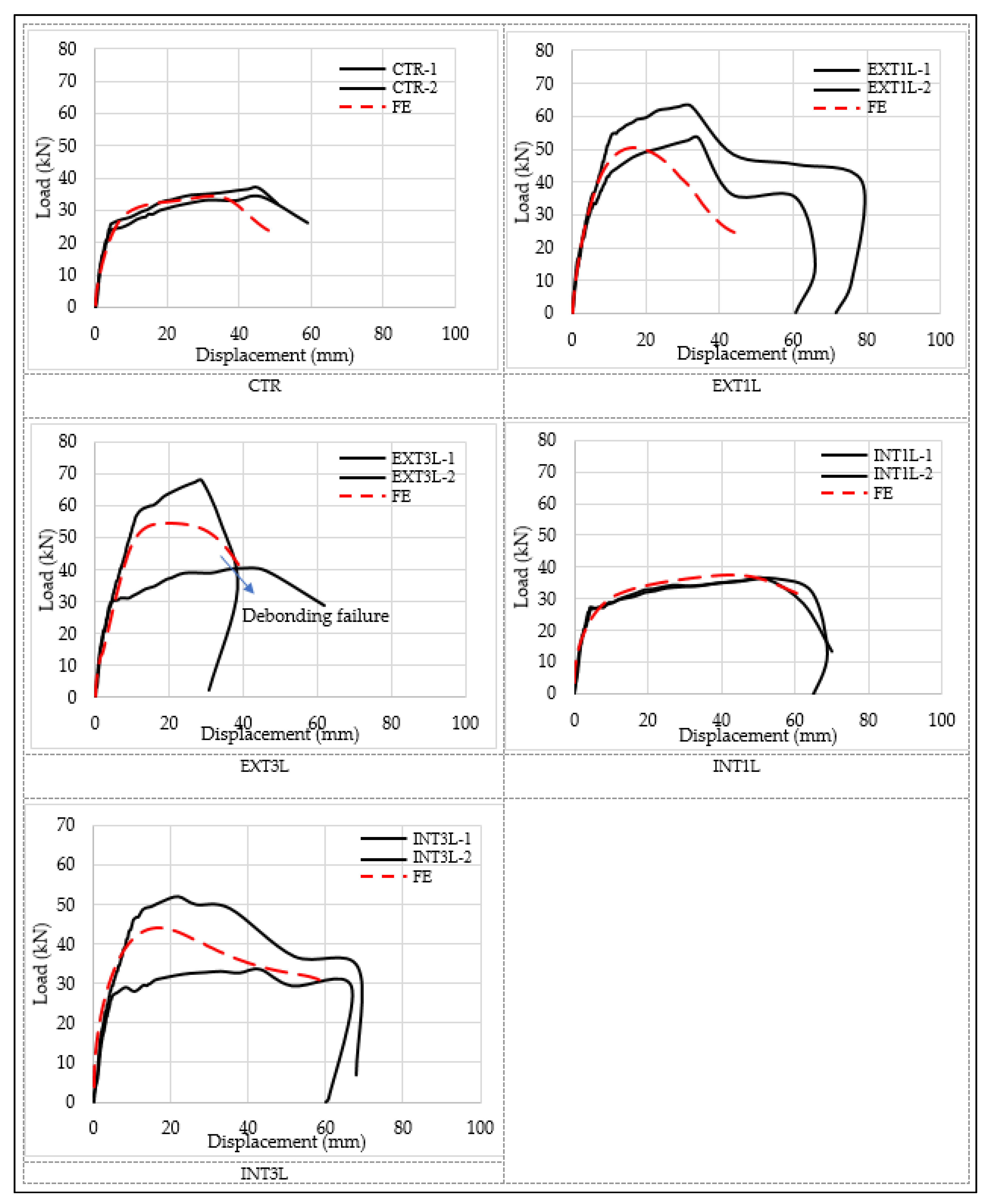
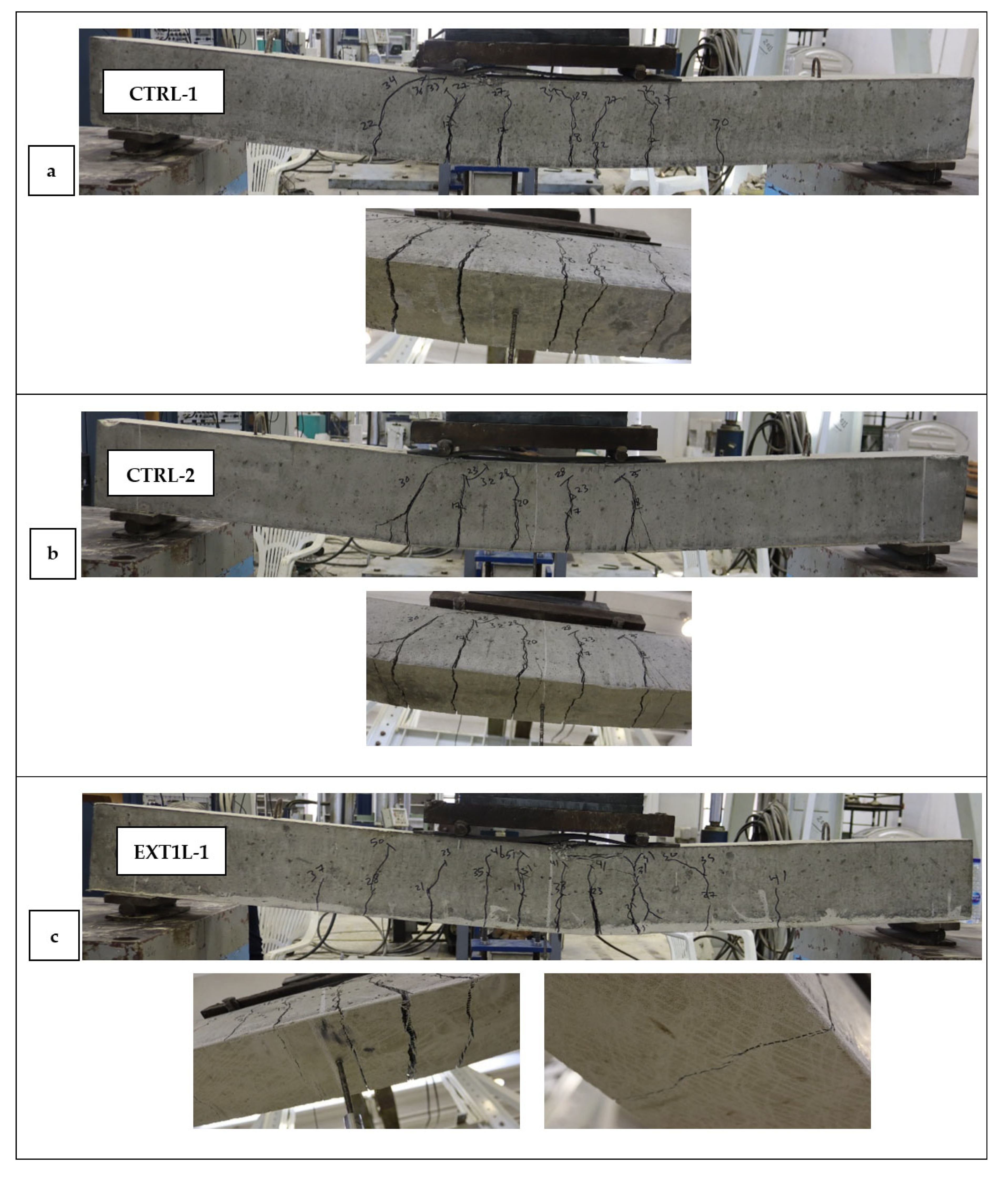
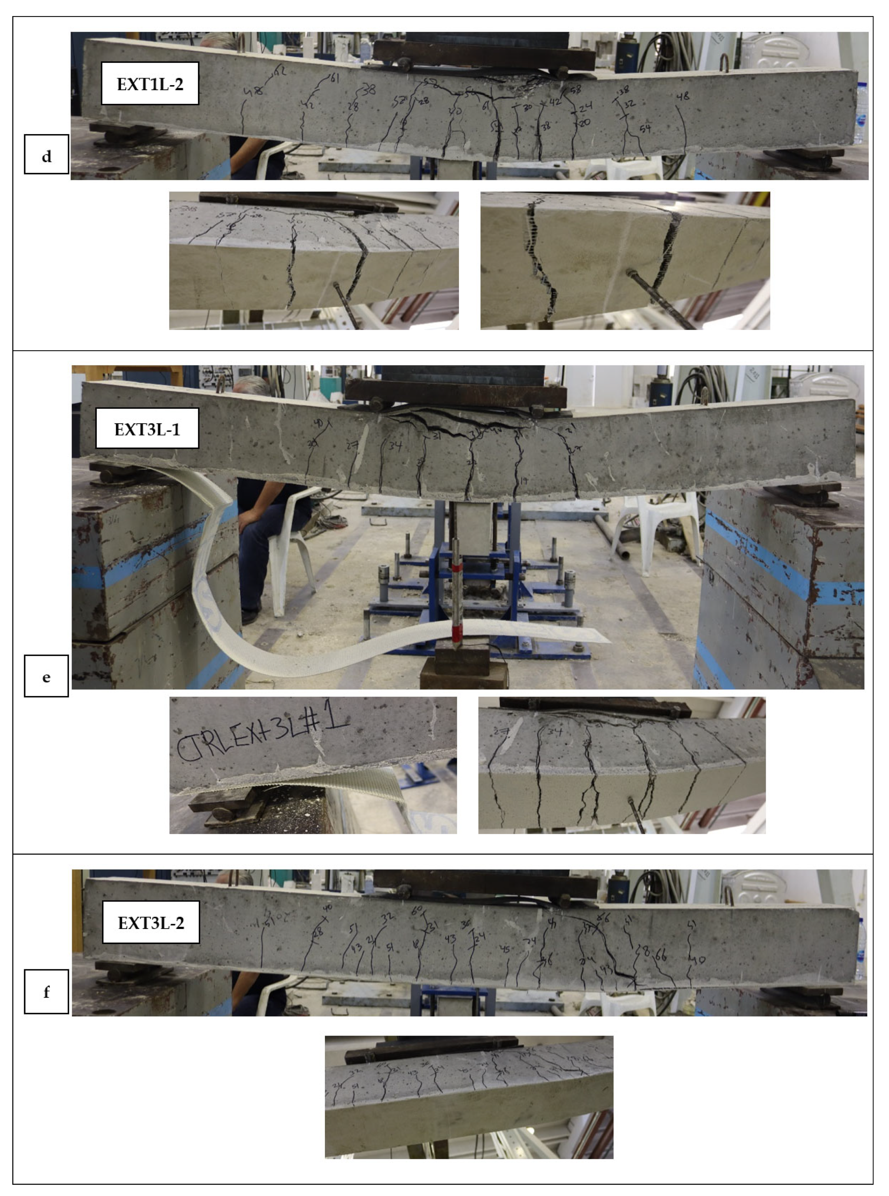
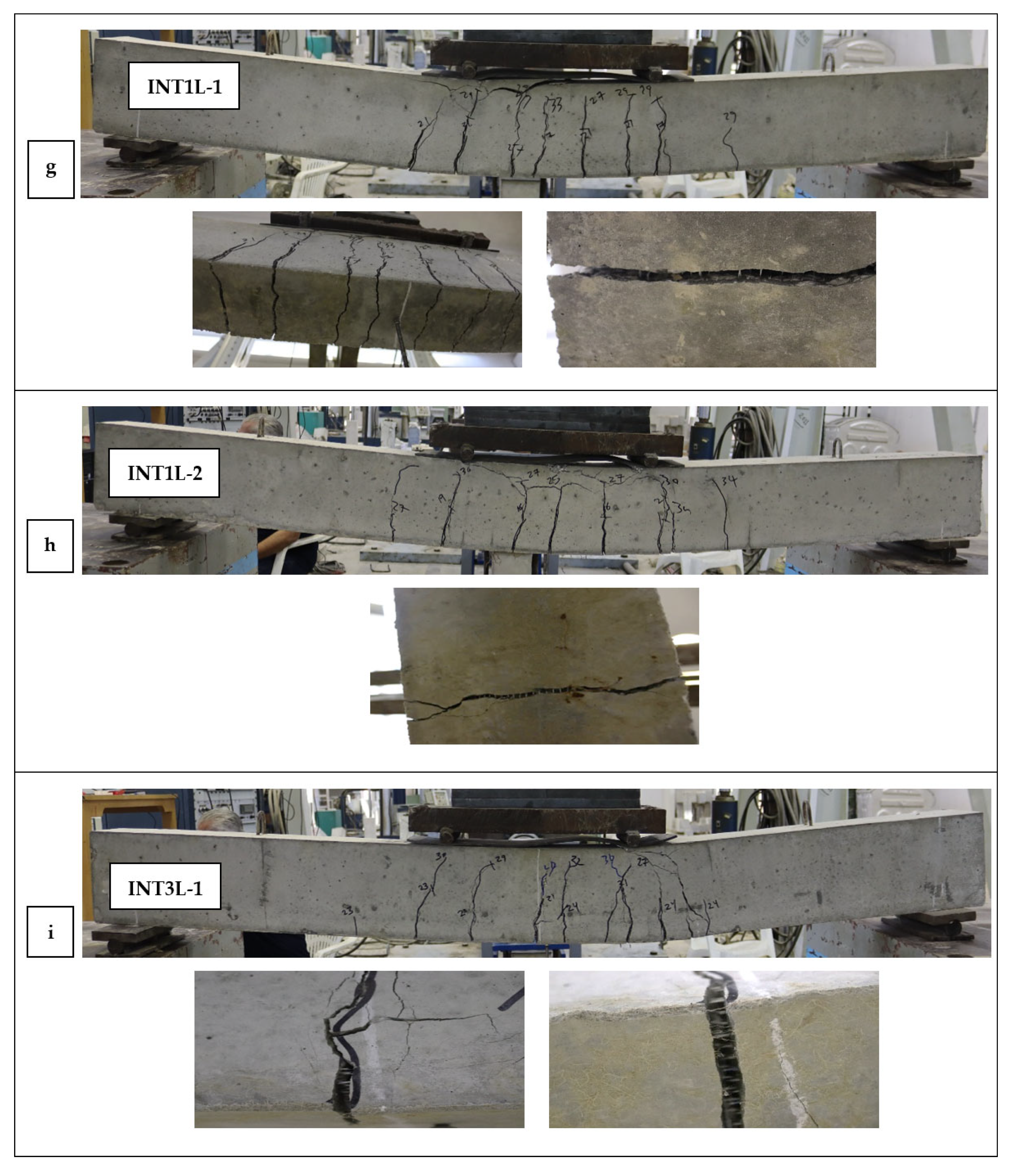
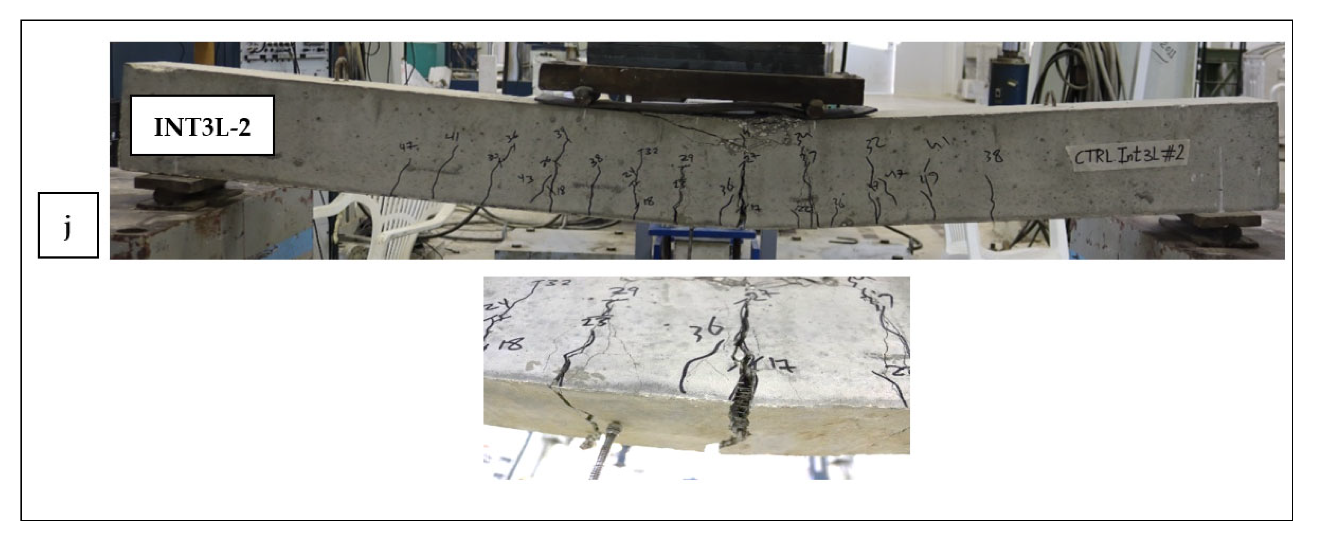
Table 3 summarizes the outcomes for every tested beam, listing the ultimate failure loads, matching midspan deflections, and the percentage rise in strength achieved using the retrofit material. Previously reported load–deflection patterns are displayed in Figure 7. The load–deflection responses of all strengthened beams, together with those of the CTR samples, are plotted in Figure 8. Furthermore, the final observed failure modes are visually presented in Figure 9.
It is fully acknowledged that the limited number of large-scale specimens per configuration (two specimens) restricts the statistical robustness of the study, which is primarily attributed to the large scale of the tested beams and the associated challenges in specimen preparation, handling, and experimental testing.

3.1. Load-Deflection Curves

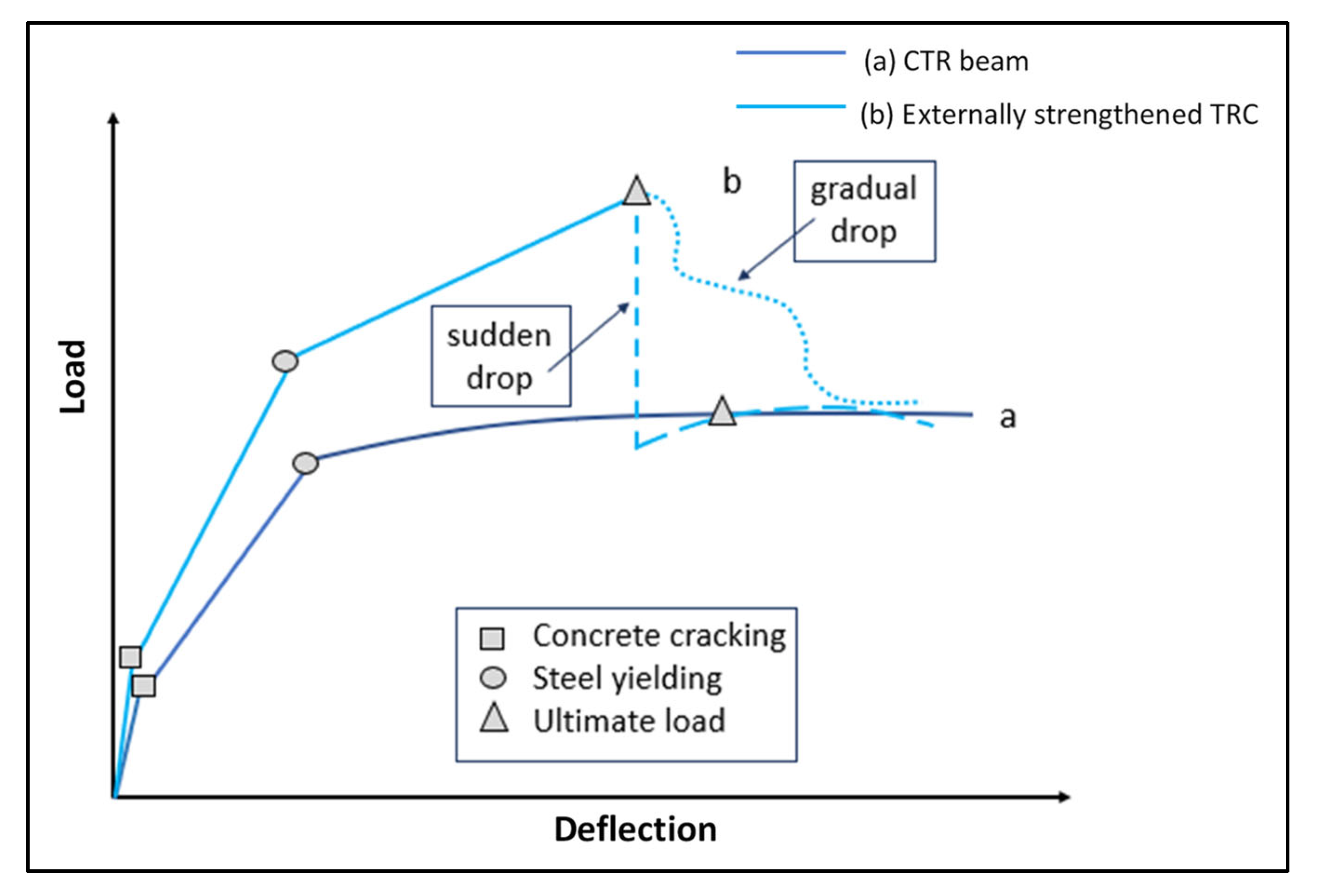
According to previous studies, the load–deflection responses of CTR beams and externally strengthened TRC beams under bending behave as simplified in Figure 7, shown as curves a and b, respectively. The TRC response curves display three clear phases: (1) an initial stage during which the beam remains uncracked; (2) a cracking progression phase continuing until yielding of the internal steel reinforcement; and (3) a post-yielding phase leading up to failure, characterized by plastic hinge formation in non-strengthened beams or, in strengthened beams, full activation of the textile until the ultimate load is reached.
In some studies, the addition of strengthening layers results in greater initial stiffness during the uncracked phase (Figure 7) [34,42,56,57,58,59,60,61], whereas in others, the improvement is minimal. The literature also indicates that the concrete cracking load at the end of Stage One increases in strengthened beams [42,57,58,60], suggesting early fiber engagement before concrete cracking. During Stage Two, widespread cracking activates the textile layers, resulting in a stiffer response and a higher yield load than in the CTR beams [42,51,54,55,61,62,63,64]. In Stage Three, once the steel yields, the textile accounts for a growing share of flexural resistance, sustaining most of the additional load until failure. A few exceptions, such as diagonal shear failure or concrete crushing, occur when the strengthening capability is lost. Ultimately, flexural strength tends towards the CTR beam’s plastic moment capacity due to significant degradation.
Figure 8 presents the load–deflection profiles for all tested and CTR beams. As shown, the CTR samples (CTR-1 and CTR-2) followed the conventional CTR response described in previous studies. CTR-1 and CTR-2 recorded ultimate loads of 37.22 and 34.13 kN, with midspan deflections of 45.46 and 46.13 mm, respectively. Their mean ultimate load and deflection were 35.68 kN and 45.8 mm.
For the EXT1L specimens (EXT1L-1 and EXT1L-2), Figure 7 and Figure 8 show that the strengthening effect became pronounced in Stages Two and Three during flexural crack propagation. During Stage Two, both steel and textile reinforcements were in tension, contributing to enhanced flexural strength. In Stage Three, the steel contribution remained generally unchanged, apart from slight hardening post-yield, while greater textile mobilization in tension became the dominant source of added capacity. Post-yield behavior was similar for both samples, and the load dropped back to CTR levels at failure, signaling complete loss of strengthening action. EXT1L-1 and EXT1L-2 reached ultimate loads of 53.52 and 63.01 kN, with respective deflections of 34.19 and 32.36 mm, representing flexural increases of 50 and 76.6% over the mean CTR strength.
The load–displacement trend for the EXT3L-2 specimen was similar to that of the two EXT1L specimens. It demonstrated an ultimate strength of 67.92 kN with a corresponding deflection of 28.86 mm, and 90.4% enhancement in the flexural capacity over the average flexural capacity of the CTR specimens. However, the load–displacement curve for the EXT3L-1 followed the same trend as the CTR specimens (Figure 8) due to the early separation of the external strengthening layers during testing (Figure 9e). Accordingly, the strengthening material had no effect on the load–displacement curve, in contrast to what was reported for other EXT beams. This specimen also reported an ultimate load of 40.68 kN, which was close to the value recorded for the CTR specimens, with a corresponding deflection of 39.54 mm.
The load–displacement trends of the INT1L-1 and INT1L-2 specimens showed the same performance as that of the two CTR specimens. No improvement in flexural capacity was reported as the INT1L-1 and INT1L-2 specimens demonstrated an ultimate strength of 36.56 and 36.28 kN, respectively, with corresponding deflections of 54.63 and 52.14 mm. This indicates that INT1L does not sufficiently affect the flexural capacity of beams.
The load–displacement trend of the INT3L-2 specimen demonstrated an ultimate strength of 51.87 kN with a corresponding deflection of 21.8 mm, showing a 45% enhancement in flexural capacity over the average of the CTR specimens. Its behavior resembled that of externally retrofitted beams, but after reaching the post-peak point, the capacity gradually dropped. In contrast, the load–displacement curve for the INT3L-1 specimen showed an ultimate load of 33.75 kN, which was close to the value recorded for the CTR specimens, with a corresponding deflection of 43.1 mm. The curve followed a similar trend to the CTR specimen, indicating textile slippage due to incomplete embedding in the mortar, which likely hindered effective stress transfer.

3.2. Failure Modes

Numerous failure mechanisms are documented in prior research, reflecting the intricate mechanical response of textile-based strengthening. The observed failure modes for the beams in this study are shown in Figure 9.
The CTR beams experienced flexural failure after the development of major bending cracks at the zone of peak moment; this occurred when the tensile steel yielded, followed by crushing of the compression-zone concrete (Figure 9a,b).
In the EXT1L sample, failure occurred through textile rupture at the location of maximum moment (Figure 9c,d). Under high tensile forces in this zone, the textile fibers snapped within a concentrated region. This produced a brittle failure pattern, marked by a sudden capacity loss clearly visible in the load–displacement trace of these beams.
For the EXT3L group, specimen EXT3L-1 failed from separation along the concrete–matrix interface (Figure 9e). This debonding mechanism arose from the breakdown of adhesion between the matrix layer and the underlying concrete. The detachment initiated from the support region, propagating toward the midspan, which is referred to as end debonding. The load dropped suddenly in this case, indicating the brittle nature of debonding. In this specimen, full detachment occurred early in the testing, which caused the load–displacement curve to resemble that of the CTR specimen, as the strengthening had no opportunity to engage. However, the EXT3L-2 specimen remained intact until failure, with no fiber rupture observed (Figure 9f). It exhibited the highest enhancement in ultimate load among all beams, highlighting the critical importance of carefully attaching fibers when used externally.
Carefully attaching the fibers refers to ensuring proper surface preparation, correct positioning of the textile, and full impregnation of the mesh with mortar to achieve adequate bond. This includes (1) cleaning and roughening the beam surface to promote adhesion, (2) applying a continuous and uniform first mortar layer before laying the textile, (3) gently pressing the textile into the fresh mortar to eliminate voids and ensure full contact, (4) maintaining correct alignment without wrinkles or slack, and (5) applying additional mortar layers to fully embed the textile.
Previous studies have demonstrated that debonding in externally strengthened RC members may occur through several distinct modes, depending on the properties of the textile, matrix, and substrate, as well as the quality of the bond at the interfaces. D’Ambrisi and Focacci [51] classified the loss of strengthening effectiveness into four principal modes: (a) intermediate debonding within the concrete substrate, typical of FRP-strengthened beams; (b) fiber–matrix debonding accompanied by significant fiber slippage, commonly observed in FRCM systems; (c) sudden detachment at the matrix–concrete interface without concrete involvement, representing a brittle failure mode; and (d) delamination within the textile or matrix layer following progressive slip.
In the present study, the observed failure of the debonded specimen corresponds to Mode (c), characterized by sudden detachment of the textile– adhesive layer at the concrete interface in the maximum bending moment region, without noticeable cracking or crushing of the concrete substrate. Similar brittle debonding behavior has been widely reported in the literature when adequate anchorage is not provided. D’Ambrisi and Focacci [51] observed premature detachment at the matrix–concrete interface in FRCM-strengthened beams lacking end anchorage, which limited the effectiveness of the strengthening system. Furthermore, Escrig et al. [58] demonstrated that removing the weak surface layer of concrete and anchoring the FRCM using U-jacket systems at the ends of the external reinforcement significantly improved bond performance and effectively prevented debonding failures. Comparable conclusions were also reported by Elsanadedy et al. [43], who showed that the provision of end U-anchorage was efficient in precluding or delaying TRM end debonding. These findings support the qualitative explanations provided in the present study and confirm that inadequate anchorage, insufficient stress transfer length, and localized bond deficiencies at the textile–mortar–concrete interface can govern premature debonding, even when the concrete substrate remains intact. In the current study, it should be noted that the proposed explanations related to bond quality, textile alignment, and mortar impregnation are inferred from the observed experimental behavior and should be considered hypotheses, requiring further validation through dedicated experimental investigations.
For the INT1L specimens, fiber rupture was observed through the crack formed in the region of maximum moment (Figure 9g). Upon closer inspection of the crack, it was found that the textile fibers inside had ruptured. While the fibers worked in conjunction with the main reinforcement, the single layer of textile did not significantly impact the strength, as evidenced by the load–displacement curve. The lack of substantial enhancement in strength suggests that one layer of internal textile is insufficient to effectively contribute to the overall load-bearing capacity.
For the INT3L series, specimen INT3L-1 failed as a result of fiber pull-out within the concrete (Figure 9h). This pull-out happened in the high-moment region, causing a sharp loss in load capacity due to the end of the strengthening effect. The load–displacement plot showed a response close to that of the CTR beam, suggesting the textile offered little improvement in load resistance. Conversely, specimen INT3L-2 failed by fiber breakage (Figure 9i). Its load–displacement profile revealed that the fibers were firmly anchored in the concrete matrix, with no evidence of slippage. In this case, the textile reinforcement worked effectively in conjunction with the main steel reinforcement, as evidenced by a more gradual and smoother drop in strength compared to the EXT specimens.
In addition to the observed failure mechanisms, noticeable variability was recorded between duplicate specimens within the same strengthening configuration, particularly in the EXT3L and INT3L groups. This variation is primarily attributed to differences in installation quality and bonding conditions, which play a critical role in the performance of textile-reinforced systems. Factors such as surface preparation, textile alignment, degree of mortar impregnation, and compaction can significantly influence the effectiveness of stress transfer between the textile, mortar, and concrete substrate. For instance, the premature debonding observed in one of the EXT3L specimens prevented proper activation of the textile layers, resulting in behavior comparable to the control beam. Similarly, in the INT3L group, insufficient embedding and possible slippage of the textile within the concrete matrix limited its contribution in one specimen, while proper integration in the other specimen led to enhanced performance. These findings highlight the sensitivity of textile-based strengthening techniques to workmanship and execution quality, emphasizing the necessity for strict quality control during installation to ensure consistent and reliable structural performance.
Despite these promising performance observations, the use of textile reinforcement is associated with several limitations and risks, including sensitivity to installation quality, variability in bond performance, and the potential for premature debonding or slippage, which can significantly reduce the effectiveness of the strengthening system. From a practical perspective, the wider implementation of textile-reinforced systems remains limited due to the absence of well-established design codes, standardized testing procedures, and unified installation guidelines, highlighting the need for further research and development to support their adoption in engineering practice.

4. Numerical Modeling

This section outlines a calibrated 3D nonlinear finite element analysis (FEA) developed from the measured responses of beams tested experimentally and strengthened using either INT or EXT systems in combination with steel reinforcement. Such models enable parametric investigations to assess the influence of variables not examined experimentally on the flexural strength of RC beams. The study utilized Abaqus® 6.13 to create the finite element representations [49]. The adopted modeling approach assumes a perfect bond between the textile reinforcement and the surrounding matrix. This assumption is supported by experimental observations, which show that the dominant failure mode for most specimens was textile rupture at the location of maximum moment, indicating effective stress transfer and bond integrity up to failure. Only one specimen exhibited premature debonding, which was attributed to variability in surface preparation and the application of the external strengthening system.

4.1. Finite Element Scheme

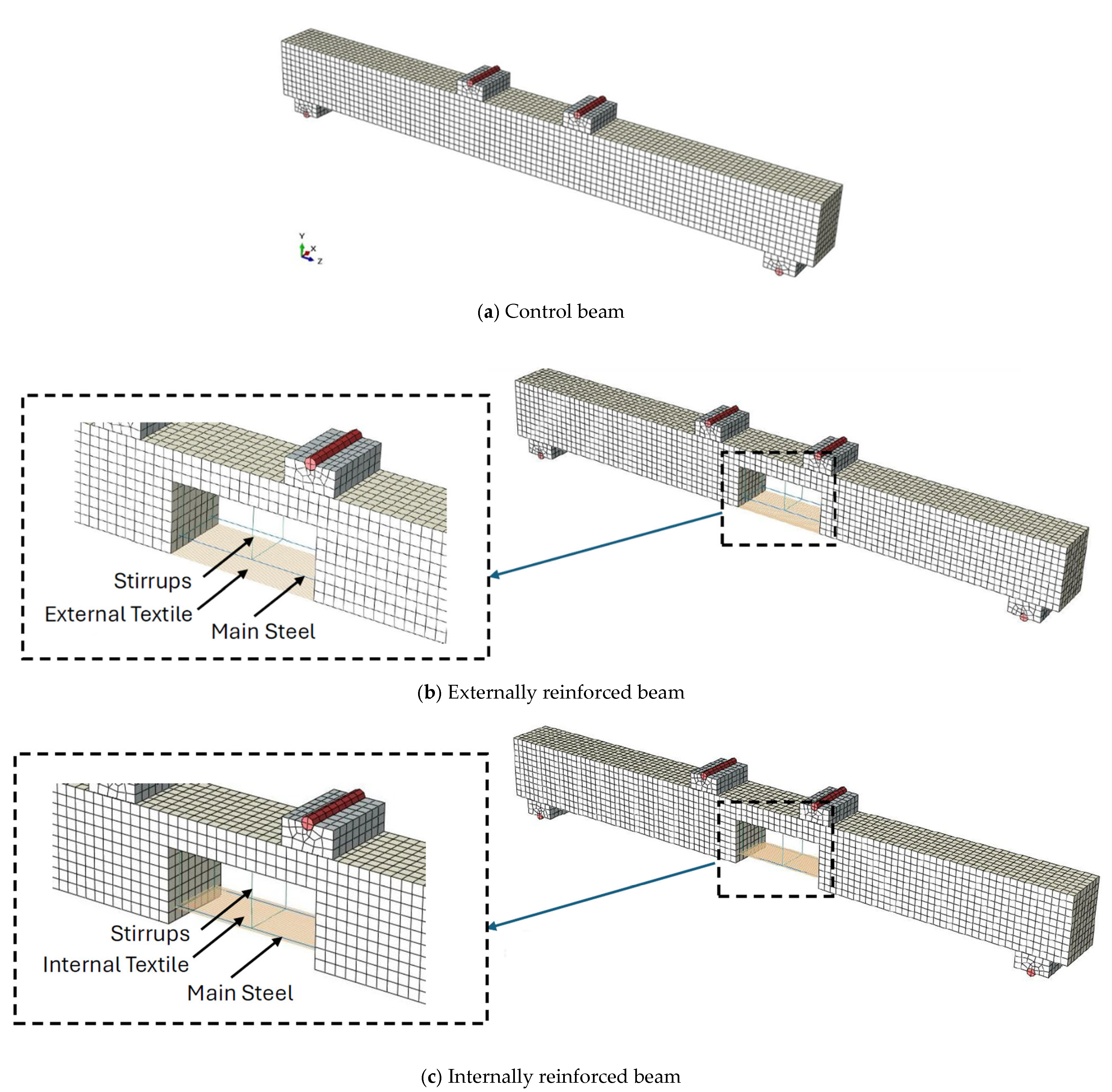
The RC beams were represented as steel reinforcement truss elements embedded within eight-node, 3D solid concrete elements using reduced integration and hourglass control. In the INT-strengthened beams, the textile was likewise modeled as a truss element embedded alongside the steel bars. An embedded constraint ensured that the motion of the embedded components, steel or textile, matched the interpolated displacements of the surrounding concrete host elements (Abaqus® 6.13) [49]. For the EXT models, a tie constraint was applied, securing the textile to the beam’s underside. Figure 10 provides the Abaqus® details of the modeled beams [49].
The tie constraint neglects local slip and progressive interface degradation, which can play a significant role in the overall behavior, particularly in specimens where bond failure mechanisms are more pronounced. However, due to the limited number of specimens exhibiting such failure modes, the use of the tie constraint is considered acceptable for the present study.

4.2. Concrete Constitutive Model

Concrete’s brittle response was simulated through the concrete-damaged plasticity (CDP) constitutive model. This approach describes concrete’s inelasticity using isotropic damage concepts along with isotropic tensile and compressive plasticity (Abaqus® 6.13) [49]. The CDP formulation, grounded in continuum damage mechanics, combines scalar damaged elasticity with isotropic plasticity under tension and compression to capture the full inelastic range of concrete behavior [65]. It effectively represents tensile and compressive responses, with the yield surface governed by a Drucker–Prager–type yield function. The loading function introduced by Lubliner et al. [65] was later adapted by Lee and Fenves [66] to model changes in tensile and compressive strengths over time.
Concrete’s uniaxial stress–strain relationship in both compression and tension was modeled using Tsai’s equation [67] as detailed below:
y = n   ·   x 1   +   n     r r 1   x   +   x r r 1
In this formulation, y denotes the ratio of concrete stress to its peak value at any point along the curve, while x is the ratio of concrete strain to the strain at peak stress. The curve’s profile is governed by the parameters n and r. According to Chang and Mander [68], the proposed equation offers both flexibility and general applicability, allowing control over the ascending and descending branches for both confined and unconfined concrete systems. In this research, the same formulation was adopted to represent concrete behavior in both tension and compression. This constitutive model has also been employed by various researchers in the simulation of different structural elements, including RC flat slabs [69] and concrete-filled steel tubes [70,71].
For the compression regime in the present study, the concrete was initially modeled as exhibiting a linear-elastic response, with a slope equal to its modulus of elasticity, up to a stress level of 0.45 f c ' . Beyond this stress threshold, the inelastic response was defined by the material’s hardening phase (ascending branch) followed by its softening phase (descending branch). The corresponding parameters describing the compressive behavior of concrete, as governed by Equation (1), were specified as follows:
y = f c f c '
x = c c '
n = 7.2 f c ' 3 / 8
In the present study, the tensile response of concrete was represented as a linear-elastic behavior up to its tensile strength, with the modulus of elasticity defined by E c   = 8200 f c ' 3 / 8 . Once the tensile capacity was exceeded, the post-cracking behavior was modeled using various constitutive relationships examined by Allouzi et al. [72]. This post-failure modeling incorporates the effects of tension stiffening, which captures the mechanical interaction between the reinforcement and surrounding concrete, as well as the mechanism of load transfer from the cracked concrete to the reinforcement. For the purposes of this research, the adopted post-failure law followed the form of Equation (1), with the parameters governing the tensile behavior of concrete specified accordingly.
y = f t f t '
x = t t '
n = E c t f t
r = f c ' 5.2 1.9

4.3. Reinforcement Constitutive Model

At the onset, both the steel and the textile glass exhibited linear-elastic behavior, characterized by a modulus of elasticity of 200,000 MPa for the steel and 70,000 MPa for the textile glass. This linear response continued up to their respective yield strengths, which were 280 MPa for steel and 210 MPa for textile glass. Beyond these yield points, the materials were modeled to follow an idealized perfectly plastic response.

4.4. Mesh Sensitivity

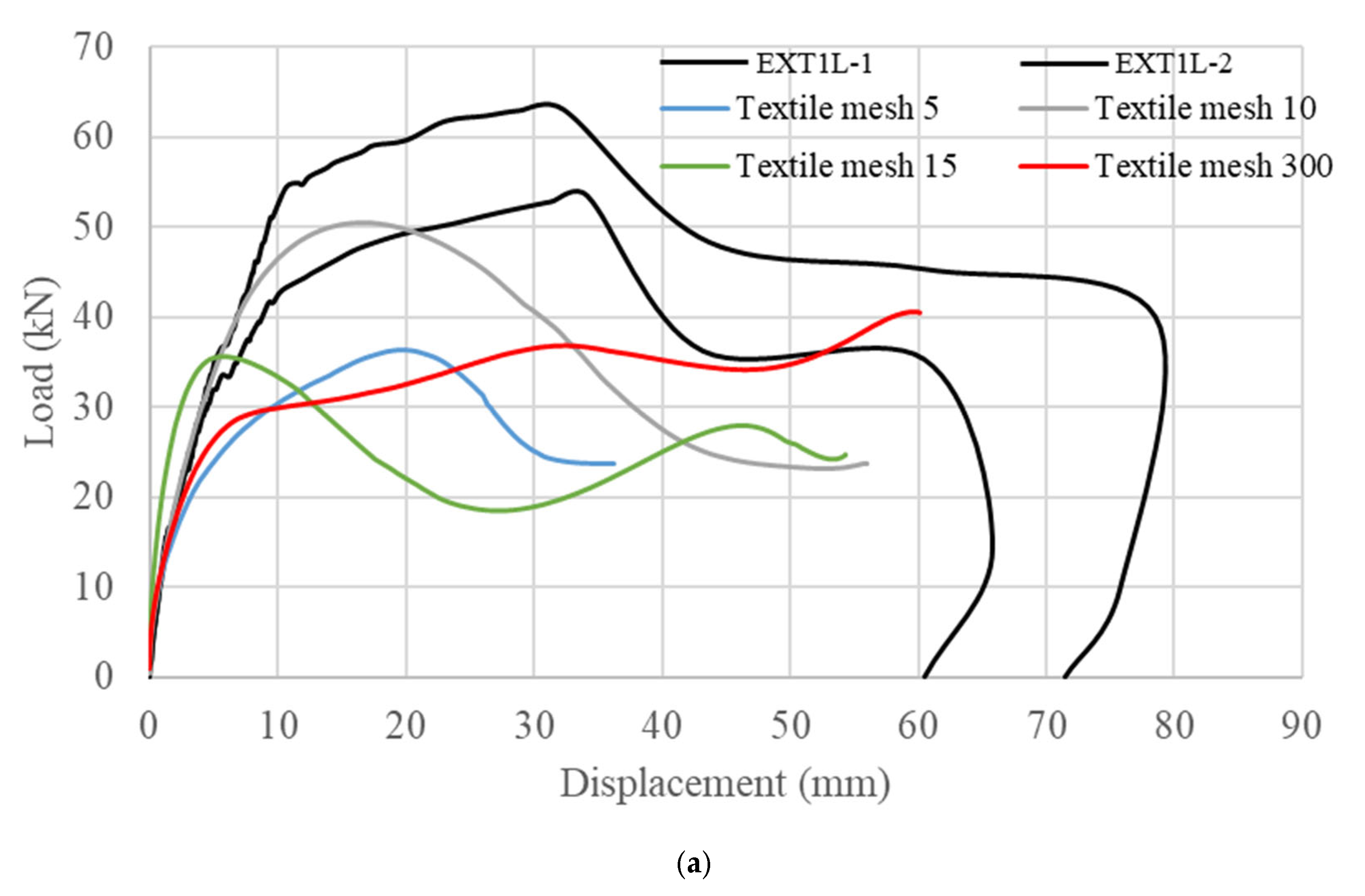
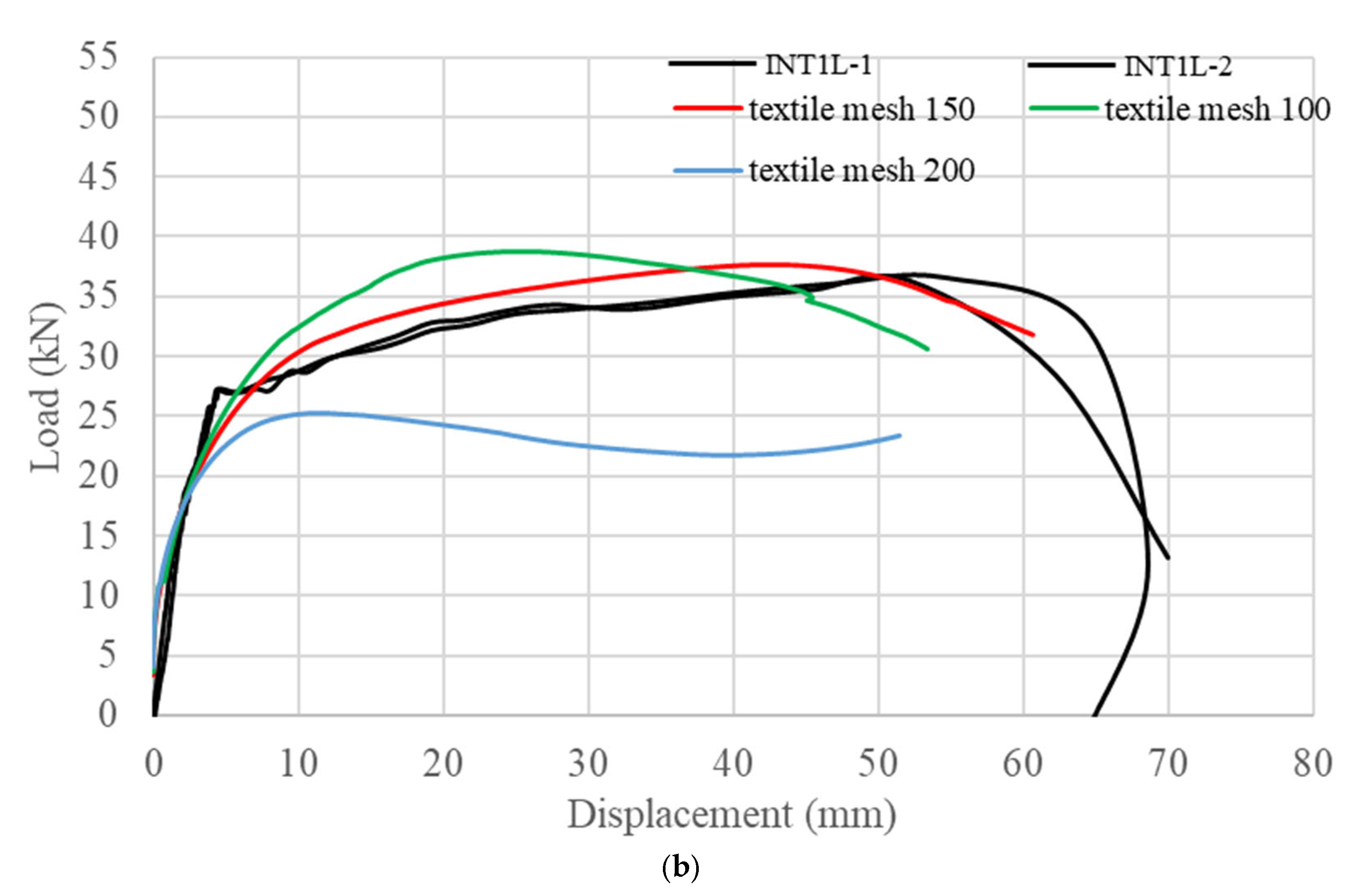
A mesh sensitivity analysis was conducted to evaluate the influence of textile mesh size on the numerical response of two specimens: the externally strengthened one-layer specimen (EXT1L) and internally strengthened one-layer specimen (INT1L). Several mesh sizes were considered for textile reinforcement, while keeping all other modeling parameters constant.
The numerical load–deflection responses obtained from the different mesh sizes were compared with the corresponding experimental results, as shown in Figure 11. It can be observed that the mesh size significantly affects the predicted structural response, particularly in terms of stiffness, peak load, and post-peak behavior.
The model with a mesh size of 10 provided the closest agreement with the experimental curves for EXT1L and 150 for INT1L, and could capture both the pre-peak stiffness and the ultimate load, as well as the post-peak softening response. For the externally strengthened specimen, it is explicitly acknowledged that the current finite element model does not capture key interface behaviors, such as bond–slip relationships and debonding propagation. This limitation explains the reduced level of convergence achieved compared to the INT1L specimen, and it should be considered in future research using sufficient specimens for calibration that encounter bond-slip issues. A finer mesh (mesh size = 5) did not result in a noticeable improvement in accuracy but led to increased computational cost. On the other hand, coarser meshes (mesh sizes = 15 and 300) showed deviations in stiffness and load-carrying capacity.
Very good agreement between INT1L and the experimental results is evident, achieved at a lower computational cost.

4.5. Results of the Finite Element Analysis (FEA)

Load–Displacement Curves

The FEA outcomes for the tested specimens are illustrated in Figure 8. The simulated load–displacement responses for the CTR, EXT, and INT configurations exhibited strong correlation with the corresponding experimental observations. In the case of the CTR specimen, the numerical load–displacement profile closely mirrored the experimentally obtained curve, with the peak load predicted by the analysis reaching 34.5 kN, which is very close to the average experimental ultimate strength of 35.5 kN. Furthermore, the general shape and progression of the simulated curve were found to align closely with those recorded during the physical tests.
Regarding the EXT specimens, the EXT1L specimen showed a maximum capacity of 50.5 kN, compared to an average experimental strength of 58 kN. For the EXT3L specimen, the maximum capacity was 55 kN, while the experimental value was 77 kN. The trends in both cases were comparable, with both curves reaching a maximum load before experiencing a drop until failure. However, the FEA did not fully capture the behavior observed in the experiments. In the FEA model, the EXT specimens were modeled as a grid mesh attached to the beam’s surface. In contrast, the experimental setup used glue that filled the gaps and held the mesh in place, resulting in a more uniform layer attached to the bottom surface of the beam. This difference led to a deviation, particularly for the EXT3L specimen, where additional mortar was applied, but this discrepancy was expected. Overall, the FEA predictions were still considered acceptable and conservative in predicting the beam behavior.
For the INT specimens, the maximum load for the INT1L specimen was 38 kN, compared to an average of 36.4 kN from experimental results, with the curve closely following the experimental trend. This behavior was consistent with the CTR specimen, indicating that one layer of INT did not significantly impact the beam’s capacity. For the INT3L specimen, the maximum capacity was 44 kN, while the experimentally observed capacity was 52 kN. The load–displacement curves from both the FEA and experiments showed a similar trend, with a gradual drop in capacity after reaching the ultimate load. The quantitative error metrics to evaluate the model performance are presented in Table 4.

5. Discussion of Novelty and Originality in the Present Study

This section presents a comparative discussion of the novelty and originality of the present study in relation to previously published research. A comprehensive analytical comparison is provided in Table 5, which summarizes key parameters including textile type, strengthening approach, number of layers, failure mechanisms, and achieved structural performance.
Based on the comparative analysis presented in Table 4, the originality and distinct contribution of the present study can be highlighted through the following key aspects:
  • All seven comparison studies in this table examined only external strengthening. The present study is therefore unique in directly comparing internal and external AR-glass textile reinforcement under identical conditions, same beam geometry, concrete strength, loading setup, and textile material.
  • The 90% flexural capacity increase achieved by EXT3L exceeds the gains reported by most comparable studies. Raoof et al. [42] found that TRM was 46–80% as effective as FRP and that tripling layers nearly doubled effectiveness, but their absolute capacity gains with glass textile were lower than those in the present study. Giese et al. [73] reported up to 72% with 4 AR-glass layers, and Moy and Revanna [74] only 30–32% even with 5 basalt/carbon TRM layers. The present study’s higher gains may reflect specific textile properties, the mortar system, or the beam configuration, but the result is notable.
  • The use of duplicates per configuration is rare in this literature. Raoof et al. [42] tested 13 beams, but without duplicates. The present study’s candid documentation that nominally identical EXT3L and INT3L specimens produced dramatically different results (one achieving 90% gain, the other 0% due to debonding) provides critical evidence about the practical reliability of textile strengthening, a finding that single-specimen studies cannot capture.
  • While Shah et al. [75] and Elsanadedy et al. [43] also used FEA, their models covered only external configurations. Raoof et al. [42] used an analytical approach (fib Model Code formula) rather than full FEA. The present study’s Abaqus® CDP model spans both internal and external textile configurations, providing broader numerical validation [49].

6. Conclusions

The feasibility of applying GFG to RC beams was explored through both experimental trials and numerical simulations using FEA modeling. In these investigations, the textiles were integrated into the beams in two distinct ways: as an external strengthening measure by adhering one or three layers to the outer beam surface, and as an internal reinforcement placed alongside the primary steel bars, again in configurations of one or three layers. From these studies, the following findings emerged:

6.1. Scientific Findings

  • Employing external layers, affixed with mortar to the surfaces of RC beams, proved to be a more efficient strengthening method than embedding layers internally.
  • In terms of structural performance, applying a single external layer led to an average increase of 63% in flexural capacity, as measured from two tested specimens.
  • The use of three external layers achieved a higher improvement of 90% in flexural capacity.
  • The use of one internal layer did not impact the ultimate capacity and had no effect, meaning that one layer is not enough, but using three internal layers improved the capacity by 45%.
  • The failure mechanisms of textile-strengthened beams varied between textile rupture, debonding, and slippage, confirming that bond behavior is a governing factor in determining structural response.
  • The developed finite element model showed good agreement with experimental results in terms of load–displacement behavior and ultimate capacity, although its accuracy is limited by the assumption of perfect bond.

6.2. Applied (Practical) Findings

  • External application of textile reinforcement using a cementitious matrix provides an effective and practical method for strengthening RC beams, achieving significant improvements in flexural capacity when proper installation is ensured.
  • The bonding procedure demands particular attention, as incorrect application can cause the entire textile layer to detach, which in turn may lead to the complete separation of the reinforcement from the concrete substrate. To safeguard the durability and effectiveness of this approach, it is critical to employ appropriate adhesives and maintain close oversight throughout the installation process.
  • In the use of external layers, the load–displacement profiles demonstrated that, after reaching peak capacity, the load-carrying ability of the beams decreased markedly. This underlines the necessity for precise positioning and proper mortar application when attaching the textile to the beam’s exterior, since any detachment of the reinforcement layer can entirely nullify the strengthening effect. Such detachment was, in fact, recorded in one of the EXT3L specimens.
  • Internal textile reinforcement showed limited effectiveness unless adequate embedding and bond conditions were achieved, highlighting the need for improved detailing and placement techniques.
  • It should be noted that the internal grid must be well embedded in the concrete matrix to avoid any separation and slippage between the layers and the concrete, as separation will affect the capacity, and the textile mesh will not work with the main steel as reinforcing. This was observed in one of the specimens with three internal layers.
The applicability of the findings in this study is limited by the specific materials and configuration examined. The research focused on a single type of textile reinforcement, unidirectional alkali-resistant (AR) glass fiber with a fixed mesh geometry, applied to beams cast with one concrete strength (50 MPa) and one structural configuration (150 × 200 × 2000 mm beams under four-point bending). As a result, key parameters known to influence the performance of textile-reinforced systems were not explored. These include textile architecture (e.g., bidirectional grids, different fiber types, or coated versus uncoated yarns), variations in concrete substrate strength, particularly relevant for retrofitting older or deteriorated structures, and geometric factors such as shear span-to-depth ratio, which can alter the governing failure mode. Therefore, the conclusions drawn herein should be considered valid only within the bounds of the tested materials, beam geometry, and loading configuration. Extrapolation to different concrete strengths, alternative textile products, or structural members with different dimensions and loading conditions should be done with caution. Broader applicability requires expanded future studies that systematically vary these influential parameters to establish more generalizable performance trends and design recommendations. The observed variability between duplicate specimens indicates that the repeatability of the results is influenced by several factors, including material variability and installation quality; therefore, the findings should be interpreted with caution, and further experimental studies with larger sample sizes are required to establish more robust conclusions.
Future research will focus on extending the present work by investigating different textile materials, including carbon and basalt fibers, as well as varying beam dimensions, textile orientations, and anchorage techniques to improve bond performance and structural efficiency. Despite its potential, the wider implementation of textile-reinforced systems requires further development of standardized design guidelines, testing procedures, and installation practices. Furthermore, future research may specifically address bond behavior between textiles, mortar, and concrete through dedicated bond-slip testing and the development of analytical and numerical interface models, enabling a more accurate and quantitative understanding of stress transfer mechanisms and debonding phenomena.
The current finite element model does not capture key interface behaviors, such as bond–slip relationships and the propagation of debonding. Future work should incorporate more advanced interface modeling approaches—such as cohesive zone models or bond–slip laws—to better represent the interaction between materials.

Author Contributions

Conceptualization, H.S.R., R.M.A. and M.B.B.; methodology, H.S.R., R.M.A., D.G.S., R.A.A. and H.H.A.; software, D.G.S. and R.A.A.; validation, R.M.A., D.G.S., R.A.A. and M.B.B.; formal analysis, R.M.A., D.G.S. and R.A.A.; investigation, H.S.R., R.M.A., D.G.S., R.A.A., M.B.B. and H.H.A.; resources, H.S.R. and H.H.A.; data curation, R.M.A., D.G.S., M.B.B. and H.H.A.; writing—original draft, H.S.R., R.M.A., D.G.S., R.A.A. and H.H.A.; writing—review and editing, H.S.R., R.M.A. and D.G.S.; visualization, H.S.R. and D.G.S.; supervision, H.S.R.; project administration, H.S.R., R.M.A. and M.B.B.; funding acquisition, H.S.R. and R.M.A. All authors have read and agreed to the published version of the manuscript.

Funding

This research received funding from Al-Zaytoonah University of Jordan, Amman, Jordan under Grant No. 08/23/2019-2020.

Data Availability Statement

The original contributions presented in this study are included in the article.

Acknowledgments

The authors would like to express their gratitude to the Deanship of Scientific Research at Al-Zaytoonah University of Jordan, Amman, Jordan, for funding this research. Additionally, they would like to extend their appreciation to ASSAS for Concrete Products Factory, Amman, Jordan, for their commendable efforts and support.

Conflicts of Interest

The authors declare no conflicts of interest.

References

  1. Al Marahla, R.H.; Shehzad, M.K.; Garcia-Taengua, E. Flexural and deflection behaviour of synthetic fibre reinforced concrete beams reinforced with glass fibre reinforced polymers bars under sustained service load. Structures 2023, 54, 946–955. [Google Scholar] [CrossRef]
  2. Al Marahla, R.H.; Shehzad, M.K.; Almarahlleh, N.H.; Aldmour, S.T.; Abendeh, R.M. Flexural performance of reinforced concrete beams incorporating polypropylene fibres: An experimental investigation and finite element model. Innov. Infrastruct. Solut. 2025, 10, 199. [Google Scholar] [CrossRef]
  3. Nimer, H.; Ismail, R.; Al-Mattarneh, H.; Khodier, M.; Jaradat, Y.; Rawashdeh, A.; Rawashdeh, M. Artificial neural networks and noncontact microwave NDT for evaluation of polypropylene fiber concrete. Asian J. Civ. Eng. 2025, 26, 273–292. [Google Scholar] [CrossRef]
  4. Ingham, J. Forensic engineering of fire-damaged structures. Proc. Inst. Civ. Eng. Civ. Eng. 2009, 162, 12–17. [Google Scholar] [CrossRef]
  5. Trapko, T.; Musiał, M. The effectiveness of CFRP materials strengthening of eccentrically compressed reinforced concrete columns. Arch. Civ. Mech. Eng. 2011, 11, 249–262. [Google Scholar] [CrossRef]
  6. Tran, H.; Balandraud, X.; Destrebecq, J.F. Improvement of the mechanical performances of concrete cylinders confined actively or passively by means of SMA wires. Arch. Civ. Mech. Eng. 2015, 15, 292–299. [Google Scholar] [CrossRef]
  7. Haddad, R.H.; Almasaeid, H.H. Recovering shear capacity of heat-damaged beams using NSM-CFRP strips. Constr. Build. Mater. 2016, 105, 448–458. [Google Scholar] [CrossRef]
  8. Hamilton, H.R.; Benmokrane, B.; Dolan, C.W.; Sprinkel, M.M. Polymer materials to enhance performance of concrete in civil infrastructure. Polym. Rev. 2009, 49, 1–24. [Google Scholar] [CrossRef]
  9. Bisby, L.; Chen, J.; Li, S.; Stratford, T.; Cueva, N.; Crossling, K. Strengthening fire-damaged concrete by confinement with fibre-reinforced polymer wraps. Eng. Struct. 2011, 33, 3381–3391. [Google Scholar] [CrossRef]
  10. Yaqub, M.; Bailey, C.; Nedwell, P. Axial capacity of post-heated square columns wrapped with FRP composites. Cem. Concr. Compos. 2011, 33, 694–701. [Google Scholar] [CrossRef]
  11. Al-Nimry, H.S.; Ghanem, A.M. FRP Confinement of Heat-Damaged Circular RC Columns. Int. J. Concr. Struct. Mater. 2017, 11, 115–133. [Google Scholar] [CrossRef]
  12. Alzeebaree, R.; Çevik, A.; Nematollahi, B.; Sanjayan, J.; Mohammedameen, A.; Gülşan, M.E. Mechanical properties and durability of unconfined and confined geopolymer concrete with fiber reinforced polymers exposed to sulfuric acid. Constr. Build. Mater. 2019, 215, 1015–1032. [Google Scholar] [CrossRef]
  13. Mohammedameen, A.; Gülşan, M.E.; Alzeebaree, R.; Çevik, A.; Niş, A. Mechanical and durability performance of FRP confined and unconfined strain hardening cementitious composites exposed to sulfate attack. Constr. Build. Mater. 2019, 207, 158–173. [Google Scholar] [CrossRef]
  14. Gulsan, M.E.; Mohammedameen, A.; Sahmaran, M.; Nis, A.; Alzeebaree, R.; Cevik, A. Effects of sulphuric acid on mechanical and durability properties of ECC confined by FRP fabrics. Adv. Concr. Constr. 2018, 6, 199. [Google Scholar]
  15. Jafari, A.; Shahmansouri, A.A.; Akbarzadeh Bengar, H. Hybrid CFRP-GFRP sheets for flexural strengthening of continuous RC beams: Experimentation and analytical modeling. Struct. Concr. 2025, 26, 972–993. [Google Scholar] [CrossRef]
  16. Ma, S. Advances in Mechanical Properties and Bonding Behavior of FRP-Reinforced Concrete Structures. J. Eng. Res. Rep. 2026, 28, 191–205. [Google Scholar] [CrossRef]
  17. Duarte, I.O.; Forti, N.C.D.S.; Pimentel, L.L.; Jacintho, A.E.P.G.D.A. A Study of the Shear Behavior of Concrete Beams with Synthetic Fibers Reinforced with Glass and Basalt Fiber-Reinforced Polymer Bars. Buildings 2024, 14, 2123. [Google Scholar] [CrossRef]
  18. Bywalski, C.; Drzazga, M.; Kaźmierowski, M.; Kamiński, M. Shear Behavior of Concrete Beams Reinforced with a New Type of Glass Fiber Reinforced Polymer Reinforcement: Experimental Study. Materials 2020, 13, 1159. [Google Scholar] [CrossRef]
  19. Hammad, M.; Bahrami, A.; Khokhar, S.A.; Khushnood, R.A. A state-of-the-art review on structural strengthening techniques with FRPs: Effectiveness, shortcomings, and future research directions. Materials 2024, 17, 1408. [Google Scholar] [CrossRef]
  20. Kabashi, N.; Muhaxheri, M.; Krasniqi, E.; Murati, Y.; Latifi, F. Advancements in fiber-reinforced polymer (FRP) retrofitting techniques for seismic resilience of reinforced concrete structures. Buildings 2025, 15, 587. [Google Scholar] [CrossRef]
  21. Ye, Y.-Y.; Smith, S.T.; Zeng, J.J.; Zhuge, Y.; Quach, W.M. Novel ultra-high-performance concrete composite plates reinforced with FRP grid: Development and mechanical behaviour. Compos. Struct. 2021, 269, 114033. [Google Scholar] [CrossRef]
  22. Yan, J.; Liu, Y.; Bai, F.; Ni, X.; Xu, Y.; Yan, Z.; Huang, F. Dynamic response of GFRP-reinforced UHPC beams under close-in blast loading. Mater. Des. 2022, 223, 111140. [Google Scholar] [CrossRef]
  23. Zeng, J.J.; Zeng, W.B.; Ye, Y.Y.; Liao, J.; Zhuge, Y.; Fan, T.H. Flexural behavior of FRP grid reinforced ultra-high-performance concrete composite plates with different types of fibers. Eng. Struct. 2022, 272, 115020. [Google Scholar] [CrossRef]
  24. Tao, X.; Guan, T.; Lu, X.; Zhang, P. Experimental Studies on Shear Behavior of FRP-UHPC Hybrid Beams. ce/Papers 2025, 8, 841–847. [Google Scholar] [CrossRef]
  25. Li, M.; Du, Y.; Li, M. Review on FRP strengthened concrete structures: Current advances, challenges and emerging innovations. Appl. Comput. Eng. 2025, 172, 18–28. [Google Scholar] [CrossRef]
  26. Zhang, L. Research Progress of Fiber Reinforced Polymers. Appl. Comput. Eng. 2025, 144, 1–9. [Google Scholar] [CrossRef]
  27. Gooranorimi, O.; Gremel, D.; Myers, J.J.; Nanni, A. Long-Term Durability of GFRP Internal Reinforcement in Concrete Structures. Spec. Publ. 2019, 331, 69–79. [Google Scholar]
  28. Fergani, H. Durability and Long-Term Structural Performance of GFRP Bars in Concrete. Doctoral Dissertation, University of Sheffield, Sheffield, UK, 2017. [Google Scholar]
  29. Gajdošová, K.; Sonnenschein, R.; Blaho, S.; Kinčeková, S.; Pecka, J. Durability of FRP reinforcements and long-term properties. Slovak J. Civ. Eng. 2020, 28, 50–55. [Google Scholar] [CrossRef]
  30. Ibrahim, B.; Elzefzafy, H.; Mohamed, H.M. Sustainable Making Decision in Design of Concrete Tunnels Using Durable FRP Reinforcement. In 2024 International Conference on Decision Aid Sciences and Applications (DASA); IEEE: Piscataway, NJ, USA, 2024; pp. 1–4. [Google Scholar]
  31. Triantafillou, T.C.; Papanicolaou, C.G. Textile Reinforced Mortars (TRM) versus Fiber Reinforced Polymers (FRP) as Strengthening Materials of Concrete Structures. ACI Spec. Publ. 2005, 230, 99–118. Available online: https://quakewrap.com/frp%20papers/TextileReinforcedMortars(TRM)versusFiberReinforcedPolymer(FRP)asStrengtheningMaterialsofConcreteStructures.pdf (accessed on 8 April 2026).
  32. Triantafillou, T. (Ed.) Textile Fibre Composites in Civil Engineering; Woodhead Publishing: Cambridge, UK, 2016. [Google Scholar]
  33. Papanicolaou, C.G.; Triantafillou, T.C.; Bournas, D.A.; Lontou, P.V. TRM as strengthening and seismic retrofitting material of concrete structures. In Textile Reinforced Concrete, Proceedings of the 1st International RILEM Symposium, RILEM Proceedings PRO050, Aachen, Germany, 5–7 September 2006; RILEM Publications: Marne la Vallée, France, 2006; Volume 50, pp. 331–340. [Google Scholar] [CrossRef]
  34. Papanicolaou, C.; Triantafillou, T.; Papantoniou, I.; Balioukos, C. Strengthening of two-way reinforced concrete slabs with textile reinforced mortars (TRM). In Proceedings of the 4th Colloquium on Textile Reinforced Structures (CTRS4), Dresden, Germany, 3–5 June 2009; pp. 409–420. Available online: https://nbn-resolving.org/urn:nbn:de:bsz:14-ds-1244048746186-75760 (accessed on 8 April 2026).
  35. Peled, A.; Mobasher, B.; Bentur, A. Textile Reinforced Concrete; CRC Press: Boca Raton, FL, USA, 2017. [Google Scholar]
  36. Kruger, M.; Ozbolt, J.; Reinhardt, H.W. A new 3D discrete bond model to study the influence of bond on structural performance of thin reinforced and prestressed concrete plates. In Proceedings of the High Performance Fiber Reinforced Cement Composites (HPFRCC4), Ann Arbor, MI, USA, 16–18 June 2003; pp. 49–63. [Google Scholar]
  37. Peled, A.; Bentur, A.; Yankelevsky, D. Flexural performance of cementitious composites reinforced with woven fabrics. J. Mater. Civ. Eng. 1999, 11, 325–330. [Google Scholar] [CrossRef]
  38. Peled, A.; Bentur, A. Geometrical characteristics and efficiency of textile fabrics for reinforcing cement composites. Cem. Concr. Res. 2000, 30, 781–790. [Google Scholar] [CrossRef]
  39. Häußler-Combe, U.; Jesse, F.; Curbach, M. Textile reinforced concrete-overview, experimental and theoretical investigations. In Fracture Mechanics of Concrete Structures, Proceedings of the Fifth International Conference on Fracture Mechanics of Concrete and Concrete Structures (FraMCoS-5), Vail, CO, USA, 12–16 April 2004; AEDIFICATIO Publications: Freiburg, Germany, 2004; Volume 204, pp. 12–16. [Google Scholar]
  40. Meyer, C.; Vilkner, G. Glass concrete thin sheets prestressed with aramid fiber mesh. In Proceedings of the High Performance Fiber Reinforced Cement Composites (HPFRCC4), Ann Arbor, MI, USA, 16–18 June 2003; pp. 325–336. [Google Scholar]
  41. Koutas, L.N.; Tetta, Z.; Bournas, D.A.; Triantafillou, T.C. Strengthening of concrete structures with textile reinforced mortars: State-of-the-art review. J. Compos. Constr. 2019, 23, 03118001. [Google Scholar] [CrossRef]
  42. Raoof, S.M.; Koutas, L.N.; Bournas, D.A. Textile-reinforced mortar (TRM) versus fibre-reinforced polymers (FRP) in flexural strengthening of RC beams. Constr. Build. Mater. 2017, 151, 279–291. [Google Scholar] [CrossRef]
  43. Elsanadedy, H.M.; Almusallam, T.H.; Alsayed, S.H.; Al-Salloum, Y.A. Flexural strengthening of RC beams using textile reinforced mortar—Experimental and numerical study. Compos. Struct. 2013, 97, 40–55. [Google Scholar] [CrossRef]
  44. Tetta, Z.C.; Koutas, L.N.; Bournas, D.A. Textile-reinforced mortar (TRM) versus fiber-reinforced polymers (FRP) in shear strengthening of concrete beams. Compos. Part B Eng. 2015, 77, 338–348. [Google Scholar] [CrossRef]
  45. Al-Kasasbeh, T.; Allouzi, R. Behavior of polypropylene fiber reinforced foam concrete beams laterally reinforced with/without glass fiber grid. Int. J. Struct. Integr. 2021, 12, 439–453. [Google Scholar] [CrossRef]
  46. Falliano, D.; De Domenico, D.; Ricciardi, G.; Gugliandolo, E. Improving the flexural capacity of extrudable foamed concrete with glass-fiber bi-directional grid reinforcement: An experimental study. Compos. Struct. 2019, 209, 45–59. [Google Scholar] [CrossRef]
  47. Bouzeboudja, F.; Ahmed, C.A. Modeling of the interface between the concrete and the fibers grid in concrete slab. J. Build. Mater. Struct. 2018, 5, 137–146. [Google Scholar] [CrossRef]
  48. Allouzi, R. Behavior of Foamed Concrete Slabs Using Various Reinforcement Schemes. ACI Struct. J. 2020, 117, 147–159. [Google Scholar] [CrossRef]
  49. ABAQUS Analysis User's Manual Online Documentation (2013); Version 6.13-1; Dassault Systemes Simulia Corp: Providence, RI, USA, 2013.
  50. Abd, S.M.; Ghalib, D. Flexural behaviour of lightweight foamed concrete beams reinforced with GFRP bars. Civ. Eng. J. 2018, 4, 278–293. [Google Scholar] [CrossRef]
  51. D’ambrisi, A.; Focacci, F. Flexural strengthening of RC beams with cement-based composites. J. Compos. Constr. 2011, 15, 707–720. [Google Scholar] [CrossRef]
  52. Ombres, L. Debonding analysis of reinforced concrete beams strengthened with fibre reinforced cementitious mortar. Eng. Fract. Mech. 2012, 81, 94–109. [Google Scholar] [CrossRef]
  53. Ebead, U.; Shrestha, K.C.; Afzal, M.S.; El Refai, A.; Nanni, A. Effectiveness of fabric-reinforced cementitious matrix in strengthening reinforced concrete beams. J. Compos. Constr. 2017, 21, 04016084. [Google Scholar] [CrossRef]
  54. Ombres, L. Flexural analysis of reinforced concrete beams strengthened with a cement based high strength composite material. Compos. Struct. 2011, 94, 143–155. [Google Scholar] [CrossRef]
  55. Babaeidarabad, S.; Loreto, G.; Nanni, A. Flexural strengthening of RC beams with an externally bonded fabric-reinforced cementitious matrix. J. Compos. Constr. 2014, 18, 04014009. [Google Scholar] [CrossRef]
  56. Bösche, A.; Jesse, F.; Ortlepp, R.; Weiland, S.; Curbach, M. Textile-reinforced concrete for flexural strengthening of RC-structures-Part 1: Structural behavior and design model. Spec. Publ. 2008, 251, 19–40. [Google Scholar]
  57. Jesse, F.; Weiland, S.; Curbach, M. Flexural strengthening of RC structures with textile-reinforced concrete. Spec. Publ. 2008, 250, 49–58. [Google Scholar]
  58. Escrig, C.; Gil, L.; Bernat-Maso, E. Experimental comparison of reinforced concrete beams strengthened against bending with different types of cementitious-matrix composite materials. Constr. Build. Mater. 2017, 137, 317–329. [Google Scholar] [CrossRef]
  59. Schladitz, F.; Frenzel, M.; Ehlig, D.; Curbach, M. Bending load capacity of reinforced concrete slabs strengthened with textile reinforced concrete. Eng. Struct. 2012, 40, 317–326. [Google Scholar] [CrossRef]
  60. Koutas, L.N.; Bournas, D.A. Flexural strengthening of two-way RC slabs with textile-reinforced mortar: Experimental investigation and design equations. J. Compos. Constr. 2017, 21, 04016065. [Google Scholar] [CrossRef]
  61. Pino, V.; Akbari Hadad, H.; De Caso y Basalo, F.; Nanni, A.; Ali Ebead, U.; El Refai, A. Performance of FRCM-strengthened RC beams subject to fatigue. J. Bridge Eng. 2017, 22, 04017079. [Google Scholar] [CrossRef]
  62. Triantafillou, T.C. Textile-reinforced mortars (TRM) versus fibre-reinforced polymers (FRP) as strengthening and seismic retrofitting materials for reinforced concrete and masonry structures. In Proceedings of the International Conference on Advanced Composites in Construction (ACIC07), Bath, UK, 2–4 April 2007. [Google Scholar]
  63. Loreto, G.; Leardini, L.; Arboleda, D.; Nanni, A. Performance of RC slab-type elements strengthened with fabric-reinforced cementitious-matrix composites. J. Compos. Constr. 2014, 18, A4013003. [Google Scholar] [CrossRef]
  64. Sneed, L.H.; Verre, S.; Carloni, C.; Ombres, L. Flexural behavior of RC beams strengthened with steel-FRCM composite. Eng. Struct. 2016, 127, 686–699. [Google Scholar] [CrossRef]
  65. Lubliner, J.; Oliver, J.; Oller, S.; Oñate, E. A plastic-damage model for concrete. Int. J. Solid Struct. 1989, 25, 299–326. [Google Scholar] [CrossRef]
  66. Lee, J.; Fenves, G.L. Plastic-damage model for cyclic loading of concrete structures. J. Eng. Mech. 1998, 124, 892–900. [Google Scholar] [CrossRef]
  67. Tsai, W.T. Uniaxial compressional stress-strain relation of concrete. J. Struct. Eng. 1988, 114, 2133–2136. [Google Scholar] [CrossRef]
  68. Chang, G.A.; Mander, J.B. Seismic Energy Based Fatigue Damage Analysis of Bridge Columns: Part 1-Evaluation of Seismic Capacity; National Center for Earthquake Engineering Research: Buffalo, NY, USA, 1994. [Google Scholar]
  69. Salman, D.; Allouzi, R.; Shatarat, N. Punching shear behaviour of flat slabs with different reinforcement schemes: Openings and rectangularity effects. Int. J. Struct. Integr. 2021, 12, 589–612. [Google Scholar] [CrossRef]
  70. Abendeh, R.M.; Salman, D.; Al Louzi, R. Experimental and numerical investigations of interfacial bond in self-compacting concrete-filled steel tubes made with waste steel slag aggregates. Dev. Built Environ. 2022, 11, 100080. [Google Scholar] [CrossRef]
  71. Allouzi, R.A.; Almasaeid, H.H.; Salman, D.G.; Abendeh, R.M.; Rabayah, H.S. Prediction of bond-slip behavior of circular/squared concrete-filled steel tubes. Buildings 2022, 12, 456. [Google Scholar] [CrossRef]
  72. Allouzi, R.; Alkloub, A.; Naghawi, H.; Al-Ajarmeh, R. Fracture modeling of concrete in plain and reinforced concrete members. Int. J. Civ. Eng. 2019, 17, 1029–1042. [Google Scholar] [CrossRef]
  73. Giese, A.C.H.; Giese, D.N.; Dutra, V.F.P.; Da Silva Filho, L.C.P. Flexural behavior of reinforced concrete beams strengthened with textile reinforced mortar. J. Build. Eng. 2021, 33, 101873. [Google Scholar] [CrossRef]
  74. Moy, C.K.S.; Revanna, N. Experimental and DIC study of reinforced concrete beams strengthened by basalt and carbon textile reinforced mortars in flexure. Buildings 2023, 13, 1765. [Google Scholar] [CrossRef]
  75. Shah, M.; Solanki, H.; Engineer, K.; Sheth, H. Experimental and numerical study of RC beams using textile reinforced concrete. Int. J. Adv. Eng. Res. Dev. 2017, 4, 681–689. [Google Scholar] [CrossRef]
  76. Al-Salloum, Y.A.; Elsanadedy, H.M.; Alsayed, S.H.; Iqbal, R.A. Experimental and numerical study for the shear strengthening of reinforced concrete beams using textile-reinforced mortar. J. Compos. Constr. 2012, 16, 74–90. [Google Scholar] [CrossRef]
  77. Oestreich, C.R.; Lazzari, P.M.; Dutra, V.F.P.; Silva Filho, L.C.P.D. Bending reinforcement of reinforced concrete beams with alkali-resistant fiberglass textile-reinforced concrete with different surface treatments. Rev. IBRACON Estrut. Mater. 2024, 18, e18102. [Google Scholar] [CrossRef]
Figure 1. Flowchart of the experimental program.
Buildings 16 01907 g001
Figure 2. The details of the CTR specimens (dimensions in mm).
Buildings 16 01907 g002
Figure 3. The AR-GFT.
Buildings 16 01907 g003
Figure 4. The installation of the EXTL.
Buildings 16 01907 g004
Figure 5. The installation of the internal textile with (a) one layer, and (b) three layers.
Buildings 16 01907 g005
Figure 6. The testing setup.
Buildings 16 01907 g006
Figure 7. A simplified representation of the effect of strengthening on the load–displacement curves of the specimens: (a) control; and (b) externally strengthened TRC.
Buildings 16 01907 g007
Figure 8. The load–displacement curves for the CTR, EXT, and INT specimens.
Buildings 16 01907 g008
Figure 9. The failure mechanisms and details of the tested specimens.
Buildings 16 01907 g009aBuildings 16 01907 g009bBuildings 16 01907 g009cBuildings 16 01907 g009d
Figure 10. Abaqus® details of the modeled beams.
Buildings 16 01907 g010
Figure 11. Mesh sensitivity analysis of (a) EXT1L specimen and (b) INT1L specimen.
Buildings 16 01907 g011aBuildings 16 01907 g011b
Table 1. Summary of specimen configurations.
Specimen DesignationStrengthening TypeNumber of Textile LayersStrengthening LocationDescription
CTRL-1None (Control)0N/AReference beam without strengthening
CTRL-2None (Control)0N/AReference beam without strengthening
INT1L-1Internal (INT)1Embedded in concreteOne textile layer placed below stirrups
INT1L-2Internal (INT)1Embedded in concreteOne textile layer placed below stirrups
INT3L-1Internal (INT)3Embedded in concreteThree textile layers placed within section
INT3L-2Internal (INT)3Embedded in concreteThree textile layers placed within section
EXT1L-1External (EXT)1Bottom surfaceOne textile layer bonded with mortar
EXT1L-2External (EXT)1Bottom surfaceOne textile layer bonded with mortar
EXT3L-1External (EXT)3Bottom surfaceThree textile layers bonded with mortar
EXT3L-2External (EXT)3Bottom surfaceThree textile layers bonded with mortar
Table 2. The mechanical properties of the GFT (supplied by the manufacturer).
ComponentDetails
Weight160 g/m2
Fiberglass81%
Alkali-resistant treatment19%
Tensile strength (warp)˃35 N/mm
Elongation (warp)5%
Tensile strength (weft)˃35 N/mm
Elongation (weft)5%
Modulus of elasticity210 MPa
Table 3. A summary of the test results.
Specimen DesignationLoad
(kN)
Displacement (mm)Capacity Increase
(%)
CTR-137.2245.5-
CTR-234.1346.3-
EXT1L-153.5234.250
EXT1L-263.0132.476.6
EXT3L-140.6839.5-
EXT3L-267.9228.990.4
INT1L-136.5654.62.5
INT1L-236.2852.11.7
INT3L-133.7543.1-
INT3L-251.8721.868
Table 4. Comparison between experimental and numerical results.
SpecimenExperimentalFEError in Peak LoadError in Displacement
Load (kN)Displacement (mm)Load (kN)Displacement (mm)
CTR-137.2245.534.504732.6137.3028.32
CTR-234.1346.3 1.1029.56
EXT1L-153.5234.250.50116.82655.6450.80
EXT1L-263.0132.4 19.8548.07
EXT3L-140.6839.554.790719.68134.6950.17
EXT3L-267.9228.9 19.3331.90
INT1L-136.5654.637.722642.52773.1822.11
INT1L-236.2852.1 3.9818.37
INT3L-133.7543.144.020316.558830.4361.58
INT3L-251.8721.8 15.1324.04
Table 5. Analytical table comparing the present study with previously published research on textile/FRCM-strengthened RC beams.
CriterionPresent Study[42][73][74][53][75][43,76][77]
Textile typeUnidirectional AR-glass fiber textile (4 mm mesh)Carbon, coated basalt, and glass textiles (coated and uncoated)AR-fiberglass (TEXIGLASS AR-360-RA-04)Basalt and carbon textilesCarbon and PBO FRCMAR-glass textileBasalt textileAR-fiberglass (TEXIGLASS AR-360-RA-04)
Matrix/
bonding agent
Cementitious mortar (255 StarFlex LD) for EXT; concrete matrix for INTCementitious mortar (TRM) vs. epoxy (FRP)Cementitious mortarCementitious mortarCementitious mortarPolymer-modified cementitious mortarCementitious and polymer-modified mortarPolymer mortar and self-compacting mortar; epoxy/sand coatings
Strengthening approachBoth internal (INT) and external (EXT)External only (TRM vs. FRP comparison)External onlyExternal onlyExternal onlyExternal onlyExternal onlyExternal only
No. of textile layers studied1 and 3 layers (INT and EXT)1 and 3 layers2, 3, and 4 layers1, 3, and 5 layers1, 2, and 3 layersVariable (flexure and shear)Variable layers1 layer (various surface treatments)
Beam
dimensions (mm)
150 × 200 × 2000102 × 152 × 1220120 × 200 × 1500-150 × 260 × 2500--120 × 200 × 1500
Loading
configuration
Four-point bendingFour-point bendingFour-point bendingFour-point bendingFour-point bendingThree-pointFour-pointFour-point bending
Concrete strength50 MPa-------
No. of
specimens
10 (duplicates per configuration)13 (1 control + 7 TRM + 5 FRP)15712181015
Max flexural capacity gain (EXT)~90% (EXT3L)TRM effectiveness ratio 0.46–0.80 vs. FRP; tripling layers nearly doubled the ratio72% (4 layers)30–32% (5 layers)Up to 78% (carbon FRCM, 3 layers)Increases with layers51–145% (shear)Variable; all showed gains
Max flexural capacity gain (INT)45% (INT3L); ~0% (INT1L)N/A (external only)N/AN/AN/AN/AN/AN/A
Numerical modeling3D nonlinear FEA (Abaqus® CDP model)Analytical (fib Model Code 2010 formula for debonding stress)NoneDIC (digital image correlation)Tensile coupon tests onlyAbaqus 6.13 FEALS-DYNA FEANone
Failure modes observedTextile rupture, end debonding, fiber pull-out, slippageTextile-to-mortar debonding, FRP rupture; coating altered failure modeMesh slippage (textile–mortar)Textile slippage after peakDebonding/delamination-Debonding, TRM ruptureVariable (coating-dependent)
Duplicate
specimens
Yes (2 per configuration)NoPartiallyNoNoNoNoNo
Variability/quality
sensitivity
addressed
Yes—explicitly quantified specimen-to-specimen variability due to installation qualityNot addressedNot addressedNot addressedNot addressedNot addressedNot addressedVariability noted
TRM vs. FRP comparisonNot studied (TRM/TRC only)Yes—systematic TRM vs. FRP comparison; TRM effectiveness 0.46–0.80 of FRPNot studiedNot studiedNot studiedNot studiedIncluded numericallyNot studied
Textile surface treatmentUntreated (as-manufactured AR coating)Coated vs. uncoated textiles comparedUntreatedUntreatedUntreatedUntreatedUntreatedStudied (epoxy, epoxy + sand coatings)
End anchorage studiedNot studiedYes—limited effect on TRM-retrofitted beamsNot studiedYes (U-wraps on 5-layer specimens)Not studiedNot studiedYesNot studied
Precracking/agingNot studiedNot studiedStudied (3, 7, 28 days; 50%, 100% precracking)Not studiedNot studiedNot studiedNot studiedNot studied
Disclaimer/Publisher’s Note: The statements, opinions and data contained in all publications are solely those of the individual author(s) and contributor(s) and not of MDPI and/or the editor(s). MDPI and/or the editor(s) disclaim responsibility for any injury to people or property resulting from any ideas, methods, instructions or products referred to in the content.