Article

Dynamic Response and Anti-Collapse Analysis of Multi-Column Demolition Mode in Frame Structures

College of Mechanical and Electrical Engineering, North University of China, Taiyuan 030051, China
*
Author to whom correspondence should be addressed.
Buildings 2025, 15(9), 1525; https://doi.org/10.3390/buildings15091525
Submission received: 3 April 2025 / Revised: 24 April 2025 / Accepted: 28 April 2025 / Published: 2 May 2025
(This article belongs to the Section Building Structures)

Abstract

With the improvement of building safety requirements and the need for risk assessment under extreme conditions such as earthquakes, fires, and explosions, research related to the failure of some key components has received more attention in recent years. The concrete frame is an important and complex research field in structural engineering when analyzing the chain reaction and collapse mode that may occur after the failure or removal of some columns. In order to study the influence of local damage on the stability of the residual structure of a typical frame concrete structure, the dynamic response and collapse resistance of the residual structure of a plane frame structure were analyzed by using the column removal method. Based on LS-DYNA, all working conditions of single column, double column, and multi-column in different demolition positions were designed. By studying the numerical simulation of different adjacent demolition columns and demolition positions, combined with force transmission path analysis and progressive collapse theory, the dynamic response process of damaged structures under different conditions was obtained. Based on the theory of resistance in progressive collapse, the collapse mode and response characteristics of plane frame structures were analyzed. Through the simulation verification of a multi-story frame structure, the dynamic response law under each column removal condition was obtained: with the increase in the number of columns removed, the collapse speed of the building structure and the dynamic response to the remaining structure are enhanced; as the failure column is closer to the center of the structure, the force transmission path of the surrounding structure becomes greater, the resistance provided by the structure increases, the collapse speed becomes slower, the dynamic response range increases, and the progressive collapse of the peripheral column is caused when multiple columns are removed. According to this law, the relationship between the location parameters of the failure column and the vertical displacement and horizontal displacement is established. The results show that the closer the multi-column collapse is to the central area of the structure, the greater the structural response caused by the failure column. Due to the greater constraints and force transmission paths closer to the remaining columns in the center of the structure, it is difficult for the failure structure to eventually cause collapse damage to the central members, and the failure of the secondary external columns close to the external area is more likely to lead to the progressive collapse of the edge structure. The research provides design ideas and insights for the anti-collapse design of frame structures under multi-column demolition conditions. Attention should be paid to the risk of progressive collapse caused by the sub-external area, and this part should be strengthened.

1. Introduction

The main goal of building structure is the risk assessment of human-made disasters. Human-made disasters (such as explosions, fires, and impacts) may be caused by accidents, malicious damage, or operational errors. It is difficult to predict through natural laws, but risk assessment can be used to formulate coping strategies in advance. With a blast shock wave, instantaneous high pressure can lead to instantaneous brittle failure of structures. With the high temperature of fire, the strength of the steel structure decreases rapidly, the concrete bursts, and the damage is hidden but spreads rapidly. With impact loads (e.g., vehicle or ship impact), locally concentrated loads may cause cascading collapse. The reason why the study of multi-column demolition in frame structures has become an important direction in the field of structural engineering is that it is directly related to the progressive collapse resistance and robust design of buildings. The core of this topic is how to ensure that the remaining structure can still maintain its overall stability and avoid catastrophic chain damage when multiple columns of the structure fail at the same time due to accidents (such as explosion, impact, fire) or human modification. The above incidents may have a devastating impact on the bottom columns of the building and may bring safety problems to the overall structure [1,2,3,4,5]. Therefore, it is necessary to carry out reliability testing and risk assessment.
In recent years, building collapse accidents caused by the removal of columns have occurred frequently, which not only caused huge economic losses, but also caused serious social consequences [6,7,8]. The Surfside apartment in Florida, USA collapsed in 2021. The investigation found that the bottom columns of the building were corroded due to long-term seawater erosion, both in the steel bars and in concrete carbonation, and the damage to the columns was further aggravated by the additional load of the previous roof construction. The public’s panic about the safety of old coastal buildings has triggered a wave of high-rise residential screenings across the United States. In 2019, 7 people were killed and 30 injured when a 40-year-old pedestrian bridge collapsed in Mumbai, India. The investigation showed that the construction party did not notify the municipal department and removed two key steel columns without authorization, and the remaining columns were overloaded and failed. The emergency demolition and reconstruction of the overpass cost USD 8 million, causing municipal budget overruns, and the surrounding commercial area lost more than USD 20 million in turnover due to road closures. In 2020, a high-rise building collapsed in Lagos, Nigeria, and a 21-story residential building under construction collapsed in Lagos, killing 52 people. The survey found that developers removed the bottom four pillars and cut corners in order to expand space violations. The developer declared bankruptcy: the total investment in the project was USD 12 million, and the relevant enterprises were revoked due to the total loss from the accident. In 2016, the Weiguan Building collapsed in the Tainan earthquake in Taiwan, and the Weiguan Golden Dragon Building in Tainan City also collapsed in the earthquake, killing 115 people.
In the design of building structures, the study of multi-column removal is an important part of progressive collapse resistance and toughness design. With the improvement in structural safety and redundancy requirements, related research has been gradually deepened and supported by specifications. American DoD UFC 4-023-03 [9] stipulates that the building collapse resistance is required to be verified by the static or dynamic analysis of the removal of a single or multiple key columns. Eurocode EN 1991-1-7 [10] requires the consideration of structural robustness design under ‘accidental action’, including multi-column failure scenarios [11,12,13,14].
In recent years, with the improvement in computing power and the continuous progress of theoretical methods, the research on the column removal method of frame structures has been widely developed. Studies have shown that the response of the frame structure after the removal of local columns is very complex; especially when the key columns (such as load-bearing columns and core columns) fail, the entire structure may be rapidly destabilized. The research on the multi-column demolition mode has gradually become the mainstream [15]. Through finite element simulation and experimental analysis, the researchers revealed the change in the load transfer path after column removal and the possibility of collapse expansion. After removing some columns in the frame structure, other components (such as beams, columns, walls, etc.) need to bear the load of the original column. In this process, the load redistribution capacity and structural redundancy are crucial to avoid collapse. It is pointed out that when an edge column is removed, the remaining structure can usually continue to work through load redistribution, while the removal of a core column may lead to structural instability. The collapse propagation path in the column removal method refers to the process in which the damage gradually expands from the local column to the entire structure. Studies have shown that the order and location of the removed columns will affect the propagation speed and degree of collapse, and the removal of the core columns often leads to faster collapse expansion [16,17,18,19,20].
With the development of numerical simulation technology, the method based on finite element analysis (FEA) is widely used in the study of the column separation method. By accurately modeling and simulating the dynamic response of the structure after column removal, more detailed stress distribution, deformation, and collapse propagation trajectories can be obtained. Static analysis can be used to evaluate the equilibrium state of the structure after the removal of the column, while dynamic analysis can provide the time response of the structure under external shocks, including the influence of earthquakes, explosions, and other factors. Most studies tend to use dynamic analysis to simulate actual extreme events. The nonlinear behavior of frame structures (such as material nonlinearity, geometric nonlinearity, etc.) is a key issue in the analysis of the column separation method. Many studies use nonlinear finite element models considering material yield, plastic deformation, structural buckling, and other factors to ensure that the analysis results are closer to the actual situation [21,22,23].
The collapse resistance of frame structures is an important index to evaluate the safety of the structures. As a commonly used research method, the column splitting method aims to explore how the structure can avoid overall collapse through mechanisms such as load redistribution and deformation coordination after local column failure. The research on the method of removing columns in frame structures has made remarkable progress, but it still faces many challenges, especially in dealing with complex demolition modes, multiple external load conditions, and nonlinear behaviors. Through the combination of numerical simulation, experimental research, and design optimization, the column removal method provides a strong theoretical basis and engineering practice guidance for the anti-collapse design of frame structures [24,25,26]. In the future, with the development of technology, the column removal method will be applied in a wider range of engineering fields, providing a more reliable guarantee for the safety and post-disaster reinforcement of building structures.
Based on this background, extreme events such as explosion, fire, accidental impact, etc., may cause direct damage to the bottom columns and, at the same time, cause different numbers of columns to lose their bearing capacity, thus causing safety problems in the remaining structure. The theories of the collapse process and the criteria for the structure above the failure column are relatively mature, including the beam effect, catenary effect, membrane effect, and other theories. However, there is still a lack of research on the collapse degree of the failure column, the progressive collapse degree of the structure around the failure column, and the dynamic response of the remaining structure.
In view of the above objectives, the numerical simulation of a concrete frame structure with different numbers of columns removed is carried out based on the column removal method. Firstly, six simple working conditions of removing a single column are studied and analyzed. Combined with the beam effect and catenary effect, the change process of the bearing capacity of the structure surrounding the failure column is analyzed. The change trend of the bearing capacity is obtained by its stress displacement curve. The influence of the force transmission path of different failure columns on its collapse speed is analyzed by the change in displacement. There are obvious differences in the load transfer path and bearing capacity mechanism of different failure column positions, which are mainly reflected in the changes in the number of connecting beams, the change in bearing capacity mechanism, and the stiffness conditions of the remaining structure.
Through the results of single-column demolition, it can be seen that the position of the failed column will have a direct effect on the connection conditions and cause a direct response process in the surrounding structure. Increasing the number of demolished columns will directly expand the process, make the demolition conditions more complicated, and directly lead to a significant difference in the collapse process. In order to clarify the direct collapse effect and the dynamic response in the surrounding structure, the vertical displacement value of the failure column and the horizontal displacement value of the remaining columns of the structure were studied under all working conditions of removing two columns and three columns, so as to study the above two main concerns.

2. Anti-Progressive Collapse Theory and Column Removal Design Scheme

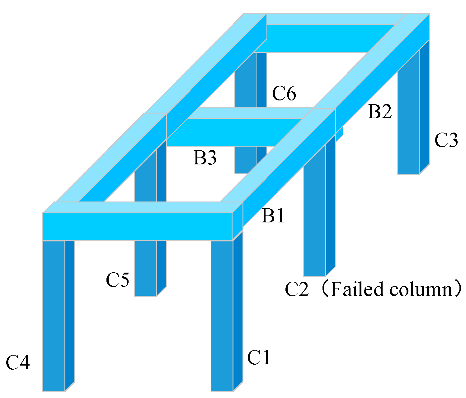
2.1. Progressive Collapse Mechanism

If the key components fail due to accidental factors, the RC frame structure will have the risk of progressive collapse. The single-story frame shown in Figure 1 is used to describe the possible collapse situation. If the C2 column fails due to accidental factors, the load R acting on the structure passes through the beam (or floor slab, for a frame with a floor slab) connected to the failed column and passes it to other columns (C1, C3, C4, C5, C6). If the bearing capacity reserve of the other columns is insufficient, the failure occurs in succession, and the structure collapses continuously. On the contrary, if the bearing capacity reserve of the other columns is enough to resist the consequence of internal force increase caused by the failure of column C2, but the beams (B1, B2, B3) connected with column C2 do not have enough bearing capacity and then fail, the structure will collapse.

2.1.1. Beam Mechanism

If the vertical load of the structure is transmitted from the frame beam (B1, B2, B3) to the adjacent frame column in the form of shear force, the resistance Rb of the structure to balance the vertical load R at this time comes from the shear resistance of the frame beam. The way to provide resistance is called the beam mechanism. Figure 2 briefly indicates the way in which the beam mechanism structure provides resistance. Then, according to the equilibrium conditions, the equilibrium equation in this state can be obtained:
R b = i V i = i M i 1 + M i 2 L i
In the formula, Vi is the beam end shear force of the ith beam; Li is the span of the i—root beam; Mi1, Mi2 are the bending moments at both ends of the ith beam.
Figure 2. Schematic diagram of beam mechanism.
Buildings 15 01525 g002
From the analysis of Formula (1), when the shear capacity provided by the beam is less than its flexural capacity, Rbu depends not on the shear capacity of the beam but, on the contrary, it depends on the flexural capacity of the beam. In the design of frame beams, the requirements of strong shear and weak bending should be met to avoid brittle progressive collapse caused by insufficient shear capacity. When the tensile steel bars at each beam end just yield and the plastic hinge is formed, the bending moment of the beam end section is the plastic hinge bending moment, and the resistance of the beam mechanism reaches the maximum:
R b u = i M i 1 p + M i 2 p L i
If RbuR, the deformation of the frame beam is gradually approaching stability, and the structure has the ability to resist progressive collapse.

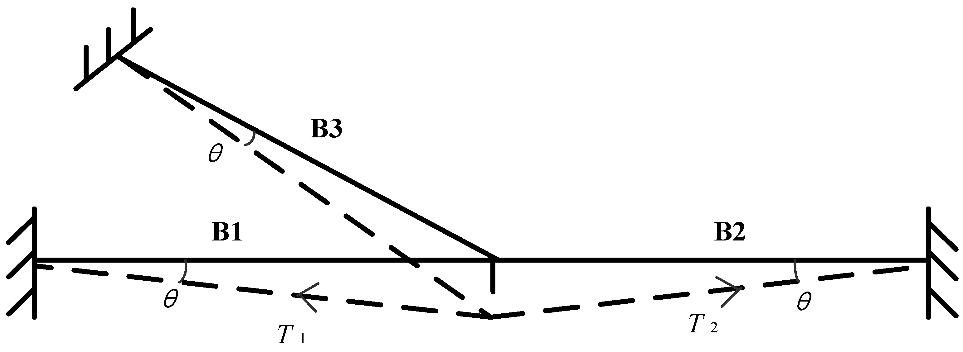
2.1.2. Catenary Mechanism

If RbuR, the frame beam will continue to deform. As the deformation increases, the concrete at the beam end gradually crushes, the plastic hinge fails, and the beam mechanism stops functioning. After that, only the catenary mechanism plays a role in resisting progressive collapse. Figure 3 briefly shows the way in which the catenary mechanism provides resistance.
The resistance Rc provided by the catenary mechanism can be solved by Equation (3).
R c = i T i sin θ i θ u < θ θ max
In the formula, θi is the angle of rotation of the beam end section of the frame beam (i.e., the angle of rotation); Tisin θi is the vertical component of the tension provided by the longitudinal reinforcement of the ith frame beam.
When the strain εs generated by the steel bar in the beam increases to the ultimate tensile strain εsu, the resistance provided by the catenary mechanism reaches the ultimate degree Rcu, and the rotation angle of the beam end θ = θmax.
R c u = i T i sin θ i max
If RcuR, the structure has the ability to resist collapse damage; if Rcu < R, the structure will collapse [23].
On the basis of statics, the dynamic term is added. From the perspective of the dynamic equation, the dynamic effect of the structure is considered, the inertial force and damping term are introduced, and the time history analysis or dynamic amplification factor is adopted. The expression relationship of the concrete beam effect is as follows:
E I 4 w ( x , t ) x 4 + c w ( x , t ) t + m 2 w ( x , t ) t 2 = p ( x , t )
Here, E I is the bending stiffness of the beam, E is the elastic modulus and the moment of inertia of the section; m = ρ A is mass per unit length (ρ is the material density, A is the cross-sectional area); c is the viscous damping coefficient; and p ( x , t ) is the dynamic distributed load.
The catenary equation of concrete considering dynamic effect is as follows:
μ 2 y ( x , t ) t 2 + c y ( x , t ) t = x T ( x , t ) y ( x , t ) x + q ( x , t )
Here, μ = ρ A is the linear density (ρ is the cable density, A is the cross-sectional area); T ( x , t ) = T 0 + E A ϵ ( x , t ) is the dynamic tension (T0 is the initial tension, ε is the strain); q ( x , t ) is the dynamic distributed load.
In addition, the dynamic amplification factor (DAF) and material degradation factor η ( t ) can be introduced to modify the material state equation of each stage.
The structure can be regarded as a collection of many components according to the specific connection mode, and the collapse of the structure as a whole can be regarded as the macroscopic embodiment of the behavior of the component group. In this sense, it becomes natural to study the system properties of the structure from the perspective of its components. A component in the structure has two roles. As a single component, the component should have sufficient local resistance to resist the effects of abnormal events; as a part of the structure, the failure of a key component, such as the bottom column, may lead to subsequent failure of other components or even the collapse of the entire structure. The demolition component method is a classical and standard method to study the collapse resistance of structures. This method evaluates the collapse resistance of structures by analyzing the influence of different components such as side columns, corner columns, and bottom inner columns on structural performance. It adopts some measures to remove the proposed failure components, analyzes the internal force redistribution of the structure under the original load, and gradually approaches the new stable equilibrium state or the progressive collapse failure. The application of this method covers theoretical analysis, numerical simulation, and experimental research.
In the Pushdown analysis, two vertical loading modes, full-span loading and damaged-span loading, are adopted. Among them, full-span loading refers to the uniform increase in the vertical load of the structure in each span. In the Pushdown analysis, the full-span loading and damaged-span loading modes can be used to obtain a basically consistent Pushdown curve. This shows that the influence range of structural damage caused by column failure is limited. Therefore, the difference between Pushdown analysis results under full-span loading mode and damaged-span loading mode can be ignored.

3. Design and Modeling of the Column Removal Scheme

The first floor of the building structure plays a vital role. As a bridge between the superstructure and the foundation, it not only bears all the loads from above, including live loads and snow loads, but also bears the influence of ground vibration (such as seismic force, vehicle and underground activities, or explosion shock waves) first. These factors make the bottom structural column a key part of the structure that needs special attention and consideration. At the same time, compared with natural disasters, the risk of human-made damage to building structures is greater. Historical terrorist attacks have shown that attackers often destroy the weak links at the bottom of buildings, and the consequences are often catastrophic. For example, car bomb attacks in the history of the United States show that once the bottom pillars are destroyed, the entire building may collapse in a short period of time, resulting in significant casualties. These observations highlight an urgent research topic: how to effectively assess the safety of the underlying structural columns and distinguish the collapse resistance of load-bearing columns at different locations. This is critical for the selective reinforcement of some key parts to improve the progressive collapse resistance of the structure.

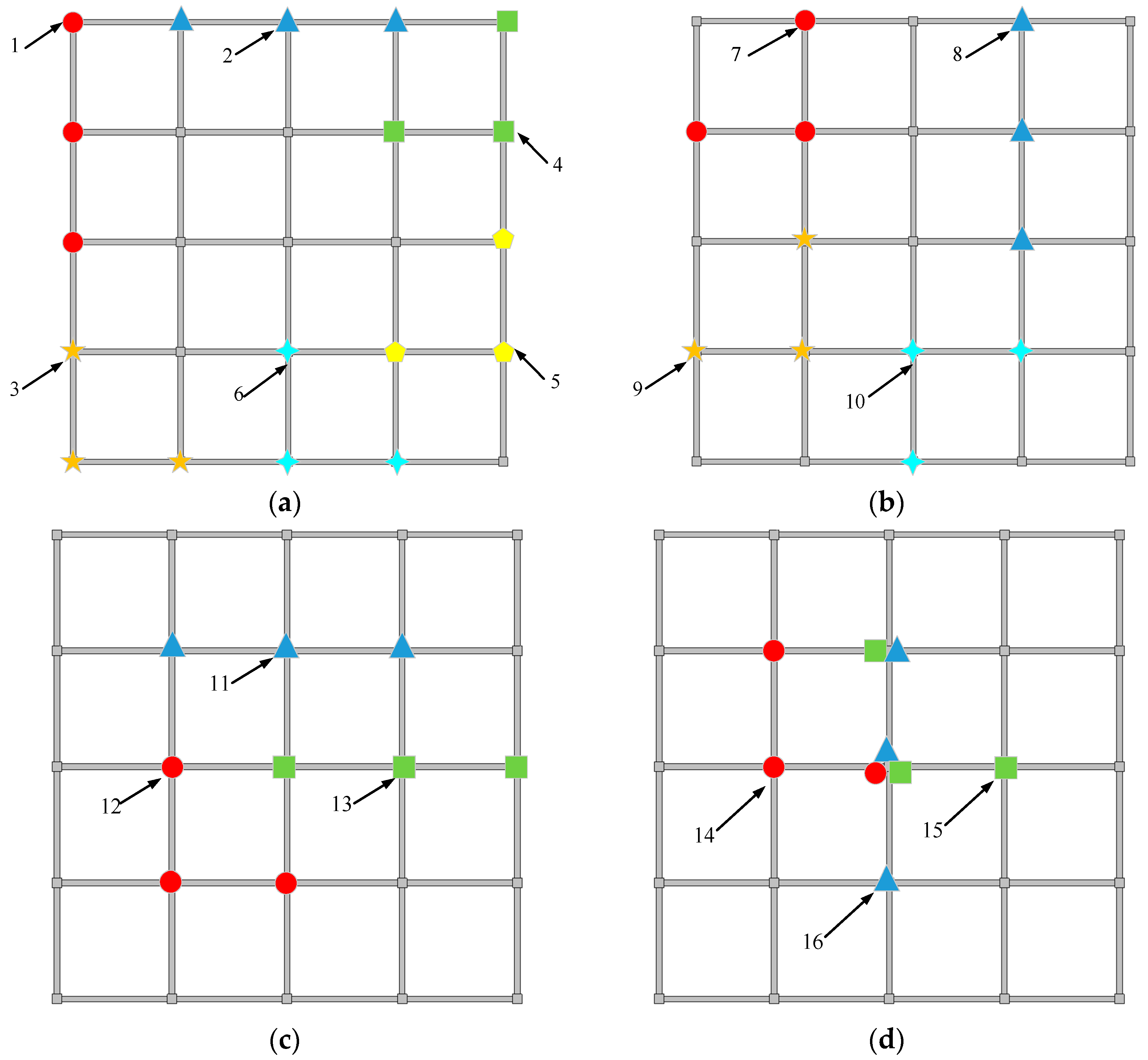
3.1. Design of the Single-Column Removal Scheme of Frame

Based on a simple reinforced concrete frame structure, a single-layer, five-bay, five-span frame structure model is established to analyze the collapse modes of a single column, two columns, and three columns. The resistance mode above the failure column, the collapse speed, and the influence on the remaining structure are the main concerns. Assuming that the columns are adjacent to each other when removing multiple columns, the designed frame structure is shown in Figure 4:
For the demolition in single-column mode, there are, in total, six working conditions, of which the outermost frame has three different types of columns; there are two different types of columns in the middle layer; there is one different type of columns in the innermost layer. The schematic diagram of the demolition condition is shown in Figure 5.

3.2. The Design of Double-Column Removal Scheme of Frame

For the demolition in the double-column mode, there are a total of six working conditions, of which two columns are in the outermost layer of the frame; there is one kind in the middle layer; there are two kinds of one column in the outer layer and one column in the middle layer. One column is in the innermost layer, and one column is in the middle layer. The schematic diagram of the working conditions of the demolition of the double columns is shown in Figure 6.

3.3. The Design of Three-Column Removal Scheme of Frame

For the demolition in the three-column mode, there are a total of 16 working conditions. In order to facilitate the expression, it is directly marked in the plane top view. According to the geometric type of the three-column arrangement, it can be divided into two categories: ‘-‘ and ‘L’. The expression forms of each type are shown in Figure 7.
By designing single-story frames with different numbers of demolitions, the anti-progressive-collapse mechanism of different residual structures can be further analyzed to obtain the importance of different columns to the whole structure and the influence on the robustness of the structure, which provides a theoretical basis for the dynamic response and anti-collapse analysis of multi-story frame structures. Based on this, the importance of each frame column and its accompanying progressive collapse range can also be obtained.

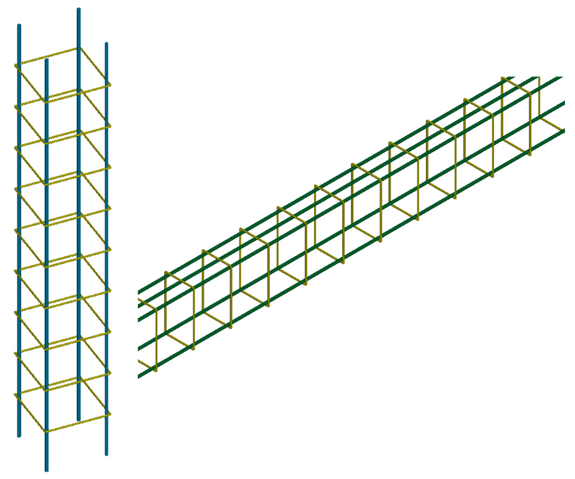
3.4. Model Establishment of the Framework

In order to verify the reliability of the numerical simulation under static loading conditions, ANSYS-APDL 18.2 software is used to establish the geometry. The reinforced concrete model is modeled by non-common node separation. This modeling method divides the concrete and steel bars into grids. The nodes at the same position are not the same, and the grids can overlap, which greatly reduces the difficulty of modeling. According to the design requirements, the building frame structure adopts a typical plane frame structure. The building structure is mainly composed of supporting beams and supporting column members. There are 25 supporting columns and 40 supporting beams. The transverse and longitudinal spans between columns are 3000 mm. The section size of the supporting beam is 250 mm × 150 mm, the section size of the supporting column is 250 mm × 250 mm, the diameters of the steel bars in the supporting beam and column are 10 mm and 12 mm, respectively, the diameter of the stirrup is 6 mm, the spacing of the stirrup is 150 mm, the thickness of the concrete protective layer of the supporting column and beam is 15 mm, and the geometric model of the supporting beam and column is as shown in Figure 8 and Figure 9.
As a slender structure, the steel bar adopts the Beam161 unit, and the concrete adopts the Solid164 solid unit. Because the building structure is composed of multiple regular hexahedrons, the shape is relatively simple. Therefore, this paper directly uses the automatic grid function in ANSYS APDL software to divide the grid of the building model. The grid shape is hexahedron. The unit grid size of the overall structure of the building is 0.1 m, the number of concrete frame grids is 441,600, and the number of steel grids is 57400. Because the building model adopts the non-common node separation modeling method, in order to simulate the interaction between steel bar and concrete, it needs to be defined by the keyword *CONSTRAINEDB_BEAM_IN_SOLID. In the constraint coupling relationship, the concrete is the main surface and the steel bar is the slave surface. Although this method has a large amount of calculation, it can truly reflect the mechanical properties of reinforced concrete materials.
The contact between the longitudinal reinforcement and the stirrup is surface-to-surface contact, which is realized by the keyword *AUTOMATIC_SURFACE_TO_SURFACE. The bottom of the building is fixed to the ground, and it is constrained by six degrees of freedom. Through the keyword *BOUNDARY_SPC_SET definition, the gravity loading in the vertical direction of the whole building is realized by LOAD_BODY_Z. Figure 10 is a schematic diagram of the numerical simulation of the structure.

3.5. Material Model

C35 concrete is selected, and the material model adopts the RHT model, which is more suitable for simulating the dynamic characteristics of concrete. The elastic limit surface, failure surface, and residual strength surface are used to describe the variations in yield strength, failure strength, and residual strength of concrete. At the same time, in order to simulate the crushing and spalling of concrete, it is necessary to define the failure criterion of concrete materials, and the minimum tensile strength of failure is set to 3.5 MPa through the *MAT_ADD_EROSION keyword. The failure stress is determined by Formula (7).
σ f a i l p , θ , ε = f s σ T X C p s R 3 ( θ ) F r a t e ε
In Formula (7), the failure surface equivalent stress strength σfail is an equation about the normalized pressure p*, the Rode angle θ, and the strain rate ε, where R3 (θ) is the Rode angle factor, p* = p/fc; σ T X C p s is the equivalent stress strength of the compression meridian of the quasi-static failure surface, and the quasi-static pressure ps = p/Frate (ε); Frate (ε) is the strain rate dynamic enhancement factor. fs is the shear strength.
R 3 ( θ ) = 2 1 Q 2 cos θ + ( 2 Q 1 ) 4 1 Q 2 cos 2 θ + 5 Q 2 4 Q 4 1 Q 2 cos 2 θ + 2 Q 1 2
Q = Q 0 + B p *
In Equation (8), Q is the tension–compression meridian ratio, Q0 is the initial Laya meridian ratio parameter, B is the Rode angle correlation coefficient, and θ is the Rode angle, 0 ≤ θ ≤ π/3.
σ T X C p s = p s f t / 3 f t f c Q + p s + f t / 3 f t / 3 f s f c R 3 S   H T L p s 0 p s f c / 3 f c / 3 f s f c R 3 S + p s f c / 3       0 < p s f s / 3 A ( p s * H T L * ) n                 p s > f s / 3
H T L = f t 3 f s / f c R 3 S f s / f c R 3 S f t f c Q
H T L * = 1 / 3 1 / A 1 / n
In Formula (9), A is the failure surface parameter, n is the failure surface index, R 3 S is the Rode factor under pure shear, ft is the uniaxial tensile strength, and fc is the uniaxial compressive strength.
F r a t e ε = ε ε 0 c β c                                     p f c / 3 p + f t / 3 f c / 3 + f t / 3 ε ε 0 c β c + p f t / 3 f c / 3 f t / 3 ε ε 0 c β t     f t / 3 < p < f c / 3 ε ε 0 t β t                                     p f t / 3
In Formula (10), ε 0 c = 30 × 10−6 s−1, ε 0 t = 3 × 10⁻⁶ s−1; β c is the compressive strain rate index, β c = 4 20 + 3 f c ; β t for the tensile strain rate index.
The failure stress of the elastic surface can be deduced from the equivalent stress of the failure surface, and the elastic polar stress is determined by Formula (9).
σ e l a s t i c p , θ , ε = f s σ T X C p s , e l R 3 ( θ ) F r a t e ε F e l a s t i c F c a p
In Equation (11), Felastic is the elastic scaling function; Fcap is the ‘cap’ function; and p s , e l is the quasi-static elastic limit pressure, p s , e l = p s / F e l a s t i c .
F e l a s t i c g c *                                   p f c , e l / 3 p + f t , e l / 3 f c , e l / 3 + f t , e l / 3 g c * + p f c , e l / 3 f t , e l / 3 f c , e l / 3 g t *   f t , e l < p < f c , e l / 3 g t *                                   p f t , e l / 3
In Formula (12), g c * is the compression yield surface parameter, g c * = f c , e l / f c ; f c , e l is the elastic limit stress of uniaxial compression; g t * is the tensile yield surface parameter g t * = f t , e l / f c ; f t , e l is the uniaxial tensile elastic limit stress.
F C A P = 1                   p f c , e l / 3 1 p p u p 0 p u 2         p u < p < p 0 0                   p f t , e l / 3
In Equation (13), p 0 = p e l is the pressure when the material pores begin to crush; p u is the uniaxial ultimate pressure.
The RHT model needs to be determined by many parameters. According to the above-mentioned material parameters, the basic strength parameters, failure surface parameters, and elastic limit surface parameters are shown in Table 1.
BEAM_IN_SOLID is a keyword used in LS-DYNA to realize the coupling of the beam element (steel bar) and solid element (concrete). Its function is to simulate the interactions between the steel bar and concrete. The principle is based on the embedded beam model, degree of freedom coupling, slip, and bond. NCOUP is an important parameter to control the coupling between the beam element and the solid element, and NCOUP = 2 is used for balancing accuracy and efficiency. CDIR = 1 controls the relative direction relationship between the local coordinate system of the beam element and the solid element and the axial direction of the local coordinate system of the beam (default along the axis direction of the beam element). AXFOR = 1 controls the axial force of the beam element to be transmitted to the solid element, enabling axial force coupling (transmitting a complete 6 degrees of freedom). PSSF = 1, penalty stiffness scale factor, is used to adjust the contact stiffness between the beam and the entity. XINT = 0 is the initial penetration offset, which is used to define the initial position deviation between the beam and the solid element.
The *MAT_PLASTIC_KINMATIC material model is selected for the reinforcement, which is related to the strain rate and takes into account the bilinearity of element failure. Different hardening methods are selected by changing the value of the hardening parameters. When β = 1, it is isotropic hardening; when β = 0, it is kinematic hardening; and when 0 < β < 1, it is mixed hardening. The material parameters are shown in Table 2. The yield stress of the material can be determined by Equation (14).
f y = 1 + ε d C 1 P σ 0 + β E P ε P
In Formula (14), f y is the yield stress of the steel bar; C and P are the strain rate parameters; β is the adjustment coefficient of the reinforcement model; σ0 is the initial yield stress of the steel bar; ε P is the effective plastic strain of the steel bar; Ep is the plastic hardening model of the steel bar.
Table 2. PLASTIC_KINMATIC material parameters.
Density/(g/cm3) Poisson’s Ratio Young’s Modulus /GPa Yield Stress/Gpa Tangent Modulus /Gpa Failure Strain
7.8 0.3 2000.4 1.92 0.15
Numerical analysis based on LS-DYNA 18.2 software has been applied in the field of building structures [27,28,29,30,31], including probabilistic assessment of progressive collapse resistance in RC slabs and the progressive collapse of steel structures under blast loading considering soil–structure interaction, etc. Considering the calculation efficiency and accuracy, the grid size is selected to be 2.5 cm. By comparing the progressive collapse response of the RC frame under the secondary edge column failure performed by DENG [18], the peak bearing capacity of the compressive arch of the frame structure in the experiment is compared. The numerical simulation working condition diagram is shown in Figure 11.
The three types of frames in the experiment were numerically calculated one by one. The final collapse comparison diagrams obtained according to the reinforced concrete structural parameters and reinforcement in the experiment are shown in Figure 12.
In Figure 12, the failure mode of the specimen is shown. Comparing the numerical and experimental results, it is found that there are serious cracks at the beam ends on both sides of the failure column, the lower longitudinal reinforcement is broken, and the upper concrete is crushed. Comparing the damage cloud diagram of the numerical simulation, the distribution characteristics of the compression and tension regions can be seen. There are serious wide cracks in the upper part of the beam end near the side column, and the concrete at the lower part of the beam end is peeled off, which corresponds to the damage cloud diagram of the concrete model. The blue area indicates that the concrete is basically intact. The concrete beam is deformed in a straight line, and multiple wide cracks appear in the outer side column. The main damage in the third group of specimens is also concentrated at the beam end. The steel bar at the lower part of the beam end on the right side of the failure column is broken, and the upper concrete is crushed. Dense cracks appear near the end of the side column beam, but the damage area of concrete decreases. The overall deformation of the beam is curved, and multiple bending cracks appear on the outer side column. The failure mode of the first group is similar to that of the second group. However, due to the small section size of the column, more serious damage occurs to the outer side column. Wide, long cracks are formed in the joint area, and many small bending cracks appear at the same time. In the small deformation stage, a few bending cracks are produced in the outer side column. With the increase in displacement, the main crack in the outer side column begins to form due to the tension generated by the steel bar at the beam end. When the upper steel bar is broken, the tension generated by the lower steel bar makes the crack develop rapidly.
Through the above analysis, it can be seen that the final collapse and material failure results of the structure are highly consistent. On the basis of the experiment, the theoretical calculation model is compared. YU et al. [32] and LU et al. [33] proposed the prediction formula of the peak bearing capacity of the arch and the calculation model of the bearing capacity of the pressure arch. Based on the numerical simulation of the three groups of specimens in the DENG experiment, the peak bearing capacities of the pressure arch are 48 kN, 54 kN, and 44 kN, respectively. The theoretical calculation model prediction results proposed by YU et al. are 40 kN, 47 kN, and 38 kN, respectively, and the error range is 15%~20%. The prediction results of the calculation model proposed by LU et al. are 52 kN, 59 kN, and 50 kN, respectively, and the errors are 8%~12%. The results of the numerical simulation and the experimental and theoretical calculations are shown in Figure 13.
Through the above model verification, it can be seen that the numerical model used in this paper has high credibility. Following the basic law of the collapse process of concrete frame structures, it can support the next numerical simulation research.

4. Research on Multi-Column Demolition of Four-Plane Frame Structure

From the resistance and failure mode of concrete substructures, it can be seen that there are great differences in the dynamic response and collapse process of various substructures after column failure. However, the overall response of the structure under constraints cannot be seen only through simple concrete substructures. Moreover, there is a gap in the surrounding stiffness environment at different column removal positions, which will greatly affect the overall dynamic response of the structure and will further affect the continuous collapse mode and resistance contribution. In order to clarify the influence of each column removal mode on the overall structure during the progressive collapse process, parameters such as the displacement/span of the failed column joints and the XY horizontal displacement of the remaining structural columns were studied.
Because of the large number of columns, all columns are now numbered for distinction. The numbering method is shown in Figure 14.

4.1. Study on Single-Column Demolition Mode

4.1.1. Failure Column Stress and Vertical Displacement Analysis

Figure 15 shows the variation in stress above the failed column with displacement under the condition of single-column dismantling.
In the elastic stage, the overall stiffness matrix remains constant, the stress distribution follows the linear elastic relationship, and the stress and strain at the failure position increase synchronously. When the single column at different positions fails, the stress transfer is first carried out on the beam connected to it, resulting in a difference in the bearing level of the beam effect stage. In the initial elastic stage, the linear stress distribution is in the linear elastic range. At this time, the stress distribution follows the elastic theory, corresponding to the part of the linear growth of the stress.
As the stress increases, the local stress concentration of the concrete beam (such as the beam end or the mid-span node) in these areas is first close to the material strength, but it has not yet triggered plastic deformation. With the beginning of the plastic stage, the internal force path begins to reconstruct, and the continuous increase in the load leads to the yield of the concrete material. When the section stress reaches the yield strength, the area enters the plastic stiffness drop. At this time, the strain growth rate begins to become faster, and the local softening effect leads to a sudden drop in the stiffness of the failure area, forming a ‘strain absorption zone’. The surrounding strain is concentrated in this area and accelerates damage accumulation. When reinforced concrete beams are subjected to bending, the stiffness of the mid-span section decreases due to concrete cracking, resulting in strain concentration.
Local damage (such as concrete cracking and steel yielding) in the stiffness degradation stage leads to the degradation of the sub-stiffness matrix and the redistribution of internal forces. The stress growth at the failure position stagnates (entering the plastic platform), but the strain continues to accumulate, and the stress in the adjacent area is forced to increase. In the stress redistribution stage, the stress at the failure position stagnates, the strain continues to grow, and the stress in the adjacent area is forced to increase to balance the external load. At this time, the plastic hinge of the beam is formed, and the bending moment above the failure column is transferred from the mid-span to the support, forming an ‘internal force arch’.
With the gradual failure of the pressure arch effect, the catenary effect begins to occur, and the axial tension of the beam gradually dominates the force transmission path. At this time, the steel bar and the concrete are subjected to synergistic force, and the stress is linearly distributed along the section height. The stress at the failure position (mid-span bottom) is close to the peak value, and the strain is increasing. With the increase in strain, the steel bar in the middle of the span yields, and the strain increases rapidly to the starting point of hardening. The steel bar enters the hardening stage, and the strain continues to grow to the ultimate strain. The compressive strain of concrete in the compression zone exceeds the peak strain, enters the softening stage, and the stress is redistributed to the adjacent section. In the failure stage, the steel bar breaks, and the section completely loses bearing capacity. The reaction of the stress–strain evolution proceeds to stiffness at the failure column position, and the accumulation of plastic strain leads to stiffness degradation. The steel bar yields. When the strain of the steel bar increases, the elastic modulus decreases to the tangent modulus, and the bending stiffness of the section decreases. After the concrete is crushed and the concrete strain reaches peak strain in the compression zone, the softening behavior causes the compression stiffness to become negative, further weakening the overall stiffness, and the load is transferred to the adjacent area, triggering a chain failure.
Figure 15 compares the effective stress–displacement curves of six working conditions. With the decrease in the distance from the center of the structure, the vertical displacement of the failed column decreases rapidly from 300 cm to 1.6 cm. The different positions of the six demolition columns lead to different changes in the bearing capacity of the remaining frame structure to the field force load. For the six different positions of removing columns, the main difference is that there are differences in the number of suspended beams bearing them. The number of bearing beams of the six structures is 2, 3, 3, 4, 4, and 4, respectively. As a result, there is not enough of an alternate bearing capacity transfer path to effectively support the load of the failure column in case No. 1, which eventually collapsed significantly. It can be seen that the corner column has a poor bearing level in the event of progressive collapse. For cases 2 and 3, 4 and 5, and 6, with the same number of load-bearing paths, we will compare and analyze the two groups: for 2 and 3, the load transfer paths follow the same three beams, in which a symmetrical pair of beams can achieve the resistance mode of beam effect and catenary effect, and the other beam can achieve a small cantilever beam resistance but can have only a small beam effect. The main difference between the two is the position of the beam where the force transfer path is located. Because the stiffness of the side near the center and the remaining complete structure is strong, and the stiffness of the relatively independent and close to the outside structure is weak, the anti-bearing level of the number 2 side is poor, leading to a larger vertical displacement. For cases 4, 5, and 6, there are four force transmission paths, and the two–two symmetry can have an effective resistance effect. Therefore, the vertical displacement gap between the three is small and can be basically regarded as the same, but the stiffness effect of the remaining structure still has a greater impact, that is, the closer the failure column is to the center of the structure, the smaller the vertical displacement is.
By comparing the six working conditions in the figure, it can be found that except for 1, the other five groups did not reach the peak stress. With the increase in the force transmission path and the failure column closer to the center of the structural stiffness, the effective stress gradually decreased and approached the fixed value. It can be seen that the remaining structure can still resist the large gravity load.
With the continuous increase in linear load, the structure will have an irreversible collapse trend. The end point tangent slope and the maximum deflection span of each working condition gradually decrease as the position coordinates of the failure column are closer to the center of the structural stiffness, showing more regular characteristics.
The beam effect of the cantilever beam plays a major role in the loading process. In the later stage of the loading process, the effect of the steel bar begins to be obvious; it provides a certain traction force, but the effect is not significant enough. In working condition 2, due to the large deformation deflection of the concrete beam, the catenary mechanism provides a large resistance after the end of the beam effect. However, due to the existence of concrete columns (corner columns) with low stiffness, with the increase in load, it leads to the occurrence of pull-type progressive collapse. The beam effect and catenary action provided by working condition 3 are more obvious, and the average on both sides makes it bear a larger resistance. The maximum displacement values of working condition 3 and working condition 2 are more than five times. The change gap between 4, 5, and 6 is small, which shows that the influence of a single column failure on the internal column of the structure is very limited.

4.1.2. Horizontal XY Displacement of Column Apex (Single-Column)

Figure 16 shows the variation in horizontal displacement of the remaining column over time under the condition of single-column dismantling.
The change in the horizontal displacement near the failure column is the result of the joint action of internal force redistribution and material damage, which is manifested in the reconstruction of the internal force path caused by load transfer and the nonlinear growth of stress and strain in adjacent members. Stiffness degradation and material nonlinear coupling lead to accelerated displacement accumulation. Local damage and overall instability promote each other. When a column fails, the vertical load originally borne by it needs to be redistributed through the adjacent members. At this time, the beam near the failure column will bear additional tension/pressure due to the catenary effect or arch effect, resulting in a significant change in internal force. The concrete is compressed to form a pressure arch, which transmits the load to the adjacent support and causes the axial compression ratio of the adjacent column to increase. The beam transmits the load through the axial tension, resulting in a decrease in the bending moment at the beam end, but the axial force increases significantly. With the initial growth of the horizontal displacement, after the support of the failure column disappears, the local stiffness drops sharply, and the horizontal constraint of the adjacent area is weakened. The lateral displacement causes the floor or beam above the failure column to deviate horizontally due to the loss of lateral support. The inter-story displacement angle of the floor where the failure column is located exceeds the specification limit, triggering the destruction of the surrounding structural members.
The key role of the beam–column joint leads to a sudden increase in the shear stress of the joint. The shear force at the beam end above the failed column needs to be transmitted to the adjacent column through the joint. The shear stress in the core area of the joint may exceed the shear strength of the concrete, resulting in oblique crack propagation. The response of adjacent columns leads to the increase in the axial compression ratio, and the adjacent columns need to share the axial force of the failure column. The axial compression ratio exceeds the limit value, which causes concrete crushing or longitudinal steel bar buckling, and thus, concrete damage and crack propagation. Cracks are generated at the bottom of the floor near the failure column due to the negative bending moment. The concrete in the compression zone of adjacent columns with compression damage enters the softening stage. The strain exceeds the peak strain, the damage factor accumulates, and the stiffness decreases. The plastic strain in the steel bar accumulates, the longitudinal reinforcement of the beam yields, and the strain in the longitudinal reinforcement of the beam quickly reaches the yield strain under the catenary effect.
The displacement time history curve is characterized by the fact that the horizontal displacement at the moment of failure increases with the increase in stress, and the amplitude is closely related to the location of the failure column. The spatial distribution of displacement is around the failure column. If the failure column is located at the edge of the structure, it may cause the overturning trend of the surrounding structure. If the stiffness condition of the surrounding structure is weak and cannot resist the overturning moment, it will cause the surrounding components to collapse continuously.
In the above process, due to the difference in connection conditions, the beam effect and catenary effect, which dominate the internal force redistribution process, have significantly different stress changes in the surrounding adjacent structures. For the outer residual structure with fewer force transmission paths and lower stiffness, it is more likely to produce a progressive collapse trend. However, when the stiffness condition of the surrounding structure is strong, such as the uniform distribution of the surrounding stiffness or in the center, it is not enough to be affected by the horizontal displacement to make the surrounding components overturn, but at this time, the catenary effect and the beam effect have been brought into play until the connected components fail, which cannot further cause the horizontal response and does not cause significant plastic changes or damage to the surrounding components, so that the horizontal displacement increases to the maximum and then decreases slightly.
Figure 16 shows the horizontal displacement of the remaining column after removing the failure column under six working conditions. It can be seen that the influence of single column failure on the whole structure is relatively small. It mainly has a pulling effect on the adjacent columns around the failure column. Except for the large horizontal displacement of the adjacent columns in the two working conditions, the other working conditions do not produce the horizontal displacement that causes the failure of the surrounding columns. It can be seen that the dynamic response of the single column failure in the whole structure is small, which basically obeys the stiffness relationship between the associated columns.
It can be seen from the observation of working conditions 4, 5, and 6 that the horizontal displacement of some adjacent columns increases first and then decreases. In the small deformation stage, the surrounding columns first move outward. When the vertical displacement is about 150 mm, the lateral displacement of the side column reaches the maximum. As the displacement further increases, the side column gradually moves to the inside. Due to the lack of horizontal constraints, the maximum lateral displacement of the outer side column is much larger than that of the inner side column, and the maximum lateral displacement of the outer side column appears at the height of the beam axis.
In addition, as the failure column is far away from the center of the structure, its stiffness decreases, resulting in a smaller joint response and resistance of the surrounding column. This makes it more prone to separation and collapse, which can be seen from the maximum horizontal displacement of 0.06 cm in condition 1, which is smaller than in the other conditions. It can be seen that the position of the failure column has a great influence on the overall horizontal displacement of the structure and leads to different influence ranges.
It can be seen that the dynamic response process and law of the structure are obvious; they are mainly affected by the number of directly pulled beams and columns and the stiffness between the surrounding, directly related columns. A large number of associated columns but low strength will still cause a large local dynamic response, while a small number but high strength will respond quickly and may cause continuous collapse of the surrounding structure.

4.1.3. Response Range Analysis and Collapse Analysis Based on Single-Column Demolition Conditions

Figure 17 shows the relationship between the deflection span value above the failure column and the distance between the failure column and the center of the structure.
As the distance gradually increases, the displacement above the failure column also gradually increases, but the overall function shows an inverse proportional function relationship and a rare exponential function relationship. There is a significant inflection point in the process of the failure column gradually away from the center of the structure, which makes the vertical displacement or deflection suddenly larger. Figure 18 shows the relationship between the mean horizontal displacement of the remaining structural columns and the center distance of the structure under different column removal conditions.
With the increase in the distance from the center of the structure, the horizontal displacement of the structure first increases and then decreases, which is directly related to the position of each structural column. The column with weak stiffness connection will become the primary target of the structural response. It can be seen from this that in order to have a larger-scale structural dynamic response and its associated collapse effect, the initial collapse needs to occur far away from the stiffness center but not at the farthest end.

4.2. Study of the Demolition Mode of Double Columns

For the demolition of the double-column mode, there are a total of six kinds of working conditions, of which two columns are in the outermost layer of the frame; there is one kind in the middle layer; there are two kinds of one column in the outer layer and one column in the middle layer; one column is in the innermost layer; and one column is in the middle layer.

4.2.1. Substructure Resistance (Double Columns)

Figure 19 compares the effective stress–displacement curves of the six working conditions.
As the position of the column is closer to the center of the structure, the vertical displacement of the failed column decreases rapidly, from 300 cm to 6 cm, and the stress of the double-column demolition condition is more regular than that of the single-column demolition condition. As the stiffness center is near the structure, the maximum stress value of the failure column decreases, which shows that the structural system can bear greater stress.
Comparing the six working conditions, it can be clearly observed that the maximum vertical displacement difference between the two columns gradually decreases in the case of double column failure, but the gap between the two columns shows a great change. In the initial stage of stress loading, the stress evolution process of the two failure columns is similar. With the increase in loading, the stress between the failure columns begins to differ. Even for the regular frame structure, the resistance provided by the residual structure at different positions and stiffness is still quite different.
The numbers of load-bearing beams in the six structures are 3, 4, 5, 5, 6, and 6. It can be seen that there is a significant relationship between the number of transfer paths of the spare bearing beam and the resistance of the structure, but the location type of the failure column will cause certain changes in the bearing process. Even if the number of alternate bearing paths is similar, there is still a gap in the stiffness of the concrete column connected by the bearing beam. For cases 3 and 4 and 5 and 6, which have the same number of load paths, we will compare and analyze the two groups: For 3 and 4, which are the load transfer paths of five beams, 4 has symmetrical stiffness on both sides and 3 has a stiffness weak side, so the stress changes between the two failure columns are also similar, while the stress change process of the two columns in 3 is not uniform, which leads to the smaller resistance provided by the two columns. Comparing 5 and 6, as mentioned above, there is the same symmetry gap, resulting in six working conditions with better symmetry that can resist greater stress.
By comparing the six working conditions in the figure, it can be found that except for condition 1, the other five groups did not reach the peak stress. With the increase in the force transmission path and the failure column closer to the center of the structural stiffness, the effective stress gradually decreased and approached the fixed value. It can be seen that the remaining structure can still resist the larger gravity load.
Except for working condition 1, the rest have obvious catenary effects, and obvious collapse occurs in working conditions 1, 2, and 3. It can be seen that the double-column demolition mode has a great influence on the collapse. The symmetrical residual structure in 4 and the internal damaged structures in 5 and 6 can resist the impact of collapse to a certain extent. It can be seen that the significant effect provided by the beam effect is greatly related to the structural stiffness and symmetry. The failure of the double columns will bring possible progressive collapse events to the corner columns and side columns, but the failure of the double columns has a very limited impact on the internal columns of the structure and cannot cause effective impact.

4.2.2. Horizontal XY Displacement of Column Apex (Double Columns)

Figure 20 shows the horizontal displacement of the remaining columns that remove the failed columns under six working conditions, and the number of remaining columns that remove the failed columns is 23.
It can be seen that the influence of double column failure on the whole structure is significantly greater than that of single column failure. The obvious horizontal traction displacement occurs in condition 2 and condition 3, but the number of columns in condition 2 and condition 3 is small. Although the displacement in condition 5 is almost 1 cm, it is difficult to cause the final horizontal traction response because the number of columns in the response is 3.
From the comparative observation of working conditions 1 to 6, it can be seen that there is no significant regularity in the maximum lateral displacement response, which is greatly related to the stiffness condition of the failure column. In case 1, the failure column can provide support for the beam effect only above the cantilever structure, and the bending moment provided by the beam effect is limited, which cannot provide horizontal traction for the surrounding intact structural columns, and the dynamic response to the remaining structure is small. There is a unilateral low-stiffness structure in conditions 2 and 3, which causes the subsequent progressive collapse, but the horizontal displacement value in condition 3 is much smaller than that in condition 2.
It can be seen from the observation of working conditions 4 and 5 that the horizontal displacement of some adjacent columns increases first and then decreases. In the small deformation stage, the surrounding column first moves outward. When the time is about 900 ms, the lateral displacement of the side column reaches the maximum. With the further increase in the displacement, the side column gradually moves inward. Due to horizontal constraints and insufficient stiffness, the maximum inward displacement of the outer side column is much larger than that of the inner side column. It can be seen that the maximum lateral displacement of the adjacent columns under the above two conditions is greater than that of the specimen NSP. The main reason is that the seismic design specimen SP has a greater tensile force on the outer side column due to the increase in the reinforcement ratio of the beam and the late fracture of the steel bar. However, due to the small size of the side column, the specimen NSP-S will produce greater deformation under the action of horizontal tension. For the specimen NSP-S, when the vertical displacement is 500 mm, the lateral displacement reaches the maximum, and at the final stage of loading, the lateral displacement of the side column is retracted, mainly because the horizontal reaction force is obviously reduced after the fracture of the top steel bar of the left span beam.
In addition, as the failed double columns are away from the center of the structure, their stiffness is reduced, resulting in less joint response and resistance of the surrounding columns. This makes it more prone to separation and collapse, which can be seen from the maximum horizontal displacement of working conditions 1, 2, and 3. It can be seen that the position of the failure column has a great influence on the overall horizontal displacement of the structure, and it leads to different influence areas and dynamic response processes.
It can be seen that the dynamic response of the structure under the condition of double columns is mainly affected by the number of directly pulled beams and columns and the stiffness between the surrounding, directly related columns. A large number of associated columns but low strength will cause a large local dynamic response, while a small number but high strength will quickly collapse and may cause impact on surrounding low-stiffness structures.

4.2.3. Response Range Analysis and Collapse Analysis Based on Double-Column Demolition Conditions

Figure 21 shows the relationship between the deflection span value above the failure column and the distance between the failure column and the center of the structure.
As the distance increases, the displacement above the failure column gradually increases, and it reaches the maximum at a distance of 25.42 m. It can be seen that the collapse displacement value is the largest when both failure columns are the outermost. Although working condition 5 is at the center of the structure compared with working condition 4, it is obvious that the stiffness distribution of the surrounding structure of working condition 4 is uniform and large, and the upper side stiffness of working condition 5 is low, resulting in the increase in the deflection span value. The overall function still shows an inverse proportional function relationship. There is a significant inflection point in the process of the failure column gradually away from the center of the structure, which makes the vertical displacement or deflection suddenly larger, but the situation becomes more complicated than the single-column failure. Figure 22 shows the relationship between the mean horizontal displacement of the remaining structural columns and the center distance of the structure under different column removal conditions.
With the increase in the distance from the center of the structure, the horizontal displacement of the structure increases first and then decreases, which is similar to the conclusion obtained with single-column demolition. However, the dynamic response caused by the double columns is significantly larger, about an order of magnitude larger than the horizontal displacement caused by the single column, indicating that the stiffness of the structure will be greatly weakened with the increase in the number of demolition columns, which may cause a greater trend of progressive collapse.

4.3. Study of Three-Column Demolition Mode

For the removal of the three-column mode, there are a total of six working conditions, of which two columns are in the outermost layer of the frame; there is one kind in the middle layer; there are two kinds of one column in the outer layer and one column in the middle layer. One column is in the innermost layer, and one column is in the middle layer.

4.3.1. Substructure Resistance (Three-Columns)

Figure 23 compares the effective stress–displacement curves of 16 working conditions.
With the decrease in the distance of the demolition column from the center of the structure, the vertical displacement of the failed column decreases rapidly from 900 cm to 25 cm. It can be seen that the proportion of structural collapse caused by the three-column demolition condition increases significantly. The single-column demolition is 1/6, the double-column demolition is 2/6, and the three-column demolition greater than 100 cm reaches 10/16. The collapse mode of the three-column demolition condition presents greater complexity and irregularity, which is mainly caused by the diversity of the column removal methods, reflecting the high variability and uncertainty of the actual situation.
Comparing the 16 working conditions, it can be clearly observed that the stress change trend between the three failure columns increases to a certain high point first, and then gradually increases to the next peak after a continuous small decrease or steady change. There is also a significant law between the failure columns in each working condition: if the connection between the three columns is close, the vertical displacement difference in the collapse process is small, so that the stress change trend between the three failure columns is relatively close, and in the later stage of most working conditions, the collapse begins to separate, resulting in a large change in the stress between the three columns.
The number of load-bearing beams of the 16 structures is 4, 5, 4, 5, 6, 6, 6, 7, 7, 8, 8, 7, 8, and 8. It can be seen that there is a significant relationship between the number of transfer paths of the spare bearing beam and the resistance of the structure. When the number of three-column demolition is less than 8, there is a greater possibility of collapse. For 5 and 6 and 7, 8 and 9 and 10 and 13 with the same number of bearing paths, the stress and vertical displacement are different depending on the structural geometry of the three columns and the stiffness conditions of the columns.
By comparing the 16 working conditions in the figure, it can be found that almost all groups reach the peak stress. With the increase in the force transmission path and the closer the failure column is to the center of the structural stiffness, the effective stress gradually decreases and approaches the fixed value. It can be seen that the remaining structure can still resist the larger gravity load, but there will be a tendency to collapse.
In addition to the conditions 1, 3, and 4, the rest have obvious catenary effects, and obvious collapse occurs in conditions 1–10. Compared with the double-column demolition mode, the area and scale of collapse become larger. For the multi-column demolition mode with more than three columns, it will be more affected by the stiffness of the adjacent columns. The failure of three columns will bring possible progressive collapse events to the failure columns of peripheral structures such as corner columns and side columns, but the influence on the failure columns inside the structure is relatively small, and it can still resist large loads.

4.3.2. Horizontal XY Displacement of Column Apex (Three-Columns)

Figure 24 shows the horizontal displacement of the remaining columns that remove the failed columns under 16 working conditions, and the number of remaining columns that remove the failed columns is 22.
It can be seen that the influence of double three-column failure on the overall structure is significantly greater than that of single-column and double-column failure. The obvious horizontal traction displacement occurs in condition 2 and conditions 4 to 12. The numbers of horizontal responses of the column in the above conditions are 2, 1, 2, 1, 1, 3, 3, 3, 3, 3, 4, and 3. As the failure column gradually approaches the stiffness center, the horizontal displacement value gradually decreases, and the maximum displacement value generally does not exceed 120 cm.
From the comparative observation of working conditions 1 to 16, it can be seen that there is no significant regularity in the maximum lateral displacement response, indicating that there is a large uncertainty in the structural response caused by multi-column failure. There are corresponding numbers of low-stiffness structures around the failure columns in conditions 2, 4, 5, 6, and 7, resulting in large horizontal responses of these structures. The horizontal dynamic pulling columns in the above conditions are all side columns or corner columns of the structure. It can be seen that the peripheral columns of the structure have great potential safety hazard in large-scale progressive collapse events.
It can be seen from the observation of working conditions 13, 15, and 16 that the horizontal displacement of some adjacent columns increases first and then decreases. In the small deformation stage, the surrounding column first moves outward. When the time is about 900 ms, the lateral displacement of the side column reaches the maximum. With the further increase in the displacement, the side column gradually moves inward. Due to horizontal constraints and insufficient stiffness, the maximum inward displacement of the outer side column is much larger than that of the inner side column. In addition, as the failed double columns are far away from the center of the structure, their stiffness decreases, resulting in a smaller joint response and resistance of the surrounding columns to them, making them more prone to separation and collapse. In case 1 and case 3, only the collapse and rapid response of the failed column exist, and the connection condition of the remaining structure around them is weak, which makes the failure effective only for itself.
It can be seen that the dynamic response of the structure under the condition of three columns is mainly affected by the number of directly pulled beams and columns and the stiffness between the surrounding, directly related columns. The main influence range of progressive collapse is the outer column of the structure. The large number of associated columns but low strength will cause a local, large dynamic response. The small number but high strength will collapse rapidly, and it may cause impact on the surrounding low-stiffness structure.
For the layout type in the three-column demolition mode, the obvious difference between the ‘-’ and ‘L’ layouts is reflected in the concentration degree of the three-column failure. Obviously, the ‘L’ type layout will make the failure column group more concentrated, and the ‘-’ type layout is looser. Among them, there are 10 groups of ‘L’ type layout, and the numbers of ‘L’ type connecting adjacent complete columns with higher concentration are 3, 4, 5, 5, 5, 5, 6, 6, 6, 7, 7, 7, and 7, respectively. There are six groups of ‘-’ type layout, and the numbers of adjacent complete columns are 4, 5, 7, 8, 7, and 8. The number of connecting adjacent columns will provide more bending moment transmission paths during the beam effect and provide more axial force transmission paths when the catenary plays a role to resist the damage of the horizontal structural response. The residual structure of the ‘L’ type layout with a stronger concentrated area can provide fewer force-transmission paths, resulting in a more obvious direct collapse area. The dispersed failure column group will provide more resistance paths before the occurrence of irreversible collapse, thus effectively reducing the evolution of the collapse process. As the failure area approaches the center, the difference between the two layouts will be more obvious.

4.3.3. Response Range Analysis and Collapse Analysis Based on Three-Column Demolition Conditions

Figure 25 shows the relationship between the deflection span value above the column and the distance between the failure column and the center of the structure under the three-column failure condition.
As the distance increases, the displacement above the failure column also increases gradually. Due to the increase in data volume and the complexity of column removal conditions, it can be seen that there is a certain error in the change in deflection span value, but the whole still presents an exponential function form about e, and the fitting degree is high. As it gradually moves away from the center of the structure, it reaches a value of 1 when the distance is about 3.5 m. It can be seen that the removal of the three columns has the greatest impact on the structure.
Figure 26 shows the relationship between the mean horizontal displacement of the remaining structural columns and the center distance of the structure under different column removal conditions.
With the increase in the distance from the center of the structure, the horizontal displacement of the structure increases first and then decreases. This is the same as the conclusion of single-column demolition and double-column demolition. The outer column of the structure with weak stiffness connection will become the primary target of structural collapse, and it is difficult to have an impact on the surrounding structural columns with strong stiffness. From the perspective of the overall change trend, as the failure column gradually moves away from the center of the structure, the horizontal displacement caused by it increases slowly and then increases linearly, reaching a peak at 35–40 m and then decreasing rapidly.

5. Conclusions

As one of the common types of building structures, the safety and collapse resistance of frame structures under dangerous conditions have attracted more and more attention. In this paper, the single-story simple frame structure is taken as the research target, and the collapse mode of the building under the condition of removing a single column, removing two columns, and removing three columns is analyzed by high-precision modeling. By studying the collapse process of buildings with different demolition positions, the parameters such as the collapse speed of the frame structure, the stress above the failure column, and the horizontal displacement of the remaining structure are analyzed, and the influence of different demolition positions of the concrete column on the remaining structure is obtained. Based on the above rules, it is found that there is a significant relationship between the coordinates of the failure column relative to the center of the structure and the overall collapse resistance and overall structural response of the structure. The main conclusions of this paper are as follows:
(1)
With the increase in the number of demolished columns, the collapse resistance of the structure decreases significantly. The column removal position affects the remaining structure by affecting the number of transfer paths of the backup bearing beam. For the demolition column mode with the same number of bearing paths, it depends on the geometric form of the remaining structure and the stiffness condition of the column. Different demolition column modes show different stresses and vertical displacements.
(2)
The smaller the difference between the stiffness and location conditions between the failure columns, the closer the collapse process of each failure column and the more average the collapse speed. With the increase in the number of demolished columns, the displacement and velocity of progressive collapse caused by corner columns will be greater. For the multi-column demolition mode, it will be more affected by the stiffness of the adjacent columns. The failure of three columns will bring possible progressive collapse events to the failure columns of peripheral structures such as corner columns and side columns, but the influence on the failure columns inside the structure is relatively small, and it can still resist large loads.
(3)
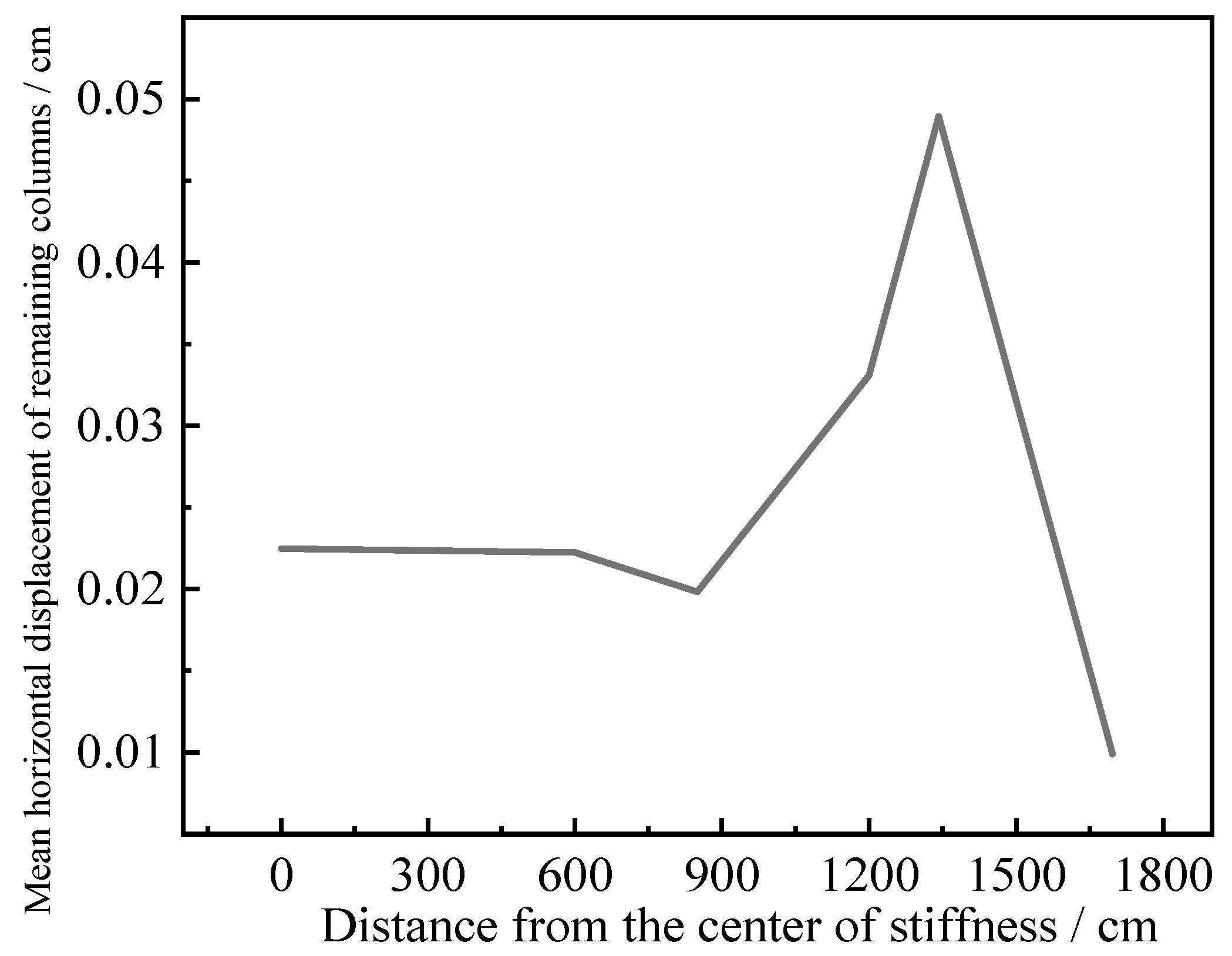
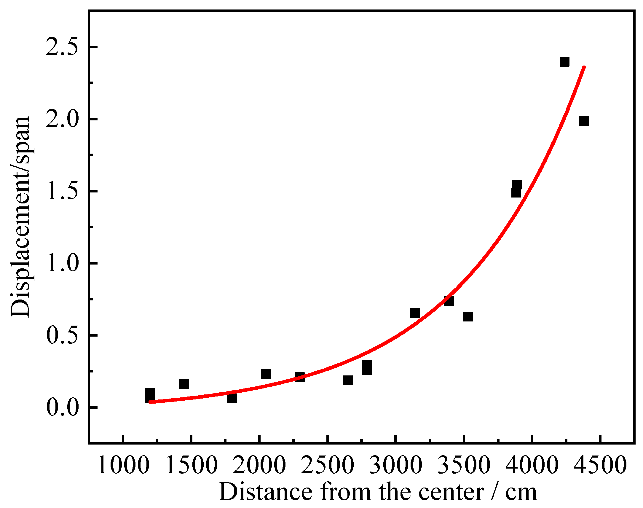
With the increase in the distance between the failure column and the center of the structure, the horizontal displacement of the structure shows a trend of increasing first and then decreasing. The conclusion of single-column demolition and double-column demolition is the same. The outer column of the structure with weak stiffness connection will become the primary goal of the collapse of the structure, and it is difficult to have an impact on the structural column with strong stiffness.
The load characteristics and failure characteristics under extreme load conditions such as explosion lead to the failure of local adjacent multi-columns, which shows that the weakest position of the dynamic response of the structure under the condition of multi-column failure will appear at the secondary edge of the structure. The strength, load path, and bearing capacity design (beam) of the secondary edge structure should be strengthened.
The load is dispersed by the multi-path force transmission system to avoid the chain reaction caused by single-point failure. The plastic deformation of materials is used to absorb energy and delay the collapse process. Strengthen the key components and joints in this area and improve the local resistance to extreme loads. In terms of the multi-path load transfer system, transfer trusses or ring beams are set up: steel trusses or concrete ring beams are arranged on key floors to form a closed force-transmission loop. Column reinforcement and joint enhancement are carried out in terms of key components and joint reinforcement.
For the failure of adjacent column groups the local catenary mechanism is added, the strengthening beam is set above the failure column area, and the failure area is crossed by the tensile catenary action. Cross steel braces or V-shaped braces are added to transfer the load to the non-failure column.
Supports are added to the secondary edge columns to improve the structural redundancy, and multi-span continuous beams are set up to strengthen the in-plane stiffness of the floor. A brace or shear wall is arranged near the failure column to limit the horizontal displacement. Ductility reserve increases and plastic deformation dissipates energy, and this delays overall failure (strong column and weak beam). Redundancy uses multipath force transmission (catenary, arch effect) to improve robustness.
The research content of the article is based on a typical non-seismic design of reinforced concrete frame buildings, using a 1/2 scale model. The reinforcement and structural design are generally 4- to 6-story high commercial buildings with a large span (6 m). In order to analyze the working conditions of various column failures in the modeling process, a large spatial column distribution range was selected, with a total of 25 columns. In the process of modeling, in order to analyze the dynamic response state of the main body of the structure, the model of the concrete slab is not established, and the membrane pulling effect of the slab is ignored. In order to make the frame collapse, a large dynamic loading process is carried out until the structure is obviously damaged so as to compare the dynamic response gap of the structure, which needs to be further studied in combination with the actual conditions.

Author Contributions

Conceptualization, Z.W. (Zhenning Wang) and J.Y. (Jianping Yin); methodology, Z.W. (Zhenning Wang); software, Z.W. (Zhenning Wang); validation, J.Y. (Jianping Yin); investigation, Z.W. (Zhijun Wang) and J.Y. (Jianya Yi); experiment, Z.W. (Zhenning Wang); data curation, Z.W. (Zhenning Wang).; writing—original draft preparation, Z.W. (Zhenning Wang); writing—review and editing, J.Y. (Jianping Yin); supervision, J.Y. (Jianping Yin); project administration, Z.W. (Zhijun Wang). All authors have read and agreed to the published version of the manuscript.

Funding

This research was funded by the 2024 Shanxi Graduate Innovation Project, grant number 2024KY571, and supported by the China Postdoctoral Science Foundation under grant number 2024M760012.

Data Availability Statement

The data presented in this study are available on request from the corresponding author. The data are not publicly available due to programming privacy in structural design.

Conflicts of Interest

The remaining authors declare that the research was conducted in the absence of any commercial or financial relationships that could be construed as a potential conflict of interest.

References

  1. Khandelwal, K.; El-Tawil, S. Pushdown resistance as a measure of robustness in progressive collapse analysis. Eng. Struct. 2011, 33, 2653–2661. [Google Scholar] [CrossRef]
  2. Kiakojouri, F.; De Biagi, V.; Chiaia, B.; Sheidaii, M.R. Progressive collapse of framed building structures: Current knowledge and future prospects. Eng. Struct. 2020, 206, 110061. [Google Scholar]
  3. Zhang, J.Z.; Jiang, B.H.; Feng, R.; Chen, R. Robustness of steel moment frames in multi-column-removal scenarios. J. Constr. Steel Res. 2020, 175, 106325. [Google Scholar] [CrossRef]
  4. Wang, Z.; Ye, Z.Y.; Xu, B.S. Study on Priority of Column Removal for Progressive Collapse of Reinforced Concrete Frame Structures. J. Wuhan Univ. Technol. 2024, 46, 48–54. [Google Scholar]
  5. Liu, C.Y.; Huang, Y. Influence of infilled wall distribution on the load of progressive collapse resistance of RC frame structures. China Sci. 2024, 19, 547–556. [Google Scholar]
  6. Yang, G.; Xu, D.D.; Wu, B. A Simplified Plastic Hinge Analysis Method for the Progressive Collapse Patterns of Reinforced Concrete Planar Frame Structures. J. Wuhan Univ. Technol. 2024, 46, 47–56. [Google Scholar]
  7. Cheng, Y.; Sun, L.; Liu, J.; Ou, C.; Xiao, Z.M. Dynamic Performance of a Remaining RC Frame with a Central-Column Failure Subjected to Impact Loads. Arab. J. Sci. Eng. 2022, 47, 12479–12496. [Google Scholar] [CrossRef]
  8. Tian, L.; Fu, X.W. Progressive Collapse Mechanism Analysis of High-rise Reinforced Concrete Frame Structure under Blast Loading. Sci. Technol. Eng. 2016, 16, 232–238. [Google Scholar]
  9. UFC 4-023-03; Design of Buildings to Resist Progressive Collapse. America Department of Defense: Washington, DC, USA, 2009.
  10. EN 1991-1-7; Eurocode 1-Actions on structures-Part 1-7: General actions - Accidental actions. European Committee for Standardization (CEN): Brussels, Belgium, 2006.
  11. Zhou, J.; Cui, J.C. Comparative study on design codes and methods for structural resistance of progressive collapse. Build. Struct. 2015, 45, 98–105. [Google Scholar]
  12. Li, R.R.; Yu, J.; Zhou, X.D. A vulnerability assessment framework for the disproportionate collapse of RC frame structures subjected to multiple column removal scenarios. J. Build. Eng. 2025, 100, 111659. [Google Scholar] [CrossRef]
  13. Yi, W.J.; He, Q.F.; Xiao, Y.; Kunnath, S.K. Experimental study on progressive collapse-resistant behavior of reinforced concrete frame structures. ACI Struct. J. 2008, 105, 433–439. [Google Scholar]
  14. Qiu, J.; Jiang, L.M.; Cai, X.S. Reconstruct the 3D load redistribution paths of framed structures subjected to local column failure and multi-floor fire. Structures 2024, 58, 105668. [Google Scholar] [CrossRef]
  15. Zhang, F.W.; Lv, X.L. Numerical simulation and analysis of different collapse patterns for RC frame structure. J. Build. Struct. 2009, 30, 119–125. [Google Scholar]
  16. Qian, K.; Luo, D.; He, S. Progressive collapse performance of reinforced concrete frame structures subjected to ground two-column removal scenario. J. Build. Struct. 2018, 39, 61–68. [Google Scholar]
  17. Wang, H.S. The Influence of the Failure of Columns to the Progressive Collapse Control for Reinforced Concrete Frame Structures Under Accidental Load. Master’s Thesis, Beijing University of Civil Engineering and Architecture, Beijing, China, 2014. [Google Scholar]
  18. Lv, T. Analysis of Progressive Collapse of the High-Rise Reinforced Conerete Frame Structure Under the Condition of the Double Column Failure. Master’s Thesis, Shandong Jianzhu University, Jinan, China, 2015. [Google Scholar]
  19. Qiao, H.Y.; Yang, Y.H.; Zhong, W.H. Progressive collapse analysis and mechanism study for multi-story frame structures with middle-column demolition. J. Vib. Shock 2018, 37, 136–143. [Google Scholar]
  20. Deng, X.F.; Lan, D.Q.; Jin, L. Study on Progressive Collapse Behavor of RC Frameunder a Penultimate Column Removal Scenario. Eng. Mech. 2024, 41, 12–23. [Google Scholar]
  21. Hei, X.D.; Sun, H.F.; Wang, B. Research on progressive collapse of steel frame after failure of inner column based on incremental dynamic analysis method. Build. Struct. 2023, 53, 6–13+43. [Google Scholar]
  22. Huang, M.; Huang, H.; Wang, B. Experimental Study on Progressive Collapse Behavior of HPFL-Strengthened Sub-Assemblages Subjected to Corner Column Removal. Eng. Mech. 2025. [Google Scholar] [CrossRef]
  23. Luo, L. Peformance and Reliability Study on Progressive Collapse of RC Frame Structures Based on Pushdown Analysis. Master’s Thesis, Nanchang University, Nanchang, China, 2016. [Google Scholar]
  24. Pan, L.; Liu, B.Q.; Xing, G.H. Analysis of collapse resistant behavior of RC frame structure after removal of key column of ground floor. World Earthq. Eng. 2015, 31, 170–180. [Google Scholar]
  25. Xu, X.H.; Qian, K.; Lv, D.G. Effects of vertical loading patterns on Pushdown analysis of structures in resisting progressive collapse. J. Build. Struct. 2015, 36, 126–130. [Google Scholar]
  26. Cheng, Z.H. Collapse Modes, Risk and Robustness analysis of RC Frame Structures. Master’s Thesis, Harbin Institute of Technology, Harbin, China, 2009. [Google Scholar]
  27. Jin, Y.; Yu, X.H.; Li, B. Probabilistic assessment of progressive collapse resistance in RC slab-incorporated frame structures: Accounting for slab effects. J. Build. Eng. 2025, 103, 112119. [Google Scholar] [CrossRef]
  28. Raminfar, E.; Zafarani, M.M.; Birzhandi, M.S.; Zareei, S.A. Progressive Collapse of Steel Structures Under Blast Loads Considering Soil-Structure Interaction. Shock Vib. 2025, 2025, 997912. [Google Scholar] [CrossRef]
  29. Qu, T.; Zeng, B.; Zhou, Z.; Huang, L.J. Experimental investigation of progressive collapse resistance of bonded local prestressed concrete frame substructures. Eng. Struct. 2025, 323, 119232. [Google Scholar] [CrossRef]
  30. Guo, Y.X.; Chen, K.; Dai, Z.; Yang, B.; Alqawzai, S.; Kong, D.Y. Numerical Simulation and Design of Progressive Collapse of Steel Frame Composite Structures Considering Falling-Floors Impact. J. Struct. Eng. 2024, 150, 9. [Google Scholar] [CrossRef]
  31. Yuzbasi, J. Experimental verification of full-scale silo structure demolition: Investigating successive column removal with finite element method and progressive collapse simulation through blast load. Struct. Concr. 2024, 25, 4408–4427. [Google Scholar] [CrossRef]
  32. Yu, J.; Tan, K.H. Analytical model for the capacity of compressive arch action of reinforced concrete subassemblages. Mag. Concr. Res. 2014, 66, 109–126. [Google Scholar] [CrossRef]
  33. Lu, X.Z.; Lin, K.Q.; Li, C.F. New analytical calculation models for compressive arch action in reinforced concrete structures. Eng. Struct. 2018, 168, 721–735. [Google Scholar] [CrossRef]
Figure 1. Analysis object.
Buildings 15 01525 g001
Figure 3. Catenary mechanism diagram.
Buildings 15 01525 g003
Figure 4. Typical frame structure diagram.
Buildings 15 01525 g004
Figure 5. Schematic diagram of single-column removal condition.
Buildings 15 01525 g005
Figure 6. Schematic diagram of double-column demolition condition.
Buildings 15 01525 g006
Figure 7. Schematic diagram of three-column demolition scheme. (a) is working condition 1–6. (b) is working condition 7–10. (c) is working condition 11–13. (d) is working condition 14–16.
Buildings 15 01525 g007
Figure 8. Frame structure support beam, column, and internal reinforcement.
Buildings 15 01525 g008
Figure 9. The whole model and its internal reinforcement space arrangement.
Buildings 15 01525 g009
Figure 10. The method of applying structural load by dismantling column method.
Buildings 15 01525 g010
Figure 11. Schematic diagram of simulation conditions.
Buildings 15 01525 g011
Figure 12. Comparison of experimental and numerical results.
Buildings 15 01525 g012aBuildings 15 01525 g012b
Figure 13. Comparison diagram of bearing capacity calculation results.
Buildings 15 01525 g013
Figure 14. Schematic diagram of column numbering.
Buildings 15 01525 g014
Figure 15. Effective stress–displacement curve under single-column removal condition.
Buildings 15 01525 g015aBuildings 15 01525 g015b
Figure 16. Horizontal displacement variations in the remaining structural columns.
Buildings 15 01525 g016
Figure 17. The relationship between the deflection span value and the center distance of the structure. (Single-Column).
Buildings 15 01525 g017
Figure 18. The relationship between the mean horizontal displacement and the center distance of the structure. (Single-Column).
Buildings 15 01525 g018
Figure 19. Effective stress–displacement curves under double-column removal conditions.
Buildings 15 01525 g019aBuildings 15 01525 g019b
Figure 20. Horizontal displacement–time curve under double-column demolition conditions.
Buildings 15 01525 g020
Figure 21. The relationship between the mean deflection span of the failure column at different positions and the distance from the center of the structure.
Buildings 15 01525 g021
Figure 22. The relationship between the mean horizontal displacement and the center distance of the structure. (Double Columns).
Buildings 15 01525 g022
Figure 23. Effective stress–displacement curves under three-column removal condition.
Buildings 15 01525 g023aBuildings 15 01525 g023b
Figure 24. Horizontal displacement–time curve under three-column demolition conditions.
Buildings 15 01525 g024aBuildings 15 01525 g024b
Figure 25. The relationship between the deflection span value and the center distance of the structure. (Three-Columns).
Buildings 15 01525 g025
Figure 26. The relationship between the mean value of horizontal displacement and the distance from the center of the structure.
Buildings 15 01525 g026
Table 1. RHT material parameters.
Symbol Parameter Value Symbol Parameter Value
f c Uniaxial compressive strength 0.035 Gpa β c Compressive strain rate index 0.032
f t * Tensile compressive strength ratio 0.1 β t Tensile strain rate index 0.036
f s * Shear compression strength ratio 0.18 ε 0 c Reference compression strain rate 3 × 10⁻⁸ ms−1
G Shear modulus 16.7 GPa ε 0 t Reference tensile strain rate 3 × 10⁻⁹ ms−1
A Failure surface parameters 1.6 ε c Failure compression strain rate 3 × 10²² ms−1
n Failure surface parameters 0.61 ε t Failure tensile strain rate 3 × 10²² ms−1
Q0 Tension compression meridian ratio parameter 0.6805 g c * Compression yield surface parameters 0.53
B Rod angle correlation coefficient 0.0105 g t * Tensile yield surface parameters 0.7
Disclaimer/Publisher’s Note: The statements, opinions and data contained in all publications are solely those of the individual author(s) and contributor(s) and not of MDPI and/or the editor(s). MDPI and/or the editor(s) disclaim responsibility for any injury to people or property resulting from any ideas, methods, instructions or products referred to in the content.

