1. Introduction
Reinforced concrete structures have traditionally depended on steel reinforcing rebars and ties to enhance their strength and durability, enabling them to effectively withstand compression, bending, shear, and other internal load effects. In columns, conventional systems of steel rebars and ties have long been the standard method of reinforcement. However, advancements in construction materials have driven researchers to explore alternative reinforcement options. One such alternative is Welded Wire Reinforcement (WWR), which replaces the traditional lateral reinforcement in concrete columns.
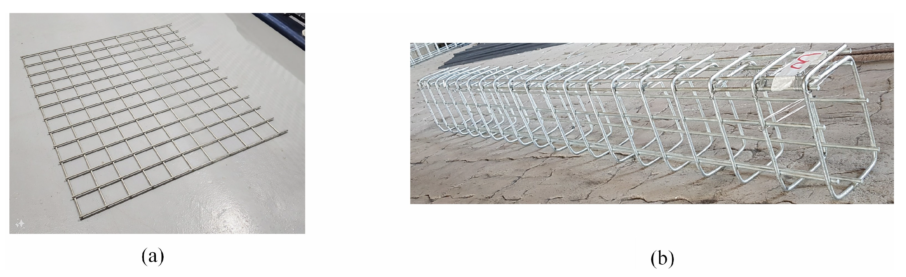
WWR consists of a mesh-like sheet made from steel wires welded together at precise intervals, as shown in
Figure 1a. This mesh is then formed into a closed cage, as shown in
Figure 1b. The closed-cage WWR system offers several advantages over traditional reinforcement methods. It facilitates faster and easier installation by eliminating the labor-intensive task of tying individual ties to rebars, allowing the closed cage to be directly positioned within the formwork. This not only reduces the time and effort required for reinforcement installation but also ensures consistent and uniform spacing due to the precise welding intervals. For example, substituting pre-made WWR stirrup cages in place of loose ties cut the reinforcement installation time by as much as 75% in a high-rise project [
1].
The adequate confinement of the core of a concrete column is crucial for maintaining its load-bearing capacity, particularly after the spalling of the concrete cover. Transverse reinforcement plays a vital role in providing effective confinement to the concrete core by restricting lateral deformations of the longitudinal reinforcement under the application of axial compression. This mechanism enhances the column’s ability to resist large compressive forces by protecting the concrete core and prohibiting the buckling of the longitudinal rebars following concrete cover spalling. It also delays the initiation and slows down the propagation of cracks at service and ultimate load levels. The use of a closed-cage system, characterized by closely spaced longitudinal and transverse wires, is expected to optimize confinement within the concrete core and improve the overall structural performance and stability.
The structural behavior of conventionally steel-reinforced concrete columns by longitudinal rebars and lateral ties under the action of axial compression is well established through experimental testing and theoretical research. Good references on the subject include the old textbook by Park and Paulay [
2] and the more recent one by Wight [
3]. In addition, joint ACI-ASCE Committee 441, Reinforced Concrete Columns, provides publications that support disseminating research findings from experimental and analytical studies conducted on reinforced concrete columns [
4,
5].
Under compressive loading, concrete undergoes hardening up to its peak stress, with maximum stress levels increasing proportionally to the degree of lateral confinement provided by the internal lateral reinforcement. Post-peak behavior is heavily influenced by confinement; that is, low confinement leads to a softening response and brittle failure, whereas high confinement transitions the material to ductile hardening. Confinement provided by closed internal ties delays cracking, restrains outward bulging, shifts the failure mode from brittle to ductile, and ultimately enhances the structural integrity and safety of the concrete members under extreme loading conditions. At extremely high confining pressures, the dilatancy of the concrete contained within the core can be entirely suppressed. The ultimate strength and stiffness of confined concrete columns are substantially improved by increasing the cross-sectional area and reducing the spacing of the transverse reinforcement. This is especially beneficial for structures made with high-strength concrete, because although such concrete offers a superior compressive capacity, it generally exhibits reduced ductility, necessitating specific confinement strategies. It should be noted that while the influence of confinement on concrete’s stiffness is relatively modest, its impact on strength, ductility, residual strength, and toughness is significant [
6,
7]. The stiffness degradation, mesostructured changes, and mechanical behavior of recycled aggregate concrete with and without micro-steel fibers under uniaxial compression have been addressed by Wang et al. [
8,
9].
With regard to the use of WWR, also termed welded wire fabric (WWF) or welded wire mesh (WWM), various studies over the past few decades have explored the use of such a reinforcement for the confinement of cores in concrete columns to evaluate their structural performance relative to those employing conventional ties. For example, early experimental investigations demonstrated the potential of WWR for effective confinement. For example, one of the earliest studies involving the use of welded wire in columns was the work of Saatcioglu and Razvi [
10], who developed an analytical model for the stress–strain relationship of confined concrete under axial compression. The model was verified against a large number of experimental tests on columns with a wide range of effective lateral confinement. The approach accounts for various cross-sectional shapes and reinforcement configurations, including welded wire fabric, by superimposing individual confinement effects. Another early study on the subject was conducted by Mau et al. [
11], who tested 20 reinforced concrete columns to evaluate the effectiveness of using parallel stacks of WWF as a transverse reinforcement for confinement. The results showed that longitudinal spacing had the greatest impact on strength, while grid-type variations had a minimal effect. They proposed a lower-bound formula estimating strength increases of up to 40%. The study concluded that WWF, with a proper design, effectively provides lateral confinement in columns.
In 2001, Lambert-Aikhionbare and Tabsh [
12] evaluated the utilization of welded wire reinforcement (WWR) sheets as an alternative to conventional ties in high-strength concrete (HSC) columns. Testing 14 full-scale columns, they found that WWR confinement increased the load capacity by at least 15% and ductility by up to 250%, given a transverse reinforcement ratio above 3.5%. They developed a stress–strain model highlighting the volumetric ratio of WWR as key to performance, laying the groundwork for further research on WWR as a viable lateral reinforcement. Building upon his earlier research, Tabsh (2007) [
13] further investigated the performance of high-strength concrete (HSC) columns reinforced with welded wire fabric (WWF) sheets under axial compression. This study expanded on his previous work by analyzing a broader range of reinforcement configurations and developing a refined mathematical model to predict the confinement effects of WWF. The obtained results reinforced the conclusion that WWF significantly enhances both strength and ductility, particularly when the volumetric ratio of lateral reinforcement exceeds 3.5%. Later in 2011, Kusuma et al. [
14] found that square columns containing WWR sheets as a transverse reinforcement carried roughly 20–25% higher loads than those with traditional closed ties but with a slightly reduced post-peak ductility.
Recognizing the benefits of WWR, researchers have also explored hybrid confinement techniques to maximize both its structural and practical advantages. In 2016, El-Kholy and Dahish [
15] proposed augmenting conventional ties with a layer of expanded metal mesh (EMM). Their tests on one-third-scaled columns showed that adding a metal mesh layer increased the ultimate load capacity by about 11–18.6% and improved ductility and energy absorption, while allowing a reduction of up to 70% in the volume of traditional ties without sacrificing strength. In another study, Tahir et al. [
16] evaluated welded wire mesh (WWM) as an additional confinement for reinforced concrete (RC) square columns under axial loading, comparing WWM placement inside vs. outside the core. Four specimen types were tested, one including inner WWM confinement, a second containing outer WWM confinement, a third having only stirrups, and a fourth made with plain concrete that served as a control. The results showed that outer WWM confinement was most effective, increasing the axial capacity by 15.7% and core strength by 23%, outperforming inner confinement by 6.9% and 63%, respectively. The strength enhancement was 76% higher with outer WWM, which also improved the crack resistance and prevented bar buckling. Building upon the findings of the previously reported study, El-Kholy et al. [
17] studied the structural behavior of 30 columns having square cross-sections and reinforced with either expanded metal mesh (EMM) or welded wire mesh (WWM) to determine lateral steel reinforcement’s effectiveness against preloading by up to 65% of the capacity and post-heating by up to 500 °C. The outcome of the experimental tests showed that the compressive strength of EMM and WWM reinforced columns increased by 2.7–49% with respect to the corresponding tied columns, with an evident enhancement in ductility. The results revealed that metal mesh strength had the upper hand in magnifying the ultimate load and ductility. Furthermore, both the expanded and welded steel meshes improved the fire resistance by decreasing the concrete core temperature and lessening the reduction in ultimate strength of the post-heated columns compared to the reference tied columns.
More recently, Manaha and Suprobo [
18] evaluated the retrofitting potential of WWM as jackets for 800 mm tall concrete columns having a square 220 mm cross-section. Two WWM configurations were tested, using 2 mm diameter wires spaced at 25 and 50 mm. The results of the study showed that the narrow-spacing configuration attained a confined compressive strength of 25.7 MPa at a corresponding strain of 0.00525 and ultimate strain of 0.0380, whereas the wide-spacing configuration reached 24.4 MPa at a corresponding strain of 0.00838 and ultimate strain of 0.0343. In 2021, Chitra and Rugmini [
19] examined reinforced concrete columns subjected to axial load and reversed cyclic lateral loading (simulating seismic forces) with WWR used as the lateral ties. Their results demonstrated substantial improvements in hysteretic behavior, lateral load capacity, and energy dissipation, particularly when three grids of WWM were used. Later in 2022, Bastami et al. [
20] investigated the use of hexagonal chicken-wire mesh (HCWM) as a supplementary confinement mechanism for one-third-scale high-strength concrete columns subjected to constant axial loads and reversed cyclic lateral displacements. The study involved eight specimens designed to simulate ordinary-, intermediate-, and special-ductility columns. The results showed that applying two HCWM layers around the transverse reinforcement enhanced the ultimate lateral deformation by up to 21%, increased cumulative ductility by 50%, and improved energy dissipation by 175% in ordinary columns. Additionally, peak lateral strength increased by 15% in ordinary columns and 22% in intermediate columns, with a minimal enhancement observed in the special-ductility columns. In 2022, Abadel et al. [
21] investigated the post-fire performance of reinforced concrete columns retrofitted with welded wire mesh (WWM) jackets and carbon fiber-reinforced polymer (CFRP) strips. The columns were exposed to elevated temperatures of 600 °C for a duration of 3 h, resulting in an axial load capacity reduction of approximately 39% in the control circular columns and 29% in the control square ones. Retrofitting with two layers of WWM restored the ultimate axial strength by up to 104% in the circular columns and 58% in the square columns. Also, WWM was more effective in regaining axial stiffness, while CFRP contributed primarily to improved ductility.
Despite the many advantages that welded wire reinforcement possesses, past experience with the use of WWR in structural applications has been limited to its utilization as secondary reinforcement in slab-on-grades, flexural reinforcement in pavements, and shear reinforcement in precast concrete beams. With regard to the usage of such a reinforcement in columns, the literature review component of the study showed that WWR can be effectively used in the form of flat sheets that are placed within the member’s cross-section to replace ties across the length of the elements. Other applications involved the hybrid use of a WWR steel cage together with conventional ties. With regard to strengthening, WWR has been used extensively as a reinforcement in a concrete jacket around an existing member. This study investigates the effectiveness and potential use of WWR in columns when fabricated into a closed-cage configuration. This configuration has not been comprehensively addressed in prior research; thus, if deemed feasible, it will open up a new area of application and will provide an understanding of the role that WWR plays as confinement reinforcement in vertical members subjected to axial compression.
2. Research Significance, Objectives, and Scope
Reinforced concrete columns under extreme loads often suffer from inadequate ductility, necessitating a lower design strength reduction factor (0.65) for tied columns compared to spirally reinforced ones. Additionally, tying transverse reinforcement is labor-intensive and subject to a higher potential for human error intervention. A promising alternative is using welded wire reinforcement (WWR) closed cages, which provide better confinement, improving the strength, modulus of elasticity, and ductility of the confined concrete. WWR also simplifies installation by eliminating the need for manual tying, minimizing labor anomalies. Investigating columns laterally reinforced with WWR can validate their structural benefits, making them a viable and cost-effective alternative to conventional reinforcement systems. Very few previous studies have been conducted in the past on concrete columns reinforced with WWR closed steel cages.
This study aims to experimentally evaluate the feasibility of utilizing welded wire reinforcement as a lateral reinforcement in concrete columns for the sake of improving the mechanical properties of the concrete within the core. To achieve this objective, eight one-third-scale columns were tested, with four reinforced laterally using WWR and the remaining four reinforced with conventional ties. All the columns were subjected to concentric axial loading using a Universal Testing Machine (UTM) under displacement-controlled condition. The investigation focused on assessing core confinement, strength, modulus of elasticity, and ductility. To precisely monitor column behavior during loading, two Linear Variable Differential Transformers (LVDTs) were positioned on opposite sides at the mid-height of each column. These devices provided real-time data on the deformation of the column’s central region. The data collected were analyzed, and a comparative assessment between WWR and conventional reinforcement systems was conducted. The experimentally based study is limited to short columns having a square cross-section and constant longitudinal reinforcement ratio and subjected to concentric monotonic loading. It does not address high-strength or recycled materials.
3. Experimental Program
The experimental program includes eight one-third-scale columns, each measuring 1000 mm in height with a cross-sectional dimension of 200 mm by 200 mm. Of the eight, four columns were laterally reinforced with conventional ties, representing control specimens, while the remaining four were reinforced with WWR, representing the experimental alternative. The clear concrete cover on the lateral reinforcement was 15 mm, which is about one-third lower than the 40–50 mm used in full-scale exposed columns, depending on the rebar size. This reduction was necessary to maintain a realistic reinforcement placement and core concrete proportions within the scaled-down specimens, ensuring that the confinement effectiveness of the lateral reinforcement remained comparable to that of full-scale structures. As a result, the concrete core dimension was 170 mm × 170 mm minus the longitudinal rebars’ and wires’ areas. The experimental program was divided into two groups based on the concrete compressive strength: Group 1 consisted of columns with a relatively low nominal compressive strength (f′c = 30 MPa), while Group 2 included columns with a relatively high nominal compressive strength (f′c = 40 MPa). The actual concrete compressive strengths for Groups 1 and 2 at the time of testing were 34.3 and 43.5 MPa, respectively.
All columns were cast with a nearly uniform longitudinal reinforcement ratio (ρ), averaging 1.49%. In accordance with ACI 318-25 [
22] guidelines, this ratio was determined by dividing the total area of longitudinal reinforcement by the column’s gross cross-section area. With regard to the transverse reinforcement, the tie spacing in a tied column that is equivalent to a WWR reinforced column was determined such that both columns have the same transverse steel reinforcement ratio. This ratio is defined as the volume of a single transverse reinforcement (tie or wire) to the volume of concrete containing the transverse reinforcement. For example, for the No. 6 wire at a 50 mm spacing in the WWR reinforced column, the corresponding spacing of a No. 8 tie would be 89 mm in a tied column. Likewise, for the No. 4 wire at a 25 mm spacing in the WWR reinforced column, the corresponding spacing of a No. 8 tie would be 100 mm in a tied column.
To systematically characterize the columns in the experimental program, a designation system was developed that incorporates five key variables. The first variable is an initial letter indicating the type of vertical reinforcement: (W) for WWR and (T) for ties. The second variable is a numeral representing the diameter, in millimeters, of the longitudinal rebars. The third variable denotes the diameter, in millimeters, of either the wires or ties. The fourth variable is a numeral indicating the spacing, in millimeters, of the transverse reinforcement, with the 89 mm tie spacing being rounded to 90 mm. Finally, the fifth variable specifies the nominal concrete compressive strength, in MPa. For instance, the designation W-8-6-50-30 identifies a column with WWR as the transverse reinforcement, 8 mm diameter longitudinal rebars, 6 mm diameter wire, a transverse reinforcement grid spaced at 50 mm, and a nominal concrete compressive strength of 30 MPa.
Table 1 provides a comprehensive overview of the reinforcement details and nomenclature for all eight columns considered in the study.
3.1. Specimen Fabrication
The welded wire steel cages were fabricated in the laboratory using a manually operated bending machine specifically designed for this purpose. Throughout the fabrication process, close attention was taken to ensure that both the dimensions of the steel cages and the specified concrete cover adhered to the established tolerances. Precision in these aspects was crucial to maintaining the structural integrity and consistency of the specimens. Experience from the manufacturing process showed that manual fabrication of closed reinforcement steel cages in the laboratory was simple, efficient, and easy. It is expected that with the automation of such a scheme, the process can become more reliable, economical, and suitable for mass production. To achieve uniformity and quality control in the concrete placement, the concreting work was outsourced to a reputable ready-mix concrete supplier. This ensured that the concrete mix met the required specifications, including consistency, strength, and durability, while also minimizing the potential variability associated with manual on-site mixing.
Figure 2 shows the steel cage fabrication and casting of specimens.
3.2. Material Properties
In this section, the experimentally obtained mechanical properties of the concrete and steel materials used in the specimens are provided and discussed. As previously mentioned, two distinct concrete mix designs and two different types of steel reinforcement were utilized. Additionally, the study considers steel wires with diameters of 4 mm and 6 mm, along with reinforcing bars measuring 8 mm and 14 mm in diameter.
3.2.1. Concrete
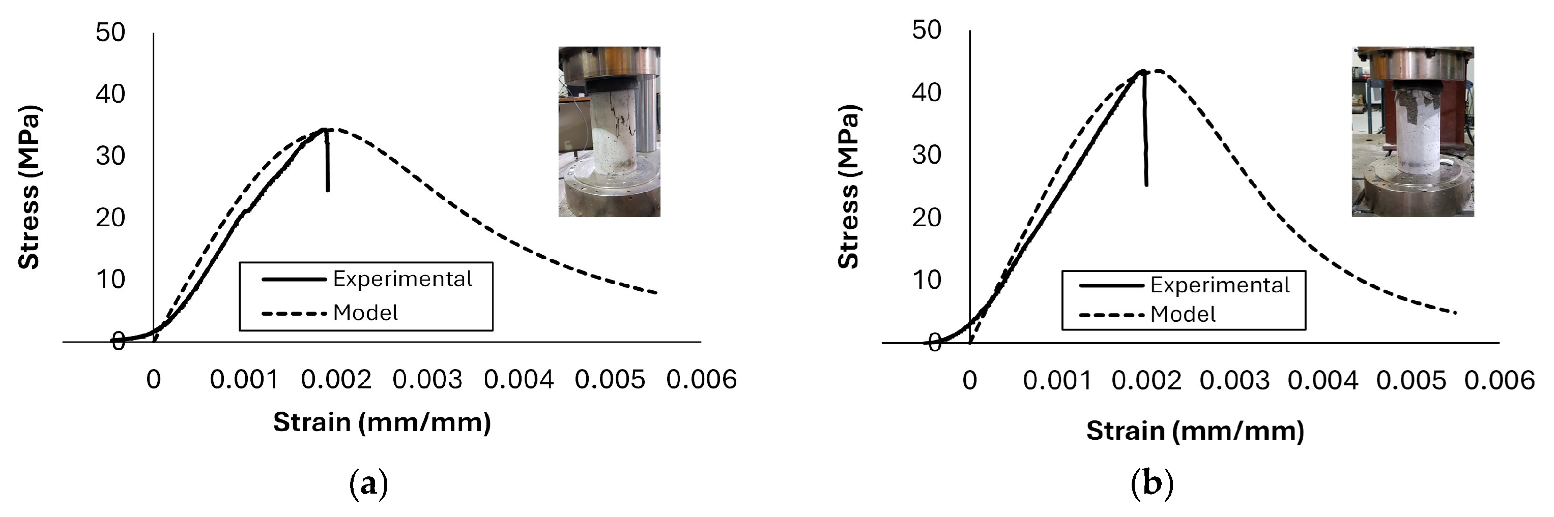
The concrete mix for the columns was designed to achieve target compressive strengths of 30 MPa and 40 MPa. The actual compressive strengths used in the analysis were determined through experimental testing of 150 mm × 300 mm concrete cylindrical samples. The test results showed that at the time of testing, the lower-strength mix achieved compressive strengths of 34.3 MPa, while the higher-strength mix reached 43.5 MPa. The fine aggregate that was used in the mixes was composed of dune and washed sand, having a fineness moduli equal to 3.56 and 4.90. The testing of the 10 mm coarse aggregate resulted in a bulk specific gravity of 2.60, apparent specific gravity of 2.68, absorption of 1.4%, moisture of 0.9%, abrasion loss of 23%, and crushing value of 18%. One cubic meter of the 30 MPa nominal concrete mix includes 925 kg of fine aggregate, 986 kg of coarse aggregate, 308 kg of cement, and 180 kg of water. The corresponding masses for one cubic meter of the 40 MPa nominal concrete mix are 708 kg of fine aggregate, 1010 kg of coarse aggregate, 496 kg of cement, and 184 kg of water. Since the concrete cylinder tests were conducted under a load-controlled environment, it was not possible to capture the descending part of the stress–strain relationship from the test. Hence, to characterize the complete compressive behavior of the concrete, stress–strain curves were generated for both mixes using the Thornfeldt et al. [
23] model, which was applied based on the experimentally obtained maximum stress values.
Figure 3 shows the experimental and corresponding theoretical stress–strain curves for both mixes at the time of testing. Note that the softening part of the experimental stress–strain relationships at the beginning of the test is due to the use of a neoprene cap on the rough surface of the concrete cylinder to preclude premature sample failure due to stress concentration. Note that the experimental and theoretical curves are plotted on the same diagram by matching the peak point.
3.2.2. Steel
Two different types of reinforcing steel were utilized in this study, rebars and welded wire reinforcement (WWR). Closed WWR cages were used as a replacement for conventional ties in four out of the eight tested columns. The rebars were used as a longitudinal reinforcement. The mechanical properties of the reinforcing steel were determined through experimental testing on 300 mm long representative steel specimens.
Figure 4 shows the stress–strain curves for all the steel specimens. The modulus of elasticity for WWR was found to be 207 GPa, whereas the rebars exhibited a modulus of 200 GPa, indicating a slight variation in stiffness between the two reinforcement types. The yield strength of the wires was determined using the 0.2% offset method, in accordance with ASTM A1064M-24 [
24]. Similarly, the yield strength for rebars was determined using the 0.2% offset method, in accordance with ASTM A615M-24 [
25]. The experimentally measured yield strengths of the WWR wires were 560 MPa for 4 mm diameter wires and 390 MPa for 6 mm diameter wires. For rebars, the recorded yield strengths were 560 MPa for 8 mm diameter bars and 520 MPa for 14 mm diameter bars. These results highlight the inherent variations in yield strength based on diameter and type, which are critical for assessing load-bearing capacity and ductility. These mechanical properties provide insights into the behavior of the reinforcement materials and their influence on the overall structural performance of the tested columns.
3.3. Test Setup and Instrumentation
The columns were placed inside a 2500 kN Universal Testing Machine and subjected to concentric axial compression. They were confined at their top and bottom extremities by structural steel angles in order to preclude premature failure due to stress concentration. They were instrumented with strain gauges and Linear Variable Differential Transformers (LVDTs) and tested using a Universal Testing Machine (UTM). The strain gauges were mounted on the surfaces of two of the four longitudinal rebars in order to examine the change in the stress of the reinforcement during testing. Two LVDTs were placed vertically on two opposite faces at the mid-height of the specimens to ensure the proper alignment of the column at the start of the test and observe the axial deformation between two points that are 300 mm apart.
Figure 5 shows the test setup for the specimens in the laboratory. The tests were conducted under a displacement-controlled condition at a constant rate of 0.2 mm/min.
4. Methodology
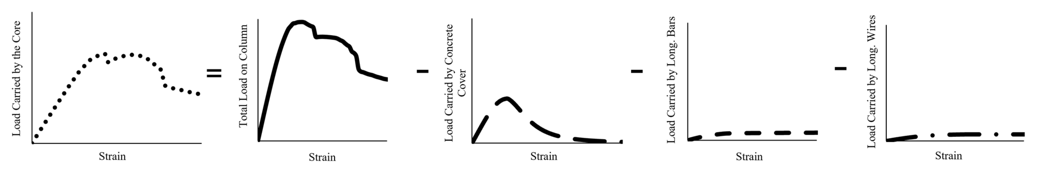
In this study, the behavior of confined concrete is examined by isolating the response of the core concrete from the experimental data obtained from the tested columns. To achieve this, the contribution of the concrete cover is quantified through standard concrete cylinder testing, which provides an independent measure of its load-bearing capacity. Similarly, the contributions of longitudinal steel rebars and WWR wires are determined through tensile tests conducted on steel specimens, assuming a perfect bond between the reinforcement and the surrounding concrete matrix, which allows the tensile properties derived from the steel specimen tests to be reliably correlated with the behavior observed in the column tests. Once these individual contributions are characterized, the core concrete response is derived by subtracting the load contributions of each component at corresponding strain levels from the total load recorded by the Universal Testing Machine (UTM). The strain values of the tested columns are determined using two Linear Variable Differential Transformers (LVDTs) with a gauge length of 300 mm, mounted at the center of the column.
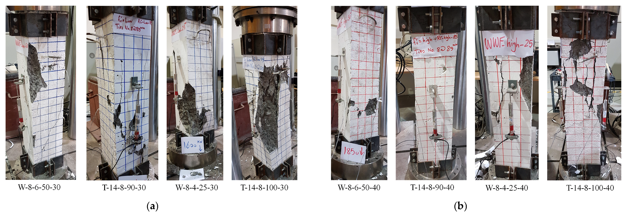
Figure 6 summarizes the method used to filter out the concrete cover and longitudinal steel reinforcement contribution from the response, in order to obtain the behavior of the core. Note that the load carried by the concrete cover is obtained by multiplying the stress corresponding to a given strain by the area of the cover. Likewise, the load carried by the longitudinal bars or wires is equal to the product of the stress corresponding to a given strain by the matching area of the bars or wires. The final step consists of dividing the load on the concrete core by the area of the core in order to arrive at the confined concrete stress–strain relationship. During the different stages of the column tests, cracks propagation was tracked visually, and their intensities were measured manually. All the columns exhibited similar failure modes that were characterized by initial nonuniform crackling, extensive concrete cover spalling, and eventual core concrete crushing. In general, the WWR reinforced columns demonstrated less concentrated cover spalling than their corresponding tied columns. The lateral expansion of the confined core at high compressive load levels induced tensile stresses within the column’s cross-section, leading to concrete cover spalling. In the tied columns, this phenomenon exposed the longitudinal reinforcement, resulting in rebar buckling between the ties. No rebar buckling was evident in the WWR reinforced concrete columns due to the protection of the rebars by the welded wire mesh. With further loading, the confined concrete core experienced progressive crushing, leading in some cases to diagonal shear plane failure. The failure patterns of all the tested specimens after the ultimate load was reached are shown in
Figure 7. Note that the T-14-8-90-40 tied column showed no sign of cracks during testing, as the Universal Testing Machine (UTM) reached its maximum load capacity prematurely before the column’s ultimate strength was attained.
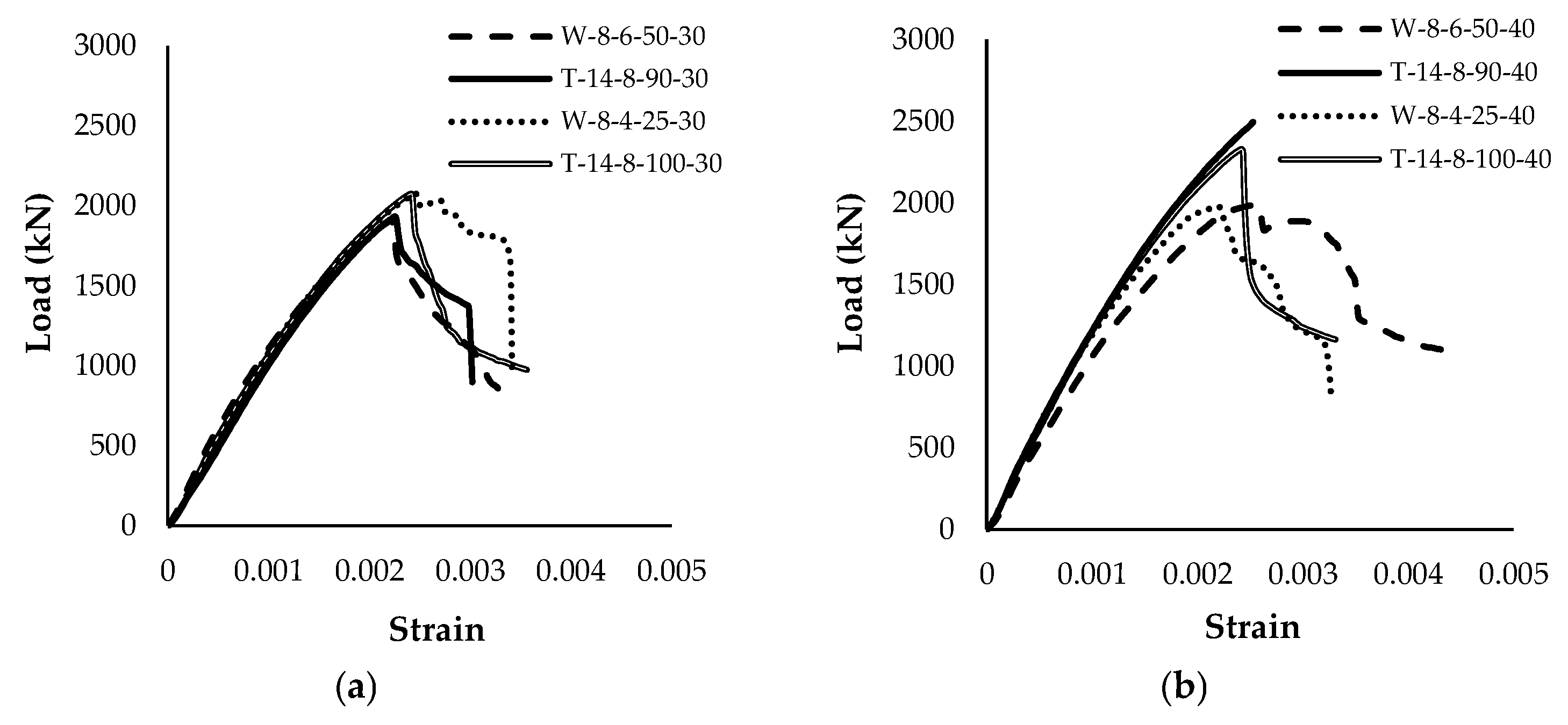
The load–strain relationships of the tested specimens are shown in
Figure 8. Such curves provide a critical insight into the structural behavior of the columns under applied loading conditions. In the ascending portion of the curve, the column exhibits elastic behavior, where the relationship between load and strain is nearly linear. This phase primarily reflects the initial stiffness of the column and the effectiveness of the composite action between the concrete and the embedded reinforcement. The initial stiffness is governed by the properties of the concrete, reinforcement ratio, and confinement provided by transverse reinforcement. As the applied load increases, microcracking initiates within the concrete matrix, though the structure remains within its elastic limit. As the curve progresses towards its peak, the column reaches its ultimate load-bearing capacity. This point is often associated with the onset of inelastic deformations and is characterized by significant material responses such as the initiation of concrete cover spalling and yielding of the longitudinal reinforcement. Beyond the peak, the descending portion of the curve represents the post-peak behavior of the column, where its load-bearing capacity begins to degrade. This phase is typically linked with concrete crushing, reinforcement buckling, and bond degradation between steel and concrete. Unlike the ductile behavior of spirally reinforced columns, the behavior of tied columns with rectilinear cross-sections is generally brittle in nature, as depicted by the relatively steep slope of the descending part of the load–strain diagrams. For the WWR reinforced columns, the tests indicated that 3 out of the 4 columns with such a lateral reinforcement exhibited ductile behavior, compared with their tied counterparts. The residual strength of the column in this region depends on several factors, including the level of confinement provided by transverse reinforcement, the ductility of the steel, and the integrity of the core concrete. The slope of the descending branch can vary significantly based on the column’s reinforcement details and material properties, affecting the failure mode of the structure.
5. Results and Discussions
The experimental tests focused on recording the applied load, column deformation, and LVDT readings, providing a comprehensive dataset for analysis. These data were processed to generate load–strain curves for each column, which were subsequently used to study key structural properties, including ultimate strength and core confinement. These plots formed the basis of comparisons between the behavior of WWR reinforced columns and their counterparts reinforced with conventional ties. Theoretical prediction by the ACI 318-25 [
22] code equation for tied columns was utilized to forecast the ultimate strength of the columns.
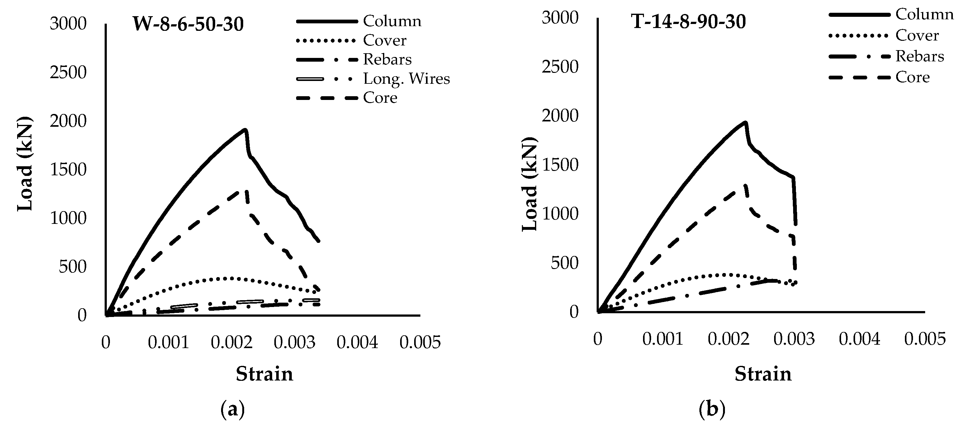
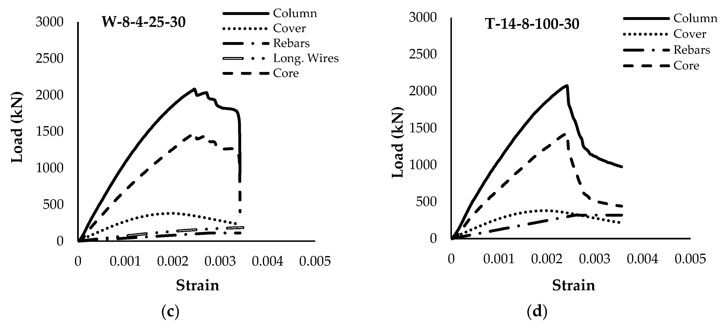
Figure 9 shows the load–strain curves of the entire cross-section (referred to as a column in the figures), plus the individual load–strain diagrams of the material constituents (concrete cover, longitudinal steel rebars and wires—if present—and concrete core) for the four samples in Group 1. The corresponding load–strain curves for Group 2 are presented in
Figure 10.
5.1. Behavior of Confined Concrete
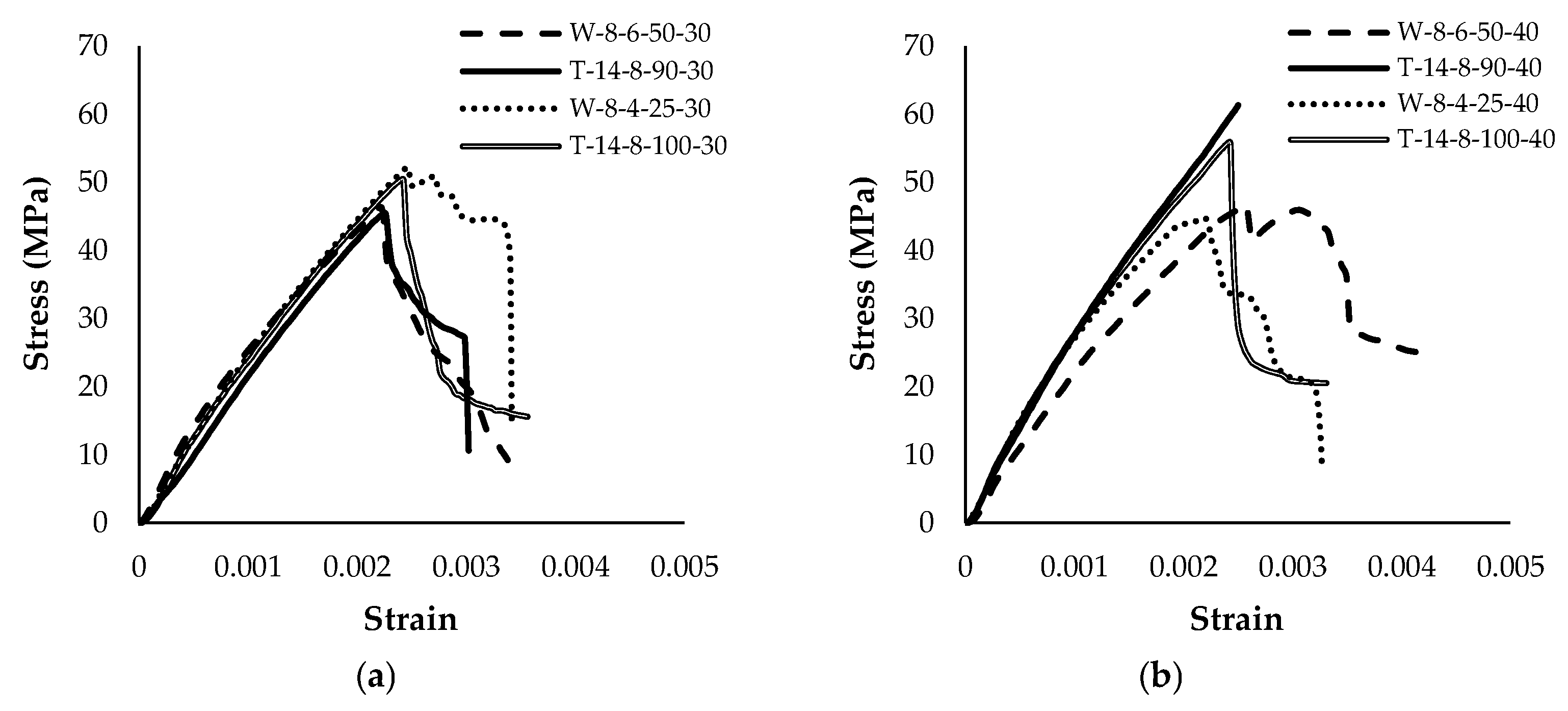
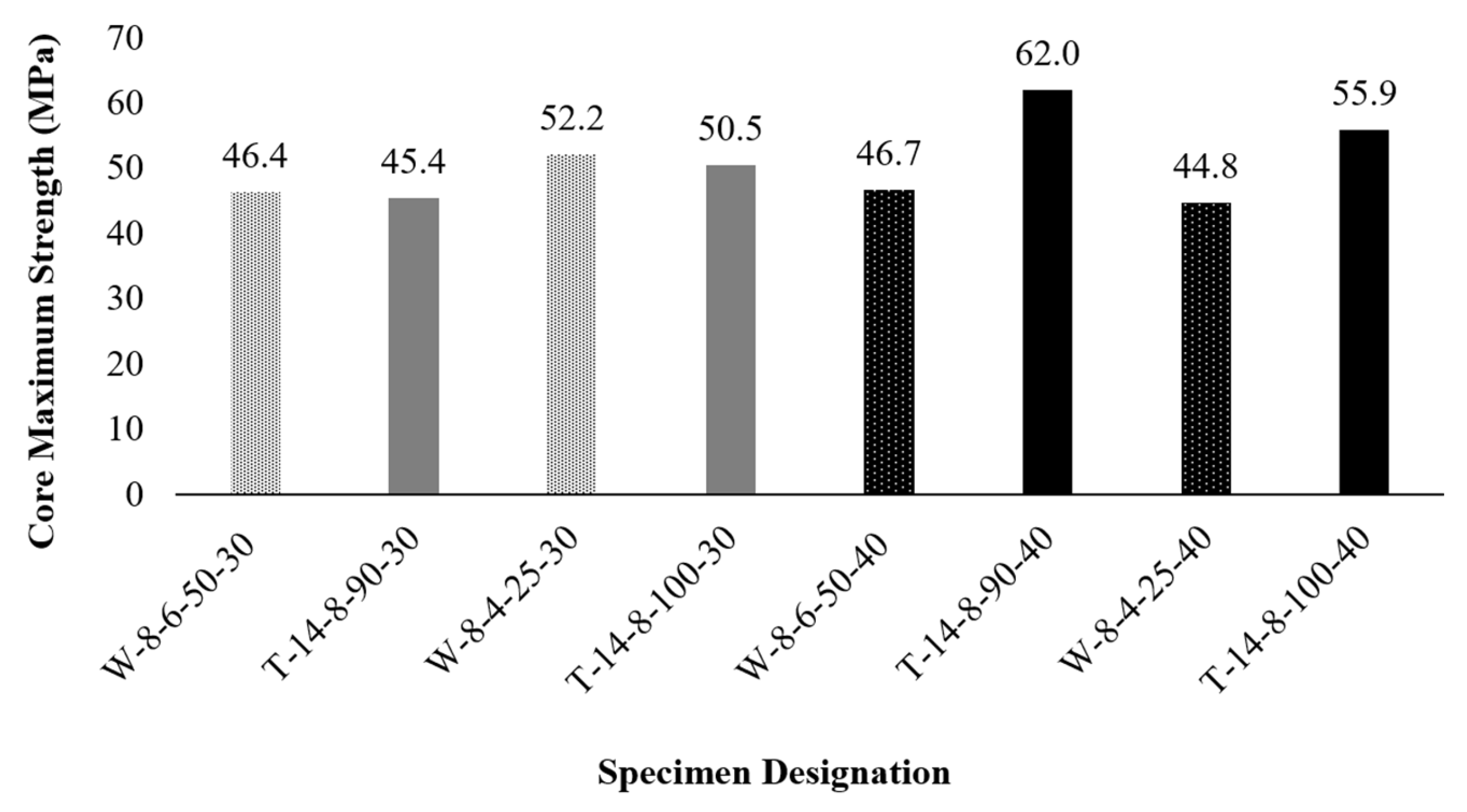
Concrete confinement plays a crucial role in enhancing the strength, ductility, stiffness, and overall performance of structural elements subjected to axial load. Understanding the behavior of confined concrete is essential for determining its contribution to structural performance, enabling the development of optimized reinforcement details, thereby improving structural resilience and longevity. The confined concrete behavior of the tested columns, as shown in
Figure 11, illustrates these performance differences across the various reinforcement configurations and concrete strengths used in this study.
In Group 1 (lower-strength concrete), the WWR-confined column W-8-6-50-30 attained a maximum core stress of 46.4 MPa, which is slightly higher than the 45.4 MPa achieved by its tied counterpart T-14-8-90-30. Another WWR column in the same group, W-8-4-25-30, achieved 52.2 MPa, exceeding the 50.5 MPa reached by T-14-8-100-30. On average, the WWR-confined columns within Group 1 showed a 2.7% higher core strength than their tied counterparts. These findings indicate that, for moderate-strength concrete, the continuous mesh and closer spacing of WWR can effectively restrain lateral expansion and delay the onset of failure, resulting in a slightly higher core strength than conventional ties.
In contrast, in Group 2 (higher-strength concrete), the tie-reinforced columns outperformed their WWR-confined counterparts. The tie-reinforced specimen T-14-8-90-40 reached a maximum core stress of 62.0 MPa, notably exceeding the 46.7 MPa observed for W-8-6-50-40. A similar trend was observed for T-14-8-100-40, reaching 55.9 MPa, compared to the 44.8 MPa attained by W-8-4-25-40. On average, the tie-confined columns within Group 2 showed a 28.8% higher core strength than their WWR-reinforced counterparts. These results indicate that, in higher-strength concrete, larger-diameter ties provide a more robust confining pressure than the tested WWR configurations. Note that the T-14-8-90-40 column did not exhibit failure during testing, as the Universal Testing Machine (UTM) reached its maximum load capacity before the column achieved its ultimate strength. This behavior is evident in the corresponding stress–strain curve, which lacks a distinct peak for T-14-8-90-40, indicating that the ultimate strength was not fully captured.
The difference in confinement efficiency between Group 1 and Group 2 highlights the importance of considering both the concrete strength and the geometry of the reinforcement (i.e., wire or tie diameter and spacing) when selecting an optimal confinement system. Overall, these observations confirm that WWR can be a viable alternative to conventional ties, particularly in columns of moderate compressive strength where continuous mesh and closer wire spacing can effectively enhance the concrete’s load-bearing capacity. However, in higher-strength columns, larger diameter ties may provide better confinement.
5.2. Effect of Concrete Compressive Strength on Confinement
The effect of concrete compressive strength on the confinement effectiveness of the tested columns was evaluated by comparing the performance of columns in Group 1 with their corresponding counterparts in Group 2, as shown in
Figure 12. As anticipated, the results showed that an increase in concrete compressive strength consistently led to a higher maximum core strength. Across all the tested columns, the increase in maximum core strength between the two strength levels was moderate, averaging 7.7%. A notable deviation from this trend was observed in column W-8-4-25-30 and its counterpart W-8-4-25-40, where the column with a lower compressive strength exhibited a higher maximum core strength. The overall difference between the effect of the two strength levels on the confinement of the columns remains relatively small, as the gap between their compressive strengths is not substantial.
5.3. Effect of Grid Spacing and Wire Diameter on Confinement
In this study, the grid spacing and wire diameter of the WWR are linked together; hence, they are dependent variables. This is because a small wire diameter of 4 mm is used with a narrow grid spacing of 25 mm, and a large wire diameter of 6 mm is used with a wide grid spacing of 50 mm. The results of the experimental tests showed that the effect of grid spacing and wire diameter on concrete confinement are influenced by the unconfined concrete strength, as shown in
Figure 13. The core strength enhancement averages about 44% for the two WWR reinforced columns that are made with f′
c = 34.3 MPa. Alternatively, the core strength enhancement averages about 5% for the two WWR reinforced columns that are made with f′
c = 43.5 MPa. There is no definite trend with regard to the impact of the size of the grid and wire diameter on the strength of the confined core. The findings of this study strongly suggest that WWR is more effective in confining cores made with a lower strength than higher-strength concrete.
5.4. Effect of Confinement on Modulus of Elasticity of Confined Concrete
In this study, the modulus of elasticity (
E) of the confined concrete within the core of the columns was determined by drawing a secant line from the origin of the stress–strain curve to the point corresponding to 40% of the peak confined concrete stress (
). This approach is based on the method included in ASTM C469 [
26] to determine the modulus of elasticity of concrete. The corresponding strain at that 40% stress level, denoted by
was used to establish a consistent benchmark for comparing the elastic responses of the specimens.
where all variables are defined.
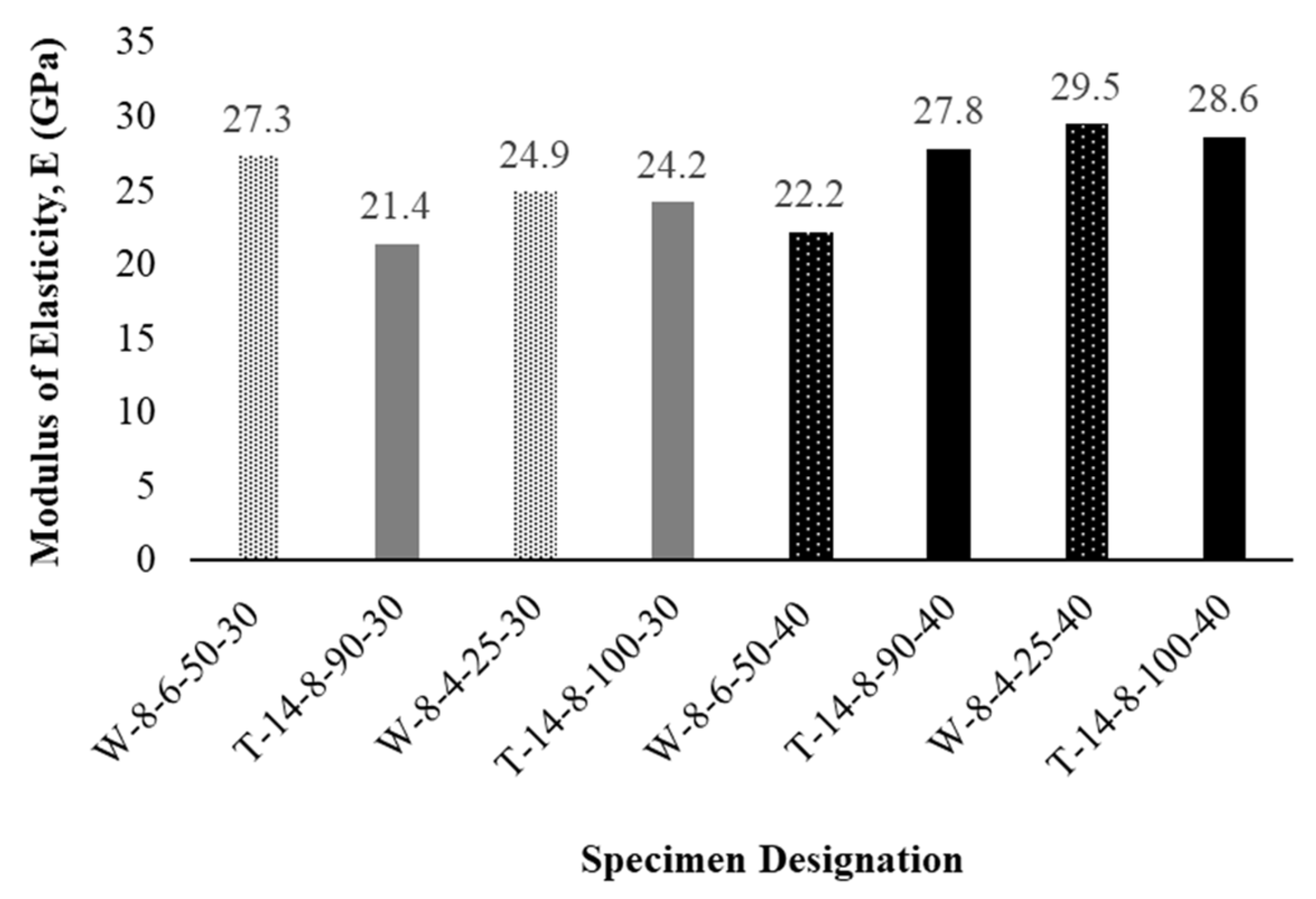
Based on this definition, the calculated modulus of elasticity values for all the tested columns range from 21.4 GPa to 29.5 GPa. Columns reinforced with WWR showed, on average, a slightly higher modulus of elasticity of 26.0 GPa compared to 25.5 GPa for columns reinforced with conventional ties, indicating that WWR reinforced columns demonstrated a 2.0% increase in their modulus of elasticity. This modest improvement is primarily attributed to the continuous confinement provided by the WWR cage, which mitigates early lateral expansion and delays cracking at lower stress levels. Among the tested columns, the highest modulus of elasticity of 29.5 GPa was observed in specimen W-8-4-25-40, underscoring the positive influence of closer wire spacing and a higher concrete strength level. In contrast, column T-14-8-90-30 exhibited the lowest modulus of elasticity of 21.4 GPa, reflecting the reduced confinement effectiveness of tie reinforcement, which can foster earlier cracking at moderate stress levels. Overall, the observed modulus of elasticity trends indicates that WWR slightly enhances the elastic performance of concrete columns, while offering practical benefits in construction efficiency.
Figure 14 shows the modulus of elasticity values for all the tested columns.
5.5. Effect of Confinement on Ductility
In this study, the ductility index (µ) of the samples was defined as the ratio of the confined concrete strain at 85% of the peak stress on the descending branch of the stress–strain curve
to the confined concrete strain at 85% of the peak stress on the ascending branch
:
where all variables are defined.
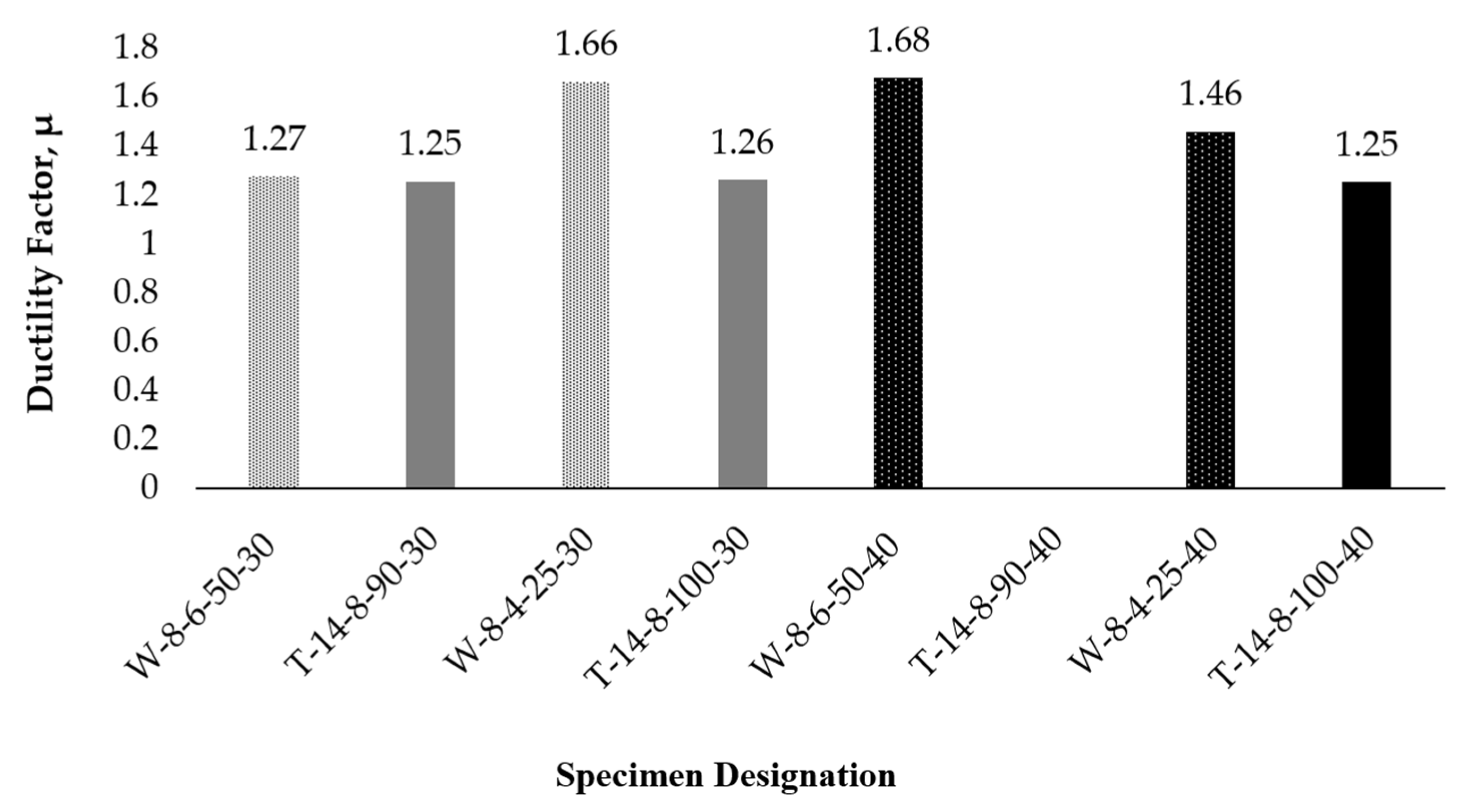
The ductility factors determined from experimental results clearly demonstrate that all columns reinforced with WWR exhibited a consistently higher ductility compared to columns reinforced with ties. WWR columns exhibited, on average, a higher ductility factor of 1.52, compared to 1.25 for columns reinforced with conventional ties. This indicates that WW reinforced columns demonstrated, on average, a 21.0% increase in ductility over tie reinforced columns. This enhancement is attributed to the continuous lateral confinement provided by WWR, which delays the onset of local failures and promotes a more gradual post-peak response. In contrast, tie reinforced columns showed relatively uniform ductility values between 1.25 and 1.27, indicating a stable, though moderate, enhancement in deformation capacity. It is worth noting that the ductility factor for column T-14-8-90-40 could not be determined because this column did not experience complete failure during testing; consequently, the descending portion of its stress–strain curve was unavailable.
Overall, these findings indicate that WWR reinforcement provides a higher ductility enhancement compared to conventional ties, making it a more effective confinement method for improving the deformation capacity and post-peak performance of reinforced concrete columns.
Figure 15 shows the ductility factors for all tested columns.
6. Theoretical Prediction
In this section, theoretical predictions for the axial compressive strength (P
o) of the tested columns at the ultimate were calculated and compared to the experimentally obtained ultimate strength (P
exp). The axial load capacity equation of the reinforced concrete columns, following the guidelines specified by the ACI 318-25 code [
22], is presented below:
where P
o is the axial compressive strength (N), f′
c is the concrete compressive strength (MPa), A
g is the gross cross-sectional area of the column (mm
2), A
st is the total area of longitudinal reinforcement consisting of A
R and A
w (mm
2), f
yR is the yield strength of longitudinal rebars (MPa), A
R is the area of longitudinal rebars (mm
2), f
yw is the yield strength of longitudinal wires (MPa), and A
w is the area of longitudinal wires (mm
2). Note that the terms f
yw and A
w were introduced to account for the contribution of the longitudinal wires in columns reinforced with WWR.
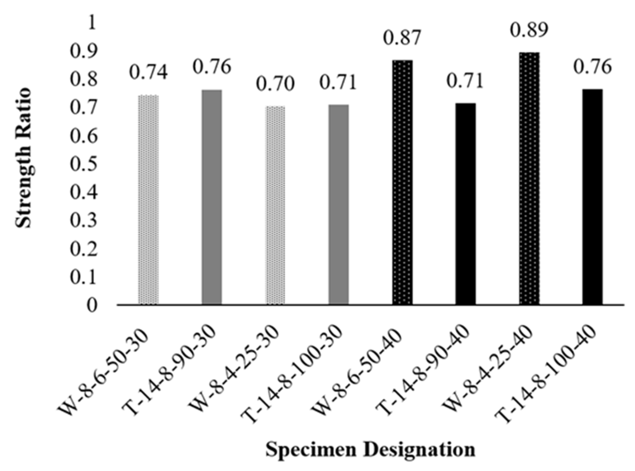
The theoretical axial compressive strength values were calculated based on the actual material properties of the tested specimens. The measured yield strengths of the steel reinforcement were 560 MPa for 8 mm diameter rebars, 520 MPa for 14 mm rebars, 560 MPa for 4 mm WWR wires, and 390 MPa for 6 mm WWR wires. The actual concrete compressive strengths were 34.3 MPa and 43.5 MPa. The resulting theoretical-to-experimental strength ratios showed average underestimations of 27% and 19% for Groups 1 and 2, respectively.
Figure 16 shows the strength ratios for all the columns based on the actual materials’ properties. The consistently conservative estimates provided by the ACI 318 code equation, particularly for columns reinforced with WWR, confirm its effectiveness in predicting the axial compressive strength for such columns without requiring modification. This ensures both practical applicability and reliability in structural design, while encouraging the broader adoption of welded wire reinforcement.
As stated earlier in the literature review part of the paper, Saatcioglu and Razvi in 1992 developed a model for confined concrete that is applicable to columns reinforced with WWR [
10]. For a symmetrical square column that is enclosed laterally by a single tie/wire around the corner bars without any cross-ties, the maximum compressive strength of the confined concrete within the core, f′
cc, can be obtained from
in which k
1 is a parameter that relates the lateral confining pressure exerted by the transverse reinforcement due to the Poisson effect to the compressive strength within the core, given by
where f
le is the effective uniform confining pressure on the concrete within the core (MPa), determined by
where k
2 is a reduction factor that accounts for the decreased lateral pressure by rectilinear ties/wires when compared to spirals in circular columns and f
l is the average uniform confining pressure (MPa), given by
where A
sp is the cross-sectional of the lateral reinforcement (mm
2), f
yh is the yield strength of the lateral reinforcement (MPa), s is the spacing of lateral reinforcement along the column length (mm), h″ is the centerline dimension of the concrete core within the cross-section (mm), and s
l is the spacing of laterally supported longitudinal reinforcement (mm).
Without consideration of the size effect, applying Saatcioglu and Razvi’s confined concrete strength equation to the core, along with the unconfined concrete strength of the cover and the actual yield strengths of the longitudinal rebars and wires, can lead to a predicted capacity of the columns at the ultimate, P
theo:
in which A
cover is the area of the concrete cover (mm
2), and A
core is the area of the concrete core (mm
2). Note that the stress in the concrete cover when the core reaches its peak strength is lower than f′
c since the strain corresponding to f′
cc is larger than that corresponding strain to f′
c.
Table 2 shows the comparison between the experimental axial capacities of the tested columns and theoretical predictions that utilize Saatcioglu and Razvi’s [
10] confined concrete model. The results indicated a consistent underestimation of 11.5% on average for the four columns in Group 1. For Group 2, the two tied columns showed an average underestimation of 12.8%, while the two WWR reinforced concrete columns showed an average overestimation of 7.0%. Overall, while the theoretical formulation that is based on the work of Saatcioglu and Razvi’s [
10] provides conservative and reliable predictions for traditionally tied columns and WWR reinforced columns made with lower-strength concrete, it is slightly less conservative for WWR reinforced columns made with a higher concrete strength.


