Article

Research on the Flexural Performance of Shield Tunnel Segments Strengthened with Fabric-Reinforced Cementitious Matrix Composite Panels

1
Key Laboratory of Urban Security and Disaster Engineering, Ministry of Education, Beijing University of Technology, Beijing 100124, China
2
Key Laboratory of Earthquake Engineering and Structural Retrofit of Beijing, Beijing University of Technology, Beijing 100124, China
3
Beijing Urban Construction Group Co., Ltd., Beijing 100089, China
4
Beijing Urban Construction Design and Development Group Co., Ltd., Beijing 100045, China
*
Author to whom correspondence should be addressed.
Buildings 2025, 15(8), 1355; https://doi.org/10.3390/buildings15081355
Submission received: 19 March 2025 / Revised: 14 April 2025 / Accepted: 18 April 2025 / Published: 18 April 2025
(This article belongs to the Special Issue Dynamic Response of Civil Engineering Structures under Seismic Loads)

Abstract

To investigate the strengthening effectiveness of Fabric-Reinforced Cementitious Matrix (FRCM) composites on shield tunnel segments, this study conducted four-point bending tests on FRCM composite panels. The influence of different cementitious matrices (engineered cementitious composite, ECC; ultra-high-performance concrete, UHPC) on the flexural behavior of FRCM panels was systematically analyzed. Numerical simulations were additionally conducted to analyze deformation behavior, damage progression, and stress variations in steel reinforcements within standard structural segments strengthened with FRCM composite panels. A parametric analysis was performed to assess the effects of cementitious matrix type, panel thickness, and carbon fiber-reinforced polymer (CFRP) grid layers on the reinforcement efficiency. The experimental results demonstrated that FRCM composite panels exhibit superior flexural performance. Specimens with UHPC matrices exhibited higher cracking stresses and enhanced flexural stiffness during the elastic phase, while those with ECC matrices demonstrated advantages in post-peak hardening behavior and energy dissipation capacity. Both matrix types achieved similar cracking strains and comparable ultimate flexural strengths. Numerical simulations revealed that FRCM strengthening significantly improves the ultimate flexural bearing capacity of segments while effectively controlling deformation. For UHPC-based FRCM reinforced segments, the ultimate bearing capacity increased with both UHPC thickness and CFRP layer quantity. In contrast, ECC-based FRCM reinforced segments exhibited capacity enhancement primarily correlated with CFRP layer addition, with negligible sensitivity to ECC thickness variations.

1. Introduction

In recent years, rapid urbanization coupled with expanding urban populations and spatial footprints has driven significant growth in urban rail transit systems. Shield tunnels, recognized as the dominant construction method for urban rail-transit tunnels, have become increasingly prevalent due to their efficiency and adaptability in densely populated environments. However, as the service time of urban metro shield tunnels increases, several cities in China are gradually experiencing a series of issues with their metro shield tunnel segments, such as water leakage, cracks, and elliptical deformation [1]. To address these tunnel issues, the current treatment methods primarily encompass structural apparent defect treatment and structural deformation treatment [2]. For apparent defects like water leakage and cracks, measures such as grouting and surface coating coverage can be employed. For structural deformation, two approaches are used: reinforcing the surrounding soil and reinforcing the inner surface of the tunnel.
As a proper means to control tunnel deformation, reinforcing the inner surface of tunnels would greatly relieve the deformation of the tunnels due to surface stacking and unloading activities, adjacent track line construction, and other such intense effects. As such, the current research is focused on the development of a cost-effective interior surface reinforcement material. Zhai et al. analyzed the full ring tunnel reinforced with steel plates under surcharge using the scaled test conducted on a full ring tunnel embedded in the existing soil environment [3]. However, their results showed that the reinforcement of the tunnel lining by steel plates increased the stiffness of the walls by 190% and the bearing capacity by 69% when compared with conditions without reinforcement. The study also showed that the timing of reinforcement helps to determine the amount of improvement in the tunnel’s ultimate bearing capacity, and the reinforcement measures should be delayed if the tunnel deformation is small. In order to analyze the reinforcement effects of channel steel and channel steel–plate combinations under adjacent foundation pit excavation conditions, Gang et al. and Wei et al. [4,5] employed numerical modeling. The findings indicated that channel steel reinforcement effectively decreases the range of fluctuation of the segment bending moments during unloading, reduces the residual bearing capacity coefficient of small segments, and significantly improves the load-bearing performance of damaged segments. The channel steel and steel plate reinforcement combination improves reinforcement effectiveness and reduces costs significantly; thus, it can be used as a better reinforcement strategy. Apart from that, other reinforcement methods, such as concrete-filled steel tubes [6], fiber-reinforced polymer (FRP) mesh [7], and steel corrugated plates [8], have also been used in the studies regarding shield tunnel inner surface reinforcement. Although existing methods effectively control tunnel deformation and enhance ultimate bearing capacity, they face limitations under high-temperature and high-moisture conditions due to inherent material constraints. Therefore, enhancing tunnel bearing capacity has been identified as another critical process in ameliorating tunnel-related issues; thus, a novel reinforcement method that elevates tunnel bearing capacity is economical and convenient, which is the need of the hour.
FRP composites have proven to be extremely durable and very strong and have therefore been commonly used for ground structure reinforcement [9]. Although epoxy resin is being used as a binder, there are certain disadvantages associated with the use of epoxy resin as a binder, such as poor resistance to high temperatures and moisture [10,11]. In order to overcome these limitations, inorganic cementitious material replaced epoxy resin, and textile-reinforced concrete (TRC) is used. However, traditional cementitious materials are brittle and have an ultimate tensile strain much less than the fracture strain of FRP mesh [12]; therefore, the full mechanical properties of the mesh are not used. To overcome these challenges, engineered cementitious composite (ECC) and ultra-high-performance concrete (UHPC) have been incorporated into TRC to develop Fabric-Reinforced Cementitious Matrix (FRCM) composites. ECC and UHPC exhibit high tensile strain capacity, fracture toughness, tensile strength, crack resistance, and durability [13,14]. As a result, FRCM composite plates not only address the shortcomings of poor crack resistance and low ductility but also fully utilize the mechanical properties of the FRP grid. Furthermore, FRCM meets the requirements for crack width control in building structure reinforcement and effectively mitigates delamination damage between the composite layer and the concrete substrate [15].
FRCM composites are outstanding performers with a very wide application potential. Zheng et al. [16] found that the flexural behavior of RC beams strengthened with BFRP-ECC could lead to great improvements in crack resistance, yield capacity, and ultimate load with effective reinforcement. Following Yang et al. [17], the post-reinforcement ultimate bearing capacity of RC beams with CFRP-ECC was studied, and it was observed that increasing the cross-sectional area of FRP grids increases the ultimate bearing capacity of RC beams. Al-Gemeel and Zhuge [18,19] evaluated the compressive behavior of circular and square columns with BFRP-ECC composite reinforcement and concluded that these materials are very effective in improving both bearing capacity and ductility. In a recent full-scale segment test, Chen et al. [20] studied the reinforcement effects of the CFRP–Polymer Cement Mortar (PCM) and of the CFRP plates over fire-damaged segments. The results showed that CFRP reinforcement enhances the tensile strength in the segment’s tensile zone, increases the sectional stiffness, and recovers the bearing capacity. CFRP-PCM enhances crack development mitigation, whereas CFRP plates only delay crack initiation until the delamination of the plates from the segment. Gao et al. [21] studied the mechanical effects of replacing C30 concrete with UHPC in tunnel secondary linings through full-scale and numerical testing. The ultimate bearing capacity of the UHPC linings increased by 27.23% under positive moment and 39.47% under negative moment, while the initial bending stiffness was improved by 21.00% and 30.06%. Liu et al. performed scaled tests of FRP-PCM layers [22], which showed the effectiveness of the FRP-PCM layers in bearing capacity, resisting tensile stress, and preventing crack propagation. FRP grid layer quantity and laying range do improve these performance parameters, but the eccentric loading decreases them. Current research on reinforcing concrete structures with FRCM composite plates predominantly focuses on above-ground building components such as beams and columns, with limited exploration and validation in tunnel engineering. The overall performance of FRCM-reinforced tunnel structures remains insufficiently verified and lacks broad consensus. The current state of the art of FRCM-reinforced tunnel structures does not demonstrate sufficient verification of overall performance, and there is no broad consensus about it. To address this gap, this study was performed to determine the influence of cement-based material composition on the flexural behavior of FRCM composite plates by performing bending tests. Numerical simulations of FRCM-reinforced shield tunnel segments were carried out afterwards to evaluate reinforcement effectiveness. These findings try to provide a scientific foundation for parameter and FRCM composite plate optimization in actual tunnel engineering applications.

2. Experimental Study on the Flexural Behavior of FRCM Composite Panels

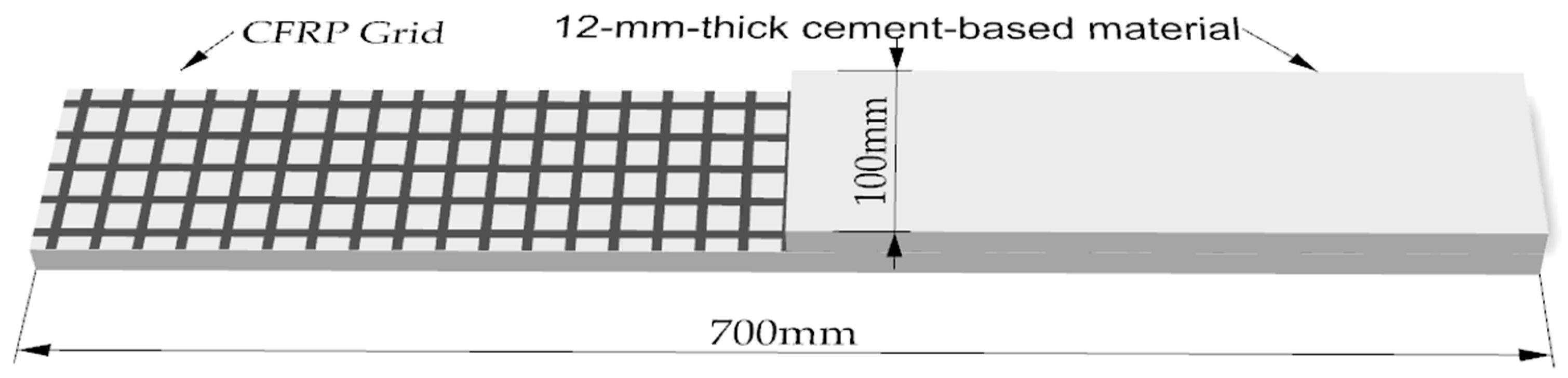
2.1. Specimen Preparation and Material Characterization

To investigate the influence of two high-performance cementitious matrices on crack-induced failure mechanisms and mechanical properties, FRCM composite panels were fabricated by integrating cement-based materials with CFRP grids. The reinforcing grid was strategically positioned at the mid-plane of the specimens. The composite panels exhibited nominal dimensions of 700 mm × 100 mm × 12 mm (length × width × thickness), with the detailed configuration and dimensional parameters illustrated in Figure 1. The purpose of configuring the specimen dimensions in this manner is to reduce the specimen size while adequately simulating its structural configuration in practical strengthening applications, thereby enhancing experimental efficiency.
The experimental program comprised two distinct test scenarios, each involving three replicate specimens, with the test variable being the cementitious matrix type of FRCM composite panels: ECC and UHPC. Specimens designated as FE series incorporated ECC matrices, while those denoted by FU series utilized UHPC matrices. The complete test matrix detailing specimen groupings and material configurations is presented in Table 1.
The experimental constituents comprised tap water; superplasticizer; ECC and UHPC admixtures manufactured by Henan Jianyan Tianzhu Building Materials Technology Co., Ltd.; short fibers; and CFRP grids supplied by Tianjin Kaben Technology Co., Ltd. The ECC matrix incorporated 12 mm polyethylene (PE) fibers with 1.5% volume fraction, while the UHPC system utilized 12 mm steel fibers at 2% volume fraction. The CFRP grid reinforcement exhibited individual fiber cross-sectional areas of 0.888 mm2 with uniform 20 mm × 20 mm mesh apertures. Detailed material proportions are tabulated in Table 2. Both ECC and UHPC followed identical mixing protocols: First, the pre-mixed dry ingredients were poured into a concrete mixer and homogenized for 3 min. Subsequently, pre-measured clean water containing a uniformly dispersed water-reducing agent was gradually introduced into the mixer over 2–3 min until achieving optimal fluidity and thorough integration of aqueous and dry components. Short fibers were then uniformly dispersed into the mixture during continuous mixing, followed by an additional 2 min of agitation to ensure homogeneous distribution. For mold preparation, a layered casting and vibration–compaction method was adopted. The mold interior was coated with a release agent to facilitate demolding. Cementitious material was poured in successive layers, with each layer interleaved with a CFRP grid until the mold was filled. Post-casting, specimens were covered with plastic sheeting and cured under standard conditions for 48 h prior to demolding. Finally, all specimens were transferred to a controlled curing chamber maintained at 20 ± 2 °C with relative humidity exceeding 95% for 28 days to ensure standardized hydration conditions.
The mechanical characterization of FRCM constituents was performed through standardized testing protocols in accordance with Chinese technical specifications: JC/T 2461-2018 [23] for high-ductility fiber-reinforced composites, T/CBMF 37-2018 [24] for ultra-high-performance concrete, and GB/T 36262-2018 [25] for structural FRP grids. The experimental program comprised three principal investigations: (1) 28-day compressive strength testing using 100 mm × 100 mm × 100 mm cubic specimens; (2) uniaxial tensile evaluation of dog-bone specimens, with ECC samples dimensioned at 320 mm × 60 mm × 13 mm and UHPC samples dimensioned at 368 mm × 100 mm × 50 mm; and (3) axial tensile testing of CFRP grids through 700 mm × 100 mm strip specimens equipped with 200 mm aluminum end-tabs for load introduction, featuring a 300 mm gauge length for strain monitoring. All test configurations and instrumentation methodologies are illustrated in Figure 2, with corresponding mechanical performance data systematically summarized in Table 3.

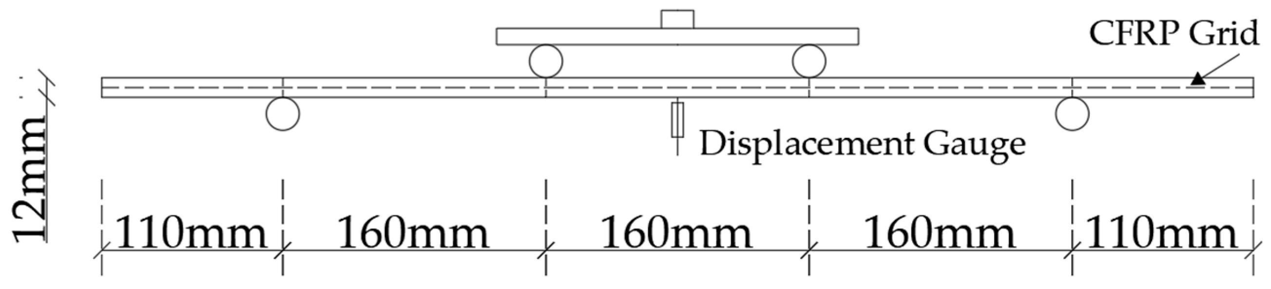
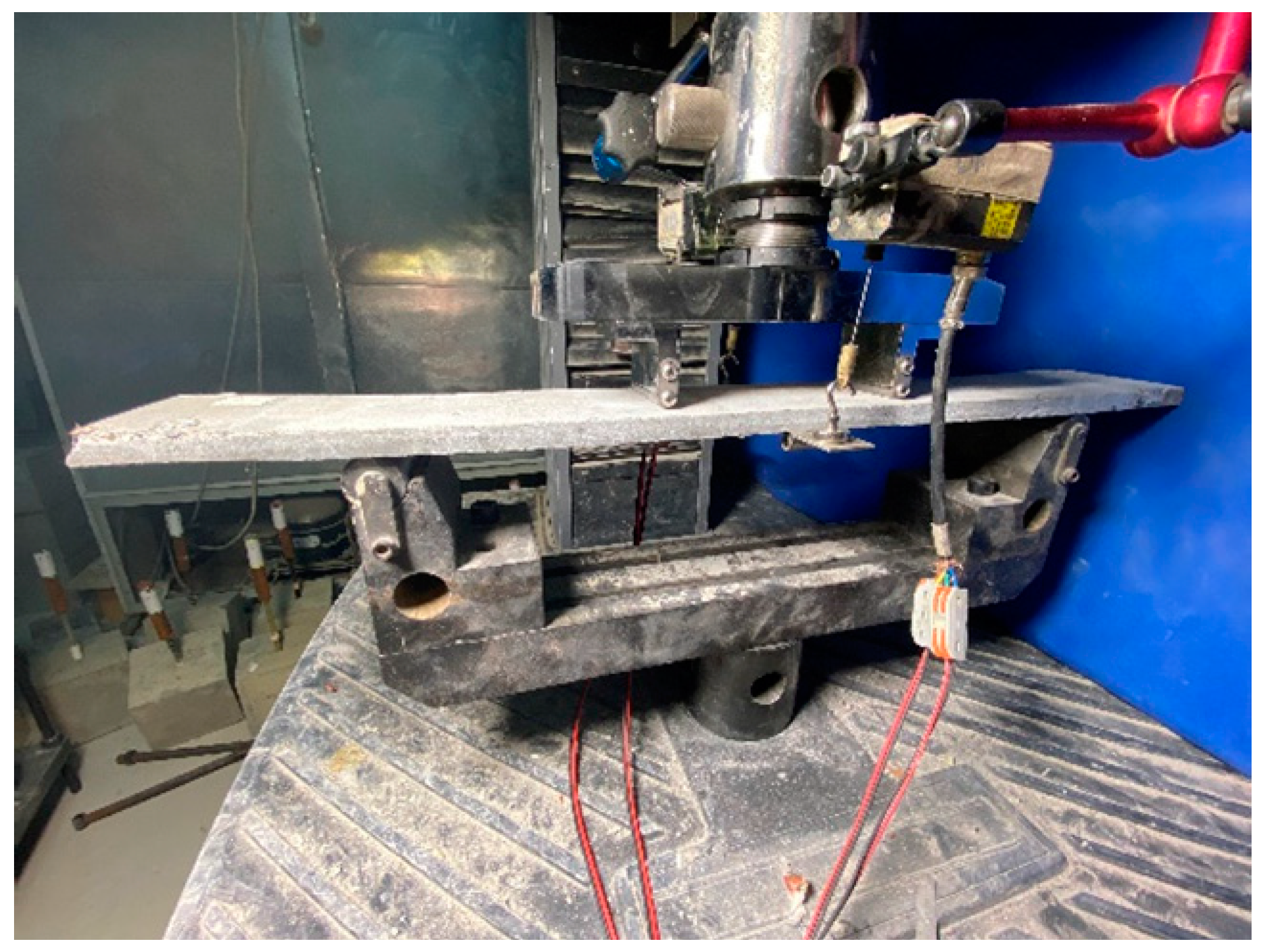
2.2. Experimental Apparatus and Loading Configuration

Four-point bending tests were conducted on FRCM composite panels using an MTS Criterion series servo-hydraulic testing system with a 30 kN load capacity. The four-point bending test follows local codes [26]. The pure bending segment was configured at 160 mm, while the support span between the bottom rollers was maintained at 480 mm to ensure proper moment distribution. Displacement-controlled loading was applied at a rate of 0.2 mm/min until failure, with real-time acquisition of load-displacement data through an integrated 50 Hz data acquisition system. The experimental loading configuration and instrumentation arrangement are schematically depicted in Figure 3, while the mechanical details of the bending fixture are presented in Figure 4.
Following specimen fixation, two linear variable differential transducers (LVDTs) were symmetrically mounted at the midspan region to monitor deflection evolution under loading. The Donghua DH3816N static stress–strain testing system was employed for synchronized acquisition of load and displacement data at a 10 Hz sampling frequency. After calibration, the testing machine underwent a preloading phase (0.1 mm/min displacement rate) until a measurable load response, followed by system zeroing. Displacement-controlled loading was then applied at 0.5 mm/min until specimen failure.
Loading was discontinued upon satisfaction of any of the following conditions: 1. When the specimen’s load-bearing capacity diminished to 75% of its peak resistance; 2. Upon attainment of 5 mm maximum crack width in the FRCM composite; or 3. When the load-displacement curve exhibited a progressive linear descending trend indicative of structural instability.

2.3. Analysis of Experimental Results

2.3.1. Failure Mechanisms of Specimens

The high-performance cementitious matrices were reinforced with centrally embedded CFRP grids, where the upper and lower cementitious layers maintained thicknesses exceeding 4 mm to ensure sufficient anchorage strength. This geometric configuration achieved effective stress transfer at the fiber–matrix interface, thereby preventing interfacial delamination failure throughout the loading history.
The FE specimens exhibit significant multiple cracking behavior. As illustrated in Figure 5a, the stress–strain response can be categorized into three distinct stages:
  • Initial Elastic Stage: During this phase, the specimen adheres to Hooke’s law, with the bending stress–strain curve displaying a linear relationship. No surface cracks are observed.
  • Post-Crack Strengthening Stage: The first crack initiates at the specimen’s base. As the load increases, additional cracks form within the pure bending zone, accompanied by progressively pronounced bending deformation. An initial fine crack widens and evolves into a dominant crack. Audible fiber fracture or pull-out events within the matrix occur during this phase.
  • Post-Peak Softening Stage: After reaching the ultimate load, the dominant crack rapidly propagates through the specimen’s cross-section, culminating in structural failure.
The stress–strain response of the FU specimen also shows the same three-stage response of the FE specimens, namely Initial Elastic, Post-Crack Strengthening, and Post-Peak Softening. Unlike FE specimens, however, FU specimens have fewer and more concentrated cracks at failure. Under increasing load, a single crack initiates at the specimen’s base, widens progressively, and dominates the failure mechanism, as seen in Figure 5b. The superior crack mitigation mechanism observed in FE specimens stems from the synergistic bridging and stress-transfer effects provided by both short fibers and continuous CFRP grids, which effectively restrain crack propagation through interfacial bond–slip interactions. This composite system facilitates stress redistribution to adjacent uncracked matrix regions, enabling the successive attainment of cracking thresholds that promote distributed microcracking patterns until crack saturation is achieved. In contrast, FU specimens demonstrated limited crack control capacity due to the steel fibers’ insufficient stress-sharing capability. Post-cracking stress concentrations in FU specimens remained below the critical threshold required to initiate secondary cracks in intact matrix zones, leading to the localized progression of a single dominant crack.

2.3.2. Stress–Strain Curve

One solution to account for dimensional variations in manufactured bending specimens is to calculate bending stress and strain perpendicular to the cross-section, which are the resultant normal stress and corresponding deformation, respectively. Equation (1) was used to obtain bending stress according to material mechanics principles for the four-point bending test, while Equation (2) was employed to find strain at midspan for the same. The stress–strain curve that results is shown in Figure 6.
σ = F l b h 2
ε = 6 d h l 2
Among these, σ is bending stress, ε is bending strain, F/2 is applied load by the testing machine at both loading points, b is the width of the FRCM specimen, h is thickness at the FRCM specimen, d is the midspan deflection, and l is the net distance between the bottom support and the specimen.
Figure 6 shows bending stress–strain curves of the composite plates with different matrix materials, and the analysis of the bending stress–strain curves shows different mechanical behaviors between composite plates with different matrix materials. FU specimens have a longer elastic stage with a higher cracking stress, corresponding to 4.43 MPa and 16.83 MPa compared to the amount measured in FE specimens. The FU specimens crack approximately four additional times when compared to the cracking strain of FE specimens, but the cracking strains are almost identical between the two. This is attributed to stress redistribution among cracks due to the presence of polyethylene (PE) fibers in the ECC, which enhances its energy absorption capacity better than the UHPC matrix that consists of smooth steel fibers with limited load-sharing capacity. Further max midspan deflection data also show these differences: FE specimens were 47.33 mm to 55.47 mm (average = 52.55 mm), and FU specimens were 16.79 mm to 17.32 mm (average = 17.00 mm). In fact, PE fibers in ECC enhanced crack propagation resistance and improved the ductility of the CFRP mesh, as they exhibited 209.1% greater deflection than FU specimens. The FE specimens exhibited superior durability under prolonged dynamic loading conditions compared to their FU counterparts, a performance enhancement attributable to the superior energy absorption capacity inherent in the ECC material system. It is, however, noted that the final bending strengths of both specimens are equal, indicating that the final bending strength of FRCM composites mainly lies in the property of the CFRP mesh. Upon the matrix cracking, the mesh of CFRP becomes the main load-bearing element.

3. Finite Element Modeling and Validation of FRCM-Strengthened Tunnel Segments

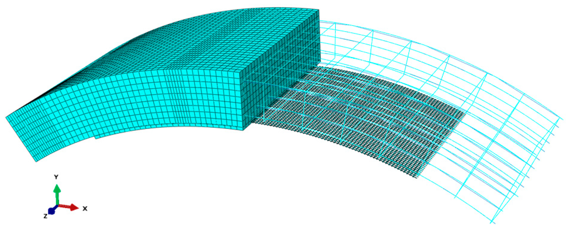
3.1. Model Configuration Overview

Using Abaqus CAE 2022 [27] finite element software and referencing full-scale bending performance tests of standard block segments from [28] and related codes [29], we developed a three-dimensional model of 6.2 m outer diameter single-track shield tunnel segments commonly used in Beijing. The segment geometry includes a central angle of 67.5°, with inner and outer arc radii of 2750 mm (arc length: 3238.8 mm) and 3100 mm (arc length: 3651.1 mm), respectively, a thickness of 350 mm, and a width of 1200 mm. The reinforcement mesh comprises longitudinal bars and stirrups: 10 HRB400 bars (18 mm diameter) on the outer arc surface, 8 HRB400 bars (20 mm diameter) on the inner arc surface, and HRB300 stirrups (10 mm diameter). Under positive bending moments, the inner side of the segment experiences tension, inducing a tightening interaction between the reinforcement layer and the segment. Based on FRCM-reinforced beam failure tests in [16], assume no delamination occurs between the FRCM composite plate and the segment. The FRCM reinforcement layer matches the segment width (1200 mm) and has a central angle of 45°, with a CFRP grid width of 1000 mm and matching arc length. For multi-layer CFRP grids, layers are uniformly distributed through the thickness of the cementitious matrix. Based on preliminary simulations identifying critical zones of segmental deformation and mesh distortion-induced numerical instabilities, targeted mesh refinement was implemented at both segment ends and load application regions. This localized grid optimization strategy effectively mitigated convergence difficulties by reducing stress concentration artifacts while maintaining computational efficiency. Figure 7 illustrates the model composition and mesh configuration.
To comprehensively evaluate the reinforcement efficacy of FRCM composite plates on tunnel segments under varying parameters, three influencing factors were analyzed: high-performance cement-based material type, reinforcement layer thickness, and CFRP mesh layer quantity. Table 4 outlines the corresponding working conditions. For instance, in the specimen label u30-2, “u” denotes UHPC, “30” indicates a 30 mm reinforcement layer thickness, and “2” signifies two CFRP mesh layers. The control group is denoted as u0/e0.

3.2. Material Characterization

The material properties of the C50 concrete and reinforcing steel for the tunnel segments were obtained from the Chinese national standard GB 50010-2010 [30]: Code for Design of Concrete Structures. The mechanical parameters of the FRCM strengthening materials—including ECC, UHPC, and CFRP grids—were derived from the experimental characterization detailed in Section 2.1.

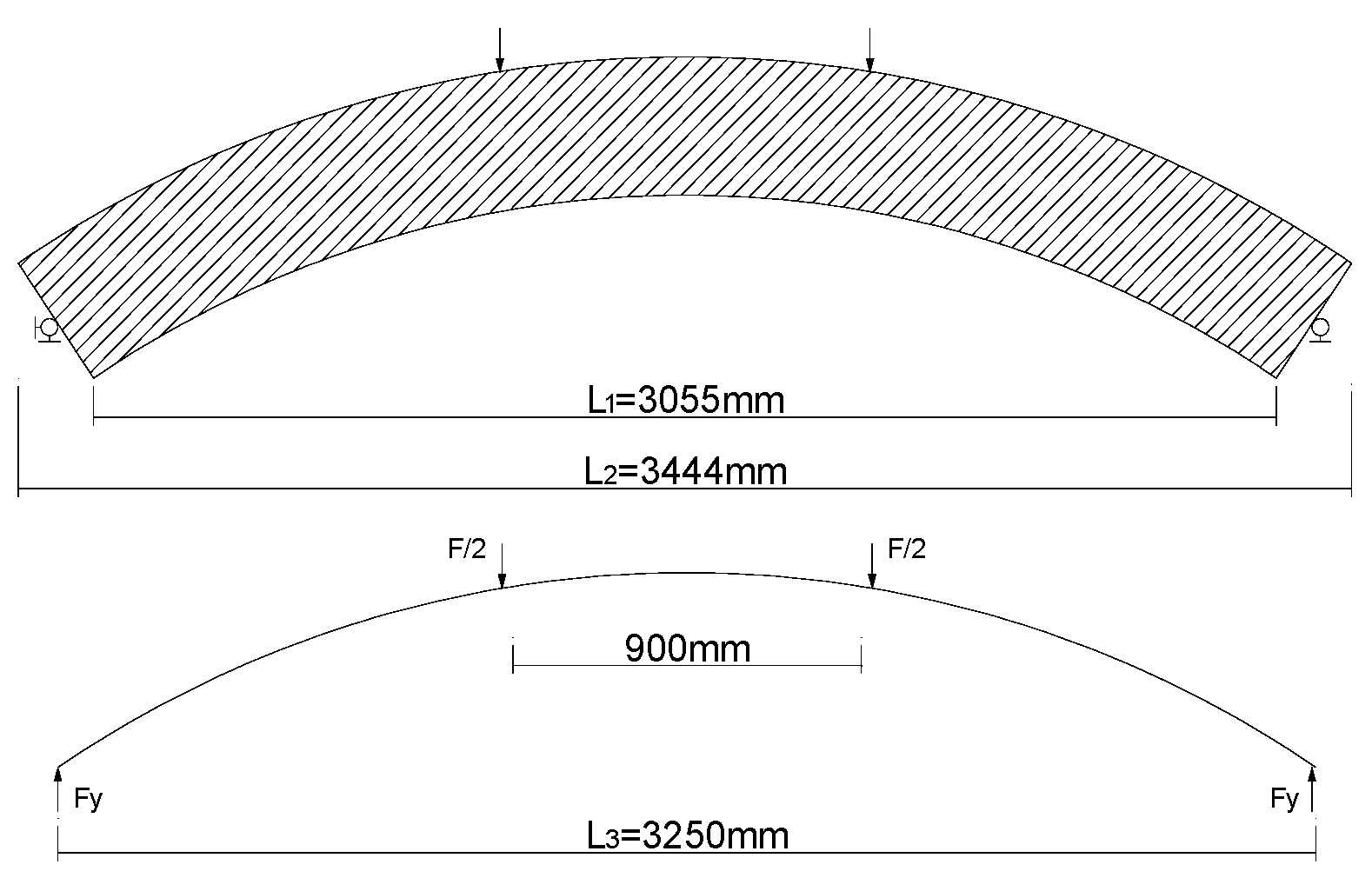
3.3. Load Application and Boundary Conditions

The vertical loading configuration, calibrated against the segment bending capacity tests documented in [28], was implemented through two reference points (RP-1 and RP-2) positioned on rigid loading plates, as schematically illustrated in Figure 8. A linearly time-dependent load function was applied, with the structural simplification employing an equivalent chord length L 3 = L 1 + L 2 2 , where L 1 and L 2 denote the 900 mm spacing between loading points. The midspan bending moment M 0 was derived from static equilibrium principles: M 0 = 1.175 F , where F represents the total applied load. Although this loading configuration does not fully replicate the in situ stress distribution of tunnel segments, the flexural testing methodology effectively characterizes the bending behavior of segments. This approach ensures structural safety margins in practical engineering applications.
The boundary conditions were established in accordance with the segment flexural capacity experiments detailed in Reference [28], employing a dual-hinge support system: one end was configured as a fixed hinge support constraining five degrees of freedom (translational displacements U1, U2, and U3 and rotational displacements UR1 and UR2), while the opposite end was modeled as a roller hinge support permitting longitudinal displacement (U1 release) while restricting four degrees of freedom (U2, U3, UR1, UR2).

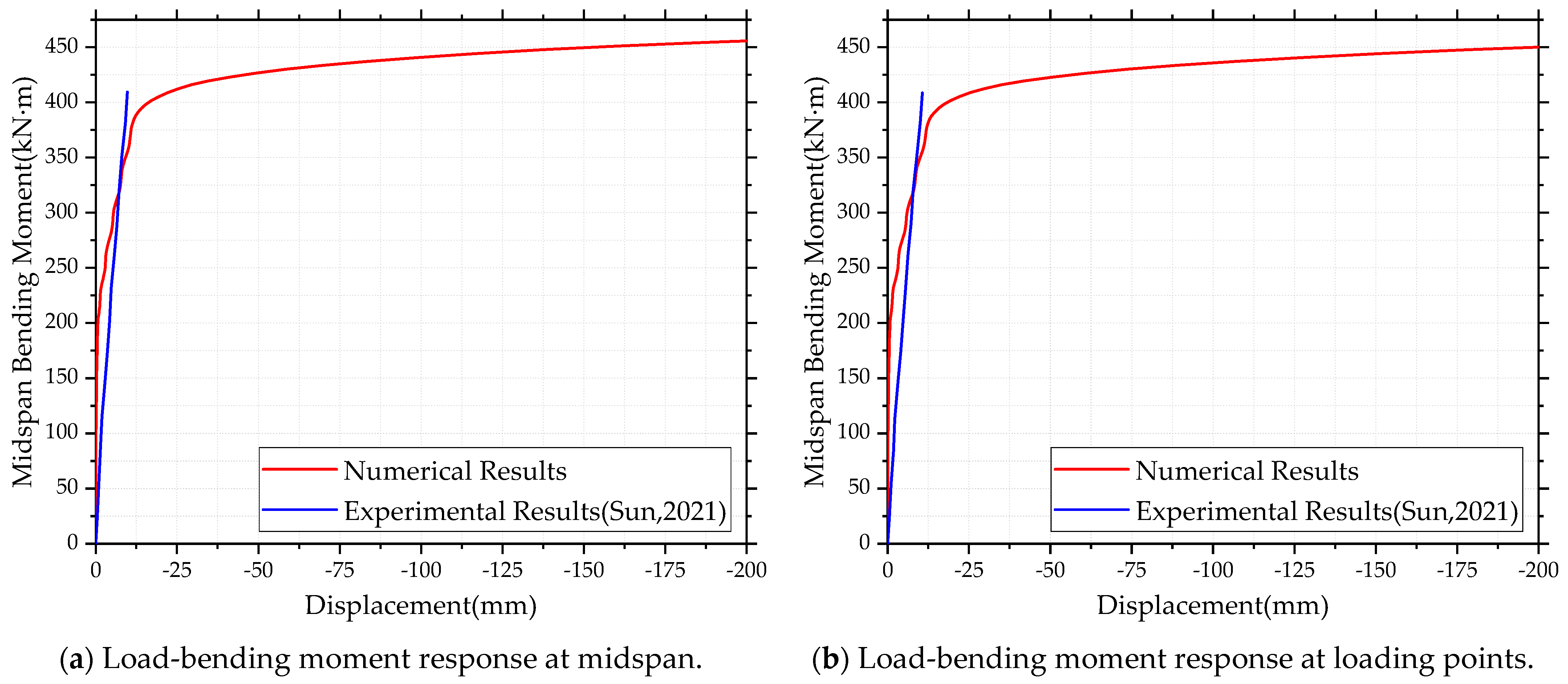
3.4. Model Validation

The midspan displacement–moment and loading-point displacement–moment curves of the unreinforced segment model were validated against experimental data from Reference [28] with reference point locations, as schematically illustrated in Figure 9, and comparative results aligning with the test setup, as schematically illustrated in Figure 10. During the linear phase, simulated curves exhibited higher stiffness than experimental results, a discrepancy stemming from model simplifications that neglected construction-induced defects and stiffness-reducing structural features, such as casting imperfections, manholes, and grouting ports. Notably, the simulated curves entered the plateau phase earlier than experimental counterparts (the limit bending moment value error is less than 4.2%), attributable to partial constraint relaxation at sliding supports in physical tests [28]. While minor deviations in absolute stiffness values exist, the model sufficiently replicates critical mechanical behavior, fulfilling the study’s primary objective of evaluating FRCM-enhanced flexural performance.

4. Performance Evaluation of FRCM-Strengthened Tunnel Segments

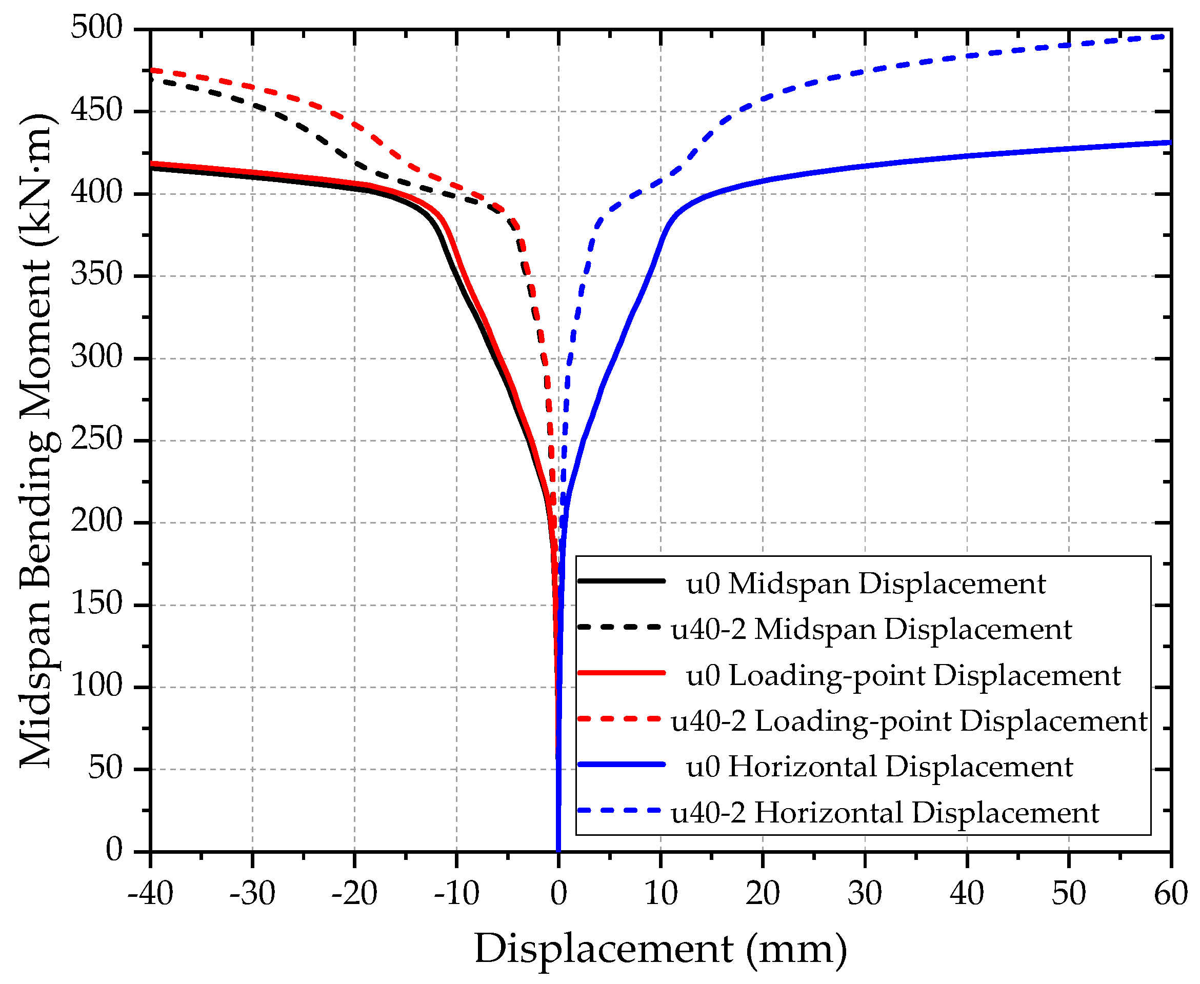
4.1. Deformation Behavior of Strengthened Segments

To systematically assess the effect of the FRCM composite plate on segment deformation, two representative specimens (designated as u0 and u40-2) were selected for a comparative analysis of their mechanical performance under load. Key deformation metrics included midspan vertical displacement, loading-point vertical displacement, and horizontal displacement, with measurement locations as illustrated in Figure 9. The displacement–moment relationships for both configurations are compared in Figure 11, revealing distinct behavioral trends.
The failure progression of unreinforced segments comprises three distinct phases: Elastic Phase, where tensile face concrete remains below its cracking strain, exhibiting high initial stiffness; Cracking Phase, initiated when tensile concrete fractures, transferring tensile stresses entirely to reinforcement and causing marked stiffness reduction and accelerated displacement growth under increasing load; and Ultimate Phase, characterized by compressive concrete crushing and reinforcement yielding, leading to flexural failure. For FRCM-strengthened segments, post-elastic behavior diverges significantly: following Phase 1, a transitional stress redistribution plateau occurs, where the CFRP grid sustains the main tensile stress. The subsequent hardening phase emerges as the CFRP grid reaches its ultimate tensile strength, transferring residual stresses to reinforcement until yielding initiates.
At the plateau phase, the FRCM-strengthened segments demonstrated a 14.58% increase in ultimate bending moment compared to unreinforced counterparts. This improvement aligns closely with the 13.1% enhancement observed in the steel plate-reinforced segments reported in [28], validating the efficacy of FRCM composites as a competitive retrofitting strategy.

4.2. Influence of FRCM Strengthening on Reinforcement Stresses

The stress distribution for unreinforced and reinforced segments in the reinforcement mesh under the midspan bending moment of 423kN·m is shown in Figure 12. The maximum tensile stress in the tensile reinforcement and the maximum compressive stress in the compressive reinforcement are at midspan and shifted toward the horizontal movable end. Tensile reinforcement prior to reinforcement was observed to have a maximum tensile stress of 507.1 MPa, which is greater than the yield strength, indicating yielding. After reinforcement, the maximum stress in tensile decreased to 15.1% (from 507.1 to 430.4 MPa) below the yield threshold. At the same time, the maximum compressive stress of the compressive reinforcement decreased by 69.3% (from 306.7 MPa to 94.0 MPa), which is an extremely large decrease compared to the tensile side. The reason is that the FRCM composite plate increases the effective cross-section height and displaces the neutral axis downwards, thus increasing the concrete compression zone. Hence, the compressive stress borne by the compressive reinforcement is diminished. This reinforcement ensures optimum stress distribution within the segment’s stress distribution and raises the midspan bending moment required to reach the reinforcement’s yield limit.

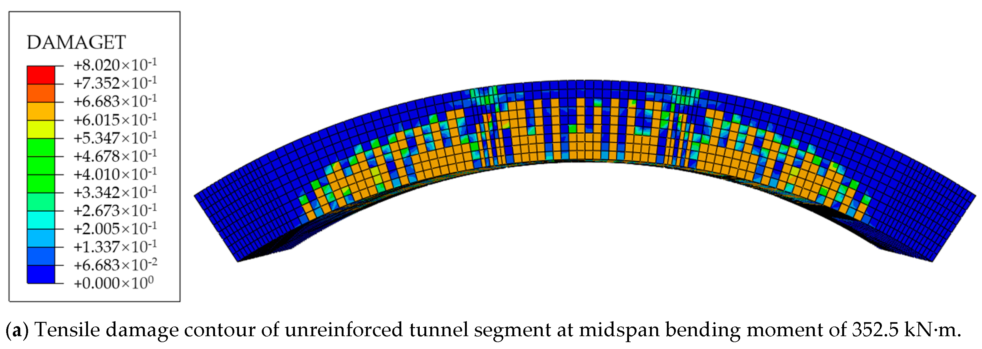
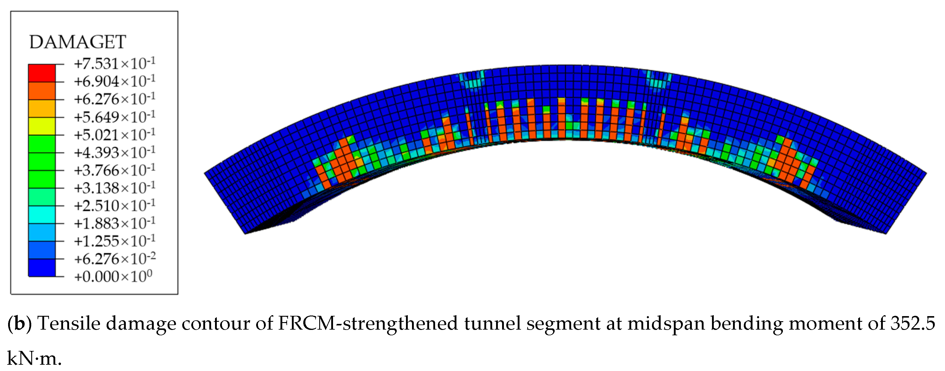
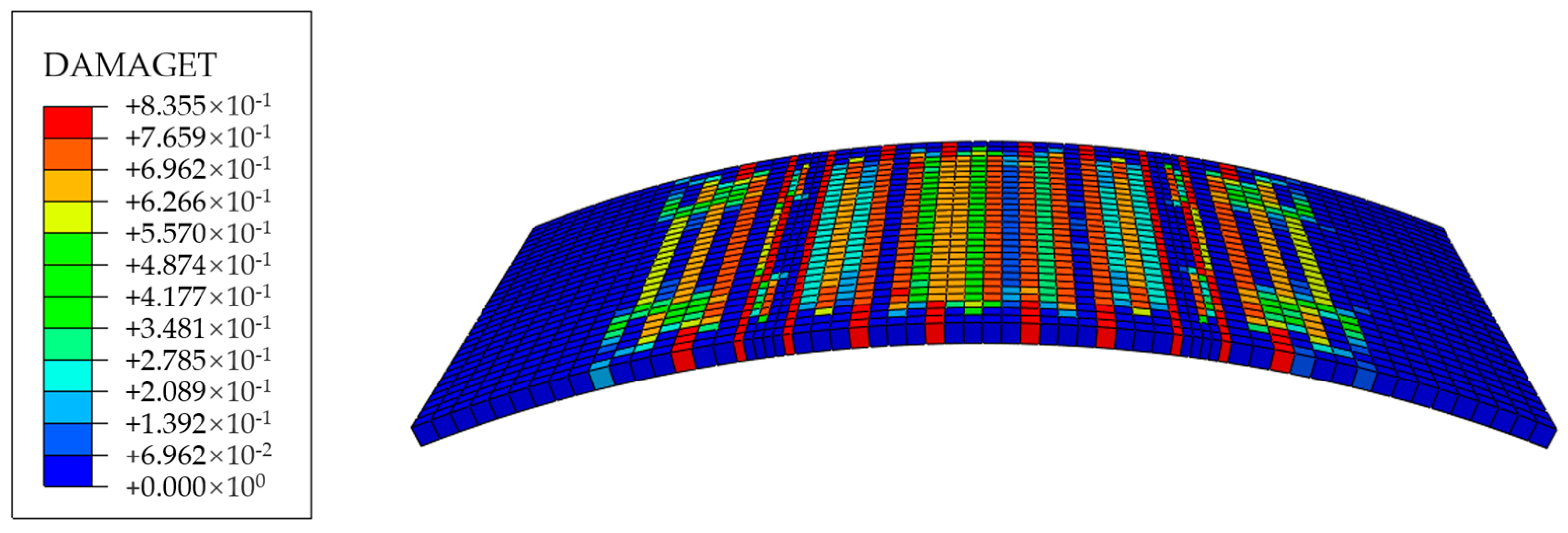
4.3. Influence of Strengthening on Segment Damage

Figure 13 presents the damage contour maps of unreinforced and FRCM-strengthened segments under a midspan bending moment of 352.5 kN·m, where a stiffness reduction coefficient (DAMAGET) of 1.0 indicates complete material failure in concrete elements. For the unreinforced segment, tensile cracking propagated extensively at the intrados, with the maximum DAMAGET reaching 0.802. In contrast, the FRCM-strengthened segment exhibited reduced crack depth and distribution, lowering the maximum DAMAGET to 0.753. Post-strengthening, tensile cracks were primarily confined between loading points, while minor cracks near the overlay edges resulted from localized stress concentrations. Figure 14 illustrates damage evolution in the FRCM cementitious matrix under the same loading condition. The FRCM composite plate significantly reduced stiffness degradation in the central reinforced zone, whereas unreinforced regions at the overlay edges showed negligible tensile participation. This result demonstrates the efficacy of FRCM composites in facilitating tensile stress redistribution and inhibiting crack propagation. The findings collectively demonstrate that FRCM composite overlays mitigate tensile crack development at the segment’s intrados, thereby enhancing structural durability by controlling damage progression.

5. Parametric Study on FRCM-Strengthened Segments

5.1. Influence of CFRP Grid Layers on Strengthening Efficacy

The influence of CFRP grid layer quantity on strengthening efficacy was evaluated through a parametric study employing UHPC and ECC matrices with a constant overlay thickness of 40 mm. Configurations with one to five CFRP grid layers were analyzed, where multi-layer grids were uniformly distributed through the cementitious matrix thickness, corresponding to interlayer spacings of 20, 13.3, 10, 8, and 6.67 mm, respectively. The midspan displacement–moment relationships for all configurations are compared in Figure 15. Key observations include the following:
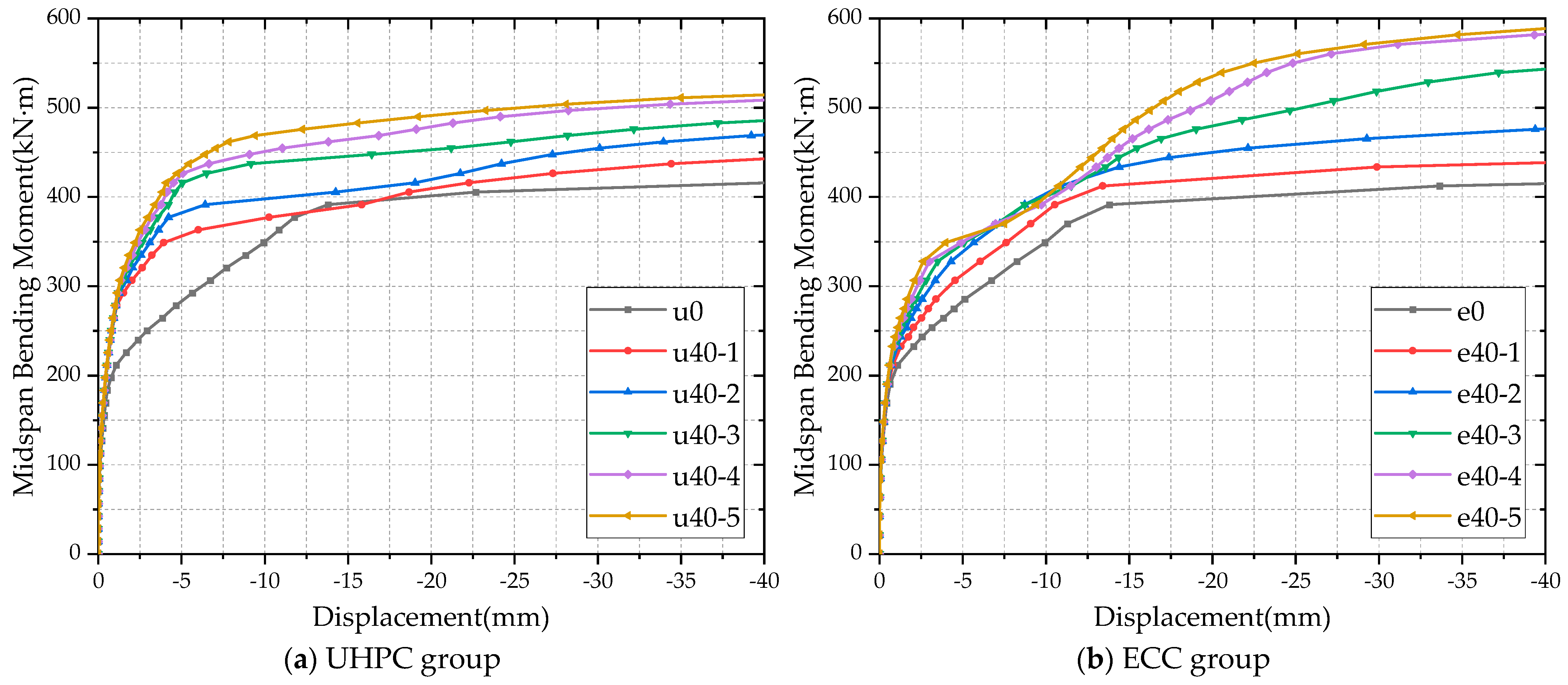
  • For low midspan bending moments, the midspan displacement for segments with FRCM composite plates is essentially the same for varying grid layers. Nevertheless, the unreinforced segments’ midspan displacement becomes steeply higher than that when the bending moment reaches 204.4 kN·m. Segments strengthened with UHPC-based FRCM composite plates show no significant displacement increase until the bending moment reaches 296 kN·m, while those with ECC-based materials experience marked displacement growth after 225.6 kN·m. This disparity indicates that UHPC-based FRCM plates provide superior control of early-stage segment deformation compared to ECC-based systems.
  • The strengthening effectiveness of FRCM composite plates increases progressively upon the inclusion of additional grid layers. Ultimate bending moment comparisons of test conditions at a midspan displacement of 15 mm between the grid layer-reinforced UHPC group (reinforced with one to five grid layers) and unreinforced segments showed increases in bending moment of 0.92%, 9.16%, 15.59%, 21.11%, and 25.59%, respectively. Also, ECC group specimens having 1–5 grid layers showed increases of 6.43%, 12.85%, 22.21%, 27.54%, and 30.61%, respectively. The analysis of changes in reinforcement efficacy shows a nonlinear relationship: reinforcement efficacy initially rises but diminishes beyond three grid layers, with the most significant improvement occurring between two and three layers.

5.2. Influence of Cementitious Matrix Thickness on Reinforcement Effectiveness

The influence of cementitious matrix thickness in FRCM composite panels was evaluated for two material configurations: UHPC and ECC, reinforced with a two-layer carbon fiber textile grid. Four distinct thicknesses—30 mm, 40 mm, 50 mm, and 60 mm—were analyzed to assess their effects on structural reinforcement. The midspan displacement–moment curves under various configurations are illustrated in Figure 16. Key observations include the following:
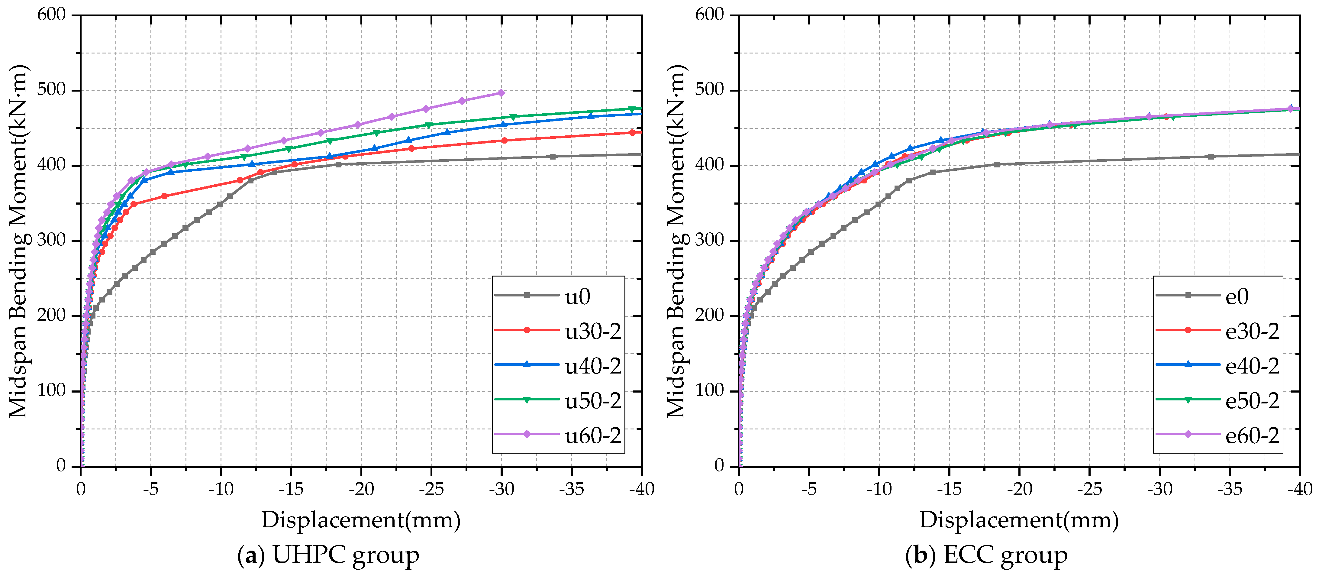
  • The UHPC group demonstrated a similar trend in reinforcement performance between specimens strengthened with varying cementitious matrix thicknesses and those with different textile grid layers. Specifically, the flexural strengthening efficiency exhibited a progressive improvement with increasing cementitious matrix thickness. Comparisons of the moment capacity at a midspan displacement of 15 mm revealed that FRCM-strengthened specimens with matrix thicknesses of 30 mm, 40 mm, 50 mm, and 60 mm achieved enhancements of 4.58%, 9.16%, 10.10%, and 14.52%, respectively, relative to the unreinforced specimen.
  • The midspan displacement–moment curves of the ECC-group strengthened specimens exhibited minimal variation across different cementitious matrix thicknesses, indicating that increasing the matrix thickness without augmenting the textile grid layers provides negligible improvement in strengthening effectiveness when ECC serves as the cementitious matrix in FRCM composites.

5.3. The Influence of Cement-Based Types on Reinforcement Effect

The influence of cementitious matrix type on FRCM composite performance was evaluated through a comparative analysis of Figure 15 and Figure 16. Key observations include the following:
  • FRCM composite panels utilizing a UHPC matrix demonstrated superior reinforcement performance at a single textile grid layer configuration. However, when the grid layer count increased, ECC-based FRCM exhibited enhanced strengthening effectiveness compared to its UHPC counterparts. This observation suggests that multi-layered textile configurations disrupt the load-transfer continuity of short fibers within UHPC matrices, while ECC, owing to its inherent ductility and strain-hardening characteristics, maintains synergistic load-sharing compatibility with the textile reinforcement.
  • When used as a reinforcement layer for UHPC-based FRCM, cementitious materials offer higher early strength and enhanced reinforcement efficacy under low-load conditions. However, under significant segment deformation, segments reinforced with ECC-based FRCM demonstrate a significantly higher load-bearing capacity compared to those reinforced with UHPC-based FRCM. Therefore, the selection of reinforcement materials should be optimized based on the deformation severity observed in tunnel engineering applications. For scenarios involving minor deformation magnitudes, UHPC-based FRCM systems are recommended, whereas ECC-based FRCM systems demonstrate superior suitability under high-deformation conditions due to their enhanced strain-hardening and multi-cracking capabilities.

6. Conclusions

This study conducts four-point bending tests on Fabric-Reinforced Cementitious Matrix (FRCM) composite plates to evaluate their failure modes and mechanical properties. Using numerical simulations, the bending resistance enhancement of shield tunnel segments reinforced with FRCM composite plates is investigated. Additionally, a parametric analysis examines the influence of FRCM composite plate properties—including cement-based material type, thickness, and grid layer configuration—on reinforcement effectiveness. The following conclusions were drawn:
  • FRCM composite plates exhibit excellent flexural performance. The stress response of FRCM specimens during four-point bending tests can be categorized into three distinct stages: Initial Elastic, Post-Crack Strengthening, and Post-Peak Softening. ECC-based FRCM specimens demonstrated a multi-crack failure mode, whereas those with a UHPC matrix exhibited fewer, more concentrated cracks. The cement type exhibited minimal influence on the flexural strength of FRCM specimens.
  • FRCM composite plates effectively reduce segment deformation, reduce reinforcement stress on shield segments, inhibit tension crack propagation, and improve the ultimate flexural capacity. These results show the great reinforcement of FRCM composite plates.
  • FRCM composite-strengthened segments strengthened by a UHPC cementitious matrix had increasing effectiveness of reinforcement with increasing textile layers and matrix thickness, while the ECC matrix-strengthened segments did so only with increasing textile layers, without significant variation with matrix thickness.
Furthermore, while the current study provides critical insights, its scope was necessarily constrained by experimental limitations. Future investigations should prioritize (a) the comprehensive characterization of FRCM composite panel-to-segment interfacial behavior, (b) the systematic evaluation of reinforcement efficacy at both joint and full-ring segment levels, particularly under complex stress states mimicking in-service tunnel conditions, and (c) the long-term creep and fatigue behavior of FRCM composites.

Author Contributions

Conceptualization, C.G. and K.Y.; methodology, Y.D.; software, K.Y.; validation, C.G. and Y.D.; formal analysis, C.G.; investigation, K.Y.; resources, J.L.; data curation, K.Y.; writing—original draft preparation, C.G.; writing—review and editing, J.L.; visualization, Y.D.; supervision, C.G.; project administration, J.W.; funding acquisition, W.L. All authors have read and agreed to the published version of the manuscript.

Funding

This research was funded by the National Key Research and Development Program of China, grant number 2022YFC3800901, and the National Natural Science Foundation of China was funded by 52278385.

Data Availability Statement

The authors declare that the data presented in this study are available upon request.

Acknowledgments

The Key Laboratory of Urban Security and Disaster Engineering of the Ministry of Education and the Beijing Key Laboratory of Seismic Engineering and Structural Diagnosis and Treatment.

Conflicts of Interest

Authors Jiulin Li and Jianlin Wang were employed by the company Beijing Urban Construction Group Co., Ltd. Authors Weidong Lu was employed by the company Beijing Urban Construction Design and Development Group Co., Ltd. The remaining authors declare that the research was conducted in the absence of any commercial or financial relationships that could be construed as a potential conflict of interest.

Abbreviations

The following abbreviations are used in this manuscript:
FRPFiber-reinforced polymer
ECCEngineered cementitious composite
UHPCUltra-high performance concrete
FRCMFabric-Reinforced Cementitious Matrix
TRCTextile-reinforced concrete

References

  1. Xu, S.; Ma, E.; Lai, J.; Yang, Y.; Liu, H.; Yang, C.; Hu, Q. Diseases failures characteristics and countermeasures of expressway tunnel of water-rich strata: A case study. Eng. Fail. Anal. 2022, 134, 106056. [Google Scholar] [CrossRef]
  2. Lou, P.; Huang, W.; Huang, X. Analysis of shield tunnels undercrossing an existing building and tunnel reinforcement measures. Appl. Sci. 2023, 13, 5729. [Google Scholar] [CrossRef]
  3. Zhai, W.; Chapman, D.; Zhang, D.; Huang, H. Experimental study on the effectiveness of strengthening over-deformed segmental tunnel lining by steel plates. Tunn. Undergr. Space Technol. 2020, 104, 103530. [Google Scholar] [CrossRef]
  4. Gang, W.; Qin, W.; Tianbao, X.; Tao, X.; Zhiguo, Z. Study on the coupling mechanism and reinforcement effect of a shield tunnel reinforced by channel steel under side pit excavation. Tunn. Undergr. Space Technol. 2024, 153, 106055. [Google Scholar] [CrossRef]
  5. Wei, G.; Wang, Q.; Zhou, X.; Feng, F.; Wang, X.; Zhang, L.; Liang, L. Experiments and numerical simulation of the reinforcement effect of channel-steel-reinforced shield tunnel segments under unloading conditions. Eur. J. Environ. Civ. Eng. 2023, 27, 4142–4164. [Google Scholar] [CrossRef]
  6. Liu, D.; Feng, X.; Duan, K.; Zuo, J.; Chen, G.; Li, M.; Chang, Y.; Xia, Z. A novel concrete-filled flange steel tubular composite supports for tunnels: A numerical perspective. Case Stud. Constr. Mater. 2024, 21, e03384. [Google Scholar] [CrossRef]
  7. Li, W.; Gang, W.; Dong, Z.; Wang, S. Experimental study on a pre-damaged scaled tunnel model strengthened with CFRP grids. J. Southeast Univ. 2017, 33, 196–202. [Google Scholar] [CrossRef]
  8. Ding, W.; Guo, Y.; Li, S.; Li, X.; Zhang, Q. Experimental research on the mechanical behavior of segmental joints of shield tunnel reinforced with a new stainless steel corrugated plate. Case Stud. Constr. Mater. 2023, 18, e02170. [Google Scholar] [CrossRef]
  9. Zhou, J.; Lin, W.; Guo, S.; Zeng, J.; Bai, Y. Behavior of FRP-confined FRP spiral reinforced concrete square columns (FCFRCs) under axial compression. J. Build. Eng. 2022, 45, 103452. [Google Scholar] [CrossRef]
  10. Papanicolaou, C.G.; Triantafillou, T.C.; Papathanasiou, M.; Karlos, K. Textile reinforced mortar (TRM) versus FRP as strengthening material of URM walls: Out-of-plane cyclic loading. Mater. Struct. 2008, 41, 143–157. [Google Scholar] [CrossRef]
  11. Raoof, S.M.; Koutas, L.N.; Bournas, D.A. Textile-reinforced mortar (TRM) versus fibre-reinforced polymers (FRP) in flexural strengthening of RC beams. Constr. Build. Mater. 2017, 151, 279–291. [Google Scholar] [CrossRef]
  12. Soranakom, C.; Mobasher, B. Geometrical and mechanical aspects of fabric bonding and pullout in cement composites. Mater. Struct. 2009, 42, 765–777. [Google Scholar] [CrossRef]
  13. Ahmad, S.; Rasul, M.; Adekunle, S.K.; Al-Dulaijan, S.U.; Maslehuddin, M.; Ali, S.I. Mechanical properties of steel fiber-reinforced UHPC mixtures exposed to elevated temperature: Effects of exposure duration and fiber content. Compos. Pt. B—Eng. 2019, 168, 291–301. [Google Scholar] [CrossRef]
  14. Lu, C.; Li, V.C.; Leung, C.K. Flaw characterization and correlation with cracking strength in Engineered Cementitious Composites (ECC). Cem. Concr. Res. 2018, 107, 64–74. [Google Scholar] [CrossRef]
  15. Keskin, S.B.; Keskin, O.K.; Anil, O.; Şahmaran, M.; Alyousif, A.; Lachemi, M.; Amleh, L.; Ashour, A.F. Self-healing capability of large-scale engineered cementitious composites beams. Compos. Pt. B—Eng. 2016, 101, 1–13. [Google Scholar] [CrossRef]
  16. Zheng, Y.; Wang, W.; Brigham, J.C. Flexural behaviour of reinforced concrete beams strengthened with a composite reinforcement layer: BFRP grid and ECC. Constr. Build. Mater. 2016, 115, 424–437. [Google Scholar] [CrossRef]
  17. Yang, X.; Gao, W.; Dai, J.; Lu, Z.; Yu, K. Flexural strengthening of RC beams with CFRP grid-reinforced ECC matrix. Compos. Struct. 2018, 189, 9–26. [Google Scholar] [CrossRef]
  18. AL-Gemeel, A.N.; Zhuge, Y. Experimental investigation of textile reinforced engineered cementitious composite (ECC) for square concrete column confinement. Constr. Build. Mater. 2018, 174, 594–602. [Google Scholar] [CrossRef]
  19. Al-Gemeel, A.N.; Zhuge, Y. Using textile reinforced engineered cementitious composite for concrete columns confinement. Compos. Struct. 2019, 210, 695–706. [Google Scholar] [CrossRef]
  20. Chen, H.; Jiang, Y.; Chen, D.; Zhang, X.; Yan, P.; Wang, B.; Lin, Q. Strengthening effect of the CFRP method on fire-damaged segments. Tunn. Undergr. Space Technol. 2024, 154, 105871. [Google Scholar] [CrossRef]
  21. Gao, B.; Chen, R.; Wu, H.; Chen, T.; Zhang, Y. Enhancement mechanism of UHPC secondary lining on the mechanical performance at joints of shield tunnels: Full-scale experiment and simulation. Tunn. Undergr. Space Technol. 2025, 157, 106282. [Google Scholar] [CrossRef]
  22. Liu, D.; Shang, Q.; Li, M.; Zuo, J.; Gao, Y.; Xu, F. Cracking behaviour of tunnel lining under bias pressure strengthened using FRP Grid-PCM method. Tunn. Undergr. Space Technol. 2022, 123, 104436. [Google Scholar] [CrossRef]
  23. JC/T 2461-2018; Standard test method for the mechanical properties of ductile fiber reinforced cementitious composites. China Architecture & Building Press: Beijing, China, 2018.
  24. T/CBMF 37-2018; Basic Properties and Test Methods of Ultra-High Performance Concrete. China Building Materials Federation, China Concrete and Cement Products Association: Beijing, China, 2018.
  25. GB/T 36262-2018; Fiber Reinforced Polymer Composite Grids for Civil Engineering. China Architecture & Building Press: Beijing, China, 2018.
  26. GB/T 50152-2012; Standard for Test Method of Concrete Structures. China Architecture & Building Press: Beijing, China, 2012.
  27. DSS (Dassault Systèmes Simulia Corp). ABAQUS Analysis User’s Manual 6.14-2; DSS: Providence, RI, USA, 2014. [Google Scholar]
  28. Sun, Q. Mechanical Performance Test and Numerical Simulation of Shield Tunnel Segments Reinforced with Internal Adhesive Steel Plates. Master’s Thesis, China University of Mining and Technology, Xuzhou, China, 2021. [Google Scholar]
  29. CJJT164-2011; Standard for Quality Inspection of Shield Tunnel Segment. China Architecture & Building Press: Beijing, China, 2011.
  30. GB 50010-2010; Code for Design of Concrete Structures. China Architecture & Building Press: Beijing, China, 2010.
Figure 1. FRCM composite panel: constituents and dimensional parameters.
Buildings 15 01355 g001
Figure 2. Experimental characterization of material properties.
Buildings 15 01355 g002
Figure 3. Schematic of test loading configuration.
Buildings 15 01355 g003
Figure 4. Schematic of experimental loading apparatus.
Buildings 15 01355 g004
Figure 5. Ultimate failure modes of FRCM four-point bending specimens.
Buildings 15 01355 g005
Figure 6. Flexural stress–strain curves of FRCM specimens under varied loading conditions.
Buildings 15 01355 g006
Figure 7. Model configuration and finite element meshing schematic.
Buildings 15 01355 g007
Figure 8. Mechanical loading schematic of tunnel segments.
Buildings 15 01355 g008
Figure 9. Deflection and displacement measurement points.
Buildings 15 01355 g009
Figure 10. Load-bending moment response at midspan and loading points [28].
Buildings 15 01355 g010
Figure 11. Comparative analysis of displacement–bending moment curves for unreinforced and strengthened tunnel segments.
Buildings 15 01355 g011
Figure 12. Stress contour plots of steel reinforcement grid pre- and post-strengthening.
Buildings 15 01355 g012
Figure 13. Tensile damage contour comparison in tunnel segments pre- and post-strengthening.
Buildings 15 01355 g013aBuildings 15 01355 g013b
Figure 14. Damage contour of cementitious matrix in strengthening layer.
Buildings 15 01355 g014
Figure 15. Midspan deflection–bending moment response of FRCM-strengthened panels with varying CFRP grid layers.
Buildings 15 01355 g015
Figure 16. Midspan deflection–bending moment behavior of FRCM-strengthened panels with varying cementitious matrix thickness.
Buildings 15 01355 g016
Table 1. FRCM composite panel flexural test: specimen grouping.
Cementitious Matrix TypeSpecimen IDSpecimen Quantity
ECCFE3
UHPCFU3
Table 2. Mix proportions of cement-based materials.
Cementitious Matrix TypeAdmixturesWaterWater-Reducing AdmixturesShort Reinforcing Fibers
ECC10.3/0.01
UHPC10.0860.010.06
Table 3. Mechanical parameters of ECC, UHPC, and CFRP grids.
Material TypeUltimate Tensile Strength (MPa)Ultimate Tensile Strain (%)Compressive Strength (MPa)Elastic Modulus (GPa)
ECC3.416.2833.61.75
UHPC7.281.31121.045.89
CFRP1345.443.50/588.79
Table 4. Experimental case configurations.
Case No.Cementitious Matrix TypeMatrix Thickness (mm)CFRP Grid LayersCase No.Cementitious Matrix TypeMatrix Thickness (mm)CFRP Grid Layers
u0////e0///
u30-2UHPC302e30-2ECC302
u40-1401e40-1401
u40-2402e40-2402
u40-3403e40-3403
u40-4404e40-4404
u40-5405e40-5405
u40-6406e40-6406
u50-2502e50-2502
u60-2602e60-2602
Disclaimer/Publisher’s Note: The statements, opinions and data contained in all publications are solely those of the individual author(s) and contributor(s) and not of MDPI and/or the editor(s). MDPI and/or the editor(s) disclaim responsibility for any injury to people or property resulting from any ideas, methods, instructions or products referred to in the content.

