
Horizontal Bearing Characteristics of Large-Diameter Rock-Socketed Rigid Pile and Flexible Pile


Abstract
1. Introduction
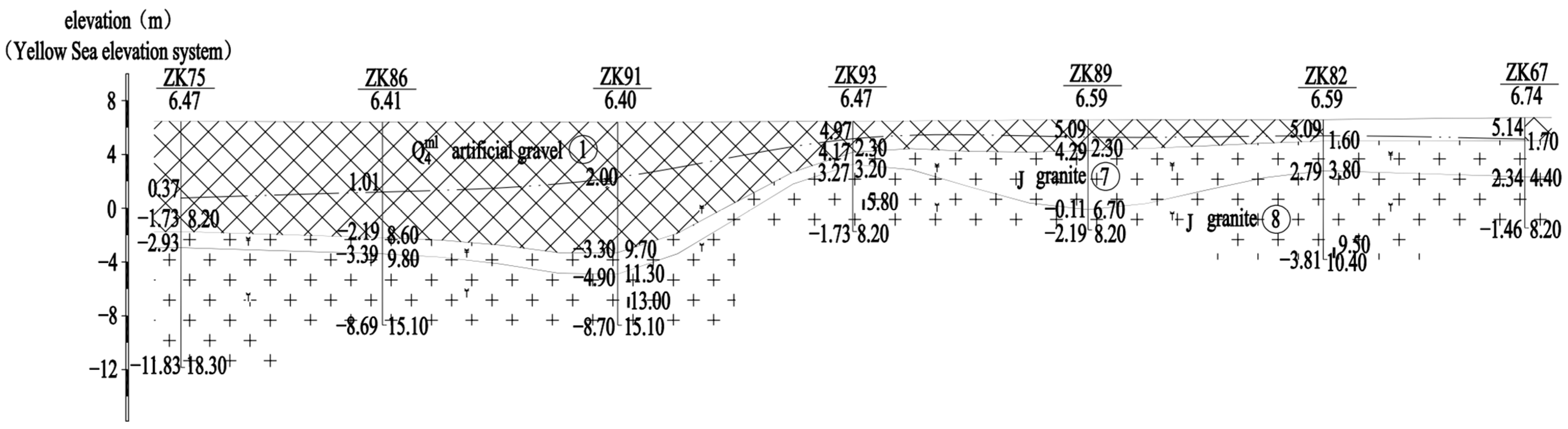
2. Test Site Conditions
3. Lateral Loading Tests on Large-Diameter Rock-Socketed Pile
3.1. Basic Parameters of the Pile
3.2. Monitoring Scheme
- (1)
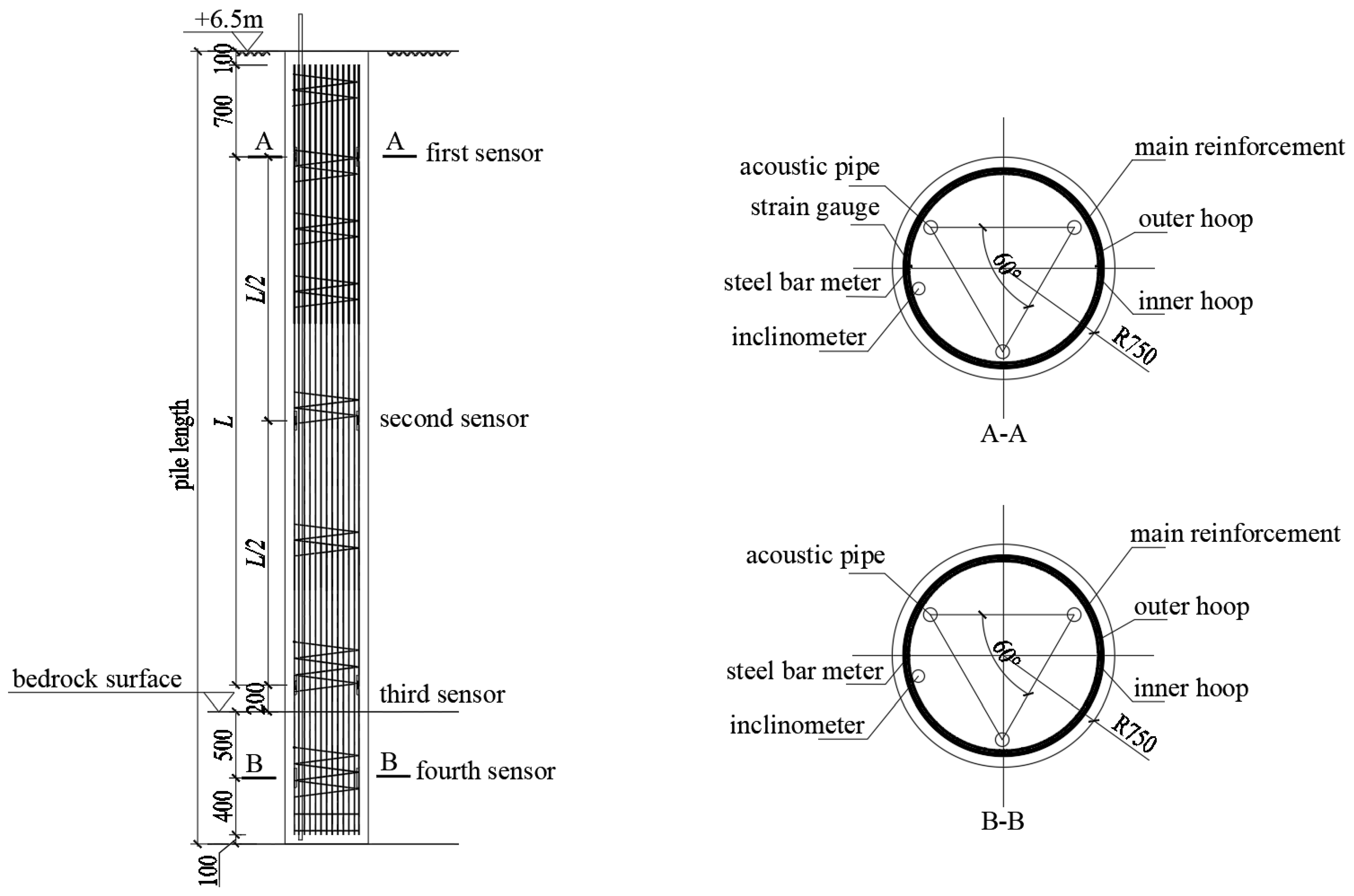
- Load and the corresponding displacement at the loading points. Two displacement sensors were arranged symmetrically on both sides of the loading point to monitor the horizontal displacement. At the positions that were 0.5 m above these two displacement sensors, another two sensors were arranged to monitor the rotation angle of the pile head. The loading points can be found in Figure 2.
- (2)
- Strain and stress of the pile body. The strain and stress sensors, which were tied inside the steel cage, were arranged on both the compression side and tension side of the pile. The layout of these sensors is shown in Figure 3.
- (3)
- Inclination of the pile body. An inclinometer was tied on the tension side of the steel cage. The bottom of the inclinometer was parallel to the pile bottom, while the top of the inclinometer was about 1 m higher than the pile head. Due to the existence of strain and stress sensors on the tension side, the inclinometer was slightly tilted towards the other side. See Figure 3 for details.
3.3. Loading Scheme
4. Results Analysis
4.1. Horizontal Bearing Capacity
4.1.1. Horizontal Critical Load
- (1)
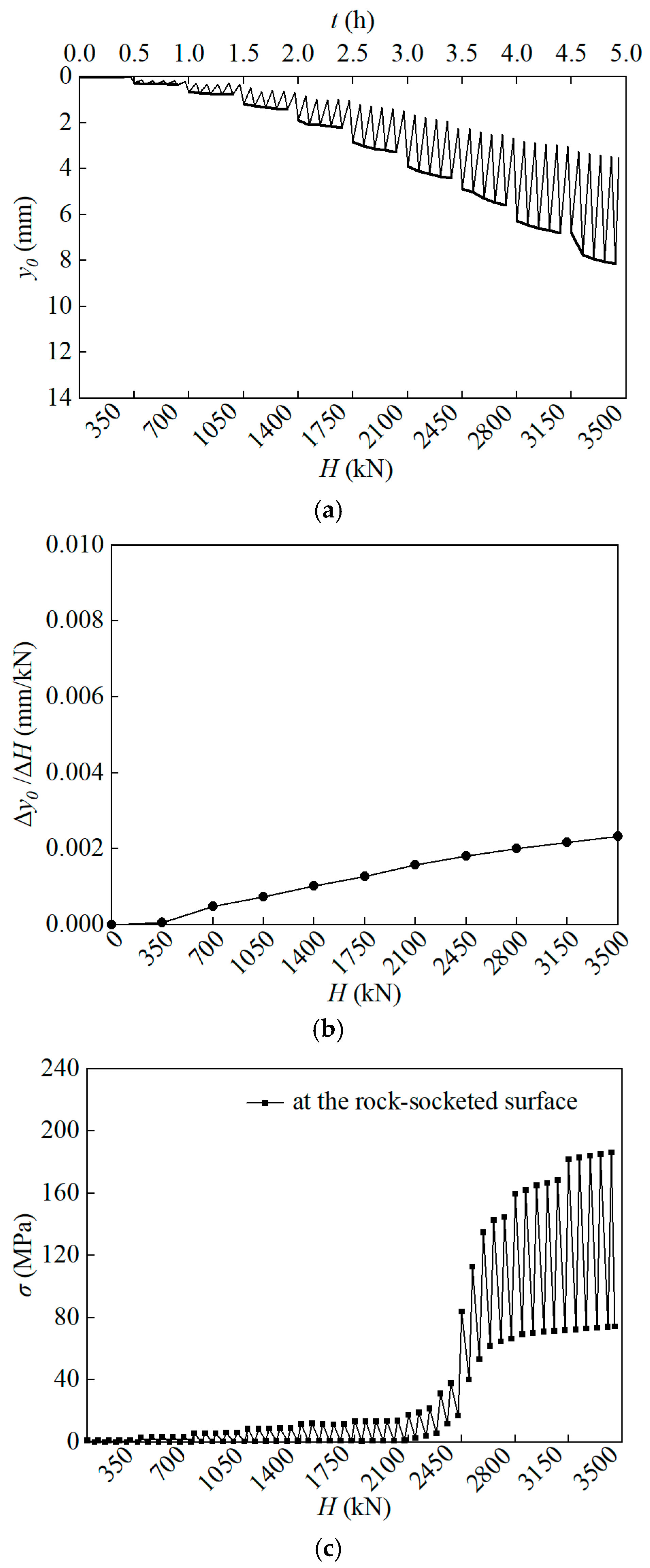
- When an inflection point appears on the H–t–y0 curve (where H is the horizontal load that is applied to the pile head, t is time and y0 is the horizontal displacement of the pile head), the previous level of the horizontal load can be taken as the horizontal critical load. H–t–y0 curves of Pile 11# and Pile 13# are shown in Figure 4a and Figure 5a, respectively. It can be seen that for Pile 11#, the horizontal displacement of the pile head remains negligible during the initial three load levels. A marked escalation in the displacement magnitude is observed from the fourth load level. Notably, when the horizontal load increases from 1750 kN to 2100 kN, the pile head exhibits a pronounced displacement. After that, the displacement grows almost linearly with an increase in the horizontal load. Therefore, according to the H–t–y0 curve of Pile 11#, the inflection point corresponds to a horizontal load of 2100 kN, so the horizontal critical load is 1750 kN. Under identical load levels, the horizontal displacement at the head of Pile 13# is significantly smaller than that of Pile 11#. With the horizontal load increasing, the displacement demonstrates a gradual but sustainable growth, and there is no obvious inflection point on the H–t–y0 curve. Hence, the horizontal critical load is supposed to be 3500 kN.
- (2)
- When the first inflection point appears on the H–∆y0/∆H curve (where ∆H and ∆y0 are increments of H and y0, respectively) or lgH–lgy0 curve, the corresponding horizontal load can also be taken as the horizontal critical load. Figure 4b and Figure 5b show the H–∆y0/∆H curves of Pile 11# and Pile 13#, respectively. The slope of this curve represents the gradient of the pile head displacement with respect to the load increment. Theoretically, when plastic deformation is generated for the first time, the growth rate of the pile head displacement accelerates significantly, resulting in a sharp increase in the slope of the H–∆y0/∆H curve. The inflection point marks the transition of the pile from elastic deformation to plastic deformation and serves as a standard for determining the horizontal critical load. This discrimination standard cross-verifies with Standard (1), thereby enhancing the accuracy and reliability of the determined results. However, from Figure 4b and Figure 5b, the inflection points on H–∆y0/∆H curves are not obvious, because these curves are basically straight. Therefore, according to this discrimination standard, the horizontal critical loads of both piles are 3500 kN.
- (3)
- The horizontal load corresponding to the first inflection point on the H–σs curve (where σs is the axial tensile stress of the pile) can be taken as the horizontal critical load. Typically, this inflection point coincides with the initial yielding of the pile body material or the onset of significant plastic deformation in the surrounding soil. During this phase, the bearing capacity of the pile undergoes a substantial alteration. When the stress on the tension side of the pile reaches the maximum, H–σs curves of Pile 11# and Pile 13# are shown in Figure 4c and Figure 5c, respectively. Because stresses at the rock-socketed surface and at the middle part of the pile body are both very large, the stress curves at these two sections are shown in the figure. The H–σs curves of Pile 11# at the rock-socketed surface and at the middle part of the pile body exhibit a consistent overall trend, and the first inflection points of these two sections correspond to the same horizontal load, i.e., 3150 kN. But for Pile 13#, the maximum tensile stress appears only at the rock-socketed surface. Compared with Pile 11#, its H–σs curve demonstrates a more apparent inflection point. The horizontal critical load of Pile 13# is determined as 2450 kN.
4.1.2. Characteristic Value of the Horizontal Bearing Capacity
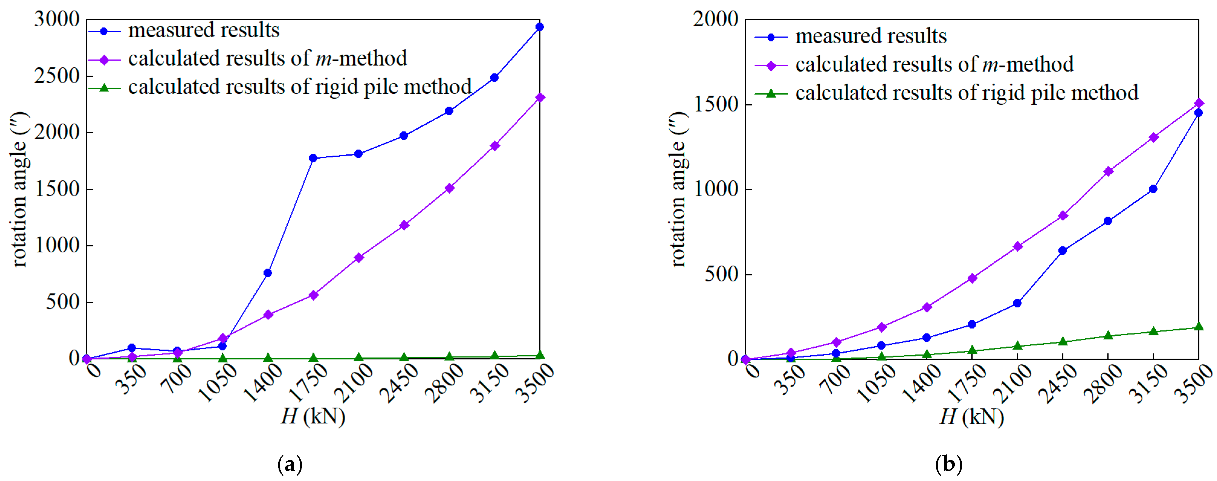
4.2. Rotation Angle of the Pile Head
4.3. Bending Moment of the Pile Body
4.3.1. Measured Results
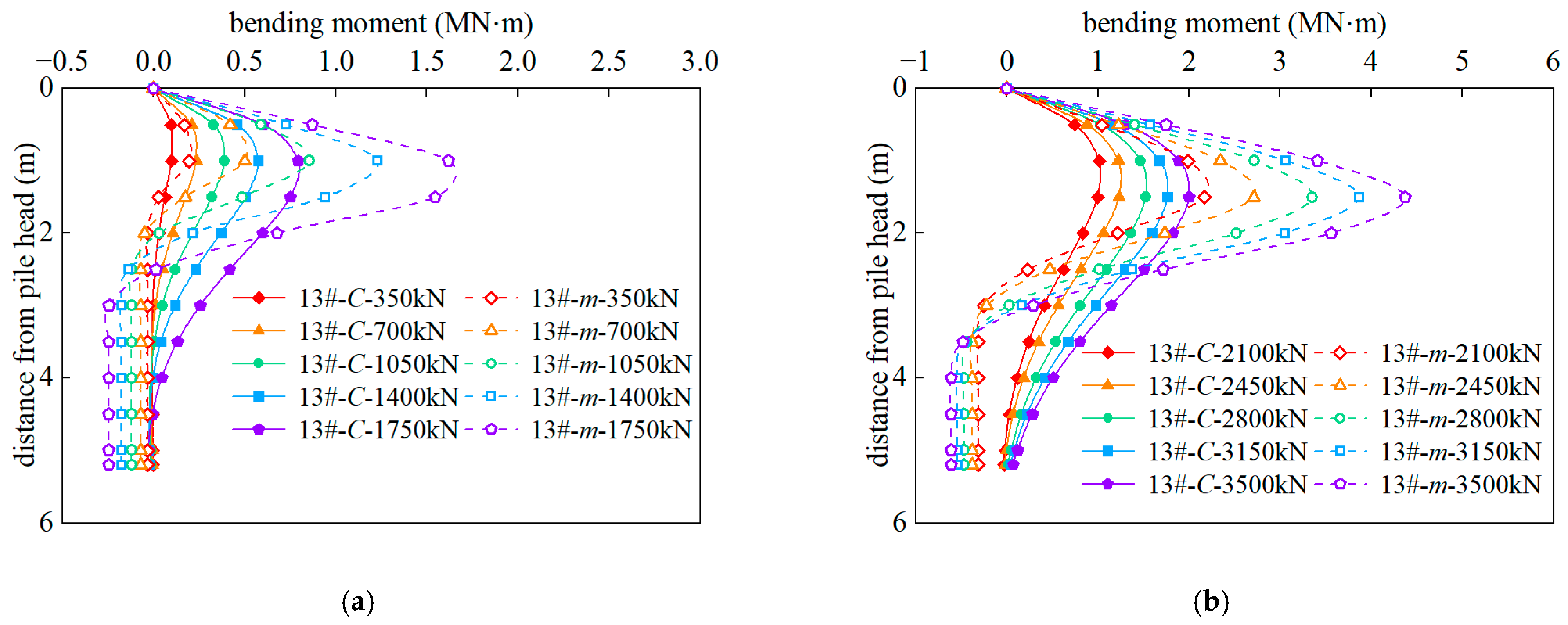
4.3.2. Calculated Results
5. Conclusions
- (1)
- According to the Technical Code for Building Pile Foundations (JGJ 94-2008) [20], if the allowable horizontal displacement of the pile head is set to be 10 mm for both rigid and flexible piles, the obtained characteristic value of the horizontal bearing capacity of the rigid pile is less than the critical load. Piles designed by this method will be in danger. Therefore, for the large-diameter rock-socketed drilled grouting pile, the horizontal bearing capacity should be comprehensively determined by considering the displacement of the pile head and the internal force of the pile body.
- (2)
- Compared with the rigid pile method, the m-method can provide a more accurate calculation for the rotation angle of the head of the large-diameter rock-socketed drilled grouting pile. Moreover, based on the m-method, the variation trend of the pile head rotation angle with the external load is more reasonable.
- (3)
- The maximum bending moment of the large-diameter rock-socketed drilled grouting pile calculated by Zhang’s method is significantly less than the measured value. The relative error is 50.3% for flexible piles and 71.2% for rigid piles. On the other side, the calculated value of the m-method is 15.9% greater than the measured value for flexible piles; therefore, this method tends to be slightly conservative. However, the m-method also underestimates the maximum bending moment of the rigid pile, which will bring some risk to the pile design.
Author Contributions
Funding
Data Availability Statement
Conflicts of Interest
References
- Gong, X.N. Pile Foundation Engineering Manual, 2nd ed.; China Architecture & Building Press: Beijing, China, 2016. [Google Scholar]
- Zeng, Z.L.; Jiang, X.L.; Liu, Z.Y. Loading test on the bearing capacity of large-diameter filling-piles. J. Hunan City Univ. (Nat. Sci.) 2010, 19, 12–16. [Google Scholar]
- Poulos, H.G. Single pile response to cyclic lateral load. J. Geotech. Eng. Div. 1982, 108, 355–375. [Google Scholar] [CrossRef]
- Alderlieste, E.A. Experimental modelling of lateral loads on large diameter mono-pile foundations in sand. Ph.D. Thesis, Delft University of Technology, Delft, The Netherlands, 2011. [Google Scholar]
- Zhu, B.; Xiong, G.; Liu, J.C.; Sun, Y.X.; Chen, R.P. Centrifuge modelling of a large-diameter single pile under lateral loads in sand. Chin. J. Geotech. Eng. 2013, 35, 1807–1815. [Google Scholar]
- Akihiro, T.; Naoya, O.; Takaaki, K.; Yukiho, K.; Satoshi, I. Centrifuge model tests on large-diameter monopiles in dense sand subjected to two-way lateral cyclic loading in short-term. Soils Found. 2022, 62, 101148. [Google Scholar]
- Sun, Y.X. Experimental and numerical studies on a laterally loaded monopile foundation of offshore wind turbine. Ph.D. Thesis, Zhejiang University, Hangzhou, China, 2016. [Google Scholar]
- Sun, Y.X.; Liu, H.T.; He, C.H.; Zhu, Y.; Zhu, B. Research on pile-soil interaction of a rigid pile subjected to cyclic loading in silt foundation. Ind. Constr. 2018, 48, 111–115. [Google Scholar]
- Wang, J.H.; Chen, J.J.; Ke, X. Characteristics of large diameter rock-socketed piles under lateral loads. Chin. J. Geotech. Eng. 2007, 29, 1194–1198. [Google Scholar]
- Sun, D.B. Experimental study on horizontal static loading tests of large-diameter drilled grouting piles in thick volcanic ash accumulation areas. Eng. Investig. 2025, 53, 13–18. [Google Scholar]
- Liu, L.; Xiao, L.; Li, X.Y.; Zhang, G.Z.; Wang, N.B.; Zhao, L.T. Research on the mechanical characteristics of large-diameter rock-socketed piles under horizontal loads. China Civ. Eng. J. 2023, 56, 44–49. [Google Scholar]
- Jiang, J.; Fu, C.Z.; Chai, W.C.; Zhang, T.; Ou, X.D. Analytical solution of lateral bearing capacity of rigid single piles based on modified shaft resisting moment. Chin. J. Rock Mech. Eng. 2022, 41, 1910–1922. [Google Scholar]
- Gawecka, K.A.; Taborda, D.M.G.; Potts, D.M.; Cui, W.; Zdravković, L.; Haji Kasri, M.S. Numerical modelling of thermo-active piles in London clay. Proc. Inst. Civ. Eng. Geotech. Eng. 2017, 170, 201–219. [Google Scholar] [CrossRef]
- Wang, H.; Fraser, B.M.; Lehane, B.M.; Wang, L.Z.; Hong, Y. Numerical investigation of the monotonic drained lateral behaviour of large diameter rigid piles in medium dense uniform sand. Géotechnique 2023, 73, 689–700. [Google Scholar] [CrossRef]
- Li, B.; Qi, W.G.; Wang, Y.F.; Gao, F.P.; Wang, S.Y. Scour-induced unloading effects on lateral response of large–diameter monopiles in dense sand. Comput. Geotech. 2024, 174, 106635. [Google Scholar]
- Liu, J.X.; Liu, Q.; Qiao, C.N.; Liu, G.X. Research on the horizontal bearing characteristics of large-diameter monopile foundations for offshore wind turbines. Energy Energy Conserv. 2022, 7, 18–20. [Google Scholar]
- Wan, Z.; Liu, Y.Y. A double volume expansion thermal-mechanical coupling constitutive model considering anisotropy. Int. J. Geomech. 2025, 25, 04025008. [Google Scholar] [CrossRef]
- Wan, Z.; Song, C.C.; Gao, W.S. Elastoplastic model of sand based on double-state parameters under complex loading conditions. Int. J. Geomech. 2021, 21, 04020256. [Google Scholar] [CrossRef]
- JTG 3363-2019; Specifications for Design of Foundation of Highway Bridges and Culverts. China Communications Press: Beijing, China, 2019.
- JGJ 94-2008; Technical Code for Building Pile Foundations. China Architecture & Building Press: Beijing, China, 2008.


| Layer No. | Name | Taking Rate of the Rock Core | Rock Quality Designation | Standard Value of the Uniaxial Compressive Strength/MPa | Hardness | Completeness |
|---|---|---|---|---|---|---|
| ⑥ | Strongly weathered granite | 75% | — | — | Extremely soft | Extremely broken |
| ⑦ | Medium weathered granite | 85% | 14% | — | Relatively hard | Broken~relatively broken |
| ⑧ | Slightly weathered granite | 98% | 70% | 67.1 | Hard | Relatively complete~complete |
| Pile No. | Diameter/mm | Total Length/m | Length Above the Rock-Socketed Surface/m | Length Below the Rock-Socketed Surface/m |
|---|---|---|---|---|
| 13# | 1500 | 5.2 | 3.2 | 2.00 |
| 11# | 1500 | 11.07 | 9.0 | 2.07 |
| Pile No. | Standard (1) | Standard (2) | Standard (3) | Final Value |
|---|---|---|---|---|
| 11# | 1750 kN | 3500 kN | 3150 kN | 1750 kN |
| 13# | 3500 kN | 3500 kN | 2450 kN | 2450 kN |
| Pile No. | When Horizontal Displacement of the Pile Head Is Equal to 6 mm | When Horizontal Displacement of the Pile Head Is Equal to 10 mm |
|---|---|---|
| 11# | 1312 kN | 1312 kN |
| 13# | 2100 kN | 2625 kN |
| Pile No. | Load/kN | ||||||||||
|---|---|---|---|---|---|---|---|---|---|---|---|
| 350 | 700 | 1050 | 1400 | 1750 | 2100 | 2450 | 2800 | 3150 | 3500 | ||
| 13# | Measured displacement/mm | 0.22 | 0.61 | 1.27 | 2.25 | 3.88 | 5.78 | 7.69 | 10.73 | 13.00 | 15.27 |
| C/MN·m−3 | 1504.88 | 896.35 | 628.00 | 435.96 | 282.00 | 211.32 | 177.43 | 136.03 | 123.24 | 114.53 | |
| m/MN·m−4 | 5481.44 | 3180.04 | 1841.32 | 1146.56 | 670.65 | 467.70 | 375.74 | 269.41 | 238.10 | 217.04 | |
| 11# | Measured displacement/mm | 0.07 | 0.17 | 0.85 | 2.34 | 3.63 | 6.38 | 8.95 | 11.97 | 15.67 | 20.15 |
| C/MN·m−3 | 6975.32 | 5360.86 | 1080.71 | 409.91 | 308.53 | 185.49 | 144.86 | 117.82 | 96.18 | 78.89 | |
| m/MN·m−4 | 36,963.1 | 26,744.4 | 3595.59 | 1074.00 | 749.38 | 396.72 | 291.78 | 224.52 | 174.40 | 136.71 | |
Disclaimer/Publisher’s Note: The statements, opinions and data contained in all publications are solely those of the individual author(s) and contributor(s) and not of MDPI and/or the editor(s). MDPI and/or the editor(s) disclaim responsibility for any injury to people or property resulting from any ideas, methods, instructions or products referred to in the content. |
© 2025 by the authors. Licensee MDPI, Basel, Switzerland. This article is an open access article distributed under the terms and conditions of the Creative Commons Attribution (CC BY) license (https://creativecommons.org/licenses/by/4.0/).
Share and Cite
Liu, L.; Xiao, L.; Liu, Y.; Zhao, M.; Jin, F.; Li, X.; Tian, Y. Horizontal Bearing Characteristics of Large-Diameter Rock-Socketed Rigid Pile and Flexible Pile. Buildings 2025, 15, 768. https://doi.org/10.3390/buildings15050768
Liu L, Xiao L, Liu Y, Zhao M, Jin F, Li X, Tian Y. Horizontal Bearing Characteristics of Large-Diameter Rock-Socketed Rigid Pile and Flexible Pile. Buildings. 2025; 15(5):768. https://doi.org/10.3390/buildings15050768
Chicago/Turabian StyleLiu, Lin, Li Xiao, Yang Liu, Mingrui Zhao, Fan Jin, Xiangyu Li, and Yu Tian. 2025. "Horizontal Bearing Characteristics of Large-Diameter Rock-Socketed Rigid Pile and Flexible Pile" Buildings 15, no. 5: 768. https://doi.org/10.3390/buildings15050768
APA StyleLiu, L., Xiao, L., Liu, Y., Zhao, M., Jin, F., Li, X., & Tian, Y. (2025). Horizontal Bearing Characteristics of Large-Diameter Rock-Socketed Rigid Pile and Flexible Pile. Buildings, 15(5), 768. https://doi.org/10.3390/buildings15050768