1. Introduction
With the growing demand for energy and the strengthening of environmental protection in all countries in the world, the promotion and application of clean energy has become an inevitable trend. As one of the clean energy sources to replace fossil energy, nuclear energy has significant potential for development. However, the primary challenge hindering the accelerated development of nuclear energy lies in enhancing its safety measures. Among these, ensuring the seismic capability of the nuclear power plant structure stands out as a crucial aspect in guaranteeing the overall safety of nuclear power facilities [
1,
2,
3].
The selection of a nuclear power plant site is of great significance due to the standard design typically adopted for nuclear power plants. Currently, the majority of the nuclear power plant sites are located on the rock foundations in the coastal regions for safety and economic reasons. However, the giant economic growth in inland areas has stimulated a large scale of development of power grid capacity, resulting in a shortage of power resources in these inland areas. In addition, the rapid development of a nuclear power will inevitably lead to the increasing shortage of site resources for nuclear power plants. Therefore, the establishment of nuclear power plants on soil foundations or even soft soil foundations has become the inevitable trend for the development of nuclear power [
4,
5,
6]. Obviously, the seismic response analysis of nuclear island plant structure under the condition of soil foundation has become a key issue to be solved urgently. In order to address the influence of the complex soil foundation on the seismic response of nuclear power plant structure, many factors, such as the dynamic interaction between structure and infinite soil, heterogeneous and nonlinear properties of soil, the diversity and complexity of site surface geometric structure, as well as the dynamic interaction among pile, soil, and structure, must be taken into consideration comprehensively.
Current research has extensively addressed these challenges, yielding significant findings. Md. Rajibul Islam [
7] conducted a comprehensive review of seismic soil–structure interaction (SSI) in nuclear power plants, highlighting that SSI has become an indispensable component in the seismic design and performance assessment of nuclear power plant (NPP) structures. Nevertheless, prevailing soil–structure interaction (SSI) models exhibit inherent limitations in characterizing nonlinear behavior and heterogeneity of near-field soils, which may compromise the reliability of computational outcomes. For example, the boundary element method and the scaled boundary finite element model [
8,
9] inherently satisfy infinite-domain boundary conditions with precision. Furthermore, these models can be coupled with the finite element seamlessly. However, when accounting for the nonlinear behavior of near-field soils, the bounded soil domain must be truncated. Consequently, the discrete degree of freedom at the interface between the generalized structure and the infinite domain becomes inherently complex, exhibiting spatiotemporal coupling effects that substantially increase storage and computational demands. The Damping Solvent Extraction Method [
10] is a novel numerical technique developed based on wave attenuation theory for bounded soils with lager artificial damping. Although this method can efficiently handle heterogeneous soil conditions, its classification as a substructure technique necessitates selecting an extensive bounded soil domain when modeling near-field soil nonlinearity. Furthermore, practical implementation is hindered by interdependencies among critical parameters—particularly between the bounded domain size and lager artificial damping ratios, which leads to research on the error of dynamic stiffness solution not being carried out in depth. In contrast, the artificial boundary model [
4,
5,
6] possesses a time-space decoupling property, simplifying numerical calculations. In addition, the model incorporates energy transmission boundaries at the external boundary of the finite element model to account for wave energy loss towards the infinite domain, enhancing calculation efficiency and facilitating nonlinear combination with near-field soil, thus has good practicability. Additionally, it is advised by the standard for seismic design of nuclear power plants GB 50267-2019 in China [
11] that the multi-transmitting boundary or viscous artificial boundary should be adopted to carry out seismic response analysis. Moreover, most existing models derive from assumptions of homogeneous infinite domains. The implementation of ground motion input mechanisms for layered or heterogeneous soil conditions remains an open research challenge.
The soil is an inherently complex medium, where large shear deformations may induce significant nonlinear effects during strong earthquakes. To accurately reappear this behavior, the most intuitive solution is to establish rational dynamic constitutive relationship. As experimental technologies are enhanced, the theoretical research on the dynamic constitutive relationship of soil is constantly developed, which correspondingly brings up multiple models. The nonlinear elastic model [
12] for yield and plastic potential surfaces was employed to accurately fit the side face of the hexagonal pyramid surface of the Mohr–Coulomb criterion. The dynamic constitutive relationship models based on Iwan model [
13] were obtained by using the distribution function, and the hysteresis curve and energy dissipation value per loading cycle were obtained. An improvement on Cam-Clay model and modified Cam-Clay model [
14] was developed based on conventional triaxial test data for normally consolidated and lightly over consolidated soils. Experimental validation confirms that the proposed model more accurately characterizes yield behavior and strength properties of intact soils than both benchmark Cam-Clay models. However, the development of a rational dynamic constitutive relationship model is challenging, owing to the impact of load type, function form, vibration frequency, soil conditions, and drainage conditions. In addition, the stability and convergence of numerical integration in nonlinear calculations are also issues which should be focused on currently. Therefore, the above models are not widely applied in the seismic safety analysis of nuclear power.
An equivalent linear method was put forward by Seed [
15,
16] in 1968, which uses the idea of linear equivalent iteration to solve the nonlinear soil problem. Since proposed, this method has been widely used in engineering owing to its unique advantages, which are primarily demonstrated in the following points: (1) clear concept, strong operability, and easy to implement; (2) the calculation parameters of different types of soil can be obtained by soil dynamic tests; (3) computationally efficient and converges quickly. The computational results of equivalent linearization are basically consistent with actual recorded results. For example, Hadjian and Tseng [
17] tested some programs using earthquake observation records from the Lotung nuclear power plant model in Taiwan, and the test results indicate that the equivalent linearization method can be used for site seismic response analysis. Due to the above significant advantages, the American standards ASCE/SEI4-16, Standard Review Plan (SRP), and standard for seismic design of nuclear power plants of China are recommended for use, which have been widely used in seismic safety analysis of actual nuclear power engineering. It is still an irreplaceable mainstream method. The equivalent linearization method is commonly adopted by professional software for seismic analysis in the field of nuclear power, such as SASSI, FLUSH, ALUSH, SuperFLUSH and CLASSI, etc. However, the above software still has some limitations to solve practical engineering projects. In particular, both CLASSI and SASSI programs are capable of conducting three-dimensional dynamics analysis. However, the calculation of degree of freedom is limited, which makes it difficult for large-scale calculation. Therefore, the mesh of the three-dimensional finite element model is relatively simpler and coarser. Furthermore, substructure method is adopted in the calculation of the above two programs. When conducting research on pile foundation treatment on non-rock foundations, it is difficult to consider the nonlinear property of soil and the interaction between pile and soil, which makes the model unsuitable for engineering application. The FLUSH and ALUSH programs mainly adopt pseudo three-dimensional dynamic analysis and have a simple modeling process as well as high calculation efficiency compared to the above real three-dimensional analysis. Additionally, these programs fit in well with the calculation results of the real three-dimensional analysis. OSHIMA Yasuhito [
18,
19] applied the pseudo-3D analysis to seismic and stability analysis of nuclear power plants and other buildings and found that the accuracy of the pseudo-3D analysis and the real 3D dynamic analysis was equivalent, but the computational efficiency was higher and easier to implement. However, contemporary nuclear island configurations demonstrate increasing complexity, as exemplified by the AP1000 design integrating containment, screen, and auxiliary buildings on a common raft foundation. Compared to the CPR1000 nuclear island plant, the AP1000 exhibits greater structural complexity with more diverse component types. Therefore, the simplification of upper nuclear island plant structure is of particular importance. In addition, the FLUSH and ALUSH programs adopt stiff base plane hypothesis, whose setting depth must be determined by sensitivity analysis, thus having a certain limitation to the absorption of wave energy of reflection wave.
The goal of this paper is to establish the pseudo three-dimensional soil–pile–structure dynamic interaction model considering the nonlinearity and heterogeneity of soil in order to better satisfy the requirements of engineering practicability of seismic resistance adaptability analysis and equivalent simplification of complex nuclear island plant structure under the condition of non-rock foundation. First of all, equivalent linear method is adopted to describe the nonlinear dynamic properties of near-field soil, and the viscous artificial boundary is used to simulate the influence of radiation damping effect of half space. With a focus on the nuclear island plant structure and pile foundation treatment, equivalent stiffness–mass simplification principle is put forward to achieve the equivalent simplification of complex NI structure and distribution of different pile foundations in order to progressively establish the pseudo three-dimensional seismic response analysis model of NI plant structure under the condition of soil and pile foundation. Then, two typical numerical examples are presented to verify the accuracy and efficiency of the proposed method. Finally, the effects of SSI, soil characteristics, and pile foundation on seismic responses of NI structures of CPR1000 and AP1000 are investigated to illustrate the reasonable engineering applicability. The design and safety evaluation of NI structures are explored to ensure their reliability and safety in seismic-prone regions and enhance the safety of nuclear energy systems worldwide.
2. Seismic Response Analysis Model of NI Structures
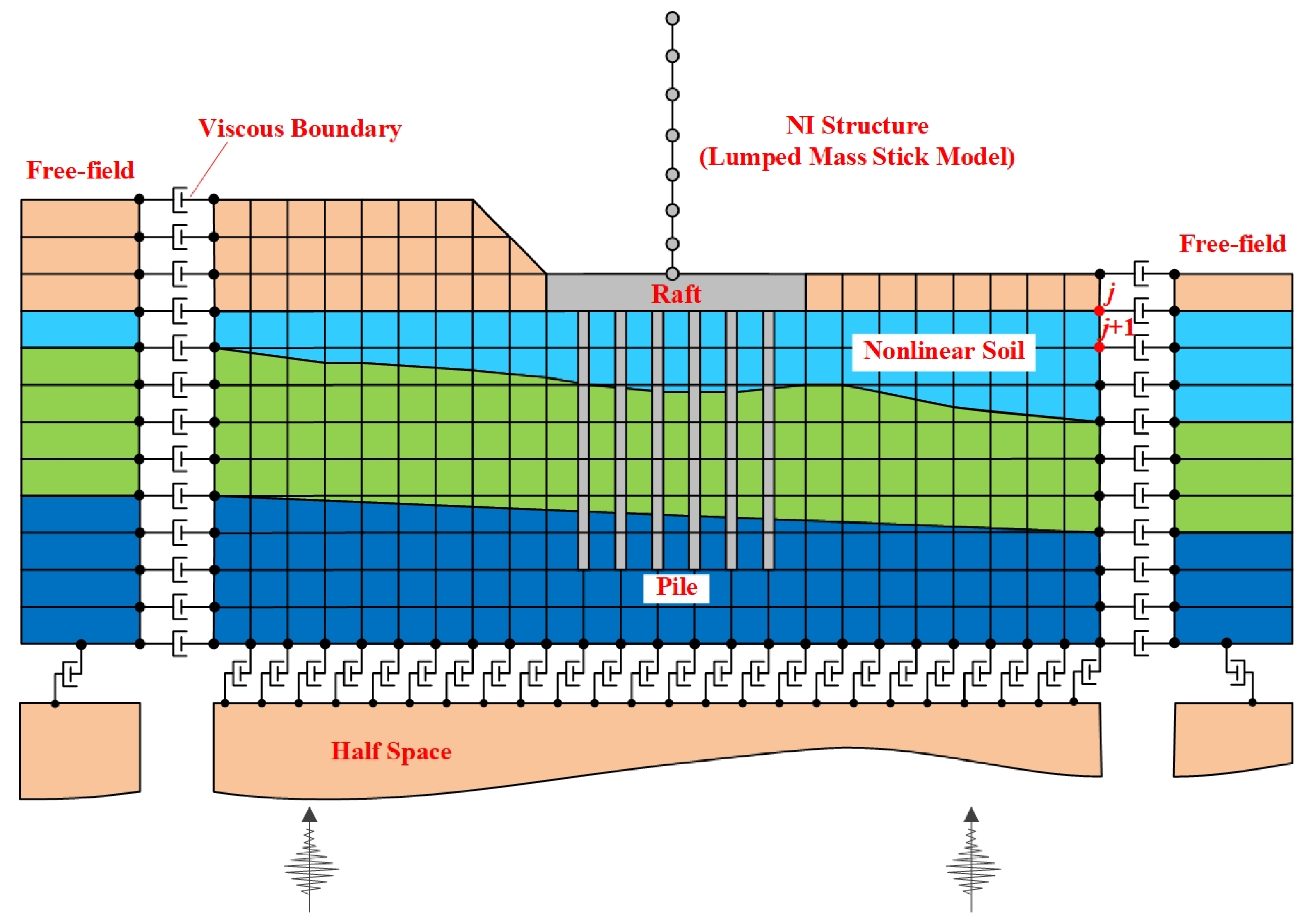
As shown in
Figure 1, the dynamic interaction analysis model between the NI structure and half space under the condition of complex soil consists of generalized structure zone and layered free-filed zone at the sides. The generalized structure zone includes NI plant structure and some near-field soil with complex lithology and non-uniformity and nonlinear characteristics, which should be considered. In addition, the nuclear island lumped mass stick model consists of the stick models of the individual buildings interconnected by rigid links. Modal analyses and seismic time history analyses are performed using this model. Plant design response spectra are developed from these analyses along with equivalent static seismic accelerations for analysis of the building structures. If treatment should be carried out on the foundation, the influence of the pile should be considered as well. The layered free-field can consider the case where the free-fields at the right-hand and left-hand sides are not identical. Each key technological function is illustrated as follows.
2.1. Equivalent Linear Method for Soil Nonlinearity
Compared to linear analysis of nuclear power plant sites on bedrock under strong earthquakes, seismic response analysis for Nuclear Island (NI) structures on non-rock foundation exhibits significantly greater complexity. However, the large shear deformations which occur in soils during strong earthquakes introduce significant nonlinear effects and some method must be introduced to take these into account. This problem has been solved by Seed and Idriss [
15] by the introduction of the equivalent linear method. According to this method, an approximate nonlinear solution can be obtained by a linear analysis provided the stiffness and damping used in the analysis are compatible with the effective shear strain amplitudes at all points of the system. Seed and Idriss [
20] have published data on strain-compatible soil properties for typical clays and sands. This data, here called material curves, can be obtained by dynamic triaxial test. This or any number of similar curves developed for specific materials may be input to program which proceeds as follows:
A set of shear modulus and damping values is estimated for each soil element of the finite element model. The system is analyzed using these properties, and the maximum shear strain time history is computed in each element of the model. From these time histories, effective shear strain amplitudes are estimated in each element, and the appropriate material curves are consulted to determine whether the strain level is compatible with the shear moduli and damping values used in the response evaluation. If incompatibility exists, the curves are interpolated to obtain updated shear moduli and damping values for the next iteration. This process repeats until convergence is achieved, typically within three to five iterations. The response from the final iteration is taken as being the nonlinear response.
The specific calculation process is shown in
Figure 2. The solution of effective shear strain
γeff is shown in the following formula:
where 0.65 is the effective shear coefficient;
γmax is the maximum unit shear strain. For the reason that the equivalent linear method adopts the principle of linear iteration, the global stiffness should be maintained the same in each iteration.
2.2. Viscous Boundary Model
Soil dynamic analysis, using the finite element method, depends on the use of appropriate boundaries to simulate the semi-infinite extent of the soil mass. The use of viscous dashpots at the boundary, to simulate the propagation of wave energy into an infinite soil mass, is widely used in seismic safety analysis of actual nuclear power engineering. As discussed above, the nonlinear dynamic property of soil is described by an equivalent linear method, which assumes the soil to maintain linear elastic mechanical properties in each iteration. Therefore, viscous boundary is adopted at the external boundary of the calculation zone.
According to the analogy, the viscous dashpots at every node of the outer boundary are needed, modelled by the damper element, as indicated in
Figure 1. The coefficients of the viscous dashpot on the nodes can be obtained from Equation (2).
where,
ρ is the mass density,
Vp is p-wave velocity of the half space, and
Vs is s-wave velocity of the half space.
a,
b are the undetermined constants and determined according to the condition that the boundary can effectively absorb the energy of the incident wave. The research shows that when
a =
b = 1, the condition that the boundary can sufficiently absorb the energy of the reflection wave at the boundary can be basically satisfied.
The surface displacement,
u(
t), of an elastic half space, loaded with a uniform stress, is identical to that of a viscous dashpot with the coefficient, when the normal and shear stress are the following:
where
σ(t) and
τ(t) are the normal and shear stress, respectively.
and
are the normal and shear surface velocity of the half space, respectively.
In the light of the above discussion, it appears that the analysis of an infinite system, including both the side and bottom of the system, can be reduced to an analysis of a finite system by the attachment of a viscous dashpot with an appropriate coefficient.
As a boundary condition at a vertical edge of the finite element system, the viscous dashpot boundary is used as an available option for the simulation of a semi-infinite horizontally layered system. Also, according to the viscous dashpot analogy, nearly perfect absorption of the energy of body waves is obtained in the range of less than 30 degrees of the incident angles of the wave front.
As shown in
Figure 1, at nodal points j and j + 1, the forces acting toward the outside of the irregular zone from layer j will be written using Equation (4).
where
hj is the control height between two adjacent nodes at the artificial boundary;
is the viscous boundary matrix;
is the scattering field speed vector imposed at the artificial boundary.
It is worth noting that the total field wave can be divided into the superposition of free field wave and scattering field wave at the artificial boundary, which can be represented as follows:
where
is the global velocity vector.
is the free field velocity vector. The free field is the earthquake input of the model.
For the input of ground motion, the observed ground motion is usually at or near the surface. To input the observed ground motion into the model, the ground motion of the bottom surface of the model needs to be calculated. In addition, for heterogeneous foundations accounting for nonlinearity, the lateral boundary response must also be derived from free-field response analysis for the application of equivalent load force, ensuring that the displacements and stresses at the artificial boundary match those in the original free field.
2.3. Soil–Pile–Structure Interaction Simulation
The equivalent stiffness–mass principle for simplification of NI structure model is to keep the global mass and global stiffness of the model before and after the simplification equivalent and seek to keep the dynamic properties of simplified plane model consistent with those of the original three-dimensional model. Additionally, the simplified model cannot totally reflect high-order regional vibrations, which are contained in the three-dimensional model. However, the low-frequency modes have a great influence on the structural response in the dynamic analysis of NI structure. Therefore, the principal vibration characteristics of two plane models equivalent are considered.
Based on above principle, the center of the raft is taken as the simplified reference point and equivalent simplification is carried out on the original entity model based on X-Z plane and Y-Z plane, respectively.
Firstly, carry out coordinate transformation on the three-dimensional model and project it onto
X-
Z plane and
Y-
Z plane, respectively. Then, modify the moment of inertia and rotational inertia for the original 3D stick elements and mass elements using Equations (7) and (8).
where ∆
d is the distance between the center of the element and its projection plane.
A is the area of the element.
Finally, the parameters in the model—such as the moment of inertia, rotational inertia, shear coefficient, mass, and cross-sectional area—are converted into equivalent values per unit width of the raft foundation in the direction perpendicular to the respective plane, thus obtaining the equivalent simplified model.
To achieve pseudo-3D finite element analysis of pile–soil dynamic interaction, while maintaining minimal changes to the global dynamic characteristics of the structure, and based on the principle of stiffness equivalence, the 3D pile group-raft foundation is simplified into the
X-
Z and
Y-
Z planes, respectively. Simplification process (taking the
X-
Z plane as an example): Project the piles along the
Y-axis direction based on the pile layout plan. Determine the number of piles n within the raft width
d along the
Y-axis direction. If adjacent piles after projection have small spacing, piles within a certain range may be combined into a single pile for calculation purposes. Then, calculate the equivalent cross-sectional area and equivalent moment of inertia of the piles in the resulting two-dimensional plane according to Equations (9) and (10), respectively.
where
S and
I are the cross section are and inertia torque of an individual pile before simplification respectively,
and
are the corresponding equivalent cross section are and equivalent inertia torque of the pile after simplification, respectively.
4. Application
This section employs seismic response analysis of NI structure of CPR1000 to investigate the effects of SSI and soil conditions. Subsequently, an engineering application case, seismic analysis of NI structure of AP1000 in China, considering varied foundation treatments, reveals dynamic response characteristics of NI structure subjected to strong seismic excitation.
4.1. Effects of SSI and Soil Condition on the Seismic Response of NI Structure of CPR1000
4.1.1. Calculation Model and Parameters
The CPR1000 reactor type represents a second-generation pressurized water reactor nuclear power technology that is predominantly utilized in China at present. The NI structure is a typical example of a pre-stressed reinforced concrete design, which comprises containment structure and internal structure, and thick raft board foundation.
Finite element models used for seismic analysis of NI structure of CPR1000 and other structural parameters on each floor are shown in
Figure 7. The material parameters of the concrete are as follows: the dynamic elastic modulus is 40.0 GPa, dynamic shear modulus is 16 GPa, Poisson’s ratio is 0.2, density is 2.5 g/cm
3, and damping ratio is 7%. The calculation parameters of in
Table 1 and the strain dependent material property curves in
Figure 3 are employed to analyze the factors affecting the seismic response of the structure.
To meet the requirements of SSI, the soil domain extends from the structural edge outwards in horizontal directions and downwards along the vertical axis, and the size of model is 139 m (length) × 47.7 m (height). As a result, this NI structure–soil interaction system is modelled with 1810 elements and 1915 nodes in all. In addition, the mesh density is satisfied with the requirement of waves propagating (4–8 nodes per wavelength).
The seismic load for the analysis was selected based on the standard design response spectrum recommended by the U.S. Nuclear Regulatory Commission (NRC), specifically the RG1.60 response spectrum [
24]. The RG1.60 design response spectra and time history sealed to 1g horizontal ground acceleration can be found in reference [
25]. In the following computational analysis, the total duration of the ground motion was 28 s with a time step of 0.01 s, the horizontal peak ground acceleration (PGA) was set to 0.540 m/s
2, and the vertical PGA is 0.540 m/s
2.
4.1.2. Analysis of Results
To investigate the variation patterns of seismic responses in NI structure under fixed, elastic and nonlinear base conditions, three numerical cases are carried out for comparison, and the Case ID is F-Linear, V-Linear, and V-Nonlinear, respectively. For the F-Linear condition, the nodes of the foundation boundary are restrained to move in all degrees of freedom and soil is linearly elastic. For the V-Linear condition, the viscous boundary model is adopted, and soil is linearly elastic. For the V-Nonlinear condition, the viscous boundary model is adopted, and soil nonlinearity is described by equivalent linear method.
The highest elevations of the containment and internal structure (Nodes 8 and 12) were selected as critical response monitoring points, and acceleration response spectra under three numerical cases with a damping ratio of 5% were compared and analyzed. Since the seismic response value at the highest elevations is larger than that of other nodes, the selected monitoring points have the characteristics of representativeness.
Comparison of floor response spectrum at top nodes of the NI structure are illustrated in
Figure 8.
Table 3 shows the comparison of the peak acceleration of the response spectrum, the corresponding peak frequency and the maximum displacement of the two nodes under three different conditions.
By comparing the effect of SSI effect under the F-Linear case and V-Linear case, it can be seen from
Figure 8 that the viscous boundary model simulating radiation damping significantly reduces the acceleration response relative to the fixed base model. Although the trend of the floor response spectrum curves is basically similar, the values are reduced overall. The maximum reduction in the horizontal direction is approximately 39%, and the maximum reduction in the vertical direction is approximately 55%. Additionally,
Table 3 similarly indicates that while F-Linear case and V-Linear case exhibit nearly identical peak frequencies, their peak accelerations differ significantly. This discrepancy arises because the fixed base model has inherent limitations in simulating semi-infinite spaces within confined foundation domains. Unlike the viscous boundary model, it cannot effectively absorb scattering wave energy, leading to overestimated computational results. Conversely, the viscous boundary absorbs dissipated energy, thereby reducing structural responses.
Considering the effect of soil nonlinearity, the variation law of acceleration response spectrum is basically the same in the horizontal direction under the V-Linear case and V-Nonlinear case. However, the amplitudes differ significantly. Specifically, in the horizontal direction under V-Nonlinear conditions, the peak frequency in the low-frequency region shifts toward lower frequencies, and the amplitudes exhibit varying degrees of reduction in V-Nonlinear case. This behavior arises because the consideration of nonlinear effects in the equivalent linear method model leads to a decrease in shear modulus and an increase in damping ratio as the equivalent shear strain amplifies. Consequently, the fundamental frequency of the foundation decreases, resulting in increased acceleration amplitudes of the nuclear island structure within lower frequency ranges while simultaneously dampening unmodified spectral peaks. In the vertical direction, the acceleration response spectrum variation pattern is broadly analogous to the horizontal direction, though the associated amplitude changes are less pronounced.
A comparison between F-Linear case and V-Nonlinear case reveals that when both the viscous boundary model and soil nonlinearity are considered concurrently, the acceleration response spectrum amplitudes undergo significant reductions. The maximum reduction reaches approximately 81% (about 7.1 m/s
2), observed at Node 8 in the x-direction. Additionally, the peak acceleration frequencies shift toward lower frequencies. Furthermore, displacement values at typical locations (Nodes 8 and 12) in
Table 3 exhibit trends consistent with the structural acceleration response spectra: displacements are largest in F-Linear case and decrease monotonically across V-Linear case and V-Nonlinear case. This further demonstrates the mitigating effect of accounting for radiation damping and soil nonlinearity on structural dynamic responses. Moreover, horizontal displacements substantially exceed vertical displacements, indicating that the structure is predominantly subjected to seismic shear forces in the horizontal direction.
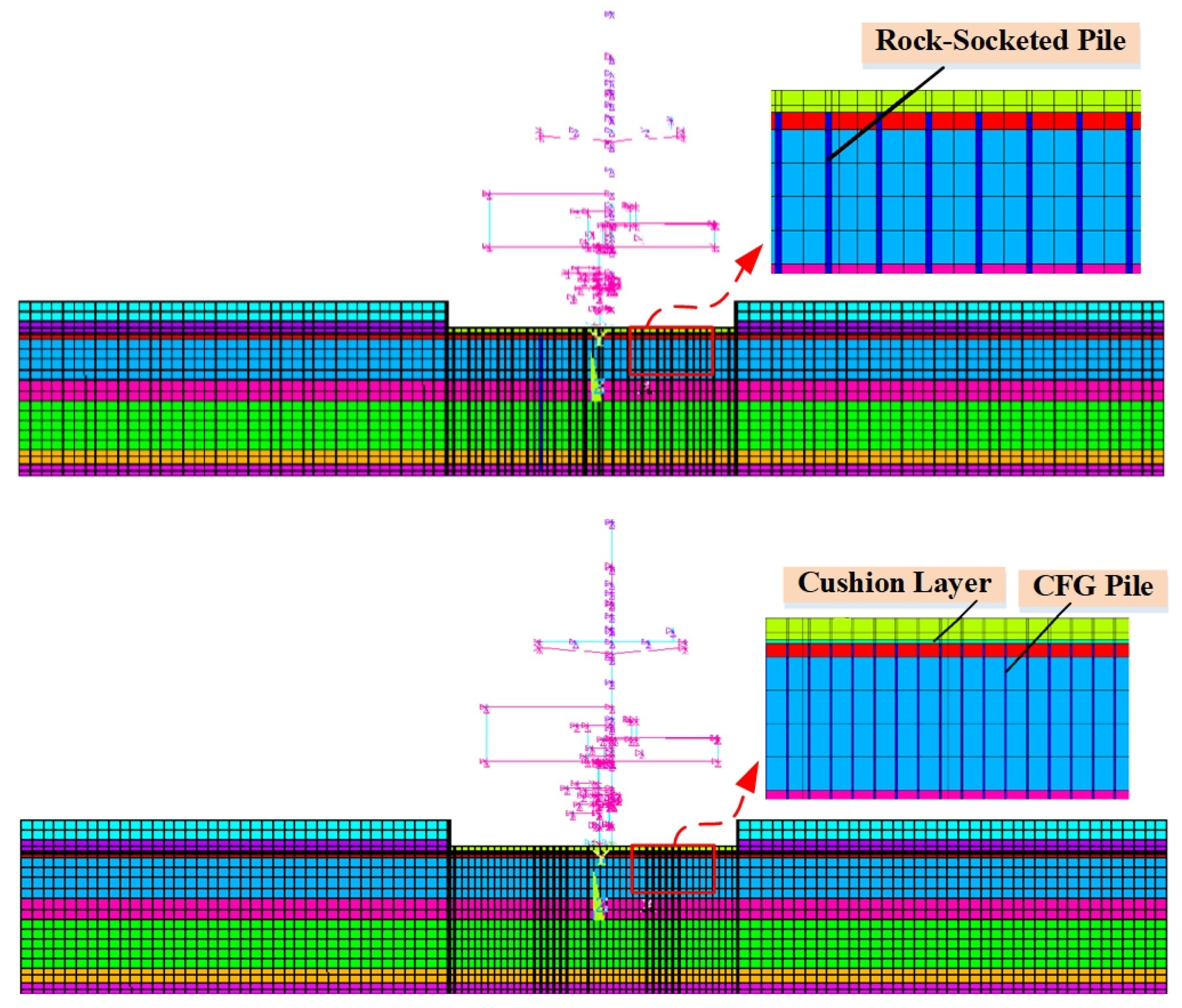
4.2. Effects of Pile Foundation on the Seismic Response of NI Structure of AP1000
The site conditions described in
Section 3.1 are those of an actual AP1000 nuclear power plant site in China. However, the total designed load on the upper structure of NI is 1243.1 MN while the pressure on the bottom of raft board is 379.13 kPa. The silty sand at the design elevation of the nuclear island foundation base exhibits inadequate bearing capacity based on calculations. Therefore, to meet the foundation adaptability requirements for the NI structures, a comparative study of foundation treatment schemes must be conducted through integrated consideration of both bearing capacity and seismic response.
Based on the actual engineering conditions described above, this paper proposes two foundation treatment schemes: rock-socketed piles and CFG (Cement-Fly ash-Gravel) piles. The pile layout for each scheme is illustrated in
Figure 9. The pile parameters are listed in
Table 4.
4.2.1. Calculation Model and Parameters
Based on the proposed method of pile–soil dynamic interaction, the pseudo-analysis of AP1000 is carried out based on the viscous boundary. Finite element models of different pile foundation used for seismic analysis of dynamic interaction model are shown in
Figure 10. The calculation parameters of site in
Table 1 and the strain dependent material property curves in
Figure 3 are also employed to analyze the factors affecting the seismic response of the structure.
Figure 11 presents the input acceleration time history curve obtained from the seismic safety evaluation report at ground surface of the NPP site, with a total duration of 40.0 s and a time step of 0.01 s. The PGA in the horizontal direction is 0.287 g, and the PGA in the vertical direction is 0.264 g.
4.2.2. Analysis of Results
To explore the dynamic response characteristics of NI structure of AP1000 under varied foundation treatments conditions, three numerical cases are carried out for comparison, and the Case ID is OF, RS Pile, and CFG Pile, respectively. For the OF condition, the foundation remains in its original state without any treatment. For the RS Pile condition, the foundation treatment scheme adopts rock-socketed piles. For the CFG Pile condition, the CFG Pile is adopted. Additionally, the viscous boundary and soil nonlinearity are all used in the above cases.
Acceleration Response Analysis
The distribution of maximum acceleration of foundation under different cases is illustrated in
Figure 12. From the point of view of distribution, the maximum acceleration distribution under the three foundation conditions is generally consistent. The acceleration amplitude at the foundation below the structure becomes relatively small due to the increased stiffness, while the acceleration amplitude of the soil on either side increases due to the effect of scattered waves. The acceleration amplitude near the bottom of the model generally decreases gradually with depth, due to the wave-absorbing effect of the viscous boundary. From the point of view of acceleration value, the vertical maximum acceleration below the NI structure under the OF case reaches 2.4 m/s
2, while the acceleration value under RS Pile and CFG Pile cases decrease to some extent to 2.3 m/s
2, 2.3 m/s
2, respectively. For the soil on sides of the NI structure, the vertical maximum acceleration under the OF case reaches 4.6 m/s
2, while the acceleration value under RS Pile and CFG Pile cases decrease to some extent to 3.3 m/s
2, 3.4 m/s
2, respectively. It is not difficult to see that the effect of rock-socketed piles is slightly better than that of CFG piles.
Displacement Response Analysis
Displacement of foundation serves as one of the key indicators for evaluating the effectiveness of ground improvement. To this end, this paper conducts a comparative analysis of displacement response results under different cases, as illustrated in
Figure 13. It can be readily observed from
Figure 13 that both the RS Pile and CFG Pile cases exhibit reduced lateral displacements at the foundation base compared to the OF case in the horizontal direction. Notably, the maximum relative displacement beneath the raft foundation in untreated ground exceeds 50 mm, whereas the rock-socketed pile foundation reduces to below 40 mm. Furthermore, in the vertical direction, the maximum relative displacement beneath the raft foundation of untreated soil measures 5.5 mm, while at the same location of the improved rock-socketed pile foundation, it decreases to approximately 1.8 mm, demonstrating significant improvement.
Floor Response Spectra Analysis
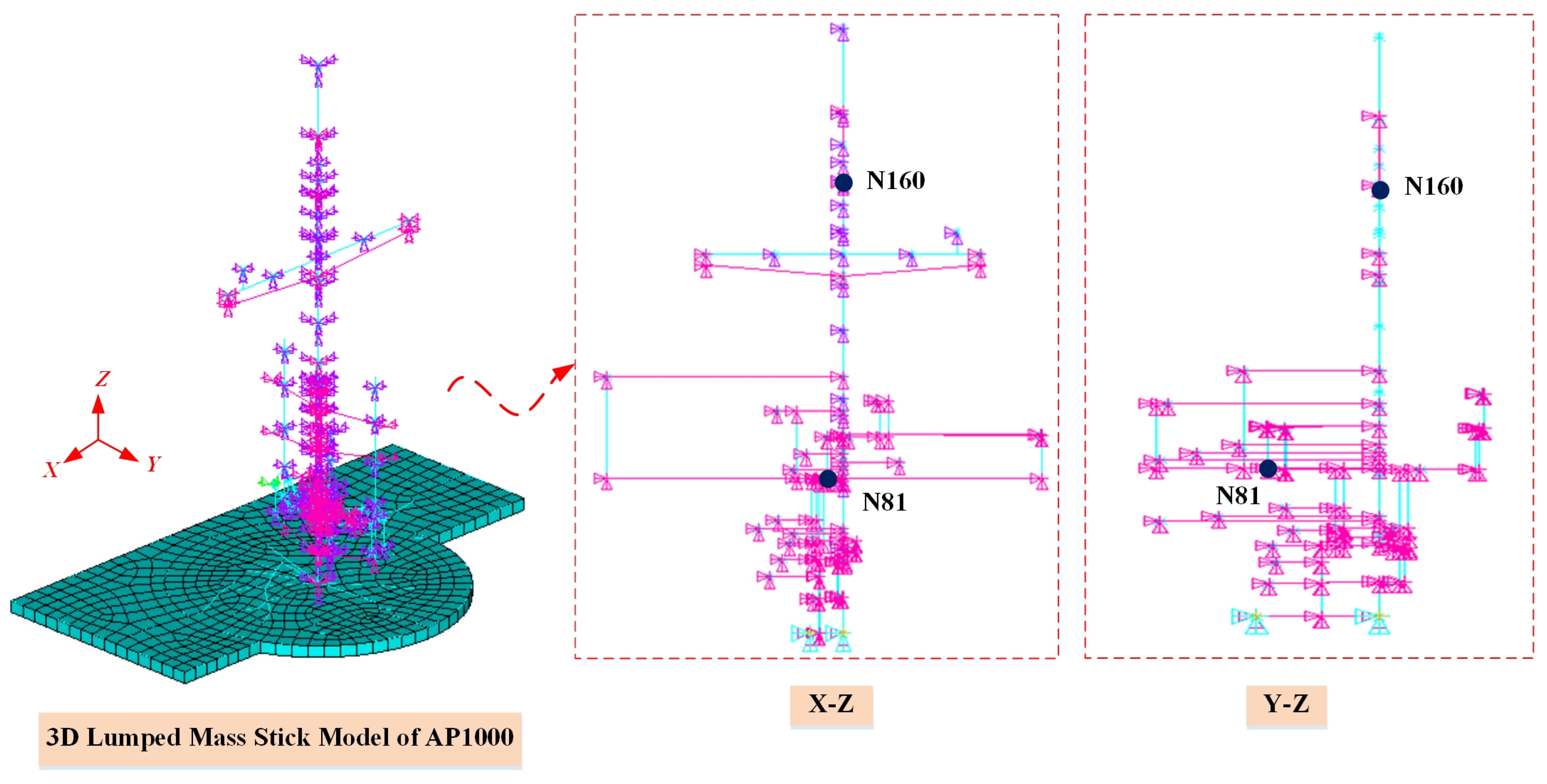
Due to the complexity of the upper structure, this study selected Node 81 at an elevation of 134.9 feet within the shield building and Node 160 at the bottom of the shield building air intake (elevation 265 feet) as key points for calculating floor response spectra. The 5% damping ratio response spectrum results for these two nodes in three directions under various cases are presented in
Figure 14, in which the red line represents the AP1000 standard design soft soil foundation case.
A comparison of floor response spectrum between the OF case and the SD case indicates that at key nodes, the horizontal x-direction spectrum values exceed those of the standard design within the narrow low-frequency band of approximately 0.6–0.9 Hz, while remaining lower in all other frequency bands; for the horizontal y-direction, spectrum values exceedances occur in the bands of approximately 0.7–1.1 Hz and 4.2–5.4 Hz, concentrated in both low and relatively higher frequency ranges; in the vertical direction, spectrum values surpass the standard design across the 3.4–6.0 Hz band, primarily within high frequencies, demonstrating that the foundation of NI structure under original conditions cannot meet seismic adaptability requirements.
The use of pile foundations to treat the original site demonstrates a reduction in low-frequency floor response spectrum values compared to the original foundation. Taking Node 81 as a specific example: For the horizontal x direction, the maximum low-frequency response spectrum value under original site conditions was 0.7 g. After reinforcement with CFG piles and rock-socketed piles, this maximum value decreased to 0.55 g and 0.48 g respectively. Under RS Pile case condition, the low-frequency response spectrum is enveloped by the standard design spectrum. Conversely, due to a corresponding increase in high-frequency spectrum amplitudes, individual frequency points in the high-frequency range exceed the standard design spectrum values to varying degrees. For the horizontal y-direction, while the variation magnitude in acceleration is smaller compared to the x-direction, the overall trend remains consistent. Regarding the vertical direction, the response spectrum trend after rock-socketed pile treatment is largely similar to that of the original foundation, while the CFG pile response spectrum values increase to varying degrees.
Therefore, the comparative analysis of the floor response spectrum across all three directions demonstrates that the rock-socketed piles yield a more significant improvement in foundation treatment compared to CFG piles. Notably, in the high-frequency range, the increased foundation stiffness resulting from piling allows high-frequency components of seismic waves—previously filtered by soft soil layers—to propagate to the surface, leading to elevated spectrum values. However, in the dynamic analysis of NI structures, low-frequency modes predominantly govern structural response. The amplification observed in the high-frequency response spectrum can be effectively mitigated through targeted seismic strengthening measures.
Cost and Construction Analysis
To provide more comprehensive guidance for engineering practice, a cost and construction analysis of different pile types is conducted. The rock-socketed bored pile (φ1.5 m) uses C40 concrete with minimum reinforcement (0.3%), costing approximately ¥2950 per meter (concrete: ¥619.5, rebar: ¥715, construction: ¥1616). Construction requires penetrating rock layers (drilling speed: 0.5–1 m/h), with strict controls on slurry disposal, sediment thickness (≤50 mm), continuous underwater pouring, and rock-socket depth verification. These requirements result in high implementation complexity and environmental risks.
In contrast, the CFG pile (φ0.6 m, plain C40 concrete) costs only ¥206 per meter (concrete: ¥137, construction: ¥69). It employs a long auger for soft soil drilling (speed: 2 m/min) with simultaneous concrete pumping and pipe withdrawal. However, this method necessitates precise control of withdrawal speed, slump (160–200 mm), and cushion compaction. The process achieves over five times the efficiency of rock-socketed piles, eliminates rebar use and slurry pollution, and is suitable for rapid soft-soil treatment.
The fundamental distinctions lie in the load transfer mechanism (rock-socketed pile relies on end bearing, while CFG piles function via composite foundation principles) and cost-effectiveness (CFG pile costs are typically less than one-tenth of rock-socketed piles). Selection should consider geological conditions, load requirements, and project schedules.


