Article

Behavior of Self-Compacting Concrete Cylinders Internally Confined with Various Types of Composite Grids

by
Aboubakeur Boukhelkhal
1,
Benchaa Benabed
1,
Rajab Abousnina
2 and
Vanissorn Vimonsatit
3,*
1
Civil Engineering Research Laboratory, Amar Telidji University, Laghouat 03000, Algeria
2
School of Civil and Mechanical Engineering, Curtin University, Perth, WA 6102, Australia
3
School of Engineering, Faculty of Science and Engineering, Macquarie University, Sydney, NSW 2109, Australia
*
Author to whom correspondence should be addressed.
Buildings 2025, 15(8), 1286; https://doi.org/10.3390/buildings15081286
Submission received: 3 March 2025 / Revised: 1 April 2025 / Accepted: 7 April 2025 / Published: 14 April 2025

Abstract

Composite grids serve as reinforcement in concrete structures, offering alternatives to conventional steel reinforcement. These grids can be fabricated from various materials, including synthetic polymers, metals, and natural fibers. This study explores the use of composite grids as lateral confinement of self-compacting concrete (SCC) cylinders and examines their impact on the failure mode under axial compression. In the experiment, the types of grids and mesh shapes used were plastic grids of diamond mesh (PGD) and regular mesh (PGT), metallic grids of diamond mesh (MGD) and square mesh (MGS), vegetable grids of Alfa fiber mesh, 10 × 10 mm (VGAF-1) and 20 × 20 mm (VGAF-2), and vegetable grids of date palm fibers (VGDF). The binder of SCC mixtures incorporated 10% marble powder as a partial replacement for ordinary Portland cement (OPC). SCC mixtures were tested in the fresh state by measuring the slump flow diameter, V-funnel flow time, L-box blocking ratio, and segregation index. Cylinders with a diameter of 160 mm and a height of 320 mm were made to assess the mechanical properties of hardened SCC mixtures under axial compression. The results indicate that most of the confined cylinders exhibited an increase in ductility compared to unconfined cylinders. Grid types MGD and PGD provided the best performance, with ductility increases of 100.33% and 96.45%, respectively. VGAF-2 cylinders had greater compressive strength than cylinders with other grid types. The findings revealed that the type and mesh shape of the grids affects the failure mode of confined cylinders, but has minimal influence on their modulus of elasticity. This study highlights the potential of lateral grid confinement as a technique for rehabilitating, strengthening, and reinforcing weaker structural concrete elements, thereby improving their mechanical properties and extending the service life of building structures.

1. Introduction

Concrete is the most widely used material for constructing infrastructure assets. The functionality and durability of structures are critical structural design requirements. On the other hand, infrastructure projects are highly visible to the public, and their appearance impacts community satisfaction. Aesthetically pleasing structures can boost the character of the area, creating a unique identity for a city or region [1]. Designing concrete structures to satisfy architectural requirements can be a challenge, especially when dealing with large-scale projects. Furthermore, reinforced concrete structures suffer from material degradations, generally due to cracking, increased load intensities, corrosion in reinforcing bars, and accidental events such as earthquakes, fire, and blasts [2]. Therefore, providing suitable solutions that enhance the service life of structures is the main area of research. Thus, strengthening structural elements by making them more rigid, stable, and better able to resist any sudden failure is one of the main areas of research. Using composite materials offers many advantages, such as lightness, mechanical and chemical resistance, reduced maintenance, and design flexibility for aesthetic appeal [3]. For several decades, engineers and experts have proposed various techniques and processes for strengthening and reinforcing damaged concrete to enhance its performance and extend the lifespan of building structures [4,5,6,7,8,9].
Applying lateral confinement to concrete columns is a solution to prevent sudden failure, especially during earthquakes. The main controlled parameters of confined concrete are compressive strength (bearing capacity) and ultimate strain (ductility). Concrete-filled steel tube is the most popular confinement technique; however, it has many disadvantages such as weight, cost, and corrosion. The lateral confinement of concrete columns by bonding a composite material to the concrete surface can enhance mechanical properties such as compressive strength and ultimate strain [10]. Furthermore, using composite materials may reduce the risk of crack formation and propagation in concrete. Consequently, lateral deformation decreases due to the mobilization of the lateral confining pressure exerted by the composite [11]. Chin et al. [12] reported that lateral confinement applies pressure to the concrete, which depends on the material and shape of the confinement, and on concrete spalling. External reinforcement using fiber-reinforced polymer (FRP) is a promising technique for reducing the seismic vulnerability of existing structures [13]. In a previous work, Xavier and Mukilan [14] stated that using geogrids of geosynthetic materials as reinforcement to replace conventional transverse steel reinforcement in concrete structures resulted in better ductility, cost reduction, and seismic resilience.
Polymers can be easily formed into circular shapes without sharp bends, thereby effectively mobilizing their tensile capacity [15,16]. Polymer grids are easy to integrate into concrete before casting, and their corrosion resistance allows for a reduced concrete cover thickness. When used as confining reinforcement, polymer grids enhance the ductility of concrete, and an optimal number of polymer grids can improve the overall strength [17,18,19]. In reinforced concrete (RC) columns, polymer grid confinement serves as secondary confinement reinforcement, enhancing the strength and ductility of the columns and reducing concrete spalling [16,20,21,22]. The tensile rupture of the polymer grids used as confinement in concrete dominates the failure mode of confined concrete, leading to a higher deformation capacity compared to unconfined concrete.
Dai et al. [23] examined the effectiveness of polyethylene naphthalate (PEN) and polyethylene terephthalate (PET) as lateral confinement materials for concrete. Their findings indicated that while PET and PEN significantly enhance the ductility of concrete, they only marginally improve its compressive strength. Similarly, Peled [24] explored the use of textile fabrics (PEN and PET) for confining concrete columns and found that they can effectively enhance the columns’ deformation capacity. Additionally, Rousakis [25,26] reported that incorporating polypropylene fiber ropes and low-modulus vinylon as confinement materials for concrete cylinders can improve both ductility and strength.
Another type of lateral confinement in concrete is ferrocement laminate confinement, which is formed by a combination of cement mortar reinforced with a thin layer of wire mesh. The mesh can be metallic or made of other materials, such as fibers, glass fibers, and woven vegetable fabric. Several advantages of this technique have been reported, such as enhanced strength, crack resistance, ductility, and durability. Paramasivam et al. [27] used a ferrocement laminate jacket to reinforce concrete flanged beams. Their experiment revealed that ferrocement laminate jacketing is highly effective in reinforcing concrete flanged beams. It improves the cracking strength and stiffness of beams. However, compatibility between the concrete surface and the ferrocement laminate is critical, since it has a considerable impact on their effectiveness.
Nassif et al. [28] evaluated the efficacy of adding a thin layer of ferrocement to improve the ductility and cracking strength of concrete beams. It was also discovered that increasing the number of layers improves the cracking stiffness of both composite beams. The difference between using a square mesh and a hexagonal mesh as reinforcement was investigated. It was found that specimens with a square mesh outperformed those with a hexagonal mesh. Takiguchi and Abdullah [29] studied columns strengthened with varying quantities of wire mesh layers. All the specimens were subjected to cyclic lateral stresses combined with a constant axial load. It was reported that the shear strength of columns with jacketing increased. Kumar et al. [30] investigated bridge pier specimens strengthened with ferrocement jackets, which demonstrated increased stiffness, ductility, and strength. Bansal et al. [31] examined the effect of the wire mesh orientation of ferrocement jackets in retrofitting concrete beams. The results revealed that with an orientation at 45°, the energy absorption was the maximum, demonstrating the importance of the effects of wire mesh orientation [32].
According to the existing literature, lateral grid confinement positively influences the mechanical behavior of concrete [2,3,11,33,34]; however, when used as confinement in SCC, its impact remains fundamentally unexplored. This study investigates three key parameters of grid confinement—grid type, mesh shape, and material characteristics—to evaluate their effects on the load-carrying capacity and ultimate strain of SCC cylinders subjected to axial compression. The experiment utilized plastic, metallic, and vegetable grids, each featuring different mesh shapes, including diamond, square, rectangular, and triangular configurations.

2. Materials and Methods
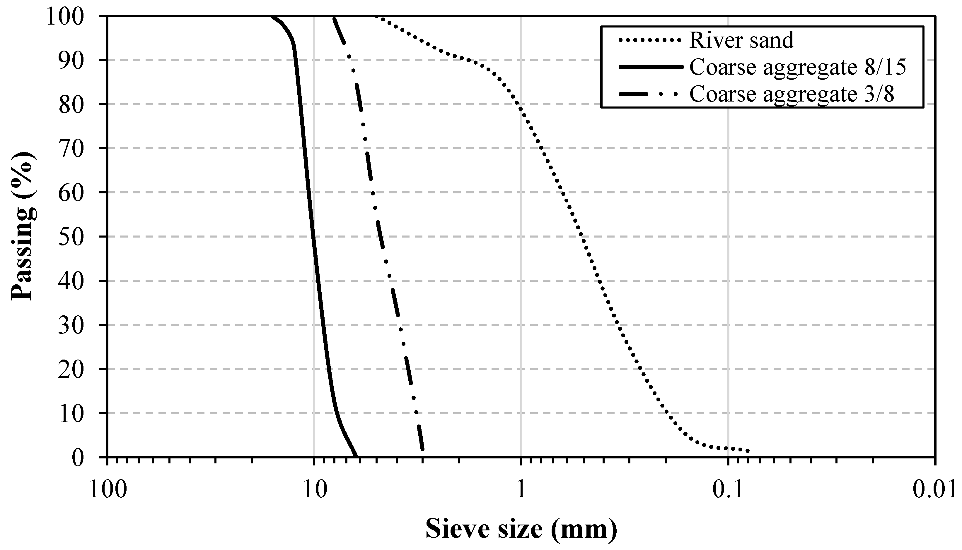
2.1. Materials

Ordinary Portland cement of CEMI 42.5 type was used in all SCC mixtures; this cement was manufactured by Algerian cement company (M’sila, Algeria). Marble powder (MP) resulting from the cutting, shaping, and lustrating of marble stones was used as a partial cement replacement. The chemical composition and physical properties of the cement and marble powder are given in Table 1.
Two types of aggregates were used in this study: river siliceous sand (0/5) and crushed gravel (3/8 and 8/15) of calcareous origin. The physical properties of different aggregates are presented in Table 2. The particle size distributions of fine and coarse aggregates are plotted in Figure 1.
Three types of the grid (plastic, metal, and vegetable, made from Alfa fibers and date palm fibers) with different sizes and mesh shapes (square, rectangle, triangle, and diamond) were used as confinement materials in this investigation; the only exception was the palm grid, which was incorporated as it was received. The properties of grids, including their physical and mechanical properties, were tested. Figure 2 shows the tensile test on the different grids used. The properties are presented in Table 3.

2.2. Mix Proportions of SCC

One composition of SCC was tested with various types of grids (plastic, metallic, and vegetable) and mesh shapes (diamond, square, rectangular, and triangle). In this composition, cement was partially replaced by 10% marble powder in order to produce an eco-efficient SCC [35,36]. To obtain the desired fluidity, a polycarboxylate superplasticizer-based high-range water reducer (HRWR) was used as a chemical admixture. Table 4 presents the mix proportions of SCC, the results of its fresh properties, and its classification according to EFNARC [37].

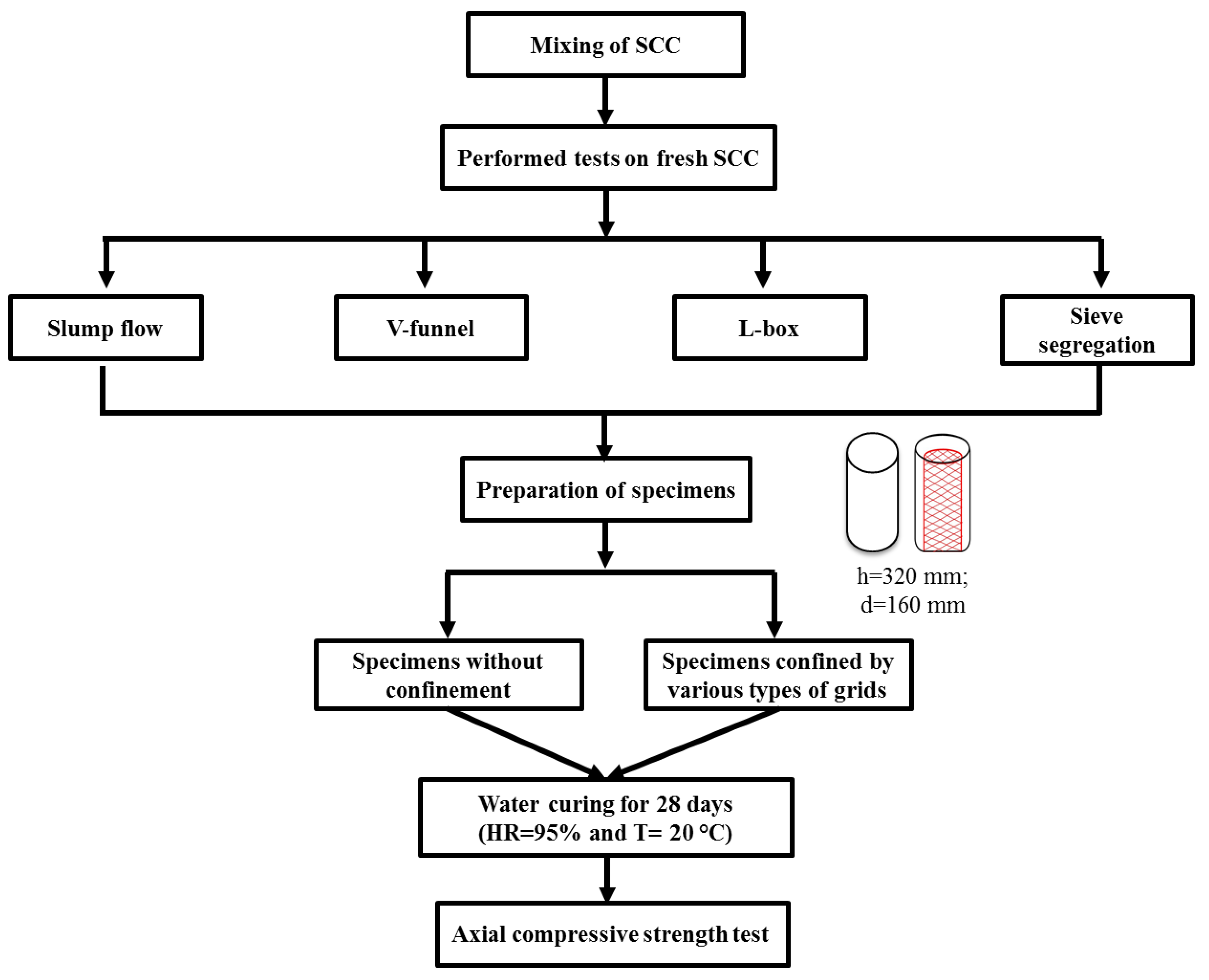
2.3. Experimental Program

All SCC mixtures were tested in both fresh and hardened states. The laboratory-based experimental program is illustrated in Figure 3.

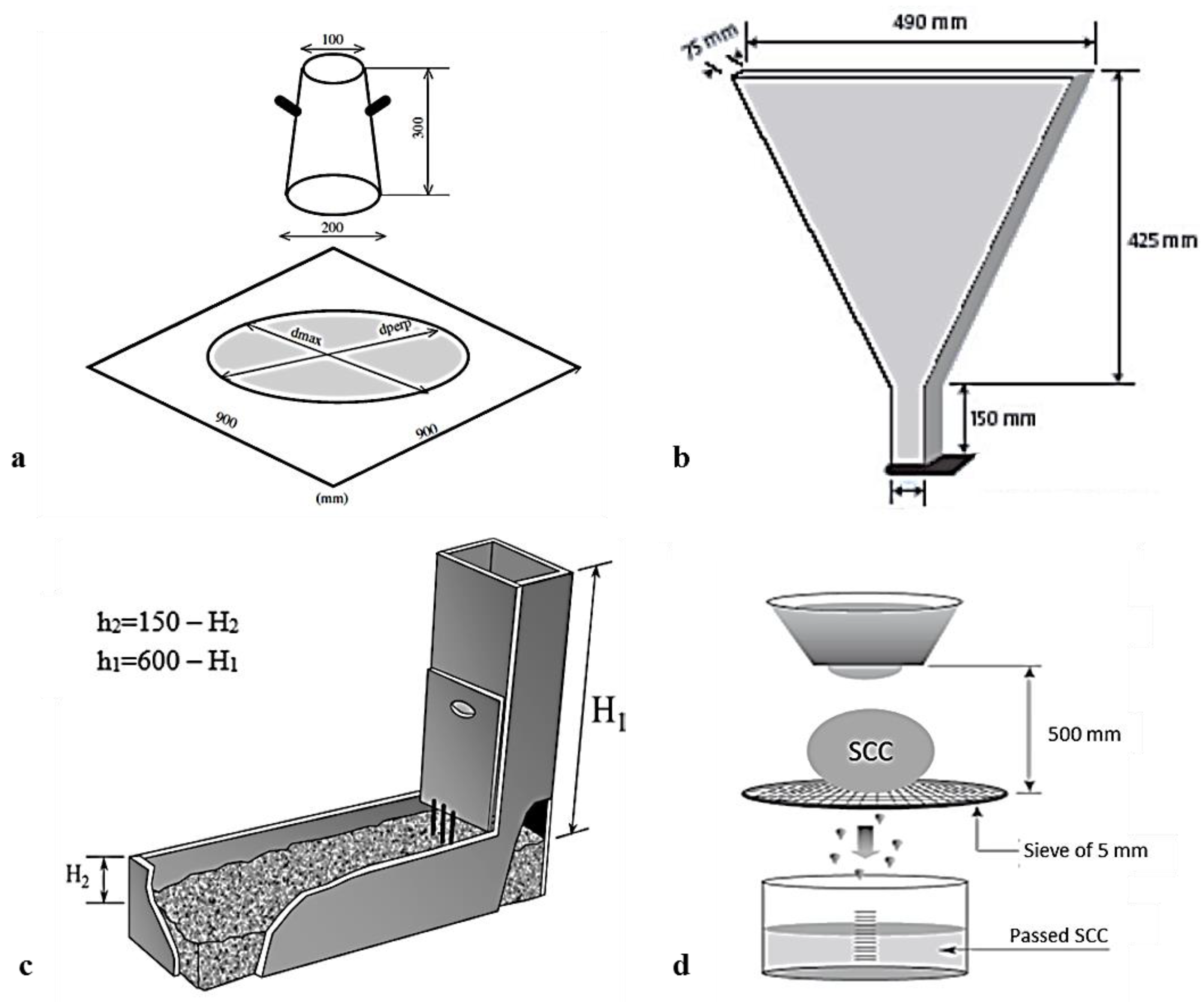
2.3.1. Tests on Fresh SCC

According to EFNARC requirements, slump flow, V-funnel, L-box, and sieve segregation tests can be used to characterize the filling and passing abilities and the resistance to segregation of fresh SCC [37]. Figure 4 shows the fresh tests conducted on SCC mixtures.

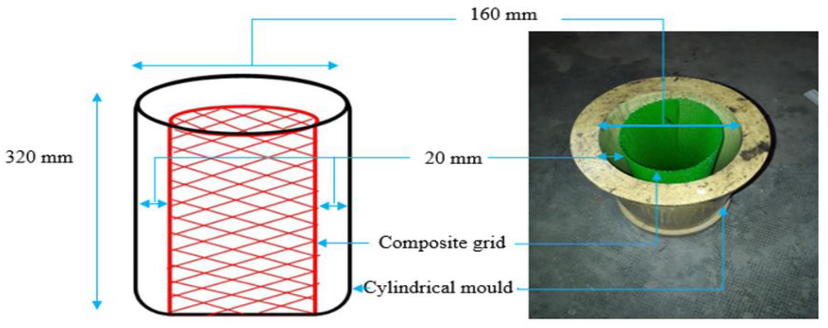
2.3.2. Method of Confinement
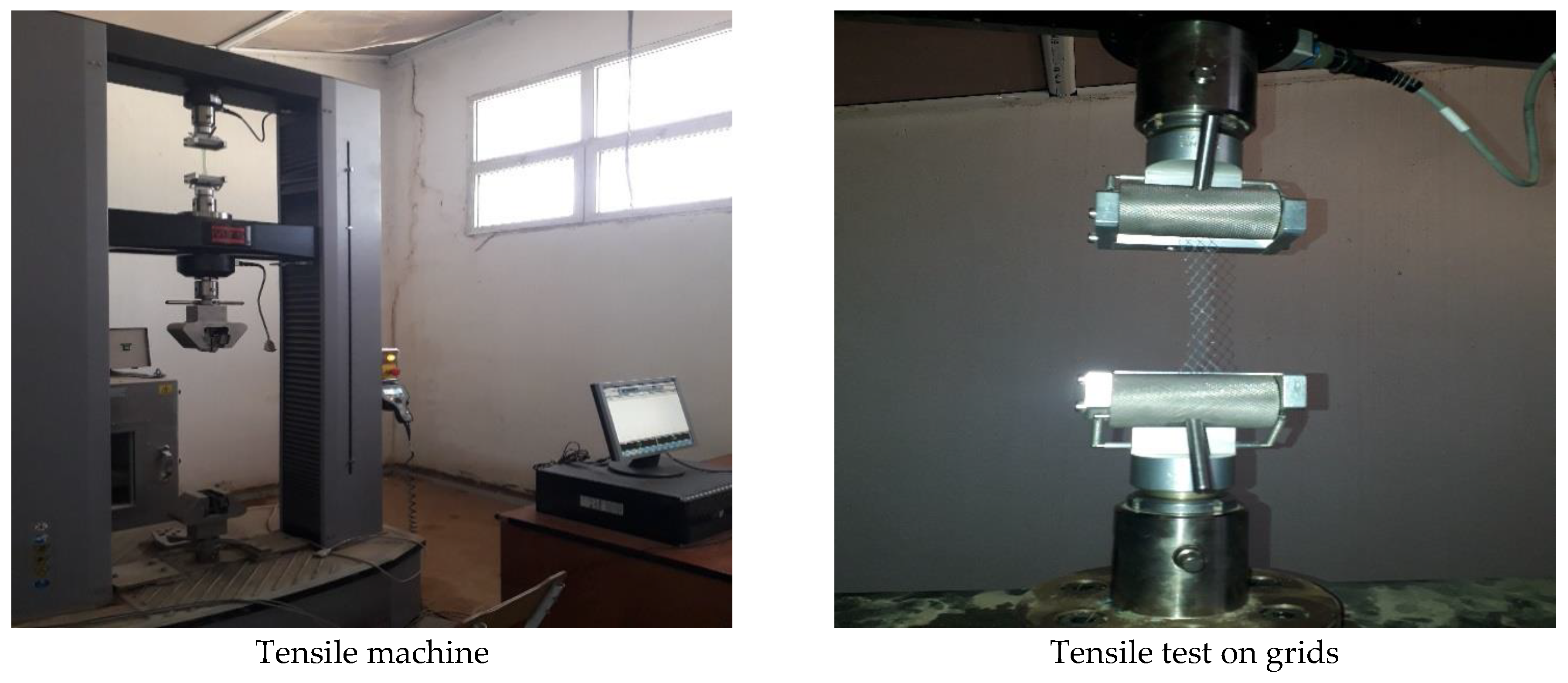
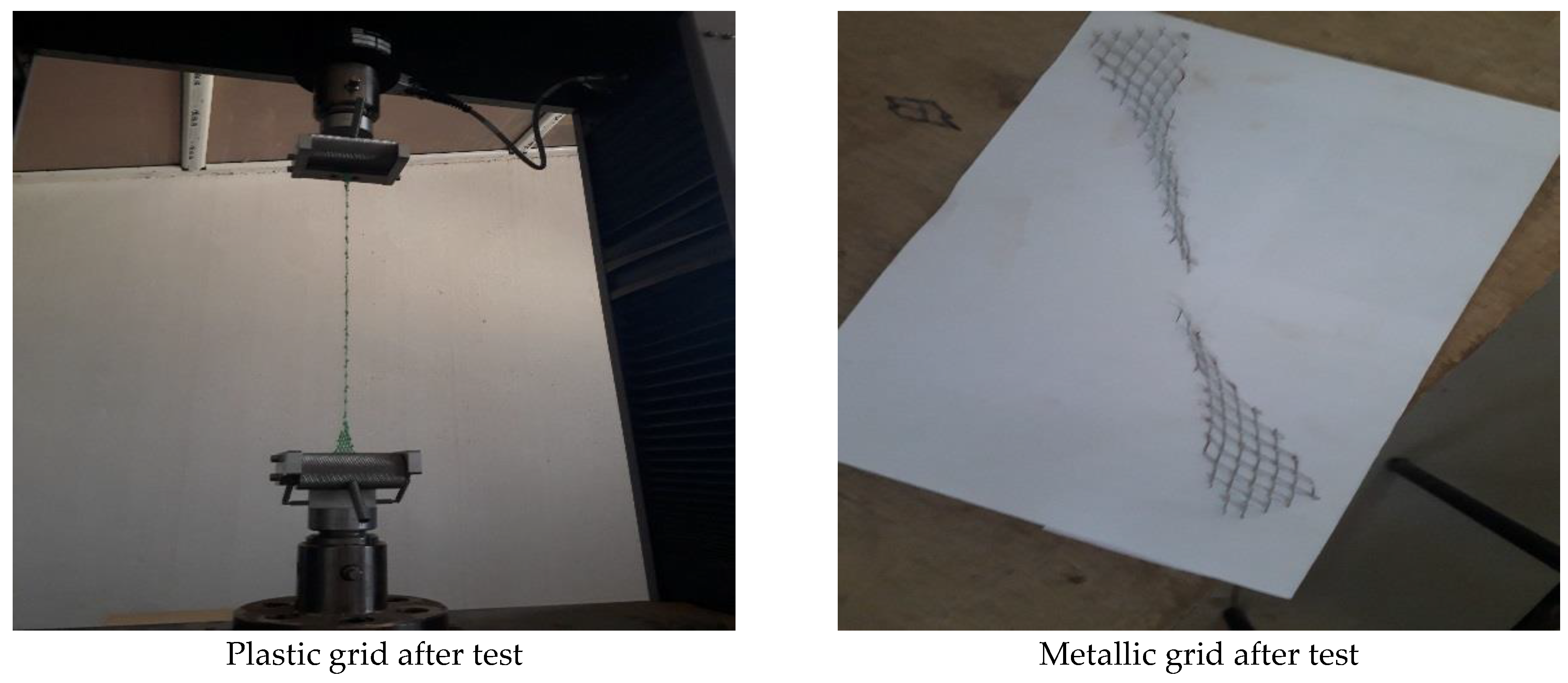
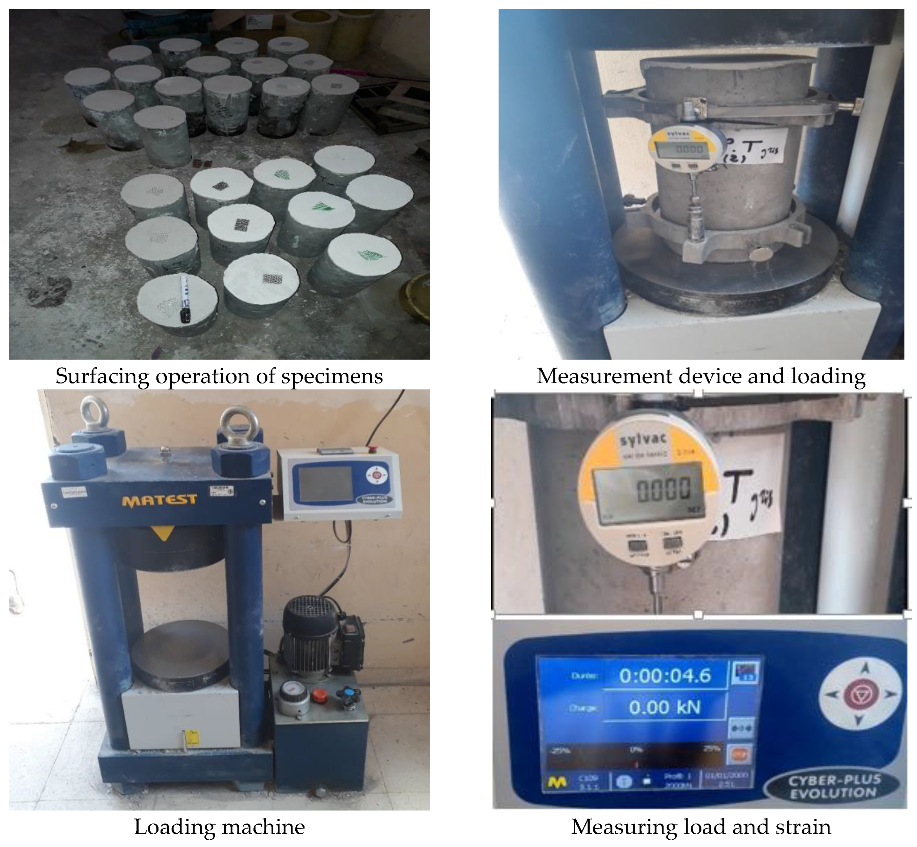
The technique proposed in this work consists of circumferentially integrating plastic, metal, and vegetable grids into the concrete matrix. Three cylinders, each 160 mm in diameter and 320 mm high, were tested for each mixture. The different composite grids were placed inside a cylindrical mold with a 20 mm thick coating, as shown in Figure 5.

2.3.3. Test Setup

The specimens are subjected to uniaxial compression until failure using a MATEST-type hydraulic machine with a capacity of 2000 kN. A quasi-static loading rate of 0.5 kN/s is applied [38]. Displacement control is provided by a digital comparator with an accuracy of 0.001 mm, which allows for the determination of strain, and the machine screen indicates the force values in kN. The comparator values and the screen are read at the same time to plot the stress–strain curves. To ensure good readings, two video cameras were used throughout the test. Figure 6 shows the measurement devices and loading test of the specimens.

3. Results and Discussion

3.1. SCC Fresh Properties

Using the equipment presented in Figure 4 with the test results provided in Table 4, a slump flow value of 760 mm was obtained, indicating good filling ability of SCC. The V-funnel test had a flow time of 9 s and belonged to the VS2/VF2 class. It can be concluded that the SCC mixture has a highly acceptable filling capacity, which is suitable for all types of structures.
The L-box test revealed that the SCC flow occurred without blocking. The ratio of the concrete height in the horizontal and vertical sections (h2/h1 ratio) was more than 80%, resulting in a high flow capacity.
The segregation resistance of SCC, as determined by the sieve stability test, demonstrated that the SCC mixture was homogeneous and stable, with no risk of segregation. Visual inspection during all tests showed that there was no problem of segregation or bleeding of the fresh SCC.

3.2. Axial Load–Strain Behavior

Figure 7 shows the stress–strain curve of unconfined SCC under axial compression; the curve has an initial slope up to an inflection point, followed by a plastic deformation zone. The stress increased to a maximum ultimate strength of 42.25 MPa and then decreased until it reached the post-peak value of 20 MPa at failure. The deformation continued to increase as the applied load increased up to an ultimate value of 6%.
The evolution of stress as a function of the strain of SCC confined by plastic grids with different mesh shapes and sizes is shown in Figure 8. To better estimate the efficiency of the type of grid, a comparison with unconfined SCC was realized. The results show that the stress–strain curves of the control SCC and those of confined SCC were similar. The ascending part represents the elastic phase of the material. The ultimate strength of the unconfined SCC was greater (42.25 MPa) than that of the confined SCC. The descending part of the curve represents the plastic phase of the composite material, which varies from one type of grid to another. From the point of view of ultimate strain, the SCC mixtures confined by plastic grids with a diamond mesh shape (PGD) had better ductility, with a strain value of 11.63%, which is 96.45% more than that of the corresponding control mix. SCC confined by PGT developed an ultimate strain similar to unconfined SCC.
A comparison between the stress–strain curves of cylinders confined by metal grids and the reference cylinders is shown in Figure 9. The results indicate that mixtures confined by metal grids with a diamond shape (MGD) offered the best mechanical behavior with a strength (41.86 MPa) similar to that of unconfined SCC (42.25 MPa); however, the strength of SCC confined by square metal grids (MGS) was 33% less than that of the corresponding control SCC. The ultimate strain of the confined cylinders was higher compared to that of the reference SCC. SCC concrete confined by both MGS and MGD reached similar ultimate strains of 11 and 12%, respectively. This means that the confined SCC had a larger plastic zone compared to the unconfined SCC.
Figure 10 shows the curves of the mechanical behavior of SCC confined by vegetable grids. The vegetable grids based on Alfa fibers (VGAF-2) provided a better bearing capacity than the unconfined SCC and the SCC confined by other types of vegetable grids (VGAF-1 and VGPF). With regard to ductility, the maximum ultimate strain value of 11‰ was recorded for VGAF-2, indicating the good ductility of this composite mixture. Ait Tahar and Bahar [34] examined the influence of the size of composite mesh grids on the mechanical strength and ductility of confined concretes and found that concrete confined by grids with a small mesh size has better ultimate strength and ductility than that confined by grids with a large mesh. These results are in contradiction with our results, especially for alfa fiber grids, where decreasing the mesh size from 20 to 10 mm reduced both strength and ductility.

3.3. Evaluation of Mechanical Properties

Figure 11, Figure 12 and Figure 13 represent the variations in the strength, ultimate strain, and elasticity modulus of all the SCC mixtures studied, respectively. Figure 11 shows that the strength of SCC confined by MGD, PGD, and VGAF-2 was similar to that of unconfined SCC. The strength of the other mixtures was less than that of the control SCC; their strength class was 30 to 35 MPa. SCC confined by MGS, PGT, and PGR developed the lowest strength. Noting that the dotted line was used to compare the values of the control and other mixtures.
Figure 12 indicates that the ultimate strain of all confined SCC cylinders was higher than that of the corresponding reference SCC, except for SCC cylinders confined by PGT, which developed the lowest ultimate strain. This could be attributed to the smaller size of the PGT mesh, which may affect the adhesion between concrete and grid. These results showed the importance of using composite grids for improving the ductility of SCC. Concrete with high ductility is strongly recommended in the seismic design of structures because it increases energy absorption during an earthquake and prevents the sudden destruction of structural elements [8].
Figure 13 depicts the variation in the elasticity modulus of all SCC mixtures. The analyses of the results revealed that the elasticity modulus is higher for all SCC confined mixtures compared to the unconfined SCC, except for SCC made with Alfa fibers with a large mesh (VGAF-2). The SCC mixture confined by PGD developed the highest elasticity modulus, 13.74 GPa, which is 34% more than that of the unconfined SCC. Concrete samples confined by plastic grids and metal grids with a diamond mesh shape and vegetable grids with Alfa fibers (VGAF-2) exhibited the best performance. The PGD and MGD grids with a diamond mesh shape enabled a better distribution of tension on the four sides of the mesh compared to those with rectangular and triangular mesh shapes.
The results obtained showed the advantageous role of grids in improving the performance of confined SCC, especially in terms of ductility, except for confinement by plastic grids with a triangular mesh, which decreased both mechanical and ductility properties. This type of grid is characterized by its larger mesh, possibly because it was thicker than the other grids, and the thickness affected the concrete–grid interfacial zone and caused poor adhesion. Ghernouti [2] studied the mechanical behavior of ordinary concrete confined by metal and polypropylene grids with hexagonal and diamond grid shapes. They found that the diamond mesh shape increased the strength and ductility of concrete. Confinement by VGAF with a square mesh (20 × 20 mm) enhanced the passing ability of fresh SCC through the mesh grid and resulted in a more homogeneous mixture with improved SCC-grid adhesion, consequently leading to higher strength and ductility.

3.4. Discussion

3.4.1. Strength Gain and Ductility Gain

In order to better show the effect of using different confinement grids, the results are presented in the form of strength gain (SG) and ductility gain (DG) using Equations (1) and (2). Table 5 summarizes the results obtained.
SG = (fcc − fco)/fco × 100
DG = (εcu − εu)/εu × 100
fcc: Compressive strength of confined concrete
fco: Compressive strength of unconfined concrete
εu: Ultimate axial strain of unconfined concrete
εcu: Ultimate axial strain of confined concrete
From Table 5, it is noted that the best performances obtained are those of SCC confined by plastic and metal grids with a diamond-shaped mesh, as well as by vegetable grids VGAF-2. This improvement in terms of resistance and ductility of the SCC can be attributed to the very high mechanical properties of the diamond-shaped mesh grids compared to the other grids. For SCC confined by VGAF-2, this improvement in mechanical performance is attributed to the size of the grid meshes, which allows good adhesion between the concrete and the grid, resulting in less pressure applied by the aggregates on the grids.

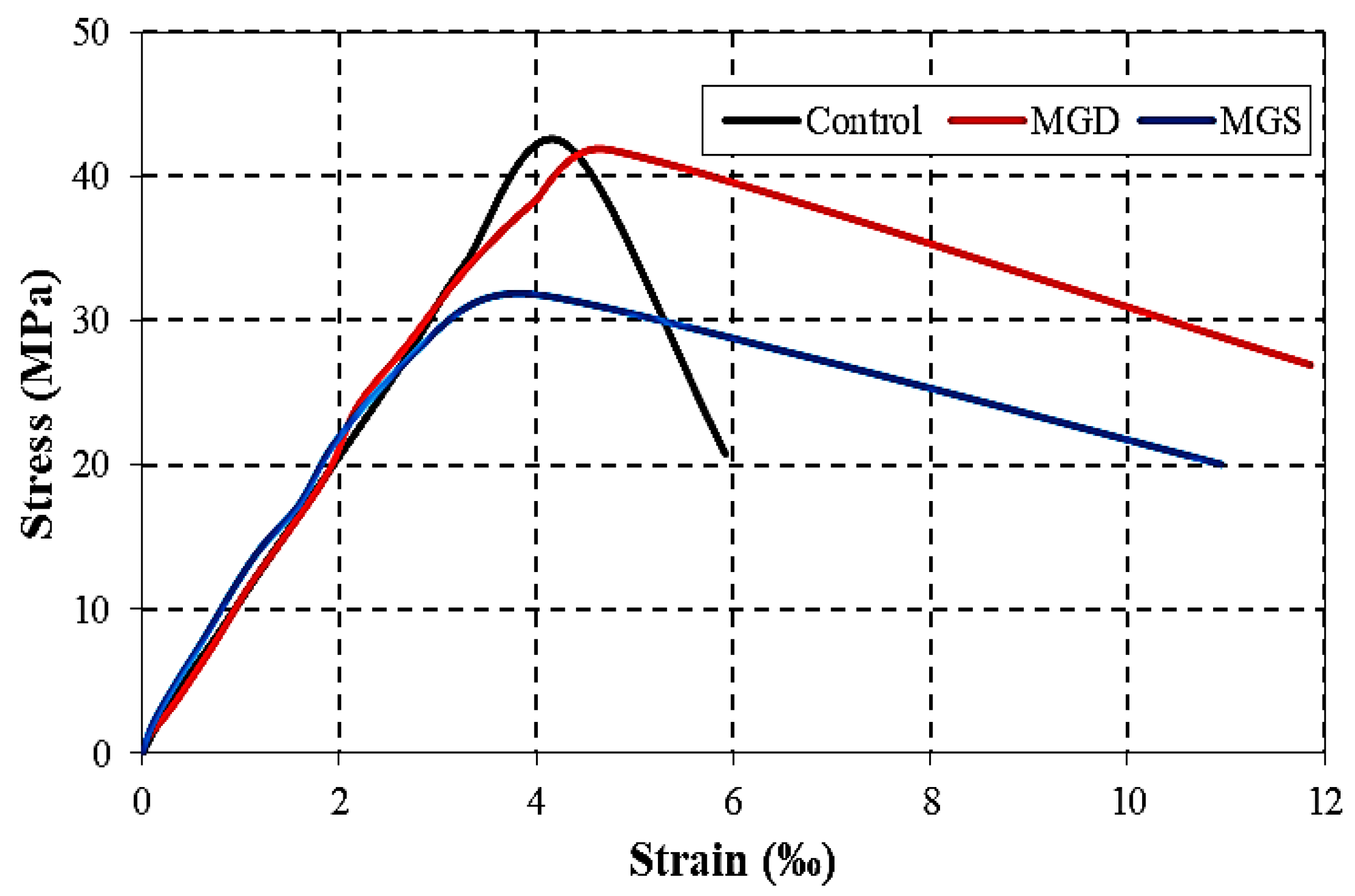
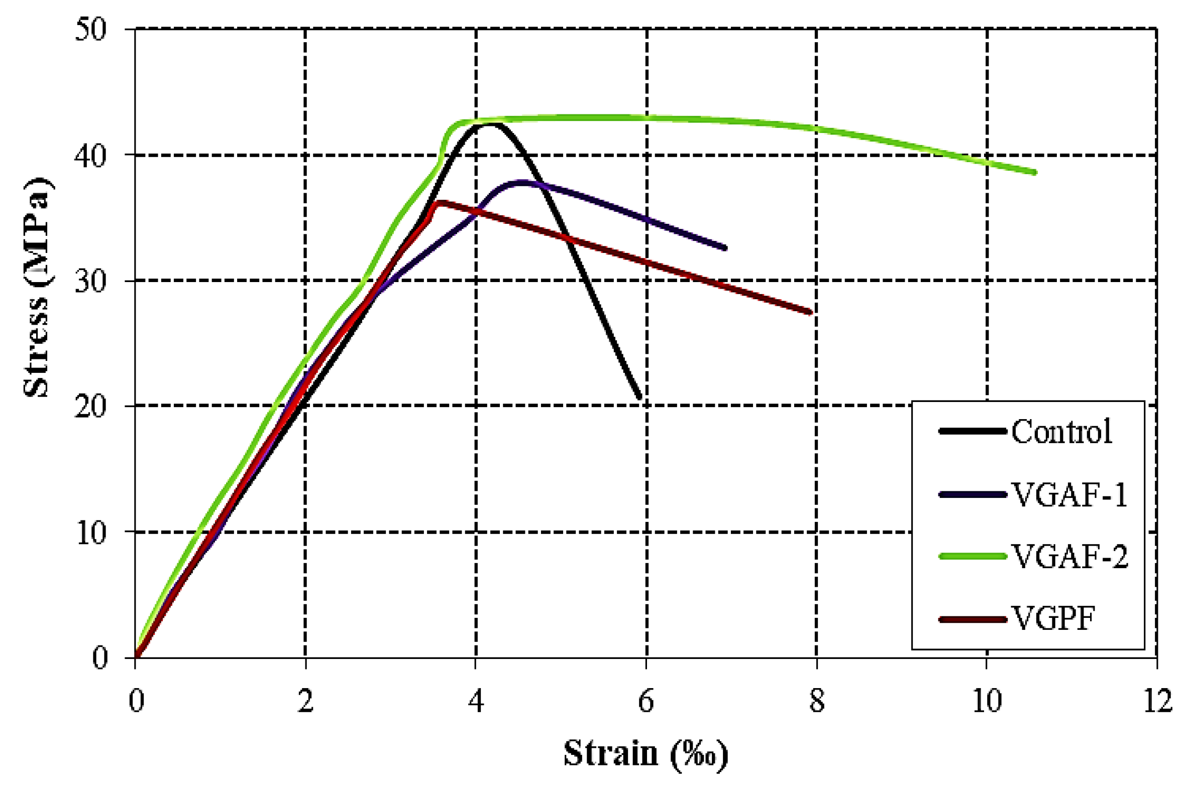
3.4.2. Axial Stress as a Function of Axial Strain

Typically, all the curves obtained for confined concrete have an initial slope that follows that of unconfined concrete up to an inflection point, followed by a zone of large plastic deformation arriving at the collapse of the material. Depending on the efficiency of confinement and stress level, the plastic zone varies considerably from one confinement variant to another.

3.4.3. Mechanical Behavior of Unconfined and Confined SCC Samples

Based on the results, it was noted that all the cylinders confined with different composite grids exhibited behavior that can be divided into three phases [39,40]:
  • A first practical linear phase before micro-cracking of the concrete remains similar to unconfined SCC up to about 50% of the breaking load, so the modulus of elasticity is not very sensitive to the presence of the composite.
  • A second curved phase of the ascending part, during which the concrete micro-cracks and the grid fibers are put in tension.
  • A third descending phase, during which the force is absorbed by the fibers of the composite grids, which hold the cracked concrete until failure.
In this work, the confinement of concrete cylinders is obtained by the circumferential integration in the concrete matrix of plastic grids, metal grids, and vegetable grids. The different grids offer various elasticity moduli and rigidities that can modify the mechanical behavior of confined concrete under an axial compressive load, thus improving its ductility and, in some cases, its resistance.
Concrete samples confined by plastic grids showed a decrease in resistance compared to unconfined concrete. This is probably due to the stiffness of the grids, which concentrate the entire compressive load on the confining layer, causing rupture of the specimen at that layer. A clear improvement in ductility of 96.45% and 32.77% was observed for concretes confined by PGD and PGR, respectively. This improvement in ductility is due to the significant elongation (strain at break) of grids, which allows for more deformation of confined concrete. For concrete confined by PGT, a loss in ductility is recorded due to its high thickness, which separates the concrete section of the coating from the core concrete of the tested specimen, resulting in poor adhesion.
Concrete samples confined by MGD and MGR recorded a remarkable improvement in ductility, of the order of 100.33% and 85.13%; this is due to the compression confinement effect of the grids, which prevents the initiation and subsequent propagation of cracks in the concrete. In terms of resistance, it is noted that concrete samples confined by MGD grids exhibit values similar to those of unconfined concrete. In contrast, a low resistance of columns confined by MGS was recorded compared to the reference concrete.
The confinement of concrete by vegetable grids improves ductility. A gain in ductility of the order of 16.89%, 78.37%, and 33.78% was obtained for VGAF-1, VGAF-2, and VGPF, respectively. Confining by VGAF-2 slightly increases the strength of concrete compared to confinement by VGAF-1 and VGPF.
In general, the different results obtained clearly show that the ductility of confined cylinders increases compared to unconfined cylinders. This positively influences the mechanical performance of concrete.

3.4.4. Influence of the Shape of the Grid Mesh on the Behavior of Confined SCC Samples
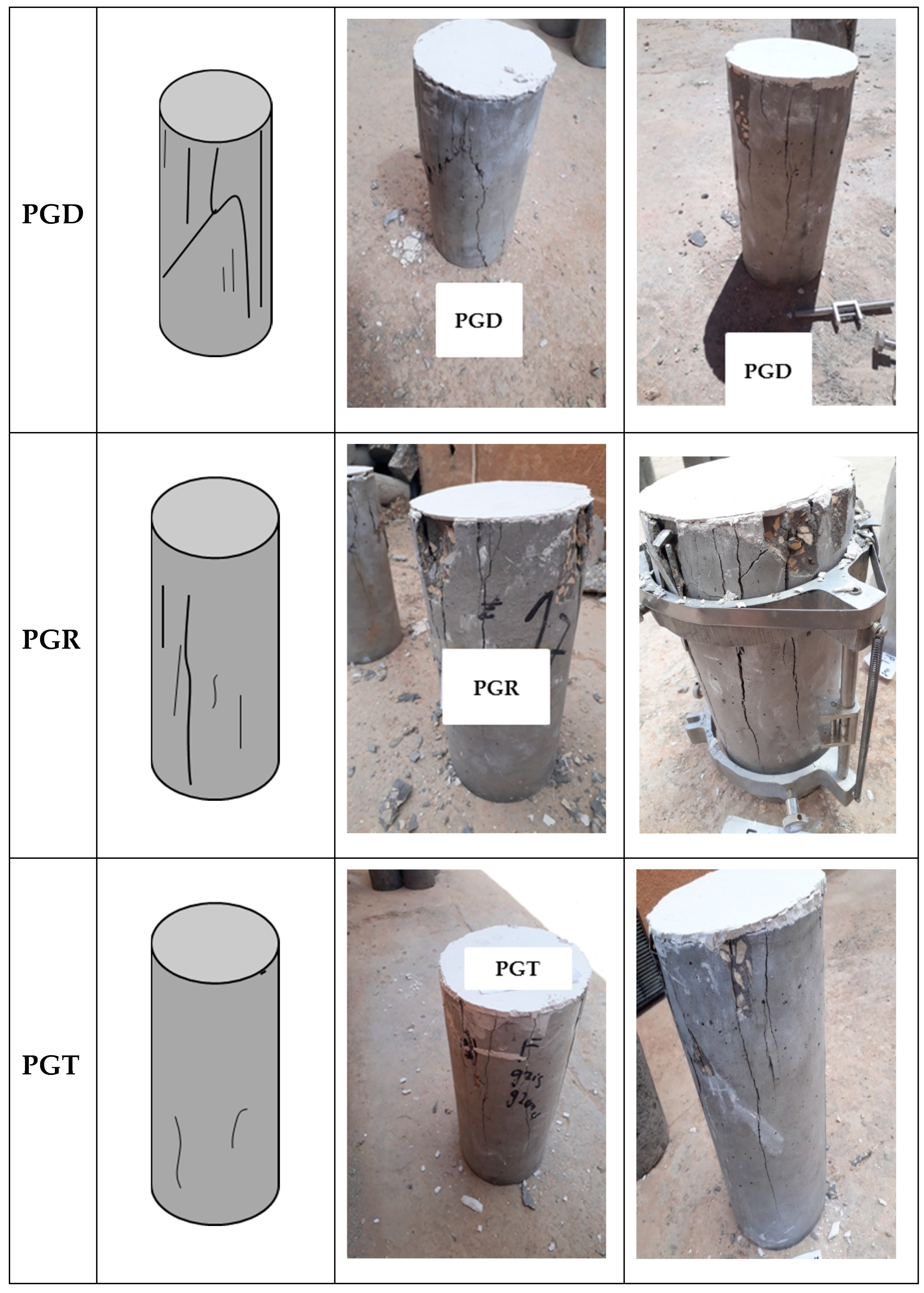
From the results obtained, it can be concluded that all types of grids used for confinement improved the mechanical behavior of concrete, with the exception of confinement by PGT of a triangular mesh, for which a decrease in mechanical properties was noted. Note that the thickness of this grid (PGT) is greater compared to other types of grids, which possibly influences the concrete–grid interface area and leads to poor adhesion. The best mechanical performances are obtained for columns confined by PGD, MGD, and VGAF-2. PGD and MGD have diamond-shaped meshes; this shape allows for a better distribution of tension forces on the four sides of the mesh. Ghernouti [2] studied the mechanical behavior of ordinary concrete confined by metal grids and polypropylene grids with hexagonal and diamond-shaped meshes. He found that grids with diamond-shaped meshes improve the compressive strength and ductility of composites. VGAF-2 grids have a square-shaped mesh measuring 20 × 20 mm, which facilitates the circulation of fresh concrete and results in more homogeneous concrete, both at the level of the coating layer and the core of the concrete.

3.5. Failure Modes

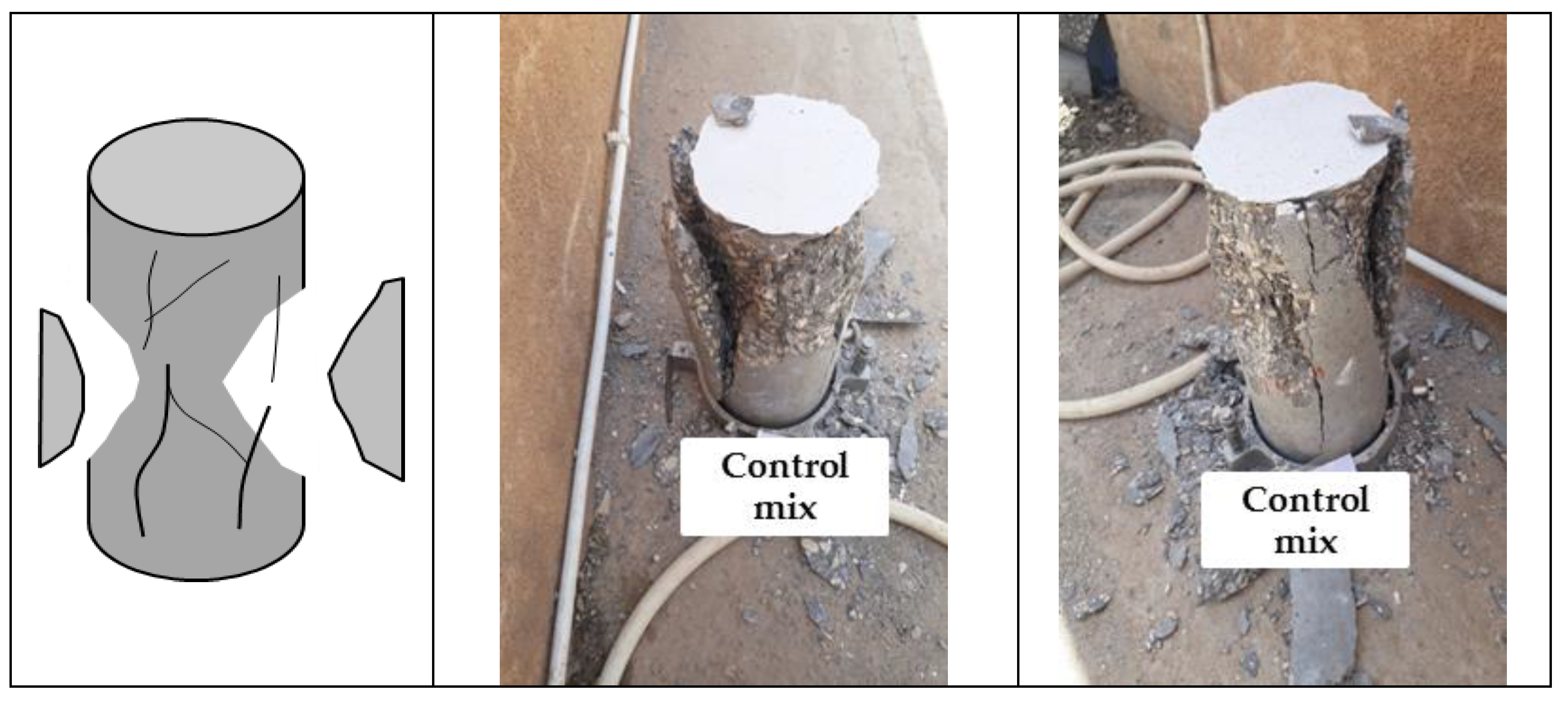
3.5.1. Unconfined Concrete

Figure 14 shows the failure mode of an unconfined concrete cylinder. As can be seen in this figure, a large number of vertical cracks were generated along the direction of the load application, followed by splitting of concrete at the mid-height section on all sides of the specimens. When a concrete cylinder is subjected to a uniaxial compressive load, the concrete is subject to tension in a direction perpendicular to the loading. If there is no confinement effect at both ends of the cylinder, splitting failure of the specimens is expected due to tension in the direction perpendicular to the loading [41].

3.5.2. Confined Concrete with Plastic Grids

Figure 15 illustrates the failure characteristics of confined specimens with three different shapes of plastic. In specimens confined by a diamond grid shape, the cracks were mostly vertical, with only one inclined crack. Specimens confined by a rectangular grid shape showed a large number of vertical cracks, while the number of cracks on the surface of the specimens confined by a triangular grid shape gradually decreased. The low number of cracks in the PGR and PGT cylinders could be attributed to the high number of meshes, which prevents the formation of cracks and their propagation.

3.5.3. Confined Concrete with Metallic Grids

The failure modes of SCC cylinders confined by various shapes of metallic grids are shown in Figure 16. The failure patterns indicate that as the axial compressive load increased, many vertical cracks appeared in the mid portion of the specimen, and some of those continued until the end. It can be noted that cracks are more severe in the case of a square grid shape compared to a diamond grid shape. This behavior may be due to the difference in characteristics between the square mesh shape and the diamond mesh shape. Square grids have less thickness (0.5 mm) than diamond grids (1 mm). In addition, the diamond-shaped grids had a larger mesh size (5 × 5 mm), which facilitated the penetration of mortar through the spacing of the metal fibers, thereby enhancing the bond between the grids and the matrix and limiting crack development [42].

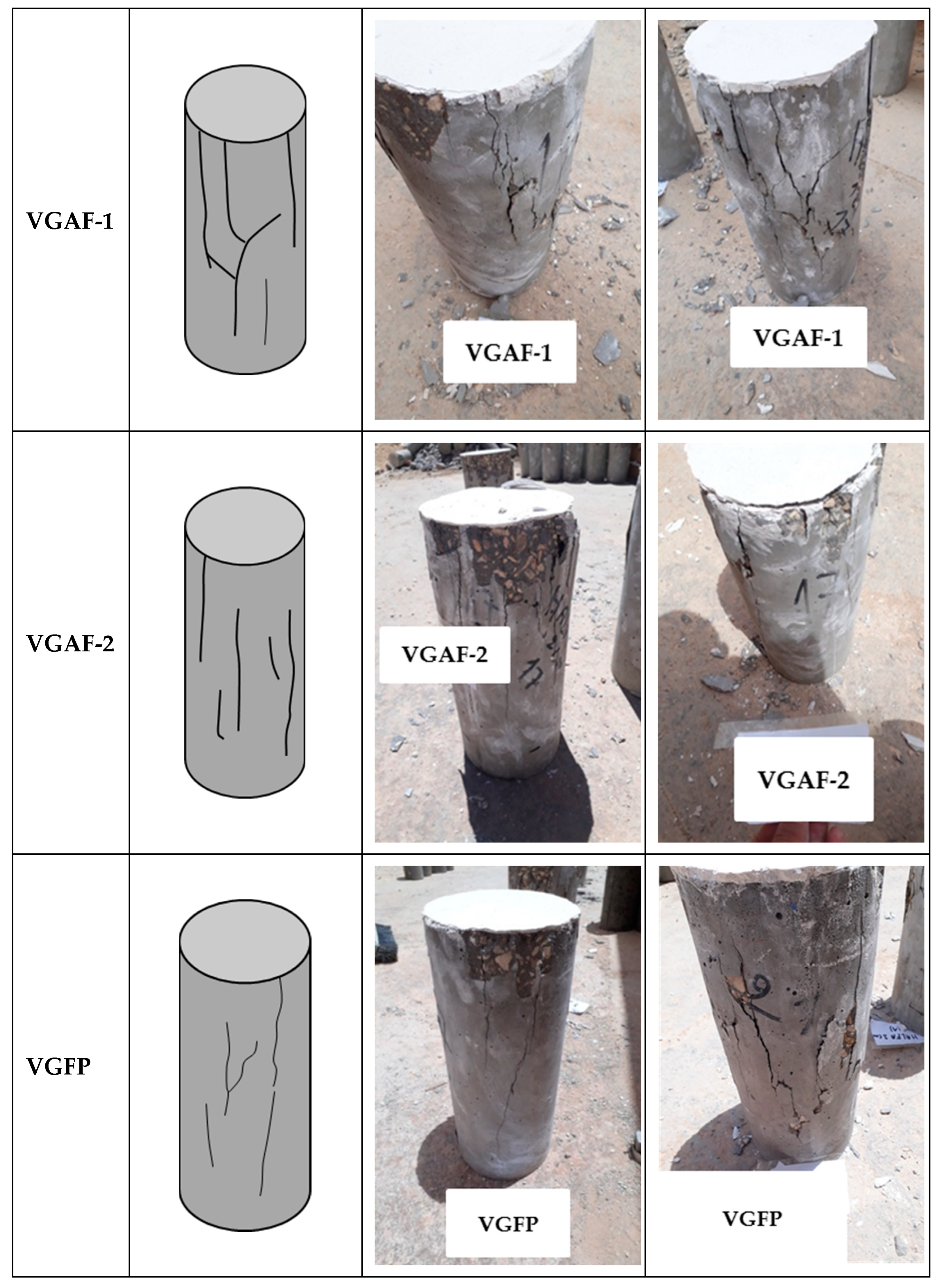
3.5.4. Confined Concrete with Vegetable Grids

Figure 17 shows the failure modes of SCC cylinders confined with various vegetable mesh grids. As shown in Figure 14, cracks first appear at both ends of the concrete sample under compression load. As the load increases, the crack at the end of the sample expands along the axial direction. When the peak stress is reached, cracks spread through the sample. Concrete cracks consist of vertical and inclined cracks. Cylinders confined with VGAF-1 showed a large number of cracks in comparison to VGAF-2 confined cylinders. This is probably due to the improvement in the bond between the VGAF-2 grids and the matrix, since the space between Alfa fibers increases.
The results of the failure mode per confinement type showed that the general aspect of the fracturing mode was similar for all the tested composites, without a total collapse of concrete cylinders. More macro-cracks were observed parallel to the main axis of loading, which differed significantly from the behavior of unconfined concrete, representing a conical failure pattern. It is noted that, the failure modes of concrete cylinders indicate a good adhesion between the cementitious matrix, aggregates, and grids. These findings highlight the beneficial effect of confinement on the ductility of SCC.
Using confinement grids in SCC prevents the development of lateral deformations of concrete and enhances mechanical performance under axial compression, allowing the transition from a brittle to a ductile failure mechanism.

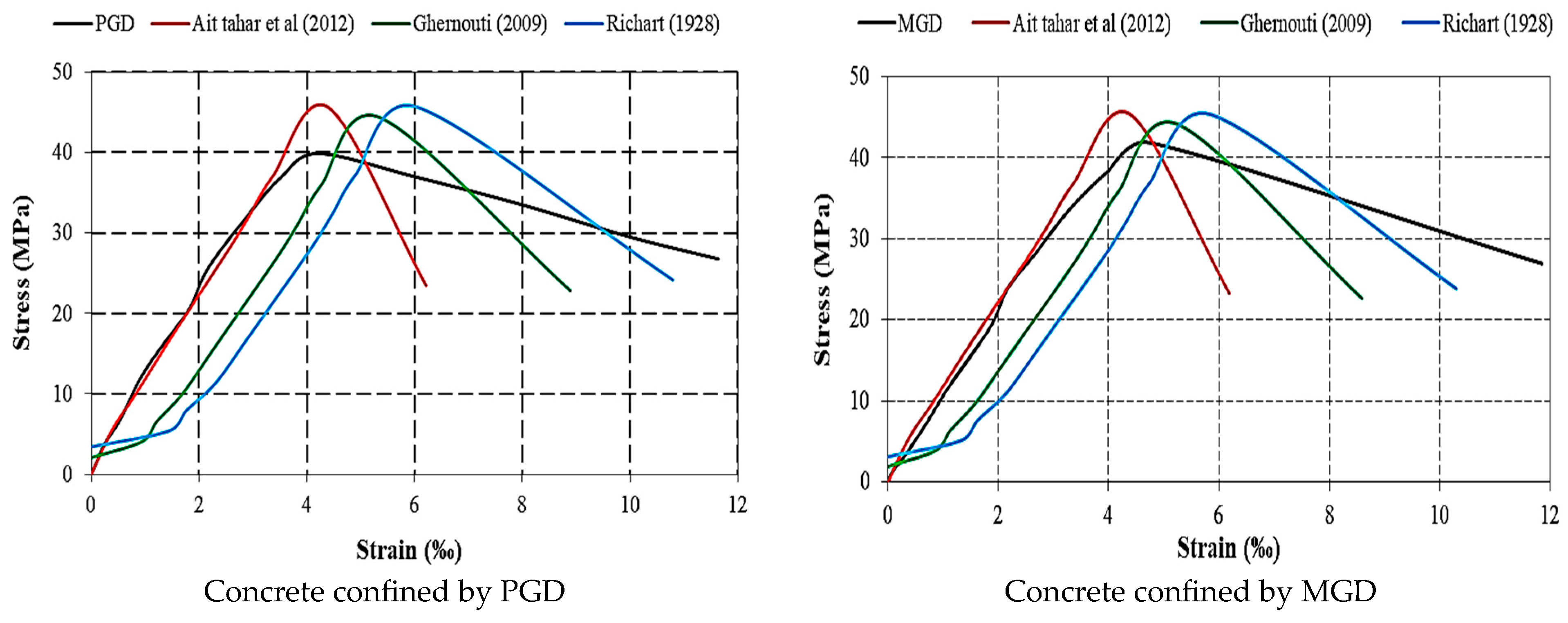
3.6. Comparison of Experimental and Analytical Confinement Models

The constitutive model of concrete plays an important role in the analysis of concrete structures. Since concrete is made of granular materials, its mechanical behavior depends intensively on volumetric pressure (confining stress). Therefore, the stress–strain behavior of confined and unconfined concrete is significantly different [43,44,45,46].
In the literature, several analytical and numerical models have attempted to represent the compressive stress–strain curves for confined concrete. Table 6 illustrates some of the proposed stress–strain confinement models to plot the stress–strain curve of confined concrete. These models vary in terms of complexity and calculation accuracy. Table 7 presents a comparisons of the experimental and analytical results for the three models chosen in this study: the Richart et al. [47], Ghernouti [48], and Ait tahar et al. [49] models, respectively. Figure 18 illustrates the comparison of the experimental and analytical stress–strain curves for MGD and PGD.
In order to verify the comparison of the experimental stress–strain curve with that given by the analytical models described in the literature, experimental and analytical results of the models were used [47,48,49]. The best mixtures were SCC confined by PGD and SCC confined by MGD. Figure 18 shows the experimental and analytical stress–strain curves obtained by each model. A comparison of the values of the experimental and analytical parameters is summarized in Table 7 for the selected mixtures. On the basis of the stress–strain curves, it was noted that there was good agreement between the experimental and numerical results in terms of the overall behavior of the confined cylinders under compression loading for both SCC confined by PGD and SCC confined by MGD. The models provide a very clear improvement in terms of ductility, with a plastic domain much larger than that of the experimental curve.
The maximum stresses from the experimental tests were slightly higher compared to those predicted by the numerical models. Indeed, each analytical model is limited by the conditions used and assumptions made by the authors, as well as by the experimental conditions, including the type of concrete and confinement technique, such as the grid type and mesh size and shape. However, a better correlation of the ultimate stress–strain curves is obtained by the Richart et al. model [47] when compared with the experimental values.

4. Conclusions

The development of new composite materials for sustainable confined structural elements using marble powder as a cement replacement and incorporating various types of grids with acceptable fresh and hardened properties has been examined in this paper. Based on the experimental results, the following conclusions can be made:
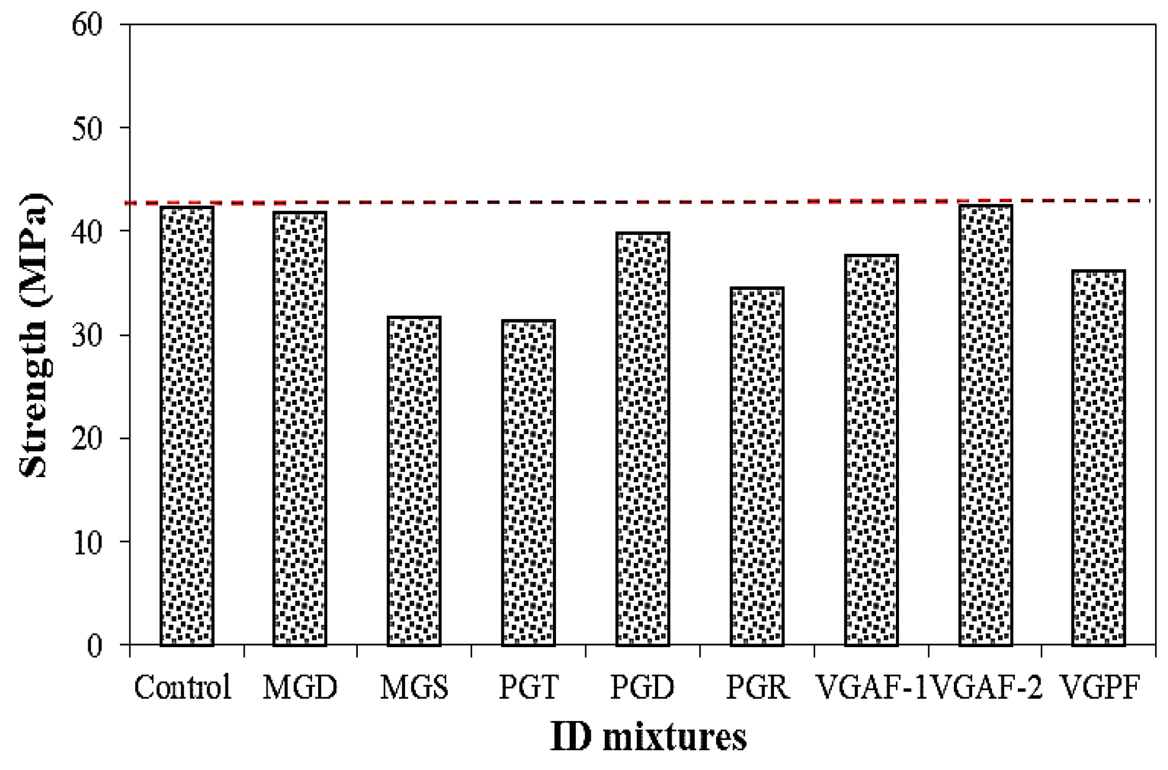
  • The ultimate compressive strength of SCC confined by different types of grids was almost closer to that of unconfined SCC. The only exception was SCC reinforced with alfa fiber grids (VGAF-2), where the resistance was slightly higher (42.57 vs. 42.25 MPa). It is therefore possible to improve the bearing capacity of SCC by incorporating grids of alfa fibers with a size of 20 × 20 mm (VGAF-2).
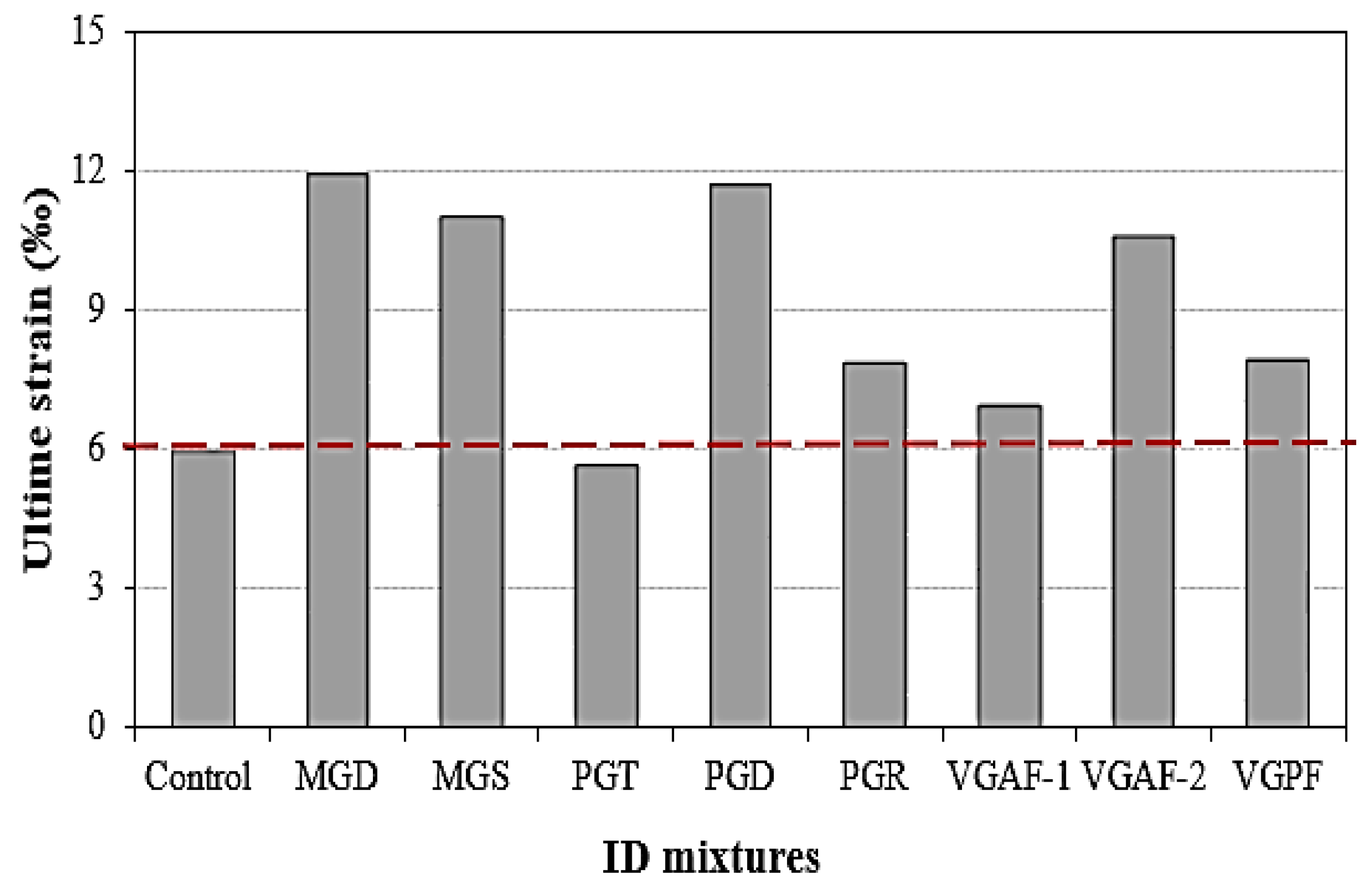
  • Using reinforcement grids with different types and geometries resulted in SCC with better ductility than the reference SCC mixture. For example, in SCC confined by PGD and PGR, there was an improvement in ductility, of about 96.45% and 32.77%, respectively. The specimens confined by MGD and MGS presented a significant increase in ductility, of about 100.33% and 85.13%, respectively. For SCC confined by vegetable grids (VGAF-1, VGAF-2, and VGPF), there was an improvement in the ductility, of approximately 16.89%, 78.37%, and 33.78%, respectively.
  • Mechanical behavior is largely influenced by the properties of the grid and the mesh shape. From the perspective of bearing capacity and ductility, the best performances occurred in SCC confined by a diamond grid shape.
  • The grid thickness, an often-overlooked parameter, exerts a pronounced influence on the effectiveness of the strengthening regimen. The high thickness of the grid influences the concrete–grid interface area and the concrete cover, which leads to poor adhesion, resulting in lowering mechanical performance.
  • Vegetable grids of alfa fibers with a large mesh (20 × 20 mm) offered better adhesion between concrete and grid than mesh with smaller sizes (10 × 10 mm), thus resulting in superior strength and ductility.
  • The rigidity was not affected by the type of grid materials because the modulus of elasticity of all types confined SCC studied was almost the same as that of unconfined SCC, with the exception of PGD confined SCC, which developed a superior elasticity modulus (13.74 GPa) compared to unconfined SCC (10.15 GPa).
  • Among the models that were selected, it was found that the Richart et al. [47] model provides good agreement between the experimental and analytical results in terms of the overall behavior.
  • The technique of lateral confinement may be used in the rehabilitation, strengthening, and reinforcement of weaker concrete structural members subjected to excessive axial loads, like columns, to enhance the mechanical properties of concrete and prevent sudden failure and therefore improve the service life of building structures. These innovative materials have found new applications in the rehabilitation, strengthening, and confinement of reinforced concrete members.

5. Recommendations for Future Research

This experimental work was limited to studying the influence of various types and shapes of grids as internal confinement on the mechanical properties and failure characteristics of confined SCC. Based on the needs highlighted in this study, further studies can be recommended as follows:
  • More research on the effect of grid mesh size on the mechanical behavior of SCC should be conducted.
  • Investigation regarding the adhesion between cement matrix and grids should be conducted using SEM.
  • Investigation of the economic feasibility of using various types of grids in SCC should be carried out.
  • The effect of eccentric and cyclic load on the mechanical properties of concrete should also be examined.
  • To better understand the mechanical behavior of cylinders confined using the proposed technique, it is necessary to test columns on a real scale.
  • Future work should validate the results obtained using the finite elements method.

Author Contributions

A.B.: Conceptualization, methodology, data curation, formal analysis, investigation, writing—original draft preparation; B.B.: Conceptualization, methodology, data curation, formal analysis, investigation, writing—original draft preparation; R.A.: Formal analysis, investigation, writing—review and editing; V.V.: Formal analysis, investigation, writing—review and editing. All authors have read and agreed to the published version of the manuscript.

Funding

This research received no external funding.

Data Availability Statement

The data is contained within the article.

Conflicts of Interest

The authors declare no conflicts of interest.

References

  1. Al-Kheetan, M.J.; Al-Tarawneh, M.; Ghaffar, S.H.; Chougan, M.; Jweihan, Y.S.; Rahman, M.M. Resistance of hydrophobic concrete with different moisture contents to advanced freeze–thaw cycles. Struct. Concr. 2020, 22, E1050–E1061. [Google Scholar] [CrossRef]
  2. Ghernouti, Y.; Rabehi, B.; Benhamna, A.; Mostefa, A.H. Strengthening of concrete beams by CFRP: Experimental study and finite element analysis. J. Build. Mater. Struct. 2014, 1, 47–57. [Google Scholar] [CrossRef]
  3. Ghernouti, Y. Design and Mechanical Analysis of Confinement of Cylindrical Concrete Elements with Mixed Reinforcements. Ph.D. Thesis, University of Boumerdes, Boumerdes, Algeria, 2009; p. 177. (In French). [Google Scholar]
  4. Li, W.; Li, W.; Lu, Y.; Hu, B.; Zhou, Y.; Wu, H.; Wang, P.; Ke, L.; Yu, J. Axial compressive behavior and failure mechanism of CFRP partially confined ultra-high performance concrete (UHPC). Constr. Build. Mater. 2024, 426, 136104. [Google Scholar] [CrossRef]
  5. Ancheeswari, M.; Jegan, J. Improvement on axial compressive strength of concrete cylinders using BFRP composites. J. Struct. Eng. 2018, 44, 545–551. [Google Scholar]
  6. Bouamra, Y.; Tahar, K.A. Mechanical performance of a confined reinforced concrete beam. Procedia Struct. Integr. 2017, 5, 155–162. [Google Scholar] [CrossRef]
  7. Daou, A.; Chehab, G.; Saad, G.; Hamad, B. Experimental and numerical investigations of reinforced concrete columns confined internally with biaxial geogrids. Constr. Build. Mater. 2020, 263, 120115. [Google Scholar] [CrossRef]
  8. Bastami, M.; Mousavi, A.E.; Abbasnejadfard, M. Evaluation of mechanical characteristics of high-strength reinforced concrete columns with hexagonal chicken wire mesh under cyclic loading. Int. J. Concr. Struct. Mater. 2022, 16, 1–14. [Google Scholar] [CrossRef]
  9. Donnini, J.; Spagnuolo, S.; Corinaldesi, V. A comparison between the use of FRP, FRCM and HPM for concrete confinement. Compos. Part B Eng. 2019, 160, 586–594. [Google Scholar] [CrossRef]
  10. Miyauchi, K.; Inoue, S.; Kuroda, T.; Kobayashi, A. Strengthening effects with carbon fiber sheet for concrete column. Proc. Jpn. Concr. Inst. 1999, 21, 1453–1458. (In Japanese) [Google Scholar]
  11. Ali Ahmed, C.; Ait Tahar, K. Behavior of concrete cylinder confined with helical composites Strips. Procedia Eng. 2015, 114, 157–164. [Google Scholar] [CrossRef]
  12. Chin, C.-L.; Ma, C.-K.; Tan, J.-Y.; Ong, C.-B.; Awang, A.Z.; Omar, W. Review on development of external steel-confined concrete. Constr. Build. Mater. 2019, 211, 919–931. [Google Scholar] [CrossRef]
  13. Desprez, C.; Mazars, J.; Kotronis, P.; Paultre, P.; Roy, N.; B-Trudeau, M. Cyclic model of concrete confined by TFC For circular reinforced concrete columns. In Proceedings of the 19th French Congress of Mechanics, Marseille, France, 24–28 August 2009. (In French). [Google Scholar]
  14. Xavier, R.; Mukilan, K. Experimental and numerical investigation of geosynthetic reinforced concrete structure. Int. J. Civ. Eng. 2024, 11, 145–152. [Google Scholar]
  15. Hadi, M.N.S.; Pham, T.M.; Lei, X. New method of strengthening reinforced concrete square columns by circularizing and wrapping with fiber-reinforced polymer or steel straps. J. Compos. Constr. 2013, 17, 229–238. [Google Scholar] [CrossRef]
  16. Hadi, M.N.S.; Zhao, H. Experimental study of high-strength concrete columns confined with different types of mesh under eccentric and concentric loads. J. Mater. Civ. Eng. 2011, 23, 823–832. [Google Scholar] [CrossRef]
  17. Saafi, M. Design and fabrication of FRP grids for aerospace and civil engineering applications. J. Aerosp. Eng. 2000, 13, 144–149. [Google Scholar] [CrossRef]
  18. Michael, A.P.; Hamilton, H.R., III; Ansley, M.H. Concrete confinement using carbon fibre reinforced polymer grid. ACI Spec. Publ. 2005, 230, 991–1010. [Google Scholar]
  19. Wu, G.; Wu, Z.S.; Luo, Y.B.; Jiang, J.B. Aseismic performance of circular concrete columns confined with FRP grids. J. Archit. Civil. Eng. 2007, 24, 39–44. (In Chinese) [Google Scholar]
  20. Choi, E.; Kim, J.-W.; Rhee, I.; Kang, J.-W. Behavior and modeling of confined concrete cylinders in axial compression using FRP rings. Compos. Part B Eng. 2014, 58, 175–184. [Google Scholar] [CrossRef]
  21. Heo, Y.-S.; Sanjayan, J.G.; Han, C.-G.; Han, M.-C. Construction application of Fibre/Mesh method for protecting concrete columns in fire. Constr. Build. Mater. 2011, 25, 2928–2938. [Google Scholar] [CrossRef]
  22. Lignola, G.P.; Prota, A.; Manfredi, G.; Cosenza, E. Nonlinear modeling of RC hollow piers confined with CFRP. Compos Struct. 2009, 88, 56–64. [Google Scholar] [CrossRef]
  23. Dai, J.-G.; Bai, Y.-L.; Teng, J.G. Behavior and modeling of concrete confined with FRP composites of large deformability. J. Compos. Constr. 2011, 15, 963–973. [Google Scholar] [CrossRef]
  24. Peled, A. Confinement of damaged and nondamaged structural concrete with FRP and TRC sleeves. J. Compos. Constr. 2007, 11, 514–522. [Google Scholar] [CrossRef]
  25. Rousakis, T.C. Hybrid confinement of concrete by fiber-reinforced polymer sheets and fiber ropes under cyclic axial compressive loading. J. Compos. Constr. 2013, 17, 732–743. [Google Scholar] [CrossRef]
  26. Rousakis, T.C. Elastic fiber ropes of ultrahigh-extension capacity in strengthening of concrete through confinement. J. Mater. Civ. Eng. 2014, 26, 34–44. [Google Scholar] [CrossRef]
  27. Paramasivam, P.; Ong, K.; Lim, C. Ferrocement laminates for strengthening RC T-beams. Cem. Concr. Compos. 1994, 16, 143–152. [Google Scholar] [CrossRef]
  28. Nassif, H.H.; Najm, H. Experimental and analytical investigation of ferrocement–concrete composite beams. Cem. Concr. Compos. 2004, 26, 787–796. [Google Scholar] [CrossRef]
  29. Abdullah, T.K. Shear strengthening of reinforced concrete columns using ferrocement jacket. Struct. J. 2001, 98, 696–704. [Google Scholar]
  30. Kumar, P.R.; Oshima, T.; Mikami, S.H.; Yamazaki, T. Studies on RC and ferrocement jacketed columns subjected to simulated seismic loading. Asian J. Civ. Eng. (Build. Hous.) 2007, 8, 215–225. [Google Scholar]
  31. Bansal, P.P.; Kumar, M.; Kaushik, S.K. Effect of wire mesh orientation on strength of beams retrofitted using Ferrocement jackets. Int. J. Eng. 2008, 2, 8–19. [Google Scholar]
  32. Makki, R.F. Response of reinforced concrete beams retrofitted by ferrocement. Int. J. Sci. Technol. Res. 2014, 3, 27–34. [Google Scholar]
  33. Bentayeb, F.; Tahar, K.A.; Chateauneuf, A. New technique for reinforcement of concrete columns confined by embedded composite grid. Constr. Build. Mater. 2008, 22, 1624–1633. [Google Scholar] [CrossRef]
  34. Ait tahar, K.; Bahar, R. Influence of the dimensions of the mesh of the fiber grid reinforcement of composite materials. Key Eng. Mater. 2013, 550, 9–16. [Google Scholar] [CrossRef]
  35. Boukhelkhal, A.; Azzouz, L.; Belaïdi, A.S.E.; Benabed, B. Effects of marble powder as a partial replacement of cement on some engineering properties of self-compacting concrete. J. Adhes. Sci. Technol. 2016, 30, 2405–2419. [Google Scholar] [CrossRef]
  36. Boukhelkhal, A.; Azzouz, L.; Benabed, B.; Belaïdi, A.S.E. Strength and durability of low-impact environmental self-compacting concrete incorporating waste marble powder. J. Build. Mater. Struct. 2017, 4, 31–41. [Google Scholar] [CrossRef]
  37. EFNARC. Specification and Guidelines for Self-Compacting Concrete; European Federation of Producers and Applicators of Specialist Products for Structures, EFNARC: Norfolk, VA, USA, 2005; p. 32. [Google Scholar]
  38. NF EN 12390; Testing Hardened Concrete Part 3: Compressive Strength of Test Specimens. AFNOR: Paris, France, 2019.
  39. Baron, J. Resistance to Crack Propagation: Hydraulic Concrete; ENPC: Paris, France, 1982. [Google Scholar]
  40. Gorisse, F. Concrete Testing and Control; Edition Eyrolles: Paris, France, 1978. (In French) [Google Scholar]
  41. Mindess, S.; Young, J.F.; Darwin, D. Concrete, 2nd ed.; Pearson Education Inc.: London, UK, 2003. [Google Scholar]
  42. Thermou, G.E.; Katakalos, K.; Manos, G. Concrete confinement with steel-reinforced grout jackets. Mater. Struct. 2014, 48, 1355–1376. [Google Scholar] [CrossRef]
  43. Binici, B. An analytical model for stress–strain behavior of confined concrete. Eng. Struct. 2005, 27, 1040–1051. [Google Scholar] [CrossRef]
  44. Mander, J.B.; Priestley, M.J.N.; Park, R. Theoretical stress-strain model for confined concrete. J. Struct. Eng. 1988, 114, 1804–1826. [Google Scholar] [CrossRef]
  45. Marwan, N.Y.; Maria, Q.F.; Ayman, S.M. Stress-strain model for concrete confined by FRP composites. Composites Part B Eng. 2007, 38, 614–628. [Google Scholar]
  46. Harajli, M.H. Axial stress–strain relationship for FRP confined circular and rectangular concrete columns. Cem. Concr. Compos. 2006, 28, 938–948. [Google Scholar] [CrossRef]
  47. Richart, F.; Brandtzaeg, A.; Brown, R.L. A Study of the Failure of Concrete Under Combined Compressive Stresses; University of Illinois, Engineering Experimental Station: Urbana, IL, USA, 1928; Bulletin N° 185, 104. [Google Scholar]
  48. Ghernouti, Y.; Ait Tahar, K. Multiple confinements of concrete columns by various embedded composite grids. J. Reinf. Plast. Compos. 2009, 28, 1495–1507. [Google Scholar] [CrossRef]
  49. Tahar, K.A.; Taouche, F.; Bouamra, Y. Parametric Analysis of the models of confinement of the concrete column. Key Eng. Mater. 2012, 498, 1–14. [Google Scholar] [CrossRef]
  50. Fardis, M.N.; Khalili, H.H. FRP-encased concrete as a structural material. Mag. Concr. Res. 1982, 34, 191–202. [Google Scholar] [CrossRef]
  51. Karbhari, V.; Eckel, D.; Tunis, G. Strengthening of Concrete Column Stubs through Resin Infused Composite Wraps. J. Thermoplast. Compos. Mater. 1993, 6, 92–107. [Google Scholar] [CrossRef]
  52. Saafi, M.; Toutanji, A.H.; Li, Z. Behaviour of Concrete Columns Confined with Fibre Reinforced Polymer Tubes. ACI Mater. J. 1999, 96, 500–509. [Google Scholar]
Figure 1. Particle size distribution of aggregates.
Buildings 15 01286 g001
Figure 2. Tensile test on grids.
Buildings 15 01286 g002aBuildings 15 01286 g002b
Figure 3. Laboratory experimental program.
Buildings 15 01286 g003
Figure 4. Laboratory fresh tests on SCC mixtures: (a) slump flow, (b) V-funnel, (c) L-box, and (d) sieve segregation.
Buildings 15 01286 g004
Figure 5. Procedure of grid confinement.
Buildings 15 01286 g005
Figure 6. Testing procedure.
Buildings 15 01286 g006
Figure 7. Stress–strain curve of control SCC (unconfined).
Buildings 15 01286 g007
Figure 8. Stress–strain curve of control SCC and SCC confined by plastic grids.
Buildings 15 01286 g008
Figure 9. Stress–strain curve of control SCC and SCC confined by metal grids.
Buildings 15 01286 g009
Figure 10. Stress–strain curve of control SCC and SCC confined by vegetable grids.
Buildings 15 01286 g010
Figure 11. Strength of different mixtures studied.
Buildings 15 01286 g011
Figure 12. Ultimate strain of different mixtures studied.
Buildings 15 01286 g012
Figure 13. Elasticity modulus of different SCC mixtures.
Buildings 15 01286 g013
Figure 14. Failure mode of unconfined SCC.
Buildings 15 01286 g014
Figure 15. Failure mode of confined concrete with plastic grids.
Buildings 15 01286 g015
Figure 16. Failure mode of confined concrete with metallic grids.
Buildings 15 01286 g016
Figure 17. Failure mode of confined concrete with vegetable grids.
Buildings 15 01286 g017
Figure 18. Comparison of the experimental and analytical stress–strain curves of confined SCC [47,48,49].
Buildings 15 01286 g018
Table 1. Chemical composition and physical properties of cement and marble powder.
Chemical CompositionPhysical Properties
Element (%)SiO2CaOMgOAl2O3Fe2O3SO3K2OTiO2Na2OP2O5Loss IgnitionSpecific DensityFineness (cm2/g)
Cement20.1463.472.123.714.742.670.470.210.690.061.723.13300
MP0.4256.010.120.130.060.010.010.010.430.0342.782.73600
Table 2. Physical properties of aggregates.
AggregateSand 0/5Gravel 3/8Gravel 8/15
Absorption coefficient (%)1.164.853.48
Specific density2.472.52.5
Bulk density1.511.291.24
Property coefficient (%)90.28--
Fineness modulus1.85--
Table 3. Properties of the grids used.
Grid PropertiesPhotos
Plastic grids of triangular mesh (PGT)
Dimensions of mesh: 5 × 5 × 5 mm
Thickness: 5 mm
Weight: 3037.26 g/m2
Number of meshes: 44,627 mesh/m2
Breaking load: 20 N
Strain at rupture: 1.24 mm/mm
Modulus of elasticity: 2 MPa
Buildings 15 01286 i001
Plastic grids of diamond mesh (PGD)
Dimensions of mesh: 3 × 3 mm
Thickness: 2 mm
Weight: 331.5 g/m2
Number of meshes: 35,420 mesh/m2
Breaking load: 50 N
Modulus of elasticity: 10 MPa
Buildings 15 01286 i002
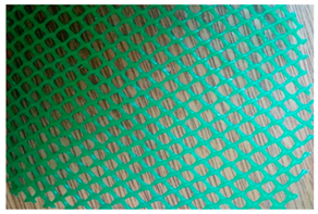
Plastic grids of rectangular mesh (PGR)
Dimensions of mesh: 3 × 2 mm
Thickness: 0.5 mm
Weight: 331.5 g/m2
Number of meshes: 131,794 mesh/m2
Breaking load: 8 N
Strain at rupture: 0.875 mm/mm
Modulus of elasticity: 86 MPa
Buildings 15 01286 i003
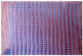
Metallic grids of diamond mesh (MGD)
Dimensions of mesh: 5 × 5 mm
Thickness: 1 mm
Weight: 407.5 g/m2
Number of meshes: 16,000 mesh/m2
Breaking load: 90 N
Strain at rupture: 0.123 mm/mm
Modulus of elasticity: 71 MPa
Buildings 15 01286 i004
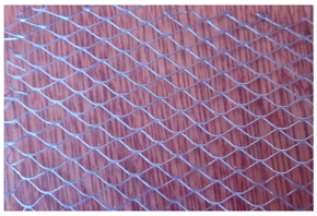
Metallic grids of square mesh (MGS)
Dimensions of mesh: 1.5 × 1.5 mm
Thickness: 0.5 mm
Weight: 355.5 g/m2
Number of meshes: 376,584 mesh/m2
Breaking load: 100 N
Strain at rupture: 0.384 mm/mm
Modulus of elasticity: 47 MPa
Buildings 15 01286 i005
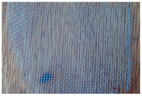
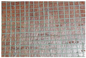
Vegetable grids of alfa fibers (VGAF-1)
Square mesh
Dimensions of mesh: 10 × 10 mm
Thickness: 3 mm
Weight: 248 g/m2
Number (mesh): 9801 mesh/m2
Buildings 15 01286 i006
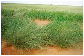
Vegetable grids of alfa fibers (VGAF-2)
Square mesh
Dimensions of mesh: 20 × 20 mm
Thickness: 3 mm
Weight: 124 g/m2
Number (mesh): 2451 mesh/m2
Buildings 15 01286 i007
Illustration of alfa fibers (Stipa Tenacissima)
Buildings 15 01286 i008
Vegetable grids of date palm fibers (VGPF)
Tissue mesh
Thickness: 4 mm
Weight: 347.13 g/m2
Breaking load: 72 N
Strain at rupture: 0.024 mm/mm
Modulus of elasticity: 67 MPa
Buildings 15 01286 i009
Buildings 15 01286 i010
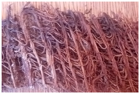
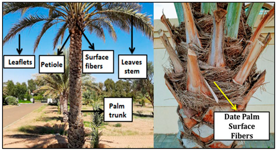
Illustration of date palm fibers
Table 4. SCC mix proportions and fresh properties.
MaterialsWeight (kg)Test on Fresh SCCResultClass
(EFNARC) [37]
Limit Values
OPC412.54Slump flow diameter (mm)760 SFR3760–850
Marble powder39.92V-funnel flow time (s)9 VS2/VF29–25
Sand 0/5803.20L-box blocking ratio (%)83PA2>80
Gravel 8/15534.08Segregation index (%)10SR2<15
Gravel 3/8263.25
Water220.39
Superplasticizer4.07
Water/binder (w/b)0.4
Table 5. Strength gain (SG) and ductility gain (DG).
Strength Gain (%)Ductility Gain (%)Modulus of Elasticity E (GPa)
Unconfined concrete------10.14
Confined concrete
Plastic gridsPGT−25.96−4.8910.79
PGD−5.6396.4513.74
PGR−18.4132.7710.32
Metal gridsMGD−0.92100.3311.20
MGS−24.8585.1310.74
Vegetable gridsVGAF-1 (Alfa)−10.6716.899.82
VGAF-2 (Alfa)0.7578.3711.64
VGPF (palm)−14.3133.7811.27
Table 6. Some models of confined concrete.
ReferenceConcrete StrengthConcrete Strain
Richart et al. [47] f c c = f c o + K 1 f L
K 1 = 4.1
ε c c = ε c o 1 + K 2 f L f c o
K 2 = 5 K 1
Ghernouti [48] f c c = f c o + K 1 f L
K 1 = 2.5
ε c c = ε c o 1 + K 2 f L f c o
K 2 = 5 K 1
Ait tahar et al. [49] f c c = f c o 1 + 1.33 f L f c o 0.72 ε c c = ε c o 1 + ( 1.33 ) 0.75 f L f c o
Fardis and Khalili [50] f c c f c o = [ 1 + 4.4 2 f f D . f c o . t f ] ε c c = ε c o + 0.001 ( E f D . f c o . t f )
Karbahari and Eckel [51] f c c = f c o 1 + 2.1 f L f c o 0.87 ε c c = 0.002 1 + 5 ( 2 t f . f f D . f c o )
Saafi et al. [52] f c c f c o = [ 1 + 2.2 f L f c o 0.84 ] ε c c = ε c o [ 1 + ( 537 ε f + 2.6 ) ( f c c f c o 1 ) ]
where fc: Compressive strength of concrete; εc: Axial strain of concrete; fco: Compressive strength of unconfined concrete; εco: Axial strain in strength of unconfined concrete; fu: Ultimate strength of unconfined concrete; εu: Ultimate axial strain of unconfined concrete; f c u : Ultimate strength of confined concrete; ε c u : Ultimate axial strain of confined concrete; f c c : Maximal strength of confined concrete; ε c c : Axial strain in strength of confined concrete; ε f : Ultimate strain of grids; fL: Lateral confinement pressure; ff: Ultimate tensile strength of grids; tf: thickness of grids; D: Diameter of concrete cylinder; Ef: Deterioration rate of confined concrete; K1, K2: Empirically determined confinement coefficients.
Table 7. Comparison of experimental and analytical results of SCC confined by PGD and MGD.
Parameters of ModelExperimental ValueAit tahar et al. [49]Ghernouti [48]Richart et al. [47]
K//2.54.1
f c o (MPa)42.25 ///
Analytical value
PGD
f c c (MPa)39.8745.5744.3345.66
ε c c (‰)4.194.415.366.04
f c u (MPa)26.7823.4822.8424.17
ε c u (‰)11.636.218.8910.79
MGD
f c c (MPa)41.8645.3344.1245.32
ε c c (‰)4.754.395.255.86
f c u (MPa)26.9323.2822.6323.83
ε c u (‰)11.866.188.5910.30
Disclaimer/Publisher’s Note: The statements, opinions and data contained in all publications are solely those of the individual author(s) and contributor(s) and not of MDPI and/or the editor(s). MDPI and/or the editor(s) disclaim responsibility for any injury to people or property resulting from any ideas, methods, instructions or products referred to in the content.

