1. Introduction
Globally, the construction sector has a substantial environmental impact. For example, it consumes 34% of the total energy during the material production and building operational phases, contributing significantly to environmental degradation. The sector is also responsible for producing 37% of global CO
2 emissions [
1]. Moreover, construction and demolition waste (CDW) represents the largest fraction of waste, accounting for between 30% to 40% of total solid waste [
2]. This high level of waste generation stems from the industry’s reliance on a linear economic model based on the unsustainable principle of take, make, and dispose [
3]. If this model remains unchanged, projections indicate that global material consumption in cities could soar from 40 billion tons in 2010 to 90 billion tons by 2050, continuing along current trends [
4].
Acknowledging the need for a radical change in approach, the Ellen MacArthur Foundation [
5] describes a new model: the circular economy as “an industrial economy that is restorative or regenerative by intention and design”. This objective is achieved through sustainable design, consistent upkeep, repair, reuse, remanufacturing, refurbishment, and recycling [
6]. This approach could reduce global CO
2 emissions from materials by 38%, or two billion tons, by 2050, primarily due to reduced demand for steel, aluminum, cement, and plastic [
7]. Wood emerges as a highly valuable renewable resource within this approach, particularly when sustainably harvested. By aligning with circularity principles, timber meets ecological criteria and offers high potential for reuse and recycling at the end of a building’s lifespan [
8].
Wood captures carbon dioxide (CO
2) during its growth and retains this carbon throughout its use in construction [
9]. However, in a linear economy model, where timber is often considered a single-use product, most of the material is incinerated for energy generation after demolition [
1]. It is crucial to consider how to extend the durability of recovered timber and find sustainable ways for its reuse, mitigating the environmental impact.
In recent decades, aligned with sustainability objectives, architectural and construction design approaches, principles, and methodologies have been developed to facilitate the recovery of materials at the building’s end of life. Among them, Design for Disassembly (DfD) stands out as a design strategy that aims to replace the demolition phase of the life cycle with a disassembly phase. This approach allows the building’s components to be recovered, reused, and recycled, thereby reducing solid waste generation [
10]. Designing constructive solutions for reuse of their components ensures that they can be reintroduced at their maximum value, reducing the need for new primary materials.
Furthermore, industrialized timber construction systems, especially 2D panelized frame, exhibit an inherent adaptability that allows for reconfiguration without demolition. The standardization of their components, which are easily assembled, presupposes efficient disassembly, contingent upon the nature of the connections between elements [
7]. However, it is crucial to consider the longevity of the various layers that make up the construction components [
8] and their interconnection. This consideration ensures the viability of refurbishing the complete panel for reuse, whether in its original location or a new building.
This study aims to evaluate the disassemblability of prefabricated light timber frame walls by quantifying their recoverability, reusability, and recyclability down to the product level. For this purpose, a full-scale model was built to represent a construction system with continuous exterior insulation, commonly used in Quebec, Canada. The objective is to identify and analyze the critical factors, both drivers and barriers, that affect the recovery of their components. Exploring observations from the disassembly of structures that do not initially consider the principles of Design for Disassembly (DfD) could inform and improve future design practices. Additionally, the analysis emphasizes considering the two-dimensional panel not only as an interlinked element with others but also as a network of interconnections among its various components.
Based on the proposed analysis, it is hypothesized that the absence of DfD strategies in the panelized frame system significantly limits the ability to recover components effectively. This limitation manifests in the prolonged time required to recover materials in optimal condition, making it impractical for real-world applications.
The relevance of this research lies in its potential to promote sustainability in the construction industry, as it is intrinsically aligned with the guidelines of the circular economy. Given the projected substantial increase in global material consumption, the consequent rise in construction and demolition waste (CDW), and the resulting environmental impact [
5], it becomes imperative to explore adopting principles related to DfD. This strategy represents a crucial opportunity to mitigate solid waste generation and decrease the demand for primary virgin materials. This study not only aims to illustrate the barriers affecting the disassemblability of 2D panelized frame by evaluating a traditional prefabricated system but also, through this analysis, seeks to facilitate the identification of challenges to integrate them into practice effectively. In doing so, a significant reduction in CO
2 emissions associated with producing new materials is projected, thus promoting a transition towards more regenerative and environmentally responsible construction practices.
1.1. Design for X
Various methodologies aim toward maximizing resource efficiency and minimizing waste, spanning from the design phase to the end of a building’s life cycle [
11,
12,
13]. From the early stages of building conception, the aim is to enable components and materials to be easily recovered and reused in new construction [
3], thus prolonging their service life and reducing the need for virgin resources [
14,
15].
In this regard, eco-design methodologies in construction seek to integrate principles that allow for the design of adaptable buildings that can be easily dismantled at the end of their life cycle [
16]. Similarly, the term “Design for X” (DfX) additionally refers to design approaches focused on end-of-life scenarios of a product, where X indicates the specific goal, such as recycling or disassembly [
16].
This framework includes various strategies: Design for Reuse, Design for Adaptability, and Design for Deconstruction. For example, Design for Reuse focuses on standardizing material dimensions to maximize the potential for multiple reuse cycles of components and [
13] ensuring that recovered parts fit seamlessly into new designs with minimal adjustments [
17]. Meanwhile, Design for Adaptability (DfA) emphasizes the ability of buildings to adjust to changing conditions and user needs over time, enhancing their longevity and flexibility [
18,
19].
However, successfully implementing DfX in construction requires acknowledging the inherent complexity of buildings, which consist of diverse components with varying lifespans, necessitating careful consideration of how these principles are applied [
16].
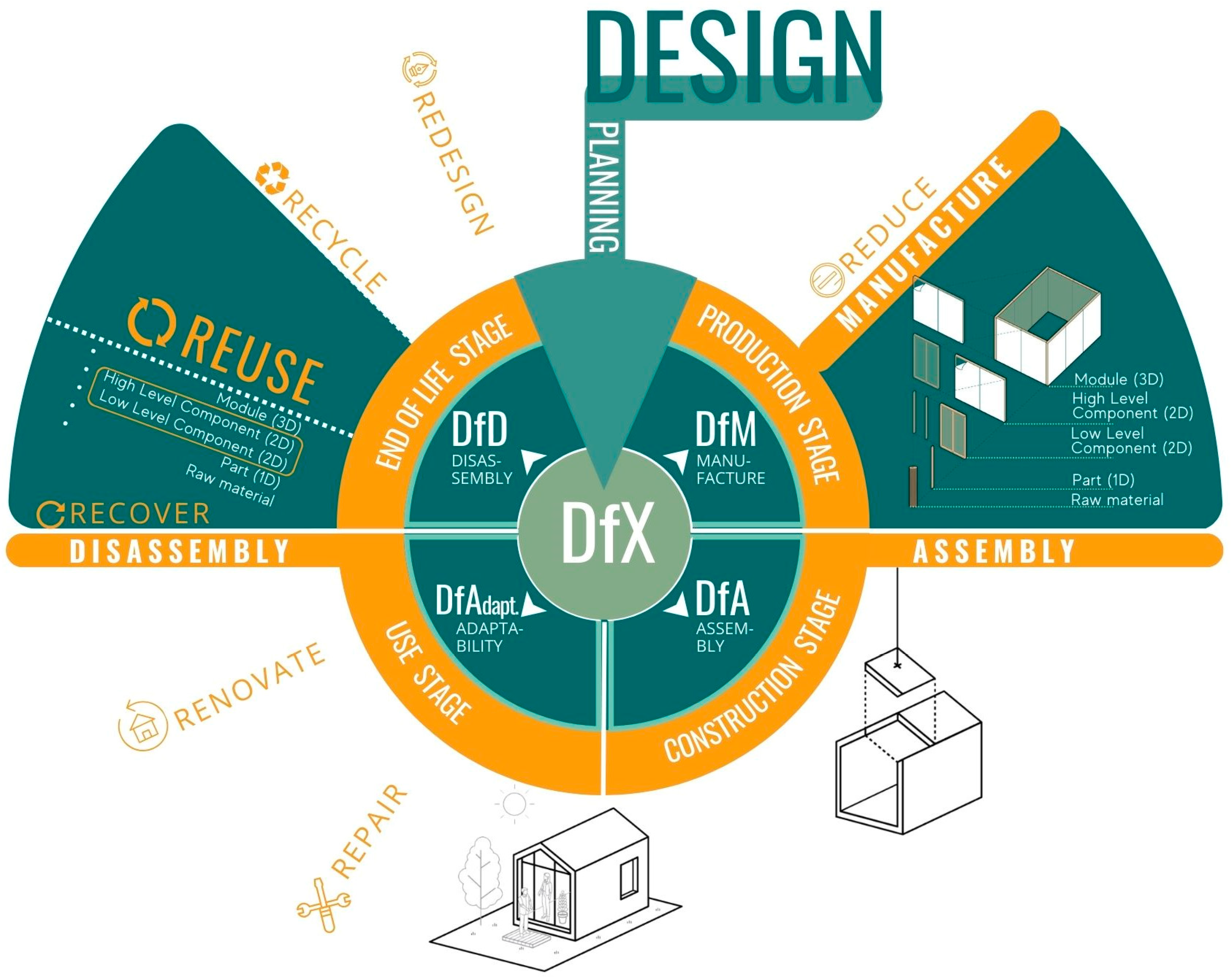
Figure 1 illustrates a series of DfX methodologies and the impact of each on the different stages of an industrialized building’s life cycle. This study, however, focuses on Design for Disassembly, which aims to facilitate the recovery and reuse of components at the end of the building’s life cycle, while also examining its relationship with Design for Manufacture and Assembly to enhance construction and assembly processes.
1.2. Design for Disassembly
In the context of DfX methodologies, Design for Disassembly (DfD) emerges as one of the key design strategies that establish the foundations for the circular economy within the construction sector. In the literature, the terms Design for Disassembly and Design for Deconstruction are often used interchangeably, reflecting the shared objectives of these approaches [
13]. As highlighted by Durmisevic et al. [
20], DfD plays a crucial role in facilitating the recovery and reuse of components at the end of a building’s life cycle, thus enhancing resource efficiency.
DfD, originally developed as an extension of Design for Assembly, is a strategy aimed at optimizing assembly sequences for mechanical and electronic products [
21]. This methodology is considered fundamental to circularity and is key to enabling circular processes within the construction sector [
22]. Crowther [
3], a pioneer in introducing the term and concept of DfD, identified three essential principles: open building design, which incorporates disassembly from the design phase; the use of structural grids; and lightweight structural elements grids [
3,
23].
In the early discussions on Design for Disassembly (DfD), the concept of “shearing layers” was introduced, emphasizing the independence of the various building layers. Crowther [
3] proposed that buildings can be understood as a series of interrelated layers, such as structure, cladding, and services, each with a specific lifespan. This approach allows components to be updated, repaired, and replaced according to their life cycle duration [
24], facilitating maintenance and adaptability in construction [
2].
Later, Crowther [
3] expanded on this idea by noting that designing and constructing in a stratified manner extends a building’s lifespan. Shearing layers, which include elements of the building envelope system, such as thermal, waterproofing, and structural components [
7], should be organized so that shorter-lived layers are placed closer to the surface. To enhance flexibility and adaptability to future requirements, long-lasting components should be designed to allow for easy replacement of shorter-lived elements [
2]. This arrangement enables the application of flexible deconstruction strategies based on each layer’s durability [
25]. Consequently, the different layers must be designed to be disassembled to ensure the building’s adaptability and future readiness [
10], supporting an assembly and disassembly approach where components are designed to be easily disassembled and reused [
26].
Subsequent studies expanded on these principles, adding that the use of prefabricated construction systems and standardization facilitate disassembly and contribute to a circular economy [
2,
13]. In this context, approached from a structural design perspective, reversible connections are crucial to separating the shearing layers [
27] characterized by their ease of disassembly and the potential for reuse, both of the connections and the components attached [
18]. This feature allows for disassembly and reassembly during maintenance and repair without significant damage [
20], enabling the reuse of components in new locations or building modifications, making it possible to use them in other parts of the same building or in other buildings [
18].
Regarding the connections between layers, these must be designed for efficient disassembly, especially at the intersections of components with different life expectancies. Evaluating the lifespan of these layers will enable the designer to identify when and where to implement strategies for disassembly [
3] as well as emphasize the need for a reduction in the number and variety of connections [
23,
28]. Furthermore, gravity connections rely on the self-weight of the components to keep them in place. These connections act just for shear stresses (without bending moment) [
20] and are particularly useful in circular constructions, where building flexibility is critical. They facilitate the assembly and disassembly of components and can be integrated within a timber frame or used to connect new structural elements to existing frames [
10].
Recognizing the relevance of DfD in the transition towards more circular buildings, ISO 20887:2020, sustainability in buildings and civil engineering works—design for disassembly and adaptability—principles, requirements and guidance, was established. The standard defines guidelines for Design for Disassembly and Adaptability (DfD/A) oriented towards sustainability in construction [
29]. This design approach helps buildings maintain their functionality and safety over the long term in different scenarios. This standard not only addresses disassembly but also incorporates adaptability as a fundamental component, thus promoting buildings with an extended lifespan and the ability to respond to various changing conditions. According to ISO 20887:2020, buildings designed under the DfD/A guidelines exhibit increased resilience and are projected to adapt to external factors such as demographic, social, economic, and technological changes, including those effects derived from climate change [
30].
1.3. Design for Manufacture and Assembly
Within the DfX methodologies, another notable life cycle method is Design for Manufacturing and Assembly (DfMA) [
27]. This strategy consists of designing products and systems to be easy to manufacture, transport, and assemble [
8]. It includes optimizing component fasteners to ensure assembly is quick and error-free [
27]. Therefore, it is essential to know the components available in the supply chain, the capabilities of the manufacturing process, the logistics involved, and the possible constraints at the installation site [
31].
DfMA is situated within the comprehensive framework of industrialization, understood as a complete system aimed at transferring construction activities to a controlled manufacturing environment, thereby facilitating off-site construction. This broad system enables greater quality control and production efficiency, with the DfMA methodology playing a crucial role in optimizing projects by significantly reducing assembly time and minimizing errors during installation [
32].
In this conceptual framework, standardization, as a principle established in ISO 20887, emphasizes that design should consider optimizing materials through modular or prefabricated construction [
29]. Prefabrication, in turn, reduces on-site work, allowing for greater control and conformity of components. Additionally, the interchangeability of standardized components facilitates simplicity, adaptability, and reuse [
30]. The selection of standard-sized materials further supports reuse and minimizes on-site cutting waste [
31].
The concept of prefabrication has historically been used to create buildings that are easy to assemble, and with potential to be disassembled, and maintain [
13]. It is especially suitable for incorporating disassemblability from the beginning of the design, as it is manufactured in a different location from the construction site and assembled quickly on-site without generating waste [
18].
Prefabrication has the potential to decrease production time and material consumption, promoting a circular sector [
31]. It ensures the recovery, recycling, and optimization of construction time, improving building adaptability, assembly, and disassembly [
2]. Additionally, it minimizes waste flows [
33], reduces environmental impacts [
31], lowers construction costs [
13], and enhances productivity [
31]. The increase in the prefabrication level facilitates assembly processes and improves the quality and conformity of components due to factory quality controls [
34], making their handling easier and faster [
3]. Prefabricated buildings allow for partial disassembly during their use phase, facilitating maintenance tasks without significantly altering the structure [
31]. This is due to modular and standardized components with reversible connections, which can be disassembled and reassembled [
18].
Roxas et al. [
27] discuss the benefits of jointly applying DfMA and DfD. While they do not provide a detailed convergence of both methodologies, they emphasize that the use of prefabricated panels within industrialized construction aligns well with DfD principles. This alignment is achieved as these panels can be readily assembled and disassembled, allowing their components to be reused or recycled rather than discarded [
31]. Thus, integrating both approaches spans the entire life cycle, from construction to disassembly, promoting a more efficient and environmentally friendly process [
27].
In summary, the reviewed literature states that DfD is one of the key strategies of the circular economy in construction [
3,
27,
35], showing a framework that establishes design principles to be applied in the early stages of a building [
36]. Recent studies delve into reversible connections [
18], highlighting that prefabricated constructions have a greater capacity for disassembly for subsequent reuse of their parts or components [
10,
31,
37]. Despite advances in DfD theory and practice, there is a lack of empirical studies investigating determining factors in prefabricated light timber frame systems that enable their disassembly and subsequent reuse, whether of the entire construction element or its individual components.
2. Materials and Methods
At the Research Center on Renewable Materials (CRMR), Université Laval, in Quebec City, QC, Canada, CA, a full-scale model was assembled and disassembled in the laboratories. Using an experimental research method based on a detailed evaluation of the characteristics or properties of components [
38], aspects of recoverability, reusability, and recyclability have been analyzed. Therefore, a corner junction of two exterior walls of a light timber frame single house was reproduced. This construction system model, widely used in Quebec and North America, adheres to the guidelines of Novoclimat, a Quebec government program established in 1999 to enhance energy efficiency, comfort, and air quality in new residential buildings [
39]. It establishes energy performance standards and provides certification for energy-efficient home construction.
A basic prefabrication was carried out in a controlled environment, adopting a level 1 of prefabrication in the full-size scale model. According to Hong et al. [
1], level 1 of prefabrication is characterized by including only individual construction elements, such as beams, columns, or the basic structure of the panel. The adoption of a higher level of prefabrication has other implications, such as greater complexity in manufacturing, but with the potential to improve efficiency and reduce on-site assembly time.
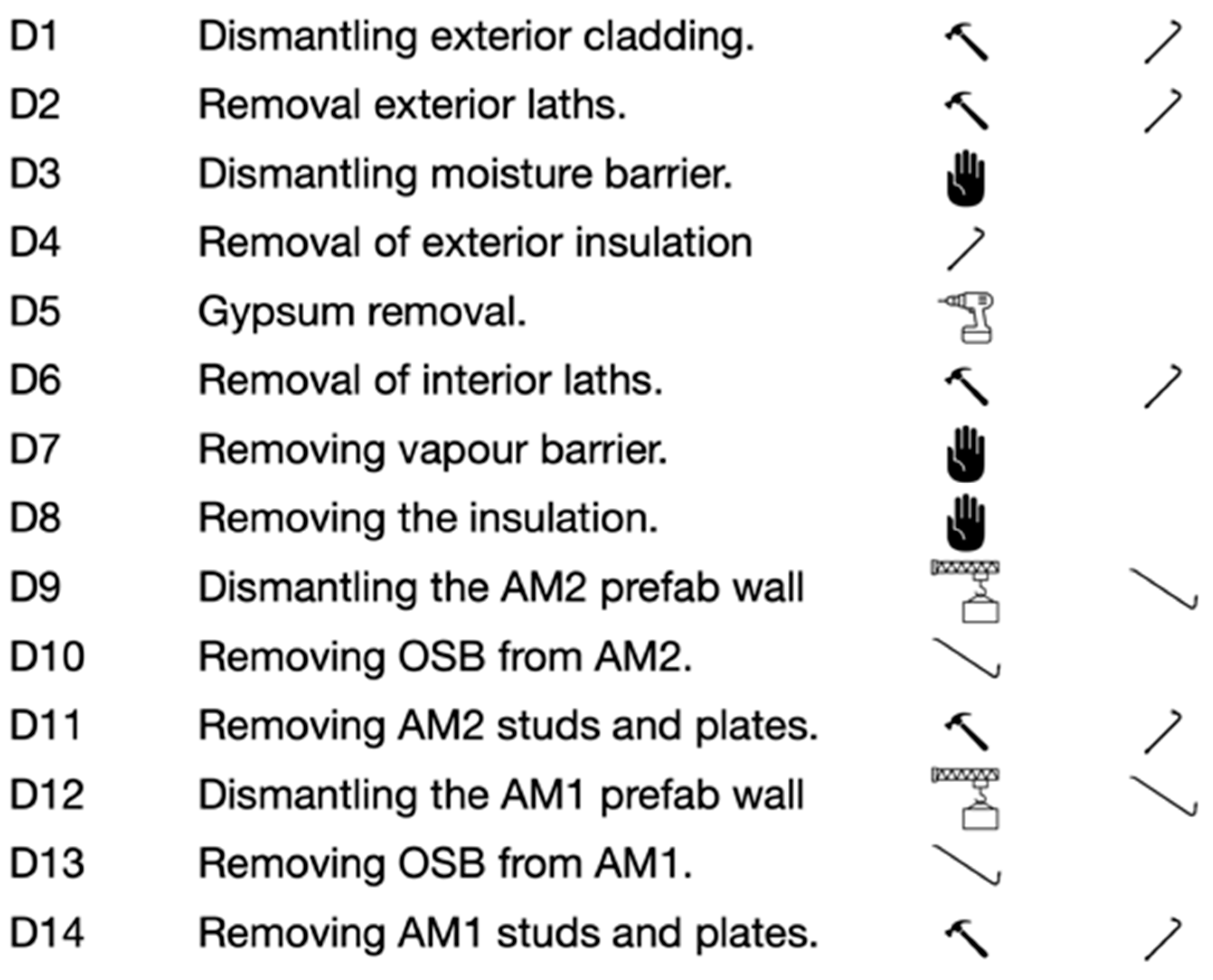
The stages of the laboratory test (assembly and disassembly) carried out over the model were divided into four main phases, considering if actions were accomplished off-site or on-site. The off-site construction process refers to those steps that are performed in a factory or controlled environment, and on-site refers to the steps that, in a real scenario, would be carried out on the land designated for the building. Within each stage, fourteen clearly differentiated actions were defined, organized sequentially according to their order of execution, and grouped into distinct actions according to the nature of each step, as detailed in
Table 1.
2.1. Assembly
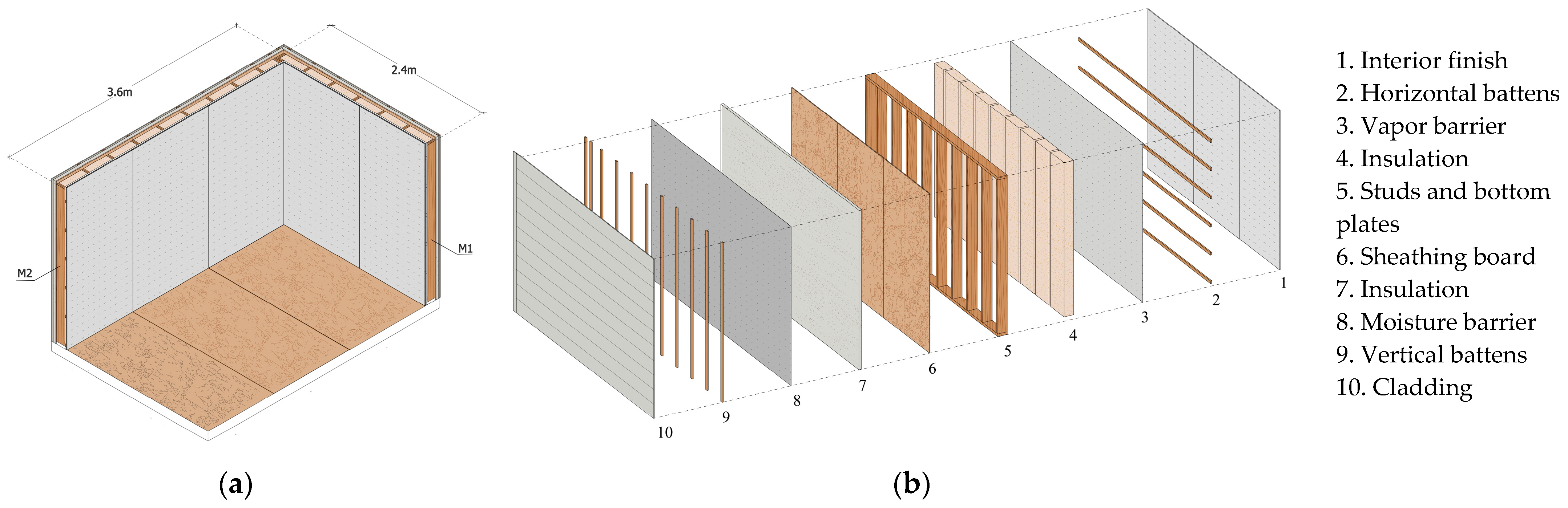
First, a wooden platform measuring 3.66 m × 2.44 m (12 ft × 8 ft) was constructed to fasten two walls positioned at a right angle to each other. The walls are 2.4 m high; M1 is 2.4 m wide and M2 is 3.6 m wide. This setup aims to replicate a typical corner joint in a light wood-frame house, as shown in
Figure 2.
Regarding the execution, all assembly actions were carried out by one qualified person working full-time, with the assistance of an overhead crane for lifting the walls. Additionally, there was occasional collaboration from another worker.
Phases I and II
On the platform, acting as a prefabrication table during the off-site construction process, the assembly of M1 begins by positioning the 38 mm × 140 mm (commercialized as 2 in × 6 in) sawn timber studs with a length of 2.44 m and spaced every 400 mm (16 in) on center. To join the structure, pieces of the same dimension, referred to as bottom and top plates, are placed at the ends and nailed to the studs using a pneumatic nail gun model Metabo HPT. To brace the structure, OSB (Oriented Strand Board) of 11.1 mm in thickness is nailed with the same nail gun, as detailed in
Table 2.
Once M1 is horizontally configured, simulating conditions during the off-site construction process, supports are screwed into the exterior side studs to attach the straps that will lift the wall with the overhead crane. Once secured, it is lifted and positioned onto the platform, and finally, it is nailed from the bottom plate to the edge beams of the platform. After this action is completed, temporary diagonal elements are placed to ensure its verticality in its final location. With the first wall in place, the same process of prefabrication, lifting, and fastening is repeated for M2.
Following the connection of M1 and M2, “Phase II” begins. This stage involves installing the remaining construction components that complement the main structure and form the complete envelope. Unlike Phase I, this is carried out with the panels upright on the platform, working as a complete unit rather than individual elements, simulating on-site construction work.
The process starts from the interior on the platform, installing fiberglass insulation between the studs, held in place exclusively by compression between the studs. Then, over them, the vapor barrier is installed, attached to the structure with staples randomly placed on the studs. Over the membrane, horizontally arranged strapping spaced approximately every 400 mm is nailed. These strappings function as support for screwing the gypsum board panels. Once the boards are fixed, the joints are finished with joint tape and the screw heads are covered with joint compound, leaving everything ready for the final finish, which was not carried out in this experiment.
Lastly, on the exterior side of the corner joint and from outside the platform, rigid insulation boards were installed over the OSB boards, anchored with four nails. Over the polystyrene, the moisture barrier was stapled, and over it, vertical strapping was nailed 16 inches apart, intended to serve as support for the vinyl siding, which was nailed with at least 8 nails per horizontal strip.
2.2. Disassembly
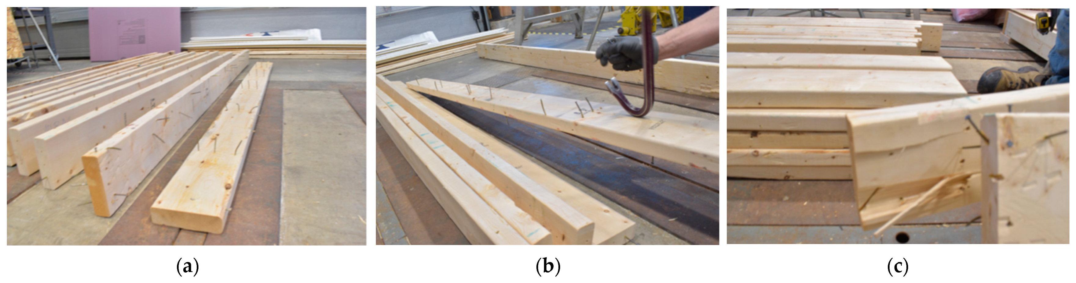
A meticulous disassembly was carried out with a view to future reuse, following a procedure that does not exactly correspond to current practices, which typically involve traditional demolition methods where the integrity of recovered materials is not necessarily preserved. This approach, focusing on efficiently recovering the maximum number of components in terms of time, was divided into two phases: Phase III, which simulated the reverse steps of Phase II on-site, and Phase IV, which achieved the same in relation to Phase I, off-site.
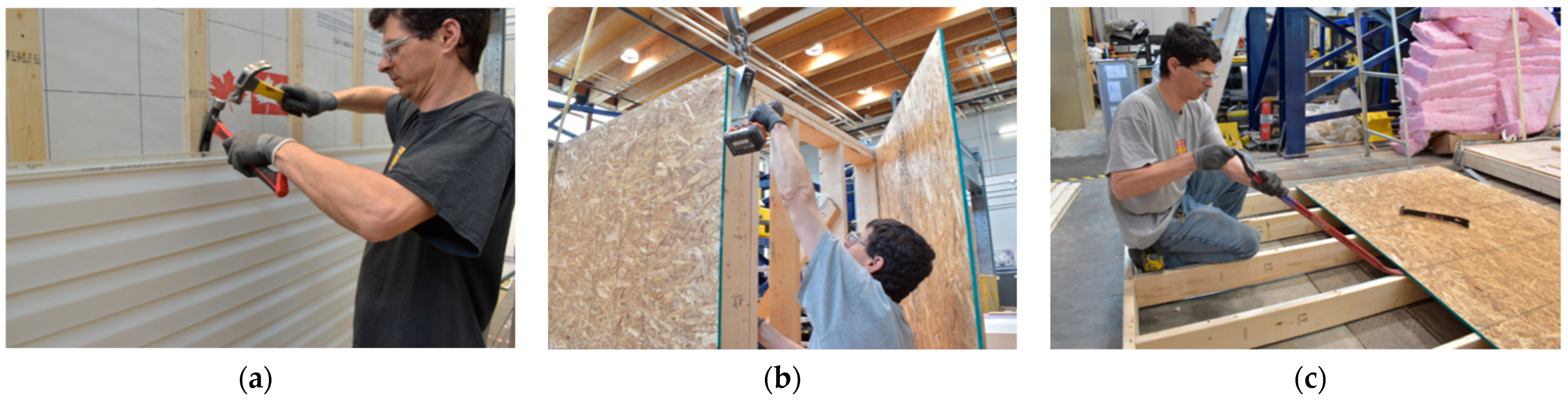
Each step was executed with the same human workload as shown
Figure 3, using the overhead crane to detach the walls from the platform and place them horizontally, as well as hand tools such as hammers and pry bars to decouple the components that were fixed together.
Phases III and IV
Beginning with the top edge siding sheet of the M2 and using the hammer claw, each nail securing the vinyl siding was extracted. The last piece to be removed was the bottom one of M1, which secured the rest of the siding. Once all the vinyl was removed, the vertical battens were pried off with a crowbar, facilitating their careful removal to avoid damaging the underlying insulation. After disassembling all the wooden elements, the moisture barrier membrane was removed without using any tools, leaving the staples embedded in the polystyrene layer. The final step from the exterior was to disassemble the rigid insulation boards, using a crowbar to remove the nails that secured them to the OSB.
The process began from the interior and on the platform by removing the joint covers from the edges of the gypsum board panels and then unscrewing them. Next, the horizontal strapping nailed to the structure was removed, following the same technique used to remove the exterior strapping. The polyethylene was then uninstalled in the same manner as the moisture barrier, revealing the studs and insulation, and finally, the mineral wool was extracted. This action concludes Phase III, reflecting the process performed on-site.
Only the structure of both walls remained standing. Afterward, the lateral supports were installed to hook the overhead crane straps to M2. Using a crowbar, the bottom plate that was nailed to the platform was detached. This step was essential to facilitate the lifting, and with mechanical assistance, the wall was slightly raised to place it on the platform and begin the horizontal disassembly process. The OSB was removed first, followed by the studs and plates, using the same crowbar. The exact same process was replicated with the M1 wall. This phase concludes with the platform being free and horizontal, just as it was at step C1.
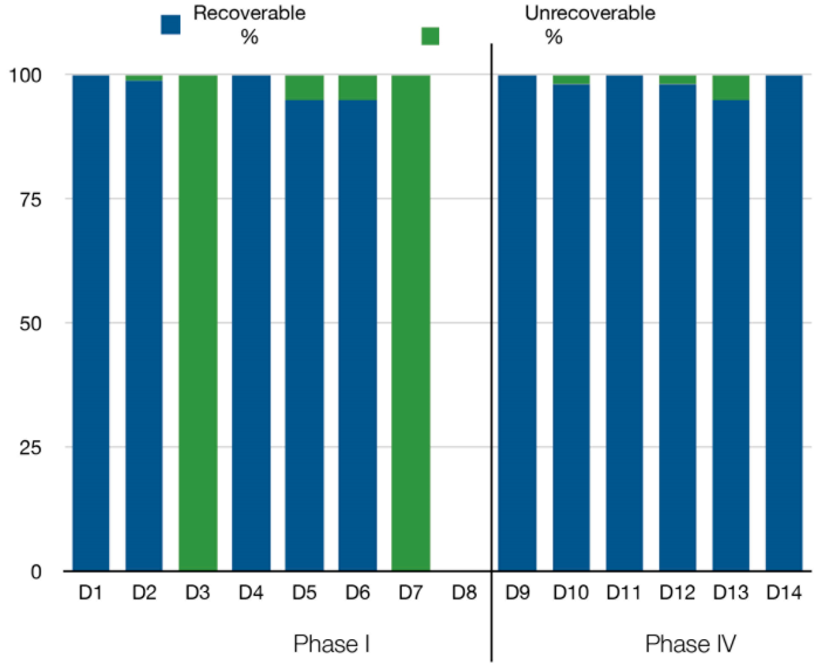
2.3. Parameters to Measure
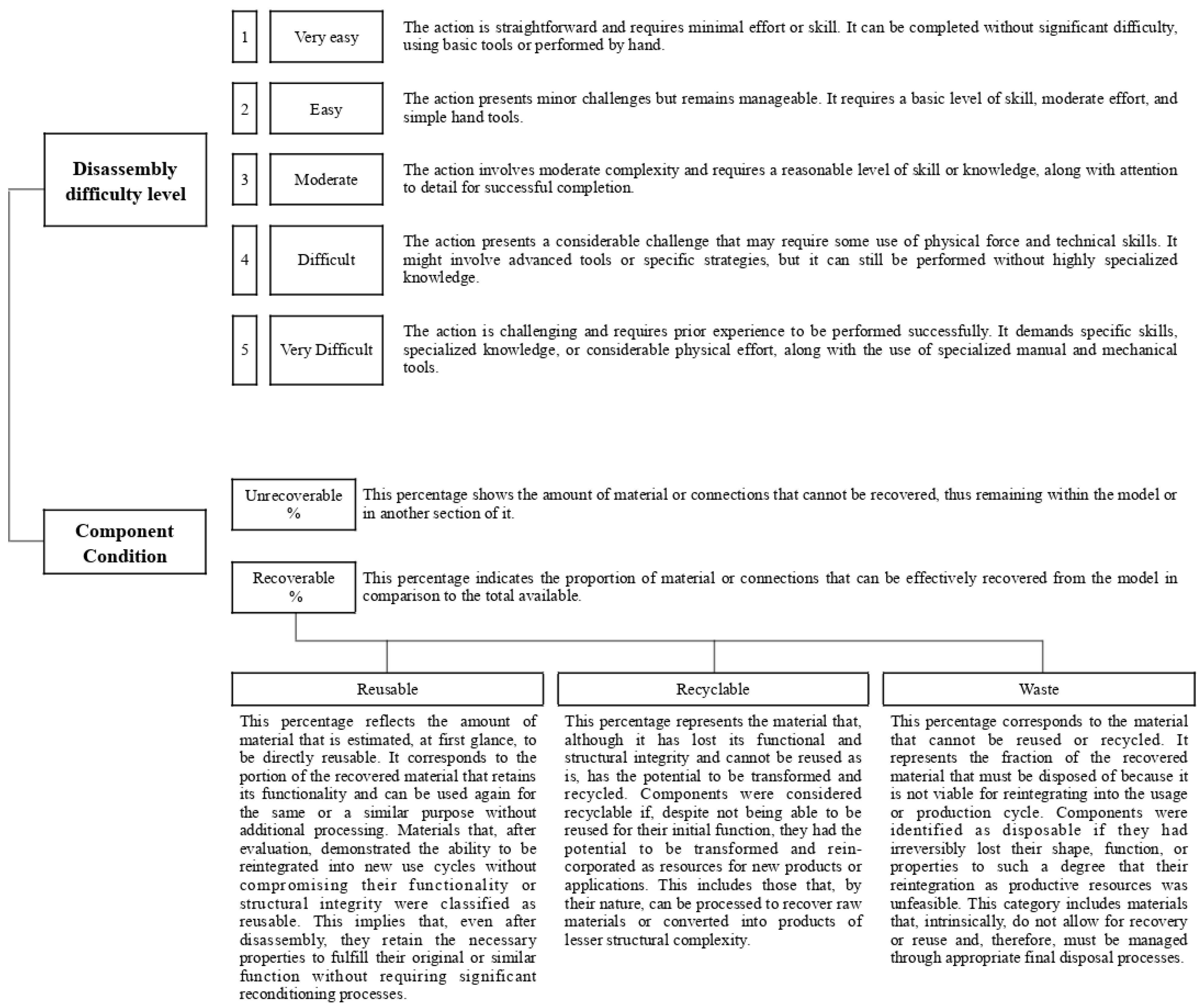
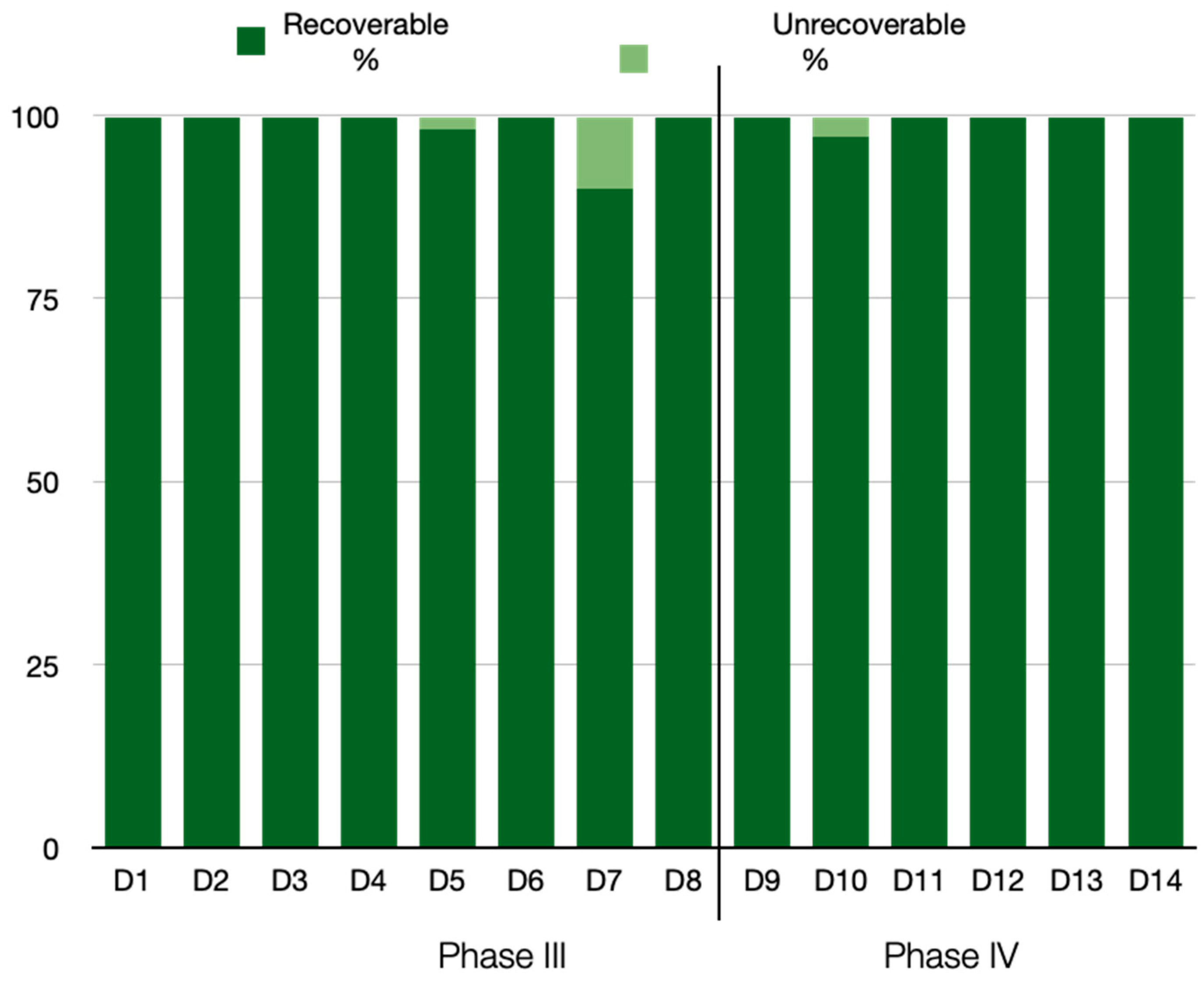
For each action in the disassembly process, three main aspects were evaluated: the level of difficulty, the percentage of material recovered, and its classification as reusable, recyclable, or waste, following the criteria described in
Figure 4.
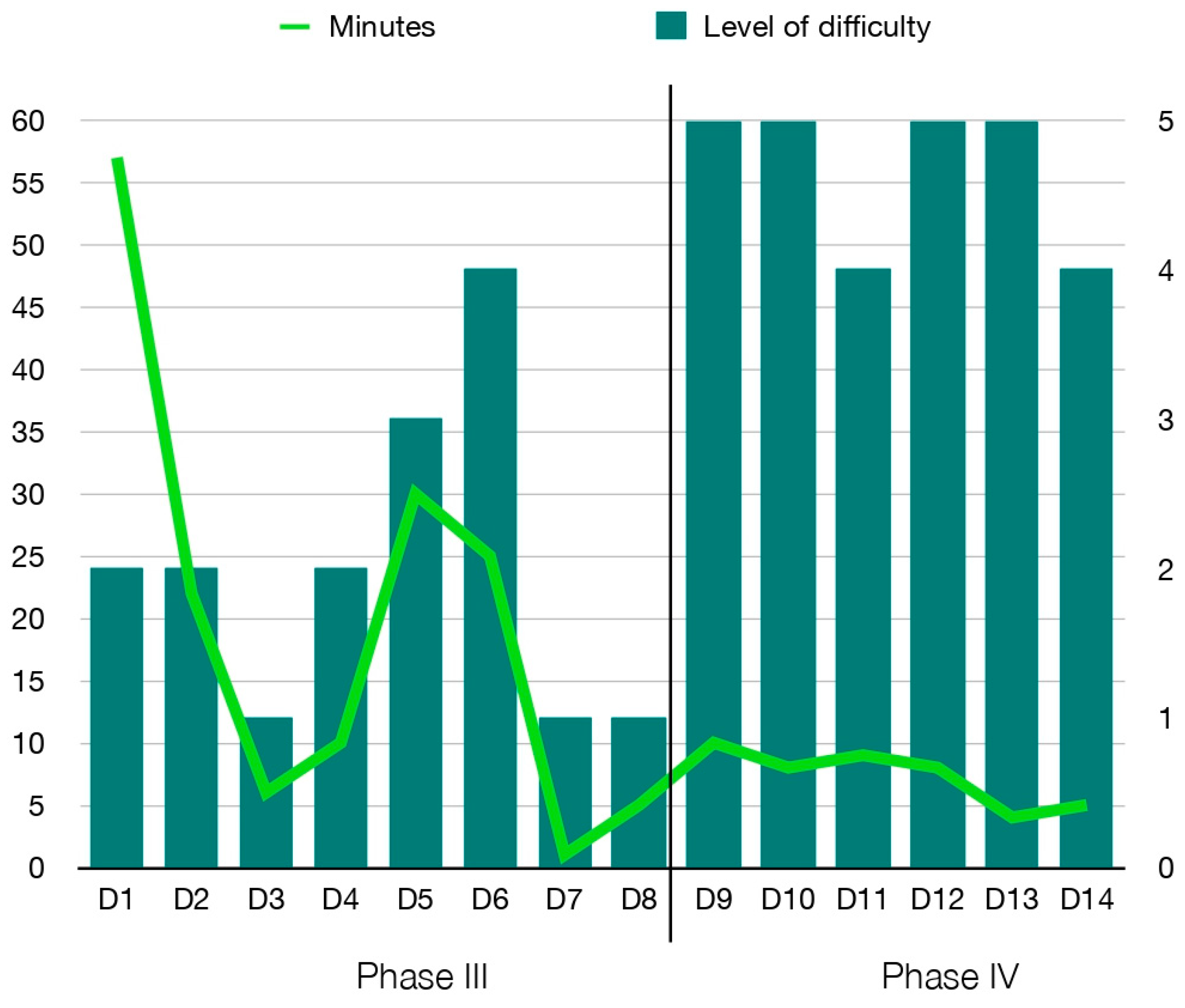
The level of difficulty was assessed using an ordinal scale that categorized actions from the simplest to the most complex, considering both their intensity and the skill required. The worker responsible for the disassembly, with experience in wood construction and lightweight structures, determined the difficulty level of each action based on the descriptors defined in the scale. Complementary to the level of difficulty, the time spent on each action was recorded using a stopwatch, treating it as an independent variable that remains relevant for future comparative analyses.
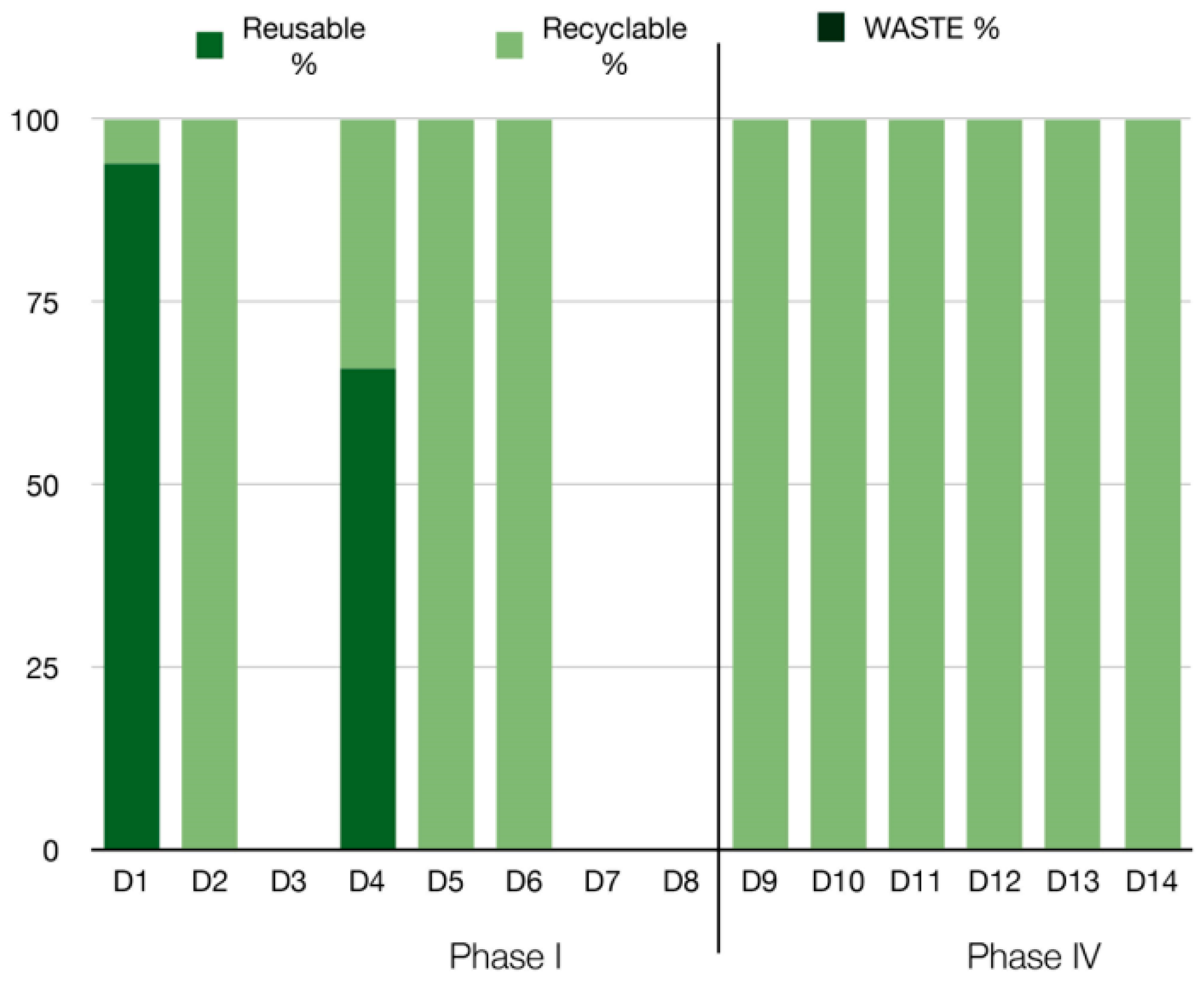
Regarding the recovery of materials and connections, the percentage was recorded for each step performed. The total amount of material involved in a specific action was considered 100%, and based on this reference, the amount recovered after disassembly was measured. For instance, if 100 nails were used to secure the panels and 90 were successfully recovered, a recovery rate of 90% was established. This recovered percentage was then redefined as 100% within the context of classification, allowing for differentiation of the proportions of material that were reusable, recyclable, or waste.
2.4. Analysis of the State of the Components
Once the components and connections were recovered, their condition was evaluated to classify them according to their final state as reusable, recyclable, or waste. This process involved a detailed inspection of each element to identify potential damage or wear, distinguishing between those originating during the construction phases and those caused during the disassembly phases. The classification was based on observations made in a laboratory environment, using evaluation criteria with clear and detailed descriptors (semantic anchors), as specified in
Figure 4. These descriptors uniformly defined the requirements of each category, ensuring consistency in the interpretation of the results.
The definitions used for the subsequent classification of materials and connections were established based on these criteria, omitting external variables that affect actual operational conditions, such as climatic fluctuations, the passage of time, and mechanical or physical wear, among others.
4. Discussion
The analysis of the full-scale model revealed challenges in the disassembly process, largely attributable to the absence of specific Design for X methodologies aimed at optimizing the recovery and reuse of components. The conventional construction system, focused on maximizing speed and efficiency during assembly, did not include strategies for efficient disassembly, resulting in inevitable material degradation and low reuse rates. Additionally, the products used in the model were not ideal for facilitating efficient disassembly or maximizing their subsequent use.
In this context, materials were not selected with reuse or recycling criteria, significantly limiting their reintegration into a new cycle. This highlights the importance of reevaluating construction systems to better align them with circularity principles. In cases where the reuse potential of materials is limited, their recyclability becomes critically important. It is essential to distinguish between materials that can be efficiently recycled and those that, while technically recyclable, present significant challenges, such as nails, whose extraction process from timber is considerably time-consuming, complicating their practical application in large-scale projects. Therefore, when specifying materials, it is important to consider not only their functional properties but also their recyclability, to minimize waste generation at the end of a building’s life cycle.
These findings align with what Passarelli [
40] and Rakhshan et al. [
15] have pointed out: many buildings are not designed with disassembly criteria in consideration, which limits the possibility of efficiently recovering structural components. Studies such as that by Minunno et al. [
41] highlight that integrating disassembly from the initial design phases allows for component recovery without compromising structural integrity. In this case, the analysis of the corner joint of two lightweight timber panels showed that the lack of a Design for Disassembly significantly reduces the potential for material reuse.
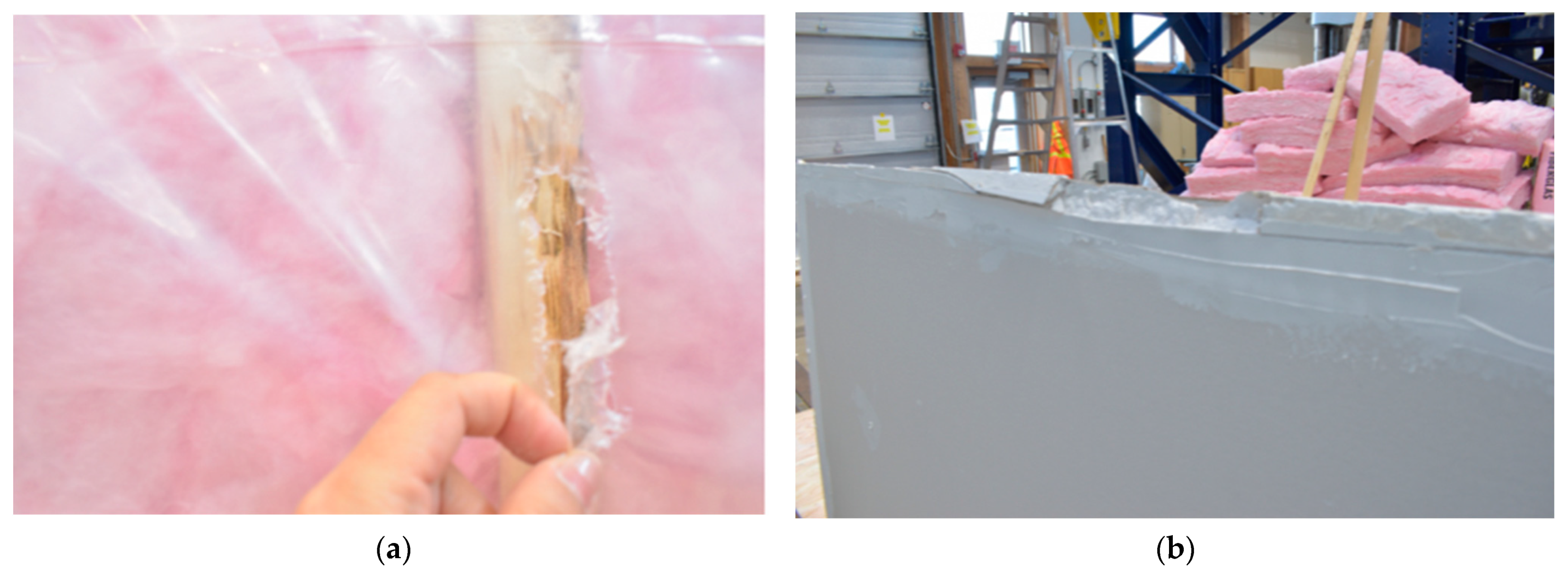
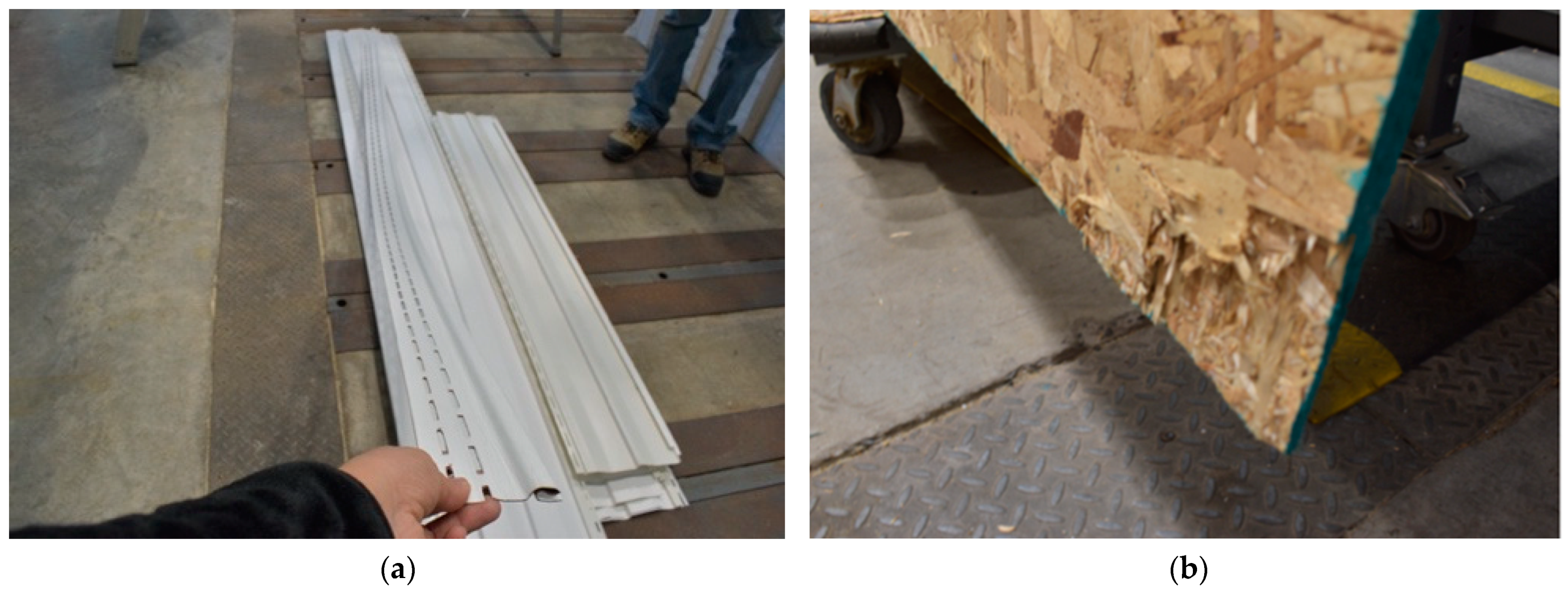
One of the primary barriers observed in the model was the use of pneumatic nails, a type of non-reversible fastener, which, by piercing multiple layers of the panel, caused significant alterations. These alterations compromised the possibility of reusing certain products, like the vapor barrier, by causing tears on its surface. This finding is consistent with Finch et al. [
7], who noted that fasteners penetrating multiple layers tend to compromise material integrity during disassembly.
Unlike nails, other mechanical fasteners, such as screws, bolts, or anchoring systems, would allow for more efficient layer separation as they do not damage the materials during disassembly [
3]. Although glued joints, such as adhesives, were not applied in the evaluated model, they are known to hinder disassembly and reuse, often requiring destructive processes to separate materials [
3]. In fact, Machado et al. [
25] points out that using mechanical fasteners instead of glued ones facilitates component separation without excessive force, reducing contamination and minimizing damage to materials. However, as observed in the studied model, nails, despite being a mechanical fastener, do not meet these conditions, as removing them exerts considerable pressure, causing tears and damage to adjacent materials, compromising their eventual reuse.
Authors believe that using reversible intra-panel fasteners is essential to improve material disassembly within a single panel. This approach aligns with one of the key principles of Design for Disassembly (DfD), which is to ensure layer independence. Allowing for controlled layer separation minimizes damage. Since each layer has different levels of resistance and wear, it is crucial to consider their durability from the design stage. By rethinking the fastening system, not only is disassembly optimized, but materials with shorter lifespans can also be efficiently replaced without compromising the structure or increasing maintenance or replacement costs.
Similarly, inter-panel fasteners, which are currently resolved also with nails, require implementing reversible fasteners to facilitate efficient disassembly between panels. In lightweight panelized timber framing systems, reversible plug-and-play connections are essential for implementing DfD principles in prefabrication, as Yan et al. [
42] noted. However, these connections have been mostly applied in solid timber systems and not in lightweight framing, and their disassembly feasibility has not been fully evaluated. Their limited use is mainly due to the high costs of specialized fasteners, while lightweight construction in countries like Canada still relies on nails, which, while reducing costs and speeding up assembly, prevent efficient disassembly without causing significant damage. In this context, any disassembly attempt becomes practically unfeasible without compromising material integrity.
Another crucial aspect related to material integrity is the preservation of their original dimensions. In the model, it was observed that damaged materials, especially at their corners, lose this capacity, compromising their reuse. Although resizing is an option, it affects dimensional standardization, a key factor in ensuring compatibility between different construction systems and facilitating both disassembly and material reuse [
29]. This is particularly relevant in markets like Canada for light timber frame systems, where standardization is essential to ensure the reintegration of materials into new construction processes.
Regarding prefabricated lightweight timber panel systems, it is essential to adopt an integrated approach between Design for Disassembly and Design for Manufacture and Assembly (DfMA), as suggested by Roxas et al. [
27]. Although both approaches have been addressed individually, few studies integrate them, especially in lightweight framing systems. This study contributes to understanding this relationship, demonstrating that combining these methodologies not only has the potential to optimize disassembly and streamline construction processes but also promotes the development of more circular industrialized systems. In line with this, Tavares et al. [
31] agree that industrialized prefabrication, together with modularization, material standardization, and the use of dry connections, facilitates both disassembly and the efficient recovery of components for reuse. Thus, the joint implementation of these strategies allows for maximizing material use throughout its life cycle, thereby reducing construction and demolition waste generation.
There is a consensus regarding the long-term economic and environmental benefits of Design for Disassembly, although it faces technical, economic, and logistical barriers, such as the lack of demand and the absence of adequate processes [
43]. For example, ref. [
29] highlights that there is currently no clear standard defining which components or connection systems should be standardized, despite the general principles of ISO 20887. Although this standard emphasizes the importance of designing buildings that incorporate traceability and planning for component reuse, its guidelines are still too general and challenging to apply in practice, limiting its effectiveness in structural projects.
In the context of the circular economy, one of the main challenges is the lack of regulations and standards that address the state and condition of reusable materials. This absence of specific standards hinders the proper valuation of components at the end of their life cycle, complicating their integration into new production cycles. Additionally, it is essential to develop databases that comprehensively record information on buildings, including modifications and renovations throughout their life cycle. These tools would enable more precise planning for component recovery, promoting more sustainable practices, and facilitating the effective reintegration of materials into future construction processes [
15].
4.1. Disassembly
The disassembly process carried out on the model revealed that task duration is not directly linked to its complexity, highlighting the need to optimize both fasteners and materials used. This optimization would not only improve disassembly efficiency but also minimize material deterioration, preserving their integrity for future reuse. Lacovidou and Purnell [
17] emphasize that although precise techniques such as nail removal better preserve timber elements, they also increase the time required for their recovery.
In large-scale projects, proper planning and logistics are crucial to reduce the time and costs associated with disassembly. While deconstruction offers clear environmental benefits, its main challenge remains time, which can be up to 29% longer than demolition [
35]. This longer duration creates a preference for demolition, especially when costs and timelines are determining factors [
29].
Another key aspect for disassembly efficiency, observed in the experiment, is the level of prefabrication. In the studied model, the low prefabrication level, focused only on the structure, required elements such as insulation and finishes to be dismantled on-site, increasing the time and effort needed. A higher degree of prefabrication, integrating these elements in the factory, would allow complete panels to be transported for refurbishment, maximizing material reuse and improving both time efficiency and resource use.
4.2. Study Limitations and Future Directions
Among the limitations of this study is the fact that the evaluation of difficulty levels was conducted by a single worker. Although a qualitative scale was defined and efforts were made to minimize subjectivity by selecting an individual with experience in timber construction and the disassembly of light-frame timber houses, the results reflect the personal perception of the effort required. To reduce this subjectivity, future experiments should involve multiple workers, either independently to average their results or collaboratively to compare their perceptions.
Similarly, the classification of materials as reusable, recyclable, or disposable relied on qualitative criteria and direct observation of the recovered materials. While this approach is practical, it is influenced by subjective judgment, local recycling capacities, and the regulatory frameworks of each country, particularly for materials that cannot be reused.
Focusing the disassembly evaluation on a fragmented model limits the understanding of the complexities inherent in a full-scale building, such as the integration of electrical, plumbing, and heating and ventilation systems, which significantly affect the disassembly process and the potential for material reuse. Additionally, the lack of a comparative analysis involving different mechanical or chemical fasteners further restricts the scope of the conclusions.
To address these limitations, it is crucial to evaluate the performance of various fasteners within these systems to identify those that optimize both assembly and disassembly processes. Moreover, incorporating electrical and plumbing systems in larger-scale studies would provide a clearer understanding of their impact on panel disassembly. The development of panelized housing prototypes that integrate the principles of DfD (Design for Disassembly) and DfMA (Design for Manufacturing and Assembly) from the early design stages would offer a comprehensive assessment of the benefits of these approaches in real-world construction scenarios, contributing to a more circular construction industry. Designing solutions that account for disassembly from the initial stages of the project is essential to ensure efficient component reuse and to minimize waste generation.
Finally, it should be noted that the findings of this study need to be validated with a larger sample size, as the current analysis is based solely on a single scaled model.


