1. Introduction
With the rapid progress of urban economy, the development and utilization of underground space keep increasing, and the depth of foundation pit projects is constantly increasing [
1,
2,
3,
4,
5,
6,
7,
8]. Due to the shortage of land on the project site, terrain restrictions, and other reasons, it is often necessary to stack machinery and materials on the side of foundation pit during excavation, causing the problem of eccentric loads in foundation pits, which has been thoroughly investigated using theoretical analysis, numerical simulations, and field tests [
9,
10,
11].
In terms of theoretical analysis, Moormann et al. [
12] analyzed the main factors affecting the foundation pit based on over 530 foundation pits, pointing out that the maximum horizontal displacement zone was approximately twice the excavation depth of foundation pit. Fan et al. [
9] systematically investigated how unequal pile lengths, pile stiffness, and bracing stiffness affect pile lateral displacement, bending moment, and earth pressure under asymmetric excavation, and proposed a design concept for asymmetric optimization of pile length.
In terms of numerical simulation, many researchers have reached similar conclusions [
13,
14,
15,
16,
17,
18,
19,
20]. Specifically, the horizontal displacement and bending moment of support on both sides of foundation pit are significantly different under different eccentric loads. In excavation projects subjected to eccentric surcharge loading, the retaining system tends to deform as an integrated whole toward the non-surcharge side, rather than exhibiting the conventional symmetric deformation pattern. The maximum bending moment of loaded side pile increases with the increase in load, while the maximum bending moment of non-loaded side pile decreases.
In addition, a large number of field measurement studies have been conducted [
21,
22,
23,
24,
25,
26,
27,
28,
29]. Through field tests on an actual foundation pit, Huang [
30] found that the mountain eccentric load had a stronger influence on the foundation pit than the river eccentric load; the horizontal displacement of the diaphragm wall mainly exhibited a “convex belly” shape, and the subsidence curve tended to have a “spoon” shape; the maximum horizontal displacement of enclosure wall was positively correlated with the excavation depth. Zhang et al. [
31] analyzed how thickening the wall on the unloading side or installing protective piles influences the deformation and internal force response of the wall on the biased-load side, and, on this basis, further examined the sensitivity of support performance to the embedment depth of supporting piles and the thickness of the diaphragm wall.
Although numerous numerical simulations and field measurements have investigated the mechanical behavior and deformation characteristics of excavations under eccentric loading conditions, systematic physical model tests remain relatively scarce, making it difficult to fully elucidate the formation and evolution mechanisms of asymmetric failure. Meanwhile, effective control and optimization measures for mitigating the non-uniform deformation of retaining structures induced by eccentric loads still lack systematic and quantitative research. To address these gaps, this study integrates physical model tests with validated three-dimensional numerical analyses to comprehensively reveal the deformation mechanisms of retaining structures under eccentric loading. Furthermore, optimization strategies and practical design guidelines are developed for key parameters such as wall thickness and embedment depth. The outcomes of this study not only enrich the understanding of excavation deformation responses under eccentric loading but also provide significant engineering guidance for displacement control and structural optimization in deep excavations subjected to asymmetric loads.
2. Foundation Pit Modelling Test Under Eccentric Load
2.1. Physical Model Materials
2.1.1. Model Box Configuration
Physical model testing offers strong controllability and low cost, and the responses measured on the scaled model can reliably represent the stress and deformation of the prototype. It therefore provides a practical, visually informative, and systematic approach. In this study the geometric similarity ratio is set to 1 to 10. Geometric dimension, density, and gravitational acceleration are selected as the fundamental dimensions. Based on the second similarity theorem, the similitude criteria are derived and dimensional conversions are performed, yielding the similarity relations and constants for all variables. The results are reported in
Table 1.
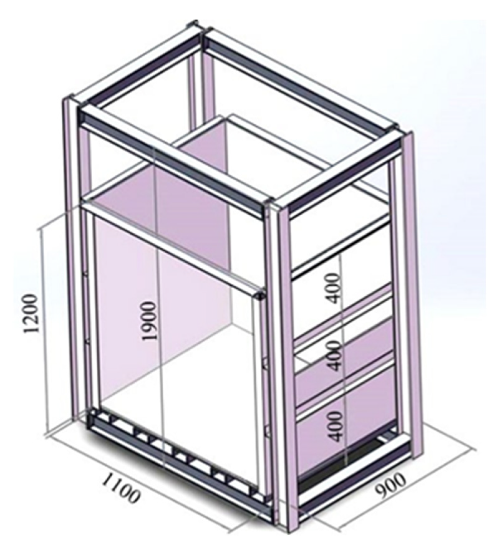
Figure 1 illustrates a schematic of the model box used in this study. The size of the model box is 1.1 m (length) × 1.2 m (height) × 0.9 m (width). The front side is made up of 18 mm-thick reinforced glass (used for monitoring soil displacement), and the other three sides are 10 mm-thick plates.
2.1.2. Soil Samples
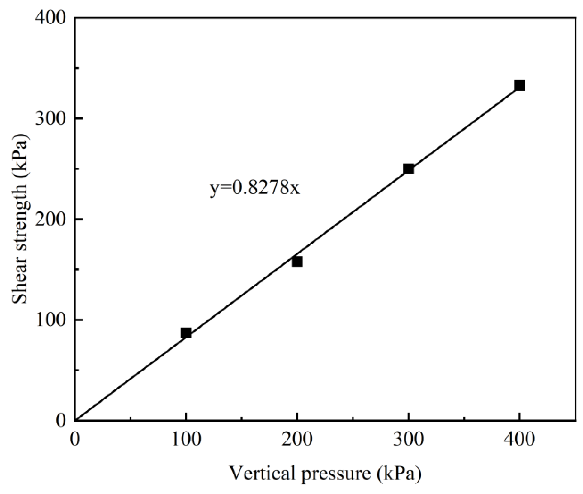
Standard sand was used in the modelling test. The basic physical and mechanical properties were obtained from particle grading test and direct shear test. In the direct shear test, the variation in shear strength with vertical pressure is shown in
Figure 2. The final results of basic physical and mechanical properties are shown in
Table 2.
2.1.3. Supporting Structure Materials
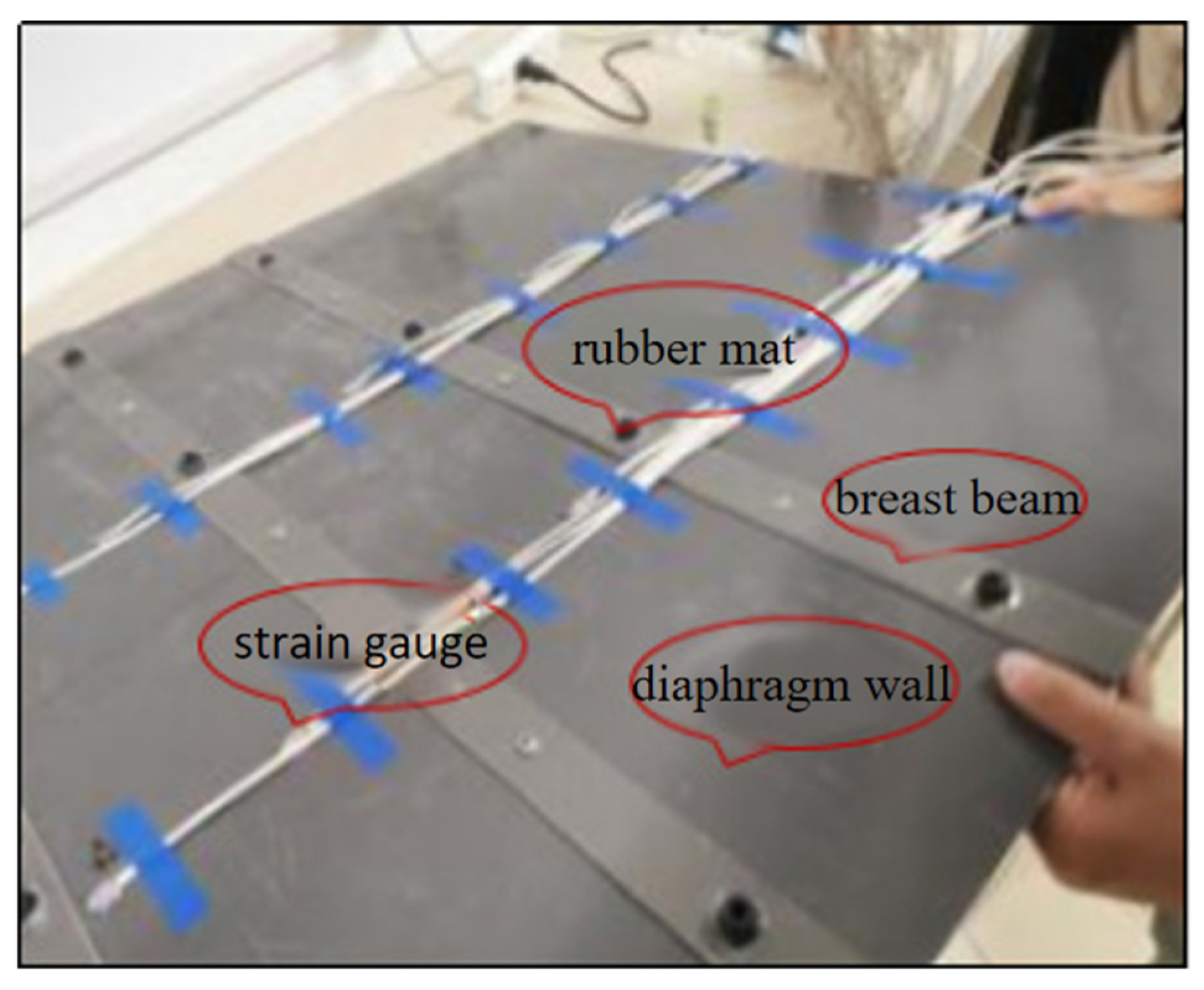
Given the manoeuvrability and good deformation property of the material, a trial test was conducted in advance (
Figure 3). PVC pipes with a diameter of 20 mm, thickness of 2 mm, and the elastic modulus of 3.44 × 10
9 Pa were used. A 5 mm-thick PVC plate was used to model the enclosure (
Figure 4), and tensile tests were performed to measure its elastic modulus, which was found to be 3.44 × 10
9 Pa.
2.1.4. Structural Installation Description
The support frame was pre-assembled and positioned prior to excavation. To ensure positional stability, the member ends were lightly pressed into the prepared sand using a static jig, without impact driving or preloading. The intent was to secure alignment while minimizing boundary disturbance and maintaining realistic wall–soil interaction.
2.2. Displacement Measurement Layout of the Test Model
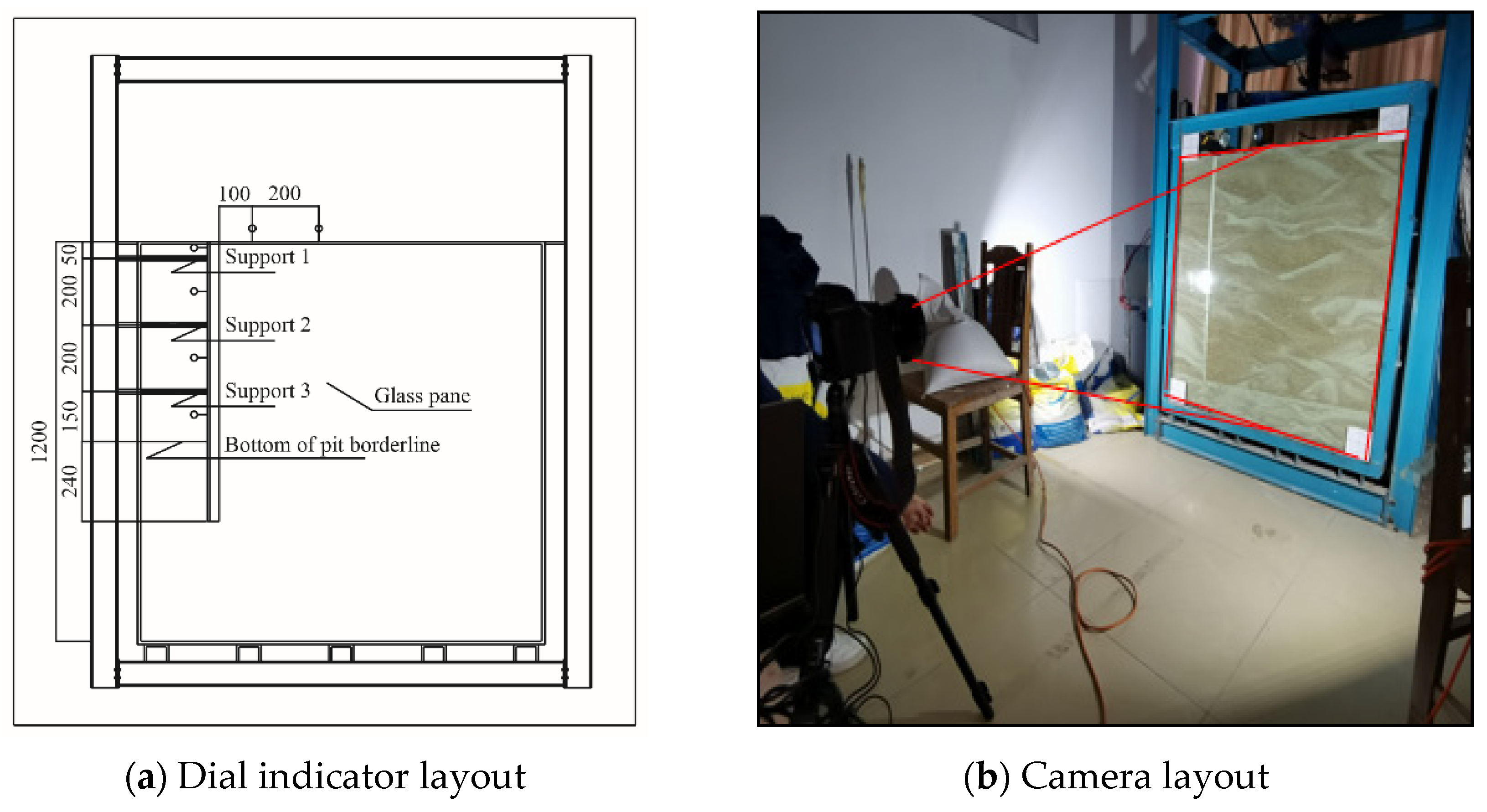
The displacement was obtained through two different measurements. The first one was the measurement of soil deformation in the middle of the enclosure and around the pit with a dial indicator. The second was to set up a particle image velocimetry (PIV) camera to measure the soil displacement under different working conditions through reinforced glass and generate displacement cloud maps using the photo information. The dial indicator and camera arrangement are shown in
Figure 5.
2.3. Working Conditions
Despite rigorous efforts to minimize experimental artifacts, it is recognized that physical modeling inherently involves scale effects and boundary constraints, which may influence the quantitative accuracy of the results, a limitation widely acknowledged in physical model studies. During the excavation stage, no active support was applied in accordance with the principle of the “total load method,” which aims to reproduce the final mechanical state of each working condition while avoiding disturbances associated with intermediate loading steps, thereby ensuring the integrity of stress redistribution within the model. After the completion of excavation, a constant vertical surcharge was imposed on one side of the excavation. The load was applied using a vertical actuator equipped with a rigid loading plate at its end, which transformed the actuator’s concentrated force into a uniformly distributed surface load over the designated area. The applied load was precisely regulated by a computer-controlled system that maintained constant loading conditions through real time feedback throughout the test. The specific working conditions of excavation and loading for the modeling tests are listed in
Table 3.
2.4. Enclosure Displacement
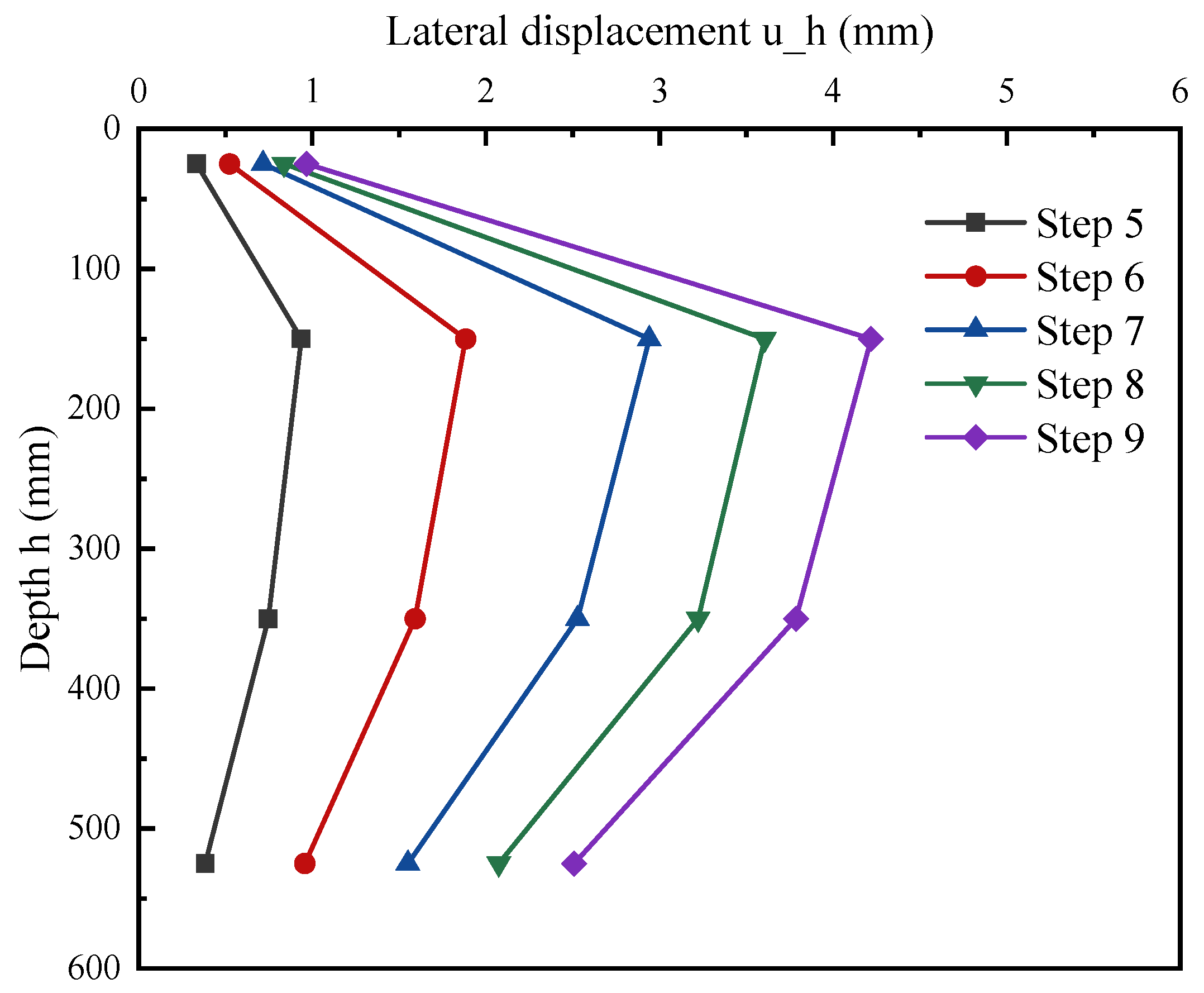
Figure 6 demonstrates the horizontal displacement of the enclosure at different positions and its deep horizontal displacements under loads measured by the dial indicator, respectively.
As shown in
Figure 6, due to the limiting effect of the first internal support at the top on the enclosure deformation, the maximum horizontal displacement occurs near the second support. The overall deep horizontal displacement of the enclosure under loads first increases and then decreases with the excavation, which is similar to the deformation trend in the field test, verifying the accuracy of the lab modelling test. As the load on the top increases, the maximum deformation of the enclosure grows from 1 mm at 10 kPa (working condition 5) to 4.3 mm at 50 kPa (working condition 9). Further indicating the significant effect of load on the enclosure deformation.
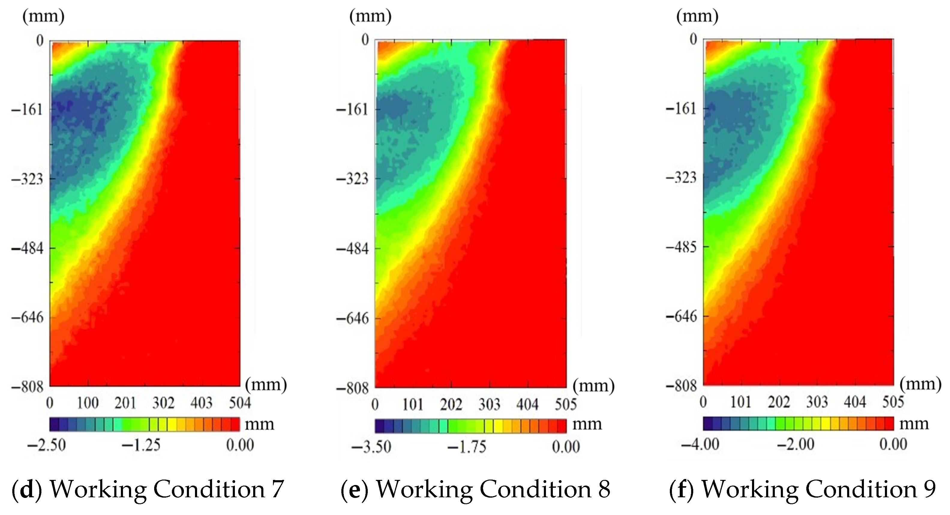
The overall displacement of support under excavation and loading was investigated. The clouds of horizontal displacement under excavation and loading are shown in
Figure 7.
At an excavation depth of 600 mm, the maximum lateral displacement occurs at approximately 200 mm below the ground surface. With increasing surcharge, the potential slip surface becomes clearer and propagates upward at 60° from the base. Near the second support (200 mm depth), the retaining wall exhibits opposite-direction lateral movements on the loaded and unloaded sides, consistent with the observed asymmetric earth-pressure redistribution.
Under eccentric surcharge, the soil mass on the loaded side experiences elevated shear stress and tends toward active conditions, forming an outward-moving wedge that drives the diaphragm wall. The induced lateral thrust is transferred through the wall and internal supports, causing the unloaded side to experience passive reaction and surface uplift away from the excavation face. As the surcharge increases, particle rearrangement and localized plasticity concentrate near the wall–soil interface on the loaded side, while the rotation point of the wall migrates downward, shifting the depth of maximum displacement toward the second support. The emerging slip surface aligns approximately 60° to the base, reflecting the mobilized frictional resistance and the transition from elastic to plastic deformation. Increased wall thickness and embedment depth enhance passive resistance and reduce curvature demand, thereby flattening the displacement profile and suppressing the lateral spreading of the failure zone. Therefore, these observations indicate that toe fixity is the primary lever for mitigating the opposite-direction movements on the two sides. In practice, displacement control should first increase embedment on the loaded side; if the target is still unmet or deepening is constrained, apply moderate wall thickening as a secondary adjustment.
3. Numerical Modelling Test of Foundation Pit Under Eccentric Load
3.1. Numerical Model
To further investigate the influence of asymmetric soil deformation on both sides of a foundation pit induced by localized eccentric loading, a three-dimensional finite element model is developed based on the validated physical model results to generalize the findings and perform parametric studies on wall thickness and embedment depth for effective displacement control under asymmetric loading. By comparing the simulation results with indoor experimental data, the control effectiveness of support structure thickness and embedment depth on pit deformation under eccentric loading is analyzed. The soil in the model is simulated using the Hardening Soil model, which better captures the stress release and transfer in surrounding soils during both excavation and eccentric load application processes. The internal supports are modelled using beam elements, while the retaining piles are modelled using plate elements. Throughout the entire analysis process, the elastic modulus of the supporting structure remains constant and is taken as
. In the Soil Hardening model, stiffness is characterized by three reference parameters: the oedometer modulus for primary loading
, the secant modulus at 50% of failure deviatoric stress from a standard drained triaxial test
, and the unloading/reloading modulus
. In accordance with the PLAXIS Material Models Manual and relevant literature [
32,
33,
34], this study adopts
for dense sand, while the unloading–reloading modulus is taken as three times the oedometer modulus. To more accurately simulate the interaction mechanism between the surrounding soil and retaining structures under eccentric loading, a strength reduction factor
of 0.6 is applied at the interface between the soil and plate elements [
35,
36].
3.2. Comparative Analysis Between Physical Model Tests and Numerical Simulations
A uniform surface load with an intensity ranging from 25 to 150 kPa and a horizontal distribution width of 3 m is applied on the side adjacent to the excavation face to simulate eccentric loading caused by nearby buildings or equipment stacking in real engineering scenarios.
Figure 8 shows the horizontal deformation cloud map of the pit soil after the application of eccentric loading. When the load is applied at the ground surface, the soil on the loaded side undergoes active deformation under high shear stress. The soil in the high-stress concentration area experiences considerable compression and lateral extrusion, leading to rearrangement of soil particles and the formation of a distinct lateral displacement concentration zone at the location of the diaphragm wall on the loaded side.
Consistent with stress distribution characteristics observed in plate-load measurements, the lateral influence of the surcharge attenuates with distance and is transmitted through the wall and internal supports. Consequently, passive deformation occurs on the ground surface of the non-loaded side, moving away from the excavation face, and the soil undergoes elastic deformation. At this stage, the upper soil on the non-loaded side slides downward due to shear failure, increasing the active earth pressure from the lower soil against the retaining structure. The diaphragm wall undergoes lateral deformation due to bearing capacity failure, leading to active deformation of the soil behind the wall.
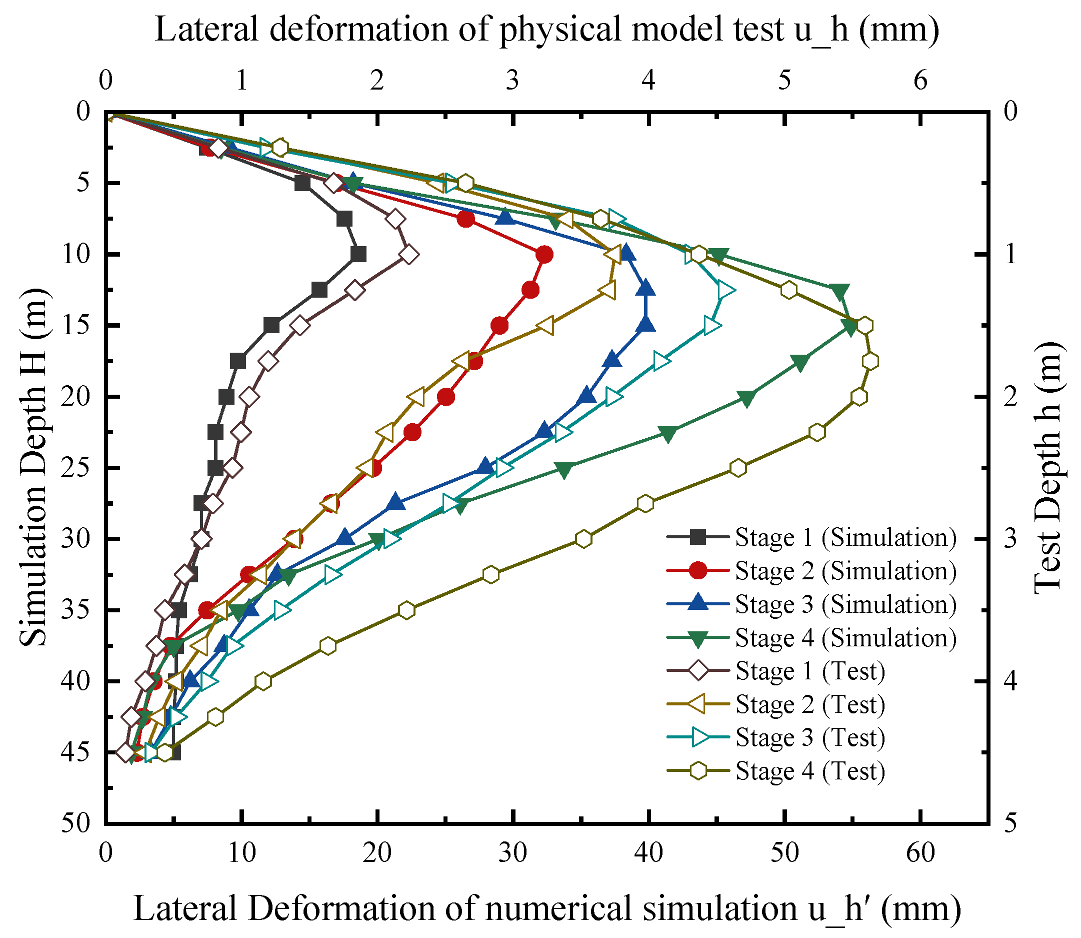
Figure 9 presents a comprehensive comparison of the horizontal displacement profiles of the excavation support structure obtained from both numerical simulations and indoor model tests under incrementally applied lateral bias loads. Overall, a good agreement is observed between the numerical simulation results and the indoor experimental measurements across all loading stages. At lower loading stages (Stage 1 and Stage 2), the numerical predictions closely match the experimental observations, with only minor deviations. This indicates that the numerical model effectively captures the linear or nearly linear elastic response of the soil-support system under smaller loading conditions. Although slight variations were present at elevated loading conditions, the numerical model effectively reproduced the global deformation behavior and the responsiveness of the support system to increased lateral loading. It was observed that the point of maximum deformation within the support structure migrated downwards with escalating loads, a finding entirely consistent with laboratory experimental outcomes. Consequently, the strong agreement between the numerically derived horizontal displacement profiles and the empirical results validates the established numerical model’s robustness and predictive capacity, thereby affirming its suitability for subsequent research on deformation control of foundation pits. Consequently, the strong agreement between the numerically derived horizontal displacement profiles and the empirical results validates the established numerical model’s robustness and predictive capacity, thereby affirming its suitability for subsequent research on deformation control of foundation pits.
4. Discussion
4.1. Effects of Supporting Plate Thickness Adjacent to Load on Soil Deformation Characteristics
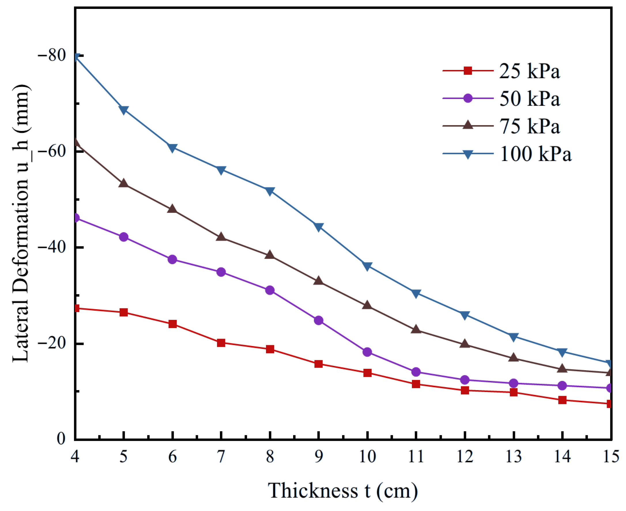
Figure 10 illustrates the variation in excavation horizontal displacement with retaining wall thickness under different levels of asymmetric loading. Overall, the curves indicate a pronounced negative correlation between wall thickness and displacement, with a nonlinear decreasing trend as thickness increases. Taking the maximum load of 100 kPa as an example, when the wall thickness is only 4 cm, the lateral displacement reaches approximately −80 mm, suggesting insufficient excavation stiffness and significant horizontal movement of the retaining structure under high loading. As the thickness increases to 10 cm, the displacement is reduced to about −40 mm, nearly a 50% decrease. Beyond 12 cm, however, the rate of reduction diminishes, implying diminishing marginal benefits of further thickening.
Moreover, the numerical results in
Figure 10 demonstrate that under high asymmetric loading, enhancing wall stiffness through increased thickness plays a critical role in maintaining excavation stability and suppressing excessive deformation. This is because greater loads impose more complex stress states on the soil, making significant plastic deformation and displacement more likely. In such cases, retaining structures with higher flexural stiffness can more effectively resist and redistribute earth pressure, thereby controlling deformation within acceptable limits. Mechanistically, thickening increases wall stiffness and reduces curvature demand, which explains the pronounced displacement drop at lower thickness ranges and the subsequent marginal effect.
4.2. Effects of Supporting Plate Depth Adjacent to Load on Soil Deformation Characteristics
As shown in
Figure 11, under varying asymmetric loading conditions, a deeper embedment depth of the retaining wall on the loaded side significantly enhances the passive earth resistance at the lower portion of the structure, thereby increasing the effective support length and improving the overall overturning stability and deformation stiffness of the retaining system. The deeply embedded portion of the wall more effectively restrains the plastic flow of the soil, converting the horizontal thrust generated by the upper soil into shear stress along the depth and transferring it to deeper, more stable soil layers.
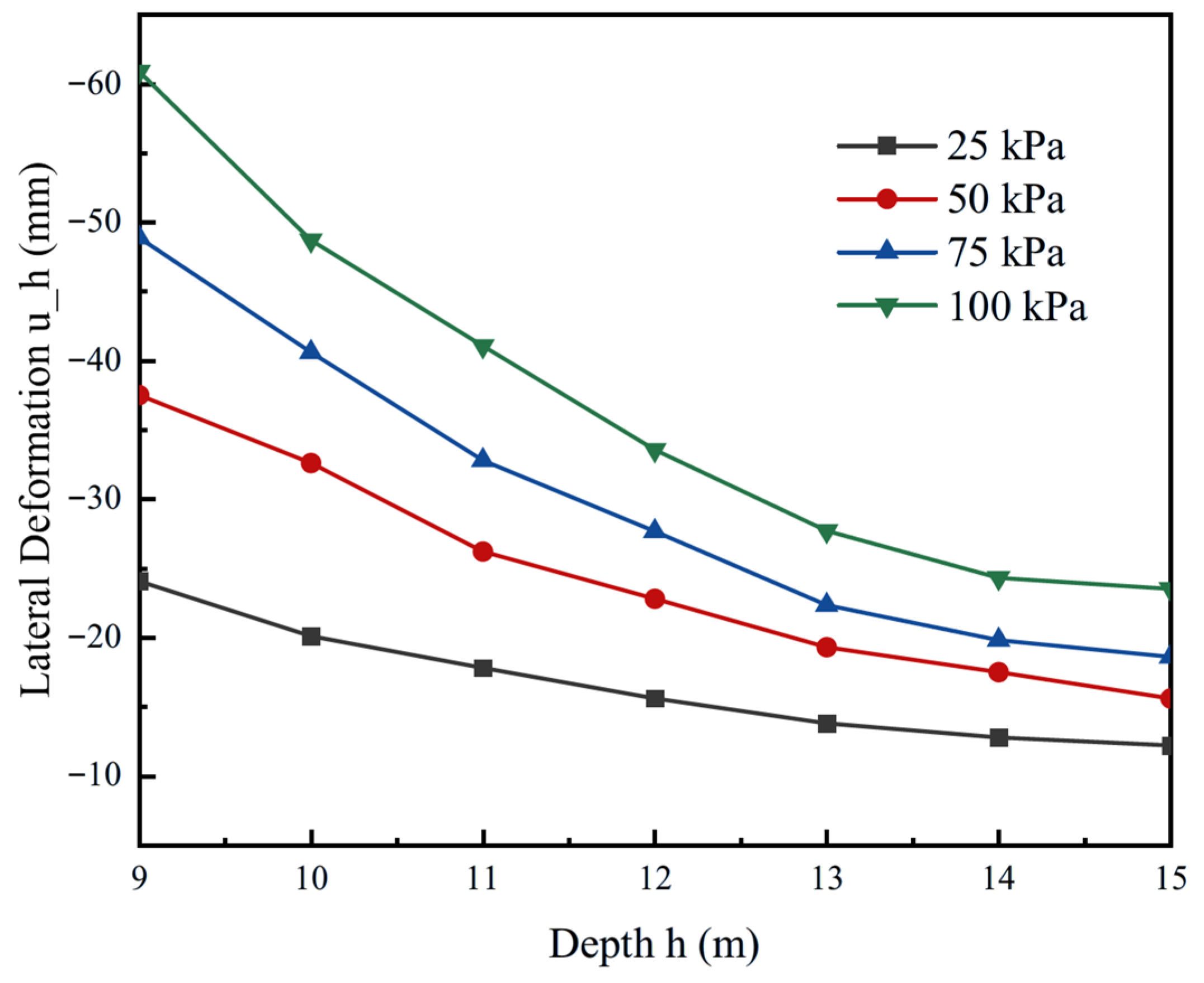
When the retaining wall length is 12 m (2 times the excavation depth), the maximum horizontal displacement of the excavation is reduced by nearly 50%. However, it is noteworthy that the effect of embedment depth on displacement control is not linearly increasing; after reaching a certain depth, the marginal benefits begin to diminish. As observed in the figure, when the embedment depth exceeds twice the excavation depth, the slope of the load-displacement curves noticeably decreases and tends to flatten. Therefore, in the engineering application of excavations under asymmetric loading, a moderate increase in embedment depth can effectively improve the boundary conditions of the retaining structure, enhancing its resistance to uneven lateral loads. The embedment depth should be controlled at approximately twice the excavation depth. In practice, increasing embedment primarily mobilizes passive resistance at the toe and limits wall rotation. The benefit typically levels off when embedment reaches about twice the excavation depth, consistent with our parametric trend.
4.3. Effects of Supporting Plate Thickness and Embedment Depth Adjacent to the Load on Soil Deformation Characteristics
Under asymmetric loading, the deformation of retaining structures in excavations exhibits marked spatial variability. As shown in the preceding analysis, increasing either the wall thickness on the loaded side or the embedment depth can independently reduce horizontal displacement; however, the effectiveness of these single measures remains limited.
The three-dimensional surface plot in
Figure 12 illustrates the nonlinear response of excavation displacement when wall thickness and embedment depth are considered simultaneously. The maximum deformation, 56.5 mm, occurs at the combination of a 4 cm wall thickness and a 9 m embedment depth (1.5 times the excavation depth). This case represents insufficient excavation stiffness, where the influence of asymmetric lateral earth pressure becomes dominant. With increasing wall thickness and embedment depth, deformation decreases progressively. At a wall thickness of 10 cm and an embedment depth of 12 m, the displacement is reduced to below 25 mm, indicating improved adaptability of the retaining structure under moderate conditions. Further optimization shows that when the wall thickness reaches 13 cm and the embedment depth extends to 14 m, the predicted deformation is only about 6 mm-nearly a 90% reduction compared to the most unfavorable case-demonstrating the strong deformation-control effect of combined reinforcement measures. Overall, the spatial surface representation in
Figure 12 highlights that rational coordination of load-control measures in different directions can effectively reduce concentrated horizontal displacements induced by asymmetric loading, thereby enhancing the stability of the retaining structure and mitigating risks to the surrounding environment. For displacement control under asymmetric surcharge, first increase embedment on the loaded side until the target is met or until you approach an embedment of roughly twice the excavation depth. If the target is still not met or further deepening is constrained, add moderate thickening. Under high surcharge or very tight limits, combine both measures while balancing constructability and cost.
5. Conclusions
This study, through physical model tests, reveals that the horizontal displacement of the retaining structure increases with the growth of asymmetric loading. At relatively low surcharge levels, the displacement exhibits nonlinear growth with load, while under continuous loading the growth rate decreases due to the localized influence range of the asymmetric loading and the restraining effect of adjacent structural connections. The asymmetric surcharge induces asymmetric deformations of the excavation, which in turn amplify the internal forces within the retaining system. From the perspective of displacement control, the design of the retaining structure is optimized, and the following findings are obtained.
(1) For a 6 m deep excavation in dense sand retained by piles and internal struts, increasing the thickness of the retaining structure effectively reduces lateral displacement on the surcharge side of the excavation. The benefit becomes more pronounced as the surcharge increases. However, once the thickness exceeds about 12 cm, the reduction tends to plateau, indicating a marginal effect in mitigating lateral displacement. Under the same conditions, the optimal embedment depth is approximately two times the excavation depth, about 2H.
(2) Increasing embedment depth enhances toe restraint and mobilizes passive resistance. This reduces wall rotation and lateral movement. The benefit tends to plateau as embedment approaches approximately twice the excavation depth, which supports a design sequence that secures the primary control through embedment before any additional deepening.
(3) Under pronounced asymmetric surcharge or stringent serviceability limits, jointly adjusting thickness and embedment achieves stronger displacement control than varying either parameter alone. Adoption should be guided by constructability and cost so that safety, performance, and economy remain balanced.
These findings provide a quantitative foundation for deformation control in excavations subjected to asymmetric loading, enabling targeted optimization of retaining systems and key design parameters. By meeting safety and serviceability requirements without unnecessary conservatism, they support leaner construction, shorter schedules, and improved whole-life economic performance.
Author Contributions
Conceptualization, W.S.; methodology, W.C.; software, F.L.; validation, W.S. and Y.S.; formal analysis, W.L.; investigation, P.J.; resources, W.S.; data curation, F.L.; writing—original draft preparation, W.C.; writing—review and editing, W.C.; visualization, F.L.; supervision, W.S.; project administration, W.C.; funding acquisition, Y.S. All authors have read and agreed to the published version of the manuscript.
Funding
This research was funded by National Natural Science Foundation of China (Grant Number. 52278507).
Data Availability Statement
All data generated or analyzed during this study are included in this published article and the datasets used and analyzed during the current study are available from the corresponding author on reasonable request.
Conflicts of Interest
Author Weibing Chen is employed by the Shandong Electric Power Engineering Consulting Institute Co., Ltd. Author Yuanshuo Sun is employed by the Shanghai Municipal Engineering Design Institute (Group) Co., Ltd. Author Wujiang Li is employed by the Shandong Zhongcheng Real Estate Group Co., Ltd. The remaining authors declare that the research was conducted in the absence of any commercial or financial relationships that could be construed as a potential conflict of interest.
References
- Wang, L.; Zhou, X.; Chen, T.; Liu, X.; Liu, P.; Wu, S.; Chen, F.; Xu, B. Deformation characteristics and stability analysis of semi-covered deep excavations with existing buildings. Geomech. Eng. 2023, 34, 87–102. [Google Scholar]
- Zhang, Z.; Zhou, J.; Xu, F.; Liu, Z.; Sun, M. Calculation method of the finite soil pressure for a new foundation pit adjacent to an existing subway station. Appl. Sci. 2023, 13, 1994. [Google Scholar] [CrossRef]
- Mangushev, R.A.; Osokin, A.I.; Garnyk, L.V. Experience in preserving adjacent buildings during excavation of large foundation pits under conditions of dense development. Soil Mech. Found. Eng. 2016, 3, 291–297. [Google Scholar] [CrossRef]
- Troncone, A.; Pugliese, L.; Conte, E. Analysis of an excavation-induced landslide in stiff clay using the material point method. Eng. Geol. 2022, 26, 106–479. [Google Scholar] [CrossRef]
- Troncone, A.; Pugliese, L.; Parise, A.; Conte, E. A simple method to reduce mesh dependency in modelling landslides involving brittle soils. Géotech. Lett. 2022, 12, 167–173. [Google Scholar] [CrossRef]
- Brencich, A. Deep trench, landslide and effects on the foundations of a residential building: A case study. Eng. Struct. 2010, 32, 1821–1829. [Google Scholar] [CrossRef]
- Conte, E.; Pugliese, L.; Troncone, A. Earthquake-induced permanent displacements of embedded cantilever retaining walls. Géotechnique 2024, 74, 54–63. [Google Scholar] [CrossRef]
- Xu, C.J.; Lin, Z.R.; Jiang, Y.L.; Shi, Y.F.; Fan, X.Z.; Xiong, Z.; Liu, Y.F. Research on the spatial effect of foundation pit under asymmetric loads. Front. Mater. 2022, 9, 976696. [Google Scholar] [CrossRef]
- Fan, X.; Xu, C.; Liang, L.; Yang, K.; Chen, Q.; Feng, G.; Zhang, J. Experimental and Numerical Study of Braced Retaining Piles with Asymmetrical Excavation. Int. J. Civ. Eng. 2024, 22, 1339–1356. [Google Scholar] [CrossRef]
- Zhu, G.J.; Yu, S.Y.; Ning, Y.; Ren, X.H.; Wei, P.; Wu, Y. Numerical Simulation on the Progressive Failure Processes of Foundation Pit Excavation Based on a New Particle Failure Method. Geofluids 2021, 2021, 7374363. [Google Scholar] [CrossRef]
- Liu, B.; Zhang, D.W.; Wang, Y.Y.; Wang, N.N.; Xu, W. Design optimization and observed performance of a super-large foundation pit excavation subjected to unsymmetrical loading in water-rich floodplain: A case study. Soils Found. 2023, 63, 101–329. [Google Scholar] [CrossRef]
- Christian, M. Analysis of wall and ground movements due to deep excavations in soft soil based on a new worldwide database. Soils Found. 2004, 44, 87–98. [Google Scholar] [CrossRef]
- Tafreshi, S.N.M.; Khalaj, O.; Dawson, A.R. Pilot-scale load tests of a combined multilayered geocell and rubber-reinforced foundation. Geosynth. Int. 2013, 20, 143–161. [Google Scholar] [CrossRef]
- Kung, G.T.C.; Ou, C.Y.; Juang, C.H. Modeling small-strain behavior of Taipei clays for finite element analysis of braced excavations. Comput. Geotech. 2009, 36, 304–319. [Google Scholar] [CrossRef]
- Likitlersuang, S.; Surarak, C.; Wanatowski, D.; Erwin, O.; Balasubramaniam, A. Finite element analysis of a deep excavation: A case study from the Bangkok MRT. Soils Found. 2013, 53, 756–773. [Google Scholar] [CrossRef]
- Chowdhury, S.S.; Deb, K.; Sengupta, A. Estimation of design parameters for braced excavation: Numerical study. Int. J. Geomech. 2013, 13, 234–247. [Google Scholar] [CrossRef]
- Hashash, Y.M.A.; Marulanda, C.; Ghaboussi, J.; Jung, S.M. Novel approach to integration of numerical modeling and field observations for deep excavations. J. Geotech. Geoenviron. Eng. 2006, 132, 1019–1031. [Google Scholar] [CrossRef]
- Guo, P.; Gong, X.; Wang, Y. Displacement and force analyses of braced structure of deep excavation considering unsymmetrical surcharge effect. Comput. Geotech. 2019, 113, 103102. [Google Scholar] [CrossRef]
- Chen, J.; Lin, C.; Liu, S.; Mo, H. Study on supporting structure performance of deep soft soil foundation pit near sea under waves, tides, vibration, and unbalanced loads. Adv. Civ. Eng. 2020, 2020, 8830199. [Google Scholar] [CrossRef]
- Khalaj, O.; Tafreshi, S.N.M.; Masek, B.; Dawson, A.R. Improvement of pavement foundation response with multi-layers of geocell reinforcement: Cyclic plate load test. Geomech. Eng. 2015, 9, 373–395. [Google Scholar] [CrossRef]
- Zhang, W.; Wu, N.; Jia, P.; Li, H.; Wang, G. Study of the mechanical performance of excavation under asymmetrical pressure and reinforcement measures. Arab. J. Geosci. 2021, 14, 18–34. [Google Scholar] [CrossRef]
- Liu, S.H.; Yang, J.S.; Fu, J.Y.; Zheng, X.C. Performance of a deep excavation irregular supporting structure subjected to asymmetric loading. Int. J. Geomech. 2019, 19, 05019007. [Google Scholar] [CrossRef]
- Akan, R. On the responses of braced diaphragm wall supporting deep excavation subjected to asymmetric surcharge loads. Adv. Civ. Eng. 2023, 2023, 5587275. [Google Scholar] [CrossRef]
- Wang, Y.; Ouyang, J.; Guo, P.; Liu, Y.; Lin, H.; Li, X.; Gong, X.; Li, J. Performance of Deep Braced Excavation Under Embankment Surcharge Load. Geotech. Geol. Eng. 2023, 41, 3575–3586. [Google Scholar] [CrossRef]
- Liu, B.; Zhang, D.W.; Xi, P.S. Influence of vehicle load mode on the response of an asymmetrically-loaded deep excavation. KSCE J. Civ. Eng. 2019, 23, 3315–3329. [Google Scholar] [CrossRef]
- Koltuk, S.; Song, J.; Iyisan, R.; Azzam, R. Seepage failure by heave in sheeted excavation pits constructed in stratified cohesionless soils. Front. Struct. Civ. Eng. 2019, 13, 1415–1431. [Google Scholar] [CrossRef]
- Mandal, A.; Baidya, D.K. Effect of presence of rigid base within the soil on the dynamic response of rigid surface foundation. Geotech. Test. J. 2004, 27, 475–482. [Google Scholar] [CrossRef]
- Zhang, C.; Chen, X.; Fan, W. Overturning stability of a rigid retaining wall for foundation pits in unsaturated soils. Int. J. Geomech. 2016, 16, 406015013. [Google Scholar] [CrossRef]
- Conte, E.; Pugliese, L.; Troncone, A.; Vena, M. A simple approach for evaluating the bearing capacity of piles subjected to inclined loads. Int. J. Geomech. 2021, 21, 04021224. [Google Scholar] [CrossRef]
- Huang, H.; Zhang, H.; Wei, H.; Xu, Y.; Zheng, D.; Bian, D.; Li, Z. Measured analysis of deformation characteristics of deep foundation pit by bias loads. Build. Struct. 2022, 52, 2284–2288. [Google Scholar]
- Zhang, W.; Liu, W.; Li, S.; Wu, Z. Research the mechanical performance of the diaphragm of the asymmetrical excavation. Constr. Build. Mater. 2025, 474, 140721. [Google Scholar] [CrossRef]
- Truty, A. Estimating Hardening Soil-Brick model parameters for sands based on CPTU tests and laboratory experimental evidence. Sci. Rep. 2024, 14, 15102. [Google Scholar] [CrossRef] [PubMed]
- PLAXIS bv. Material Models Manual 3D; PLAXIS bv.: Delft, The Netherlands, 2024; pp. 72–78. [Google Scholar]
- Shi, X.; Sun, J.; Qi, Y.; Zhu, X.; Zhang, X.; Liang, R.; Chen, H. Study on Stiffness Parameters of the Hardening Soil Model in Sandy Gravel Stratum. Appl. Sci. 2023, 13, 2710. [Google Scholar] [CrossRef]
- Uesugi, M.; Kishida, H. Frictional resistance between dry sand and steel under repeated loading. Soils Found. 1987, 27, 1–15. [Google Scholar]
- Yu, Y.; Damians, I.P.; Bathurst, R.J. Influence of choice of FLAC and PLAXIS interface models on reinforced soil–structure interactions. Comput. Geotech. 2015, 65, 164–174. [Google Scholar] [CrossRef]
| Disclaimer/Publisher’s Note: The statements, opinions and data contained in all publications are solely those of the individual author(s) and contributor(s) and not of MDPI and/or the editor(s). MDPI and/or the editor(s) disclaim responsibility for any injury to people or property resulting from any ideas, methods, instructions or products referred to in the content. |
© 2025 by the authors. Licensee MDPI, Basel, Switzerland. This article is an open access article distributed under the terms and conditions of the Creative Commons Attribution (CC BY) license (https://creativecommons.org/licenses/by/4.0/).
