Abstract
To address the challenges in concrete vibration during the construction of concrete-faced rockfill dams, this study proposes a multi-objective-driven lightweight and high-frequency vibrating robotic arm (VRA). The proposed system aims to improve adaptability and performance under harsh site conditions, such as inclined slab surfaces and confined rebar layouts. Based on the geometric structure and task characteristics of the VRA, a multi-objective topology optimization framework was established, integrating compromise programming and average frequency strategies. This method simultaneously achieves mass reduction, stiffness enhancement, and modal frequency improvement to avoid resonance during high-frequency operations. The workspace of the VRA was verified using kinematic modeling and Monte Carlo sampling, and a critical physical posture—where the arm is fully extended horizontally, producing maximum span and joint loads—was identified to extract dynamic load boundaries. Finite element analysis was then conducted under worst-case conditions, and the optimization results were validated by modal analysis and flexibility metrics. The optimized VRA demonstrated substantial improvements in structural performance, reducing overall mass, lowering flexibility, and increasing modal frequencies. The proposed framework provides a transferable approach for designing high-frequency robotic arms in vibration-intensive scenarios, supporting intelligent construction in concrete-faced rockfill dams and similar complex environments.
1. Introduction
In the vibration construction of concrete within rockfill dam panels, the presence of reinforcing bars presents a complex and variable operating environment, characterized by a high working surface, inclined slopes, and a wide range. The reinforcement network arranged vertically across the silo surface, along with water-stopping components placed in the joints, complicates the vibration operation. This not only necessitates a multi-employee cross-operation but also imposes high-quality standards [1]. Furthermore, the concentrated construction characteristics of the rockfill dam panels make the schedule tight, thus necessitating an efficient vibration operation method. Traditional manual vibration, or supplemented by simple auxiliary vibration devices, has significant limitations in addressing complex environments, enhancing quality, and efficiency. It is difficult to meet the demands for standardized vibration [2,3]. Additionally, the existing mechanical vibrating equipment, such as attached vibrators placed on the surface of the panel concrete mixes, has a limited working range. Its function and performance have been unable to meet the requirements for vibrating operations in special areas, such as the concrete mix area at a certain depth under the reinforcing steel mesh [4].
To address such high-difficulty construction scenarios, researchers and engineers have increasingly explored the development of intelligent vibration systems that integrate sensing, decision-making, execution, and evaluation. In the preparation stage, image recognition and task-zoning algorithms are used to intelligently plan insertion points and vibration areas based on the reinforcement layout and concrete properties [5,6,7]. During execution, deep learning-based posture estimation and trajectory planning methods (e.g., YOLO networks and adaptive control strategies) enable precise control of the vibrator in reinforcement-dense environments [8,9,10]. In the quality evaluation stage, multi-source sensing—combining current signals, vibration acceleration, and visual data—supports intelligent assessment of concrete compaction [11,12,13]. For performance validation, non-destructive techniques, such as infrared thermography and X-ray CT, have been employed to detect defects such as voids and honeycombs, allowing fine-grained evaluation of vibration effectiveness [14,15,16]. Collectively, these efforts are driving a shift from experience-based vibration practices to data-driven closed-loop optimization, showing strong potential for application in complex construction environments [17].
Against this backdrop, robotic arms—owing to their flexibility and operational stability—have begun to find increasing application in construction tasks, contributing to the development of high-quality productivity [18]. As a result, the design of specialized vibrating robotic arms is anticipated to meet the functional requirements for vibrating operations. Traditionally, the structural design of robotic arms has followed a conservative approach, aiming to ensure overall structural reliability and safety by oversizing components and selecting high-strength materials [19]. However, this approach may result in an irrational design of the size parameters of members, such as excessively oversized sections leading to material waste, or undersized sections that fail to provide sufficient stiffness and strength. Thus, for robotic arms that are based on empirical and redundancy designs, it is essential to conduct structural optimization to reduce the self-weight of the robotic arm. While ensuring its functionality, static characteristics, and dynamic characteristics. This, in turn, will enhance the material utilization rate and reduce the energy consumption for operation. Intelligent manufacturing is a key focus area in the “Made in China 2025” plan [20,21], with its central objective being to lessen the role and limitations of human beings in the factors of production, while ensuring product reliability through the application of computer engineering software, thereby achieving the weight reduction of the structure.
In the field of structural optimization, several studies have been conducted to optimize the design of robotic arms while maintaining or improving their performance. Liu et al. [22] conducted a sensitivity analysis to identify the key design variables affecting the target performance parameters. They then combined dimensional optimization and topology optimization methodologies to conduct the structural optimization design of the DOBOT Magician robotic arm (Shenzhen Yuejiang Technology Co., Ltd. (DOBOT), Shenzhen, China). This approach successfully reduced the robot arm’s mass and material consumption. Similarly, Yi et al. [23] employed adaptive genetic algorithms and differential evolutionary algorithms for lightweight design analysis. These algorithms not only facilitated the lightweight design of the tractor body but also enhanced its stiffness performance. Zhao et al. [24] optimized the original structure by altering the positions and shapes of the holes on the robotic arm components. This resulted in a robotic arm that reduced its overall mass while maintaining good working performance. Liu et al. [25] utilized the multi-objective driving to optimize the design of the forging robotic arm. This ensured that the optimized robotic arm met the working requirements while its equivalent force, equivalent strain, and deformation were in accordance with the design criteria. Liao et al. [26] combined the level-set topology optimization method and the orthogonal analysis test method to design a new hybrid structure robotic arm joint flange. This approach successfully reduced the weight of the arm while ensuring its structural strength and deformation performance. Zhu et al. [27] established the relationship between physical parameters and density based on the variable density method. They improved the structural configuration of large wind turbine blades by combining topology optimization and size optimization to enhance their structural performance. Chen et al. [28] used the variable density method to topologically optimize the arm frame of a concrete pump truck. This approach realized a lightweight design, significantly reduced the mass of the structural parts of the truck, and reduced the cost. Hou et al. [29] employed least-squares regression and moving least squares to fit the response surface to the experimental data, and used the adaptive response surface method to optimally solve the weight reduction objective, which fulfilled the weight reduction requirements of the body-in-white under the conditions of stiffness and strength. Zeng et al. [30] adopted a goal-driven dimensional optimization method to significantly reduce the total mass of the robotic arm, while ensuring the strength and stiffness of the structure as well as the stability of the whole machine. Zhou et al. [31] used a multi-objective topology optimization method to reduce the mass and inertia of the robot, while ensuring that the strength and stability of the structure met the requirements for use. Additionally, the control accuracy and human–robot collaboration performance of the robot were also improved. Hu et al. [32] proposed a multi-objective reliability topology optimization method for industrial robots considering rigid–flexible coupling. They established a comprehensive objective function based on the normalized sub-objectives of the compromise planning method, determined the sub-objective weight coefficients in the comprehensive objective function by hierarchical analysis, and carried out the topology optimization design based on the reliability constraints on the arm structure. The optimized arm realized the mass reduction, overall stiffness, and strength under the condition of satisfying the reliability. Lastly, Wen et al. [33] comprehensively used theoretical analysis, numerical simulation, finite element analysis, the response surface method, and optimal design to improve the structural strength, stiffness, and stability of the spider-type mixed-arm aerial work platform to reduce the weight and cost. Huang et al. [34] used a multi-objective topology optimization method to optimize the design of each arm structure to achieve the best performance [35]. These research results provide valuable references and inspiration for the research on a lightweight and high-frequency VRA. However, most of the above studies focused on structural optimization under low-frequency or static working conditions and were limited to general industrial applications. They rarely addressed the performance challenges of vibrating robotic arms operating in high-frequency, vibration-intensive environments. In particular, the combined issues of rigid connection, modal resonance, and structural flexibility remain largely unexplored. For robotic arms applied in concrete-faced rockfill dam (CFRD) construction, such factors are critical to maintaining posture stability and structural integrity. Therefore, this study aimed to fill this gap by proposing a multi-objective-driven structural optimization framework that simultaneously considers weight reduction, stiffness enhancement, and modal frequency performance to improve the high-frequency adaptability of a VRA.
However, it is important to note that existing vibrating robotic arms for concrete construction mostly adopt flexible (soft) connections between the manipulator and the vibrator [36]. While this configuration effectively reduces the transmission of high-frequency vibrations to the arm, it significantly limits the control of the vibrator’s end posture. This issue becomes especially problematic when vibrating low-fluidity concrete mixtures, where the vibrator tends to tilt or “lay flat” during insertion, leading to unsatisfactory compaction effects.
To address these limitations, this research proposes a vibrating robotic arm (VRA) with a rigid connection mechanism, allowing precise control of the vibrator’s posture during insertion. This ensures standardized vertical insertion even in complex environments such as inclined slab silos with densely packed rebar. Recognizing the challenge of structural damage caused by high-frequency vibration in rigid connections, a multi-objective topology optimization method is introduced. This method balances lightweight design, structural stiffness, and modal frequency performance, enabling safe and reliable operation under potential resonance conditions. Furthermore, the proposed optimization process offers a generalizable framework that can be extended to the structural design of other types of vibration robotic arms. The fundamental concept and technological trajectory of this research are illustrated in Figure 1.
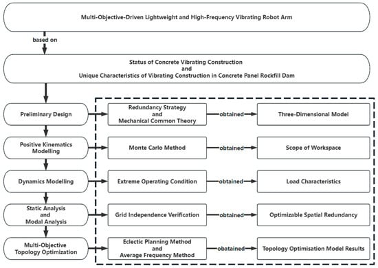
Figure 1.
Flow chart of the technical route of this research.
To help readers better understand the structural complexity and operational setup of concrete-faced rockfill dams (CFRDs), a typical configuration and construction orientation is shown in Figure 2. The figure illustrates how the VRA operates on the inclined concrete panels during the vibration process.
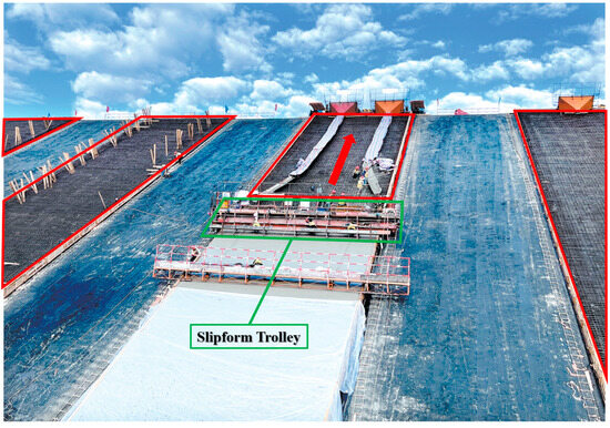
Figure 2.
Typical structure and construction orientation of a concrete-faced rockfill dam. Note: The red frame indicates the vibration area under typical CFRD working conditions, featuring inclined slabs, dense reinforcement, and an elevated operation height. The red arrow shows the upward insertion direction of the vibrator. The green frame denotes the slipform trolley system, on which the VRA is mounted. This system moves upward along the inclined panel during construction, enabling the robotic arm to perform layer-by-layer vibration from bottom to top.
Beyond the structural layout and vibration workflow illustrated in Figure 2, the on-site deployment of the vibrating robotic arm (VRA) must incorporate practical constraints, such as the limited swing range imposed by the slipform carriage and the restricted reachable workspace at the end effector. In addition, during layered top-down insertion on inclined formwork surfaces, the vibrator must remain perpendicular to the formwork in accordance with construction standards. Addressing these challenges, this study established a multi-objective topology optimization framework for the VRA. The framework integrates workspace reachability, load compliance, and vibration frequency requirements, with the specific aim of reducing structural mass, enhancing stiffness, and increasing modal frequencies to avoid resonance. In doing so, this research fills a gap in systematic structural optimization of vibrating robotic arms and provides a transferable approach for intelligent construction in complex dam environments.
2. VRA System
Preliminary Structural Design
To ensure the construction quality of the concrete panel rockfill dam, a preliminary design of the VRA’s overall structure was obtained in accordance with the process requirements of concrete vibrating. When selecting the configuration design scheme of the VRA, a serial robotic arm with a larger working space was selected, mainly to enhance the construction efficiency. This configuration was selected based on the working requirements of concrete vibration in inclined slab silos, which demand a wide reach and flexible posture adjustment. Compared with parallel or hybrid structures, serial arms offer a broader workspace, simpler kinematic modeling, and lower control complexity. These features also make them more suitable for integration with structural optimization methods. In contrast, parallel mechanisms are limited in motion range, and hybrid arms involve high manufacturing and control costs, which constrain their practical implementation in on-site applications. This design not only simplifies the subsequent structural design but also reduces the manufacturing cost, presenting significant advantages over the parallel-connected and mixed-connected mechanical arms.
Given the confined and irregular working environment of concrete vibration in panel rockfill dams, the serial configuration and multi-DOF design of the VRA provides flexibility in posture adjustment, which enhances its ability to operate around densely arranged rebar. Therefore, the components of the VRA primarily encompass the pedestal, rotating platform, connecting sleeve, main arm, mid-arm, forearm, end gripper, and additional parts. All of these components are movable on rotary axes, granting a total of five rotational degrees of freedom, specifically represented as , and in Figure 3. The coordinated movement of these components allows the end gripper to be adjusted to adapt to the height-directed reinforcement mesh of the inclined slab silo. This design not only meets the operational demands of vibrating but also exhibits a certain degree of obstacle avoidance capability.
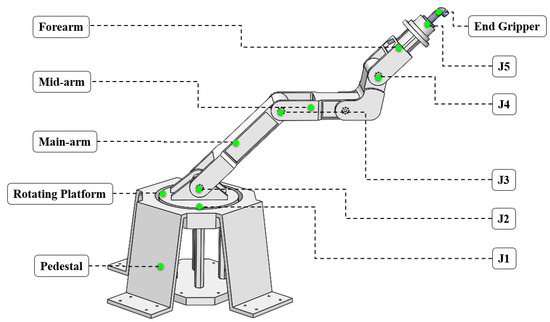
Figure 3.
Three-dimensional structural model.
In the context of the sizing and structural design of the components, a preliminary design was initially conceived, drawing upon traditional experience and general mechanical common theory. To ensure the reliability and safety of the overall structure, a strategy of redundant design was implemented. Once the structure and assembly relationship of each part of the robot arm had been ascertained, a three-dimensional model of VRA was constructed for subsequent design verification and optimization. The three-dimensional model is depicted in Figure 3. Since all the arm bodies were solid structures, their external geometry already reflected the internal layout, making additional sectional drawings unnecessary.
Given the substantial self-weight and extended arm span of the VRA, significant stress variations could potentially occur during its movement. This could potentially lead to the destruction of the articulated joints, thereby impacting the overall safety of the assembly. Therefore, in terms of material selection, high-strength structural steel, specifically the Q700 type, was utilized for the pedestal, the main arm, and the mid-arm in order to enhance its strength and stiffness and to ensure its reliability. However, for the forearm, cast aluminum was selected due to its lighter mass and the fact that the activity of its end joints is a rotation around the central axis of the forearm, which is subject to relatively minor forces and does not necessitate high strength. It is crucial that the quality of this material is light to avoid unnecessary stress. The properties of these two materials are shown in Table 1.

Table 1.
Main material properties.
3. Kinematics and Workspace Analysis
3.1. Positive Kinematics
Knowing the length of each connecting rod, assuming that the base coordinate system of the VRA is LC0, the local coordinate system of each joint and the coordinate system of the end of the VRA are LC1, LC2, LC3, LC4, LC5, LC6, LC7, LC8, and LC9, respectively, and the simplified coordinate system of the connecting rods is shown in Figure 4.
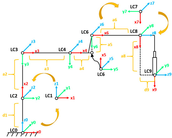
Figure 4.
Coordinate system of VRA.
Note: To ensure readability in the crowded coordinate system layout, certain local frames (e.g., LC1 and LC2) are spatially shifted and drawn near their actual positions. In cases where multiple coordinate frames are coincident or intermediate transformations are required (e.g., multi-step D-H conversions), auxiliary frames and directional arrows are used to illustrate the transformation logic. All rotational axes follow standard D-H conventions, with joint rotations defined about local z-axes.
To enhance clarity, each local coordinate system, LC0 to LC9, is explicitly marked on the mechanical structure in Figure 4. These coordinate systems correspond to key physical locations on the robotic arm, including the base, each joint, and the end-effector. The D-H parameter table (Table 2) was constructed based on these coordinate frames, with each row representing the relative transformation from frame LCi to LCi + 1.
Table 2.
Improved D-H parameter.
Specifically, the link numbering follows the physical sequence of the VRA: LC0 is fixed at the base, LC1–LC8 are placed at the centers of each revolute joint, and LC9 is located at the tip of the vibrator. This mapping ensures that the parameters θ, d, a, and α in the D-H table directly reflect the geometric and rotational relationships between neighboring links. This improved mapping supports accurate derivation of the transformation matrix and subsequent workspace analysis.
An improved D-H parameter table [36] was obtained based on the linkage coordinate system of VRA, as shown in Table 2.
The kinematic model was established in this work, drawing upon an improved D-H parameter table [37]. This model facilitates the derivation of transformation matrices, denoted as , and , which represent the transformations between neighboring coordinate systems. The final transformation matrix, denoted as , is obtained by sequential concatenated multiplication of these matrices. This final matrix encapsulates the orientation of the vibrator end coordinate system relative to the base coordinate system of the robot arm. Mathematically, this is expressed as
For the sake of simplicity in subsequent equations, the following abbreviations are defined:
represents the rotation matrix of the vibrator end coordinate system with respect to the base coordinate system of the robot arm. This matrix is denoted as
0P8 denotes the position vector of the origin of the vibrator end coordinate system with respect to the base coordinate system of the robotic arm. This vector is represented as
Included among these are
The simplified form of is
Using the corresponding joint angle change values, the positional information of the endpoint of the VRA relative to the base coordinate system of the VRA could be computed via the transformation matrix. To validate the precision of the established kinematic equations of the VRA, a simulation model was generated by the Robotics System Toolbox (v3.4, MATLAB R2021b, MathWorks Inc., Natick, MA, USA) in accordance with the updated D-H parameter table. Herein, the red cylinders amidst the connecting rods represent the rotating joints, i.e., , and , while the blue cylinders are the fixed joints. By simulating the rotation of these joints, three representative postures were obtained: the initial hibernation posture, used to illustrate the arm’s ability to retract in confined spaces; the close-to-pedestal operating posture, representing the configuration required to operate at the lower edge of the inclined slab formwork; and the linkage coordinate system posture, used to validate the maximum reachable range of the end-effector. These configurations are depicted in Figure 5a, Figure 5b and Figure 5c respectively. Ultimately, by comparing the simulation model with the analytical kinematic model, the consistency between the mathematical equations and the joint relationships in the simulation was confirmed.
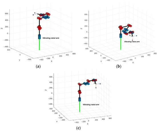
Figure 5.
Interactive kinematic simulation models. (a) Initial hibernation posture. (b) Close-to-pedestal operating posture. (c) Linkage coordinate system posture.
3.2. Workspace Analysis of Monte Carlo Method
The workspace of a robotic arm is a crucial indicator for evaluating its performance. The Monte Carlo method [38] is a numerical computation technique [39] that was used to establish the comprehensive working range of the arm as comprehensively as possible. This process involved the generation of a large number of random samples of the joint angles of the VRA to ensure a wide representation of the working conditions of the arm. These angle samples were then substituted into the positive kinematic equation delineated in Section 3.1 to determine the corresponding position of the endpoint of the VRA. With an ample number of samples, the collective random values at the endpoints formed a comprehensive workspace for the VRA. The number of random points, denoted as N, was set to 500,000, considering factors such as cloud density and computer performance. The three-dimensional view, top view, front view, and left view of the point cloud of the workspace of the five-degree-of-freedom VRA are depicted in Figure 6a, Figure 6b, Figure 6c and Figure 6d, respectively. The point cloud was generated using uniformly distributed Monte Carlo sampling (N = 500,000), ensuring sufficient density and coverage of the workspace. These figures provide a visual representation of the workspace, where the distribution exhibits uniformity without noticeable voids, thus confirming the absence of dead zones.
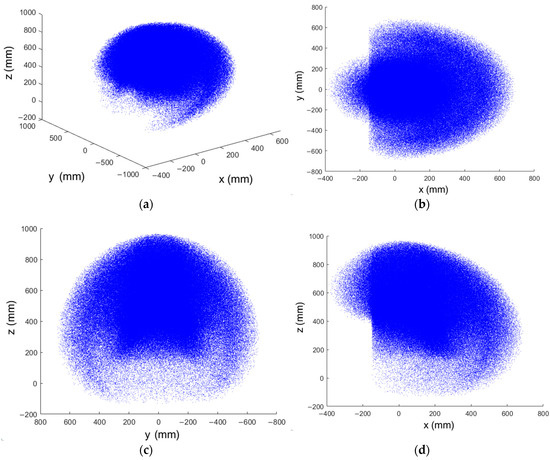
Figure 6.
Point cloud maps of workspace. (a) Three-dimensional view. (b) Top view. (c) Front view. (d) Left view.
From Figure 6, it is clear that the workspace of the robotic arm’s shape resembles that of a helmet filled inwardly. The overall length of the workspace is within a maximum range of 1.368 m, while the maximum working width is 0.838 m. The distribution of the point cloud within this space exhibits uniformity and rationality, with no noticeable voids. This observation confirms that the end of the arm can reach any point within the workspace, thus ensuring the absence of “dead zones” within the workspace. Furthermore, the range of the workspace and its distribution are largely consistent with the actual requirements. This not only validates the rationality of the structural parameters of the robotic arm’s design but also provides robust assurance for its performance in real-world applications.
It should also be emphasized that the optimization process in this study focused exclusively on material removal and structural weight reduction through multi-objective topology optimization. The geometric parameters of the robotic arm, including link lengths and joint angle limits defined by the D-H parameters, remained unchanged. Therefore, the workspace characteristics were not affected by the optimization, while the improvements were mainly reflected in reduced mass, increased modal frequencies, and enhanced vibration adaptability.
4. Load Characteristics
During the operational process of a VRA, the loading condition of each arm plays a crucial role as a fundamental basis for subsequent static analysis, modal analysis, and optimization design [40]. The task of obtaining the load of each arm is, in essence, an inverse dynamics problem. This means, given the state of motion of the arm under specific working conditions, the driving force and moment of the arm are sought. Given that the design of this VRA was a five-degree-of-freedom system, and its motion state was complex and contained numerous force nodes, it became challenging to analyze and solve the inverse dynamics problem by formulating the dynamics equations [41]. Therefore, to tackle this issue, dynamic simulation calculations were performed on the VRA to acquire the loading characteristics of the vital components of the mechanical arm.
4.1. Dynamics Simulation
4.1.1. Dynamics Simulation Modeling
Initially, the three-dimensional model developed in Section Preliminary Structural Design was simplified. Subsequently, the respective material properties were assigned to each component. According to the interconnection between the components, the corresponding kinematic vices were established. Specifically, the end members of , and needed to be connected via a rotating vice, while the remaining adjacent members were linked via a fixed vice. Additionally, to simulate a VRA that is gripping a 20 kg vibrating rod, a 20 kg load was applied to the end gripper. It is crucial to note that due to the extended length of the VRA and the relatively significant mass of the components, the impact of gravity should not be underestimated, and a downward gravitational acceleration should be incorporated into the overall simulation model. Ultimately, to accurately gauge the output force and moment information, marker measurement points were incorporated at the joints. The specific marker measurement points and the position of the motion vice are depicted in Figure 7.
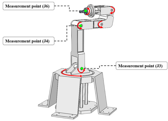
Figure 7.
Dynamic simulation model.
The entire simulation process was conducted in the ADAMS environment (v2020, MSC Software Corp., Newport Beach, CA, USA), which enabled accurate modeling of the joint behavior and load response under high-frequency conditions.
4.1.2. Load Characteristics Under Extreme Operating Conditions
When the arms and joints of the VRA move in unison, with all of them located within the same plane and maintaining a horizontal state, the load each arm bears reaches its maximum [42]. This is also the most hazardous posture of the VRA. In this configuration, all the links of the VRA are horizontally aligned in a single plane, leading to the maximum effective extension of the arm. This causes the center of gravity to be positioned at the furthest distance from the base, thereby inducing the largest bending moments and torques at the joints. Moreover, the overall stiffness of the structure is minimized, and flexibility is maximized, making it highly susceptible to deformation or dynamic instability under external excitations. Therefore, this posture is commonly considered the most critical for assessing structural reliability and was selected as the worst-case scenario for load analysis. Upon the encounter of load arising from extreme operating conditions, it was empirically evident that such loads are capable of satisfying the mechanical performance requirements of the vibrating robotic arm across the majority of operating conditions. In light of these extreme operating conditions and the movement parameters of the VRA, a corresponding rotary drive was integrated into the rotating vice at the joints, with the appropriate drive function being set to simulate the movement process under the most perilous operating conditions. The motion process under this condition is depicted in Figure 8.
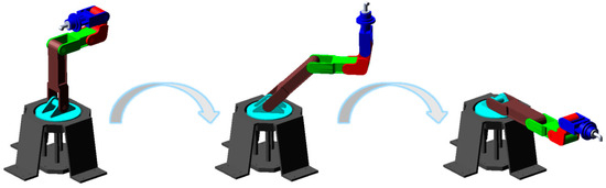
Figure 8.
Motion process in extreme operating conditions.
The curves representing the force applied to the main arm, mid-arm, and forearm in real-time under the extreme operating condition are depicted in Figure 9a, Figure 9b and Figure 9c, respectively.
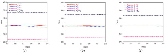
Figure 9.
Real-time curves of the applied force. (a) Main arm. (b) Mid-arm. (c) Forearm.
The figures presented below illustrate the real-time curves of the moments acting on the main arm, mid-arm, and forearm under the extreme operating condition. These are depicted in Figure 10a–c.
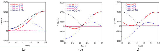
Figure 10.
Real-time curves of the applied torque. (a) Main arm. (b) Mid-arm. (c) Forearm.
Extracting the maximum instantaneous loads for three arms during uniform motion, these values represent the maximum effective loads under the extreme operating condition for each arm. These load data serve as a fundamental basis for subsequent static, modal, and optimization design analyses. Upon this foundation, a more in-depth analysis and optimization design could be conducted to enhance the performance and safety of the robotic arm.
In addition, it is important to consider the long-term implications of repeated operation under such extreme conditions. While the maximum forces and torques serve as critical load boundaries, cyclic exposure may accelerate fatigue damage in structural components. To mitigate these risks, the optimized design emphasized weight reduction while maintaining stiffness and raising natural frequencies, thereby reducing susceptibility to resonance. Such improvements provided additional safety margins for the long-term stability and durability of the robotic arm during continuous high-frequency vibration tasks.
5. Static–Dynamic Characteristics
To confirm that there was room for optimization of the vibrating robotic arm, it was necessary to obtain its static and dynamic characteristics through FEA. This also ensured that the VRA exhibited optimal static characteristics (strength and stiffness) and dynamic characteristics (vibration pattern and intrinsic frequency) during operation. And to prevent any undesirable phenomena, such as excessive deformation, premature destruction, and homogeneous resonance from arising, it was essential to conduct comprehensive static and modal analyses on the three arms. Therefore, the main arm, mid-arm, and forearm served as the primary research subjects. Based on the load characteristics of each arm, detailed in Section 3, static and modal analyses were conducted on the models of the three arms, with the aim of obtaining key indicators, such as their stresses, strains, modal frequencies, and vibration shapes. Furthermore, the results derived from the aforementioned finite element analysis provided the necessary response information data for the topology optimization design of the VRA in Section 5. These data could serve as driving objectives or constraints for the optimization design.
5.1. Mesh Independence Verification
Each of the simplified arm models was assigned its corresponding material properties. Subsequently, a three-dimensional model was constructed. Mesh generation is one of the most crucial stages in FEA [16,43]. The key step in this process is to determine the optimal mesh size. In the realm of FEA, the nodes of the grid elements are typically employed as the fundamental computational units. Consequently, the count of these nodes can, to some extent, reflect the speed of finite element computation. Meanwhile, the accuracy of the computation can be evaluated by examining the limiting rate of change, which encompasses the limiting stress rate of change and the limiting deformation rate of change. The smaller these two parameters, the less impact the mesh size has on the solution outcomes, thereby enhancing the accuracy of the solution. To enhance computational efficiency while maintaining the precision of the results, it is imperative to validate the mesh independence for each arm model [16]. For this validation, stress and deformation were used as the primary objective functions, and the specific function formulae were as follows:
In Equations (9) and (10), represents the rate of change in ultimate stress, while denotes the rate of change in ultimate deformation.
and refer to the ultimate stress values (in MPa) corresponding to element sizes m and n, respectively.
and represent the ultimate deformation values (in mm) obtained using element sizes m and n, respectively.
To ascertain the optimal mesh size, a series of finite element models were systematically established, each with mesh sizes of 10 mm, 9 mm, 8 mm, 7 mm, and 6 mm, respectively. These models were then used to solve for the resulting stresses and deformations. Simultaneously, utilizing the aforementioned mesh independence verification Formulae (9) and (10), we calculated the limiting rates of change, denoted as and , for each of the different mesh sizes. The specific computation outcomes are enumerated in Table 3. Similarly, the corresponding mesh quality results for the mid-arm and forearm are listed in Table 4 and Table 5, respectively.
Table 3.
Main arm grid quality.
Table 4.
Mid-arm grid quality.
Table 5.
Forearm grid quality.
Additional analysis of the finite element mesh quality table for the main arm revealed that when the mesh size was reduced from 7 mm to 6 mm, the number of nodes of the main arm increased by 23.43%. However, the rates of change in the ultimate stress and ultimate deformation only decreased by 8.49% and 33.75%, respectively. This suggests that although the speed of the finite element calculation was reduced, the calculation accuracy was not significantly improved. Consequently, in pursuit of a more accurate finite element calculation model, the mesh size was reverted to 7 mm. At this size, the number of elements was 21,069, and the number of nodes was 33,762.
Consistent results were observed in the examination of the mid-arm and forearm. When the mesh size was narrowed from 8 mm to 7 mm, the augmentation in the quantity of nodes for the mid-arm and forearm, respectively, escalated by 17.56% and 14.6%, whereas the corresponding augmentation in ultimate stress only diminished by 23.73% and 35.20%, and the corresponding augmentation in ultimate deformation only diminished by 35.44% and 14.20%. This suggests that although the computational speed was slightly reduced, it did not significantly enhance the computational accuracy. Consequently, the mesh size for both the mid-arm and forearm was set at 8 mm to optimize the finite element model, which yielded a mid-arm model composed of 22,058 elements and 33,463 nodes, and a forearm model composed of 22,467 elements and 34,175 nodes.
5.2. Acquisition of Static Characteristics
The main arm, mid-arm, and forearm were meshed according to the mesh size, as determined in Section 4.1. Prior to calculating the static characteristics for each arm, it was also imperative to establish the boundary conditions for each arm. Specifically, a fixed constraint was imposed on J2 of the main arm, and the load characteristics of the main arm under the most hazardous operating conditions were imposed at J3. A fixed constraint was imposed on J3 of the mid-arm, and the load characteristics of the mid-arm under the most hazardous operating conditions were imposed at J4. A fixed constraint was imposed on J4 of the forearm, and the load characteristics of the small arm under the most hazardous operating conditions were imposed at J5. The boundary conditions for the three arms are depicted in Figure 11a, Figure 11b and Figure 11c, respectively.
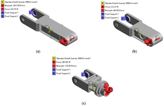
Figure 11.
Setting of loads and constraints. (a) Main arm. (b) Mid-arm. (c) Forearm.
Upon completion of the import process for the finite element model, a series of operations, including meshing and boundary condition settings, were executed. Subsequently, the static mechanics module was in the solution process. The outcomes of this process included the computation of the maximum deformation and maximum stress for each arm, which are enumerated in Table 6.
Table 6.
Static characteristics under extreme operating conditions.
Upon reviewing the table presented, it is evident that the maximum stress value for each arm was significantly lower than the material’s permissible strength. This not only satisfies the strength prerequisites for the utilization of each arm but also boasts an ample margin of safety. Consequently, these components possess significant room for optimization.
5.3. Acquisition of Dynamic Characteristics
Section 4.1 developed a finite element model encompassing the principal components of the system, including the application of boundary conditions and the specification of material properties. This model formed the foundation for analysis, upon which we applied the modal analysis module. Through this module, we were able to calculate and deduce the first three order frequencies and corresponding vibration patterns of each arm. The outcomes of this analysis provide valuable insights into the dynamic behavior of the system, which can further inform its optimization.
Figure 12a, Figure 12b and Figure 12c, respectively, present the vibration cloud diagrams of the first three order modes of the main arm. The detailed expressions are as follows:
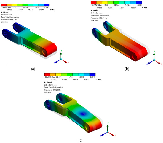
Figure 12.
Cloud diagrams of the first three order modes of main arm. (a) First-order mode. (b) Second-order mode. (c) Third-order mode.
- (1)
- The first-order vibration mode exhibits an up-and-down oscillation along the y-axis;
- (2)
- The second-order vibration mode involves a left-and-right oscillation along the z-axis;
- (3)
- The third-order vibration mode is characterized by a twist around the y-axis.
The diagrams depicting the vibration clouds of the first three order modes of the mid-arm are shown in Figure 13a, Figure 13b and Figure 13c, respectively. The detailed descriptions are as follows:
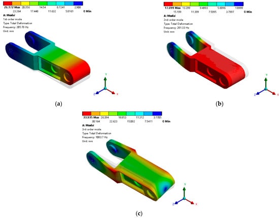
Figure 13.
Cloud diagrams of the first three order modes of mid-arm. (a) First-order mode. (b) Second-order mode. (c) Third-order mode.
- (1)
- The first-order vibration mode exhibits an up-and-down oscillation along the y-axis;
- (2)
- The second-order vibration mode demonstrates a left-and-right oscillation along the z-axis;
- (3)
- The third-order vibration mode involves a twisting motion around the x-axis.
Figure 14a, Figure 14b and Figure 14c present the vibration cloud diagrams of the first three orders of the forearm, respectively. The specific vibration patterns are detailed as follows:
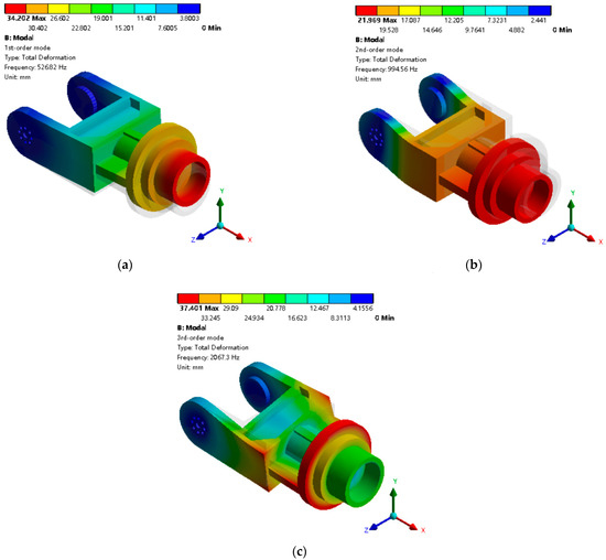
Figure 14.
Cloud diagrams of the first three order modes of forearm. (a) First-order mode. (b) Second-order mode. (c) Third-order mode.
- (1)
- The first-order vibration mode exhibits an up-and-down oscillation along the y-axis;
- (2)
- The second-order vibration mode demonstrates a left-and-right oscillation along the z-axis;
- (3)
- The third-order vibration mode is characterized by a twist around the x-axis.
Upon analyzing the dynamic characteristics, it is evident that the dynamic deformation is notably greater than the static deformation when each arm is in a state of the same frequency resonance. The reason for the greater dynamic deformation lies in the amplification effect near resonance. When the natural frequencies of the main arm and mid-arm are close to the vibrator’s operating frequency range (25–200 Hz), the vibration patterns couple with the external excitation, resulting in larger displacement responses compared with static loading. This highlights the necessity of increasing the low-order modal frequencies through optimization to shift them away from the operational band, thereby improving dynamic stability and reducing resonance risks. It is important to emphasize that the vibration frequency produced by the vibrating rod during operation is typically between 25 Hz and 200 Hz, with the first-order modal frequencies of the main arm and mid-arm falling within this range. Therefore, it is imperative to elevate the low-order modal frequencies as an objective in the process of topology optimization. The findings from the aforementioned analysis serve as a crucial reference in the realm of design optimization and safety assessment.
In the initial design phase, a redundancy strategy was adopted to ensure structural safety under high-frequency vibration, using traditional sizing and high-strength materials without optimization. However, static and dynamic analyses revealed issues such as excessive weight, low modal frequency, and high flexibility, making the structure vulnerable to resonance and inefficient for vibration tasks. Therefore, topology optimization is required to reduce mass, increase modal performance, and enhance high-frequency adaptability.
6. Multi-Objective-Driven Topology Optimization
To ensure the reliability and safety of the overall structure’s performance of the VRA, the preliminary design scheme incorporated a redundancy strategy. The results of the static analysis of the VRA revealed that each arm possessed a significant safety margin, indicating room for optimization. Specifically, by forgoing a portion of the excess performance index, the comprehensive performance could be enhanced [43]. Furthermore, the findings of the modal analysis conducted on the VRA revealed a significant susceptibility to the phenomenon of same-frequency resonance. This implied that there existed potential for optimization within this system, and it must be optimized.
6.1. Mathematical Model Based on Eclectic Planning Method and Average Frequency Method
For the specific case of a VRA gripping a high-frequency vibrator’s operation, an eclectic planning method [44] was employed to integrate both the low-order frequency and the flexibility value. These two elements are crucial objectives in the optimization of the drive topology. It should be noted that the closeness of the low-order frequency to the vibrator’s operating frequency has a more significant impact on the structure’s performance; thus, the prioritization of the low-order frequency optimization was heightened accordingly. To this end, the average frequency method was adopted, which assigns weights to each order frequency by analyzing the minimum difference between the first three order modal frequencies and the vibrator’s operating frequency.
Finally, a mathematical model for multi-objective topology optimization was established, utilizing both the average frequency method and the eclectic planning method, grounded on the variable density method of SIMP [45,46]. This model incorporates the mass fraction as a constraint and aims to achieve lightweight while maximizing the low-frequency ratio, simultaneously minimizing the flexibility index. Consequently, a mathematical model that is adapted to both static and dynamic topology optimization under multiple operating conditions was obtained.
In the equation, represents the pseudo-density vector of elements for the pseudo-density value of element i ([0, 1] interval); represents the multi-objective integrated optimization function denote the mass before optimization and the mass after optimization (kg).
Included among these are
In the equation, denotes the weights for static and dynamic operating conditions ([0, 1] interval); denotes the flexibility value objective function denotes the maximum flexibility value and the minimum flexibility value; q denotes the penalty factor denote the maximum average frequency and the minimum average frequency.
Included among these are
In the equation, denotes the average frequency objective function denotes the adjustment parameter for the objective function ([0, 1] interval); denotes the weighting coefficients ([0, 1] interval) for the frequency order considered for optimization denotes the modal frequency of order i.
To clarify the rationale of the optimization strategy, the weighting coefficients in the compromise programming method were determined by normalizing the relative importance of stiffness and dynamic performance, based on the sensitivity analysis of modal frequency and flexibility. Specifically, higher priority was assigned to low-order modal frequency improvement, since the resonance risk is closely tied to the vibrator’s operating frequency range. The constraints were set on mass fraction (to ensure a lightweight design) and on the feasible range of pseudo-density values (to ensure manufacturability). The average frequency strategy was then applied to balance the contributions of the first three modal frequencies, with weights proportional to their deviation from the vibrator’s frequency range. This integrated formulation ensured that the optimization results simultaneously reduced mass, enhanced stiffness, and elevated critical modal frequencies, thus improving the vibration resistance under high-frequency working conditions.
6.2. Results of Topology Optimization
The multi-objective optimization scheme was implemented through the multi-objective static–dynamic topology optimization mathematical model established in Section 5.1. The results of the comprehensive topology-optimized model for the main arm, mid-arm, and forearm, with the material distribution after removing the pseudo-density values below 0.3, were obtained as shown in Figure 15a, Figure 15b and Figure 15c, respectively.
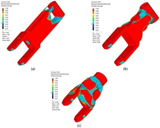
Figure 15.
Multi-objective topology-optimized model. (a) Main arm. (b) Mid-arm. (c) Forearm.
In the course of the optimization iterations, the first-order modal frequency iteration curve, the flexibility value iteration curves, and the multi-objective equation value iteration curves are depicted in Figure 16a, Figure 16b and Figure 16c. Only the iterative curves for the first-order modal frequencies are displayed, as the second- and third-order modal frequencies of each arm, which were largely within the safe range, were significantly higher than the 200 Hz maximum operating frequency of the vibrator. Consequently, the focus is on the iterative curves for the first-order modal frequencies that fell within the range of the vibrator bar’s operating frequency. These figures simultaneously showcase the comprehensive optimization of three arms, providing a comprehensive view of the iterative changes in the different parameters during the optimization process.
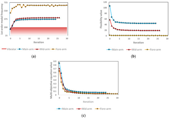
Figure 16.
Iterative curves of performance indicators. (a) First-order modal frequency. (b) Flexibility value. (c) Multi-objective equation value.
As shown in Figure 16, the iterative trends of the modal frequency, flexibility, and multi-objective function clearly demonstrate rapid improvements and convergence during optimization. The specific quantitative results, such as mass halving, flexibility reduction, and modal frequency enhancement, are further summarized in Section 7.
The findings indicate that the flexibility values of the three arms exhibited a downward trend as the number of iterations increased. Simultaneously, the mass of the design region was halved, which implies an improvement in the mechanical properties. Concurrently, the first-order modal frequencies escalated beyond the vibrator operating frequency, thereby preventing same-frequency resonance phenomena. This outcome aligns closely with the anticipated pattern of the target iterations.
Furthermore, the corresponding analyses carried out during the preliminary design phase were validated. Due to the movement of the end joints and the material utilized for the forearm, the forearm was subjected to relatively lower forces. Consequently, the performance of the forearm was superior to that of the main arm and mid-arm, and the impact of the optimization iterations on it was not as evident as on the main arm and mid-arm.
7. Conclusions
To address the challenges of concrete vibration in the construction of rockfill dam panels, this study developed a specialized vibrating robotic arm (VRA). This design aimed to overcome the limitations of traditional mechanized vibrating equipment, the high labor costs, the high work intensity, and the inefficiencies of the construction process. The design was based on an objective-driven topology optimization method, which was used to achieve a lightweight and high-frequency design for the main arm, mid-arm, and forearm, leading to significant results, including reduced mass, increased modal frequencies, and decreased flexibility values.
- An optimized design implementation process was presented, which not only provides a theoretical basis but also offers a reference for the design and optimization of lightweight and high-frequency VRA structures. This process is both reasonable and feasible, ensuring that the implementation can be effectively carried out in practice.
- The high-frequency optimization design of the VRA resulted in varying degrees of increases in the modal frequencies of each arm. Among these, the first-order modal frequencies of the arms that were closest to the operating frequency of the vibrator were, respectively, increased from 158.08 Hz, 172.201 Hz, and 502.67 Hz to 367.57 Hz, 404.55 Hz, and 664.40 Hz, which are largely within the safe range and are significantly higher than the 200 Hz maximum operating frequency of the vibrator. This effective increase can prevent the occurrence of same-frequency resonance phenomena, which damage the structure. These values correspond to the first-order modal frequencies of each arm, which are critical for vibration stability, as they fall close to the vibrator’s operating frequency range.
- Through the multi-objective optimization design of the VRA, the flexibility values were, respectively, reduced from 106.05, 57.34, and 1.72 to 43.88, 19.24, and 0.58, indicating an enhancement in the stiffness of the individual arms. Simultaneously, the mass of the design region was halved. This implies a certain level of synchronization and optimization of the mechanical properties.
In the course of this research to obtain the specific results described above, (1) a preliminary design and three-dimensional modeling of the VRA was obtained, taking into account the status of a concrete vibrating construction and the unique characteristics of the vibrating construction in the concrete panels of rockfill dams, based on redundancy strategies, experience, and general mechanical common theory. (2) The kinematic analysis of the VRA was completed, based on the improved D-H parameter table, to establish the positive kinematics equations. (3) The interactive simulation of the positive kinematics model was successfully completed. (4) The workspace of the VRA, which was obtained by combining the Monte Carlo method and positive kinematics, was investigated. (5) The dynamic simulation of the VRA under the most dangerous working conditions was completed, and the load characteristics of each arm were obtained. (6) The static–dynamic characteristics of each arm under the respective load characteristics were investigated, and the safety margin was obtained by comparing the corresponding material performance parameters. (7) A mathematical model for multi-objective topology optimization based on the eclectic planning method and the average frequency method was developed in order to integrate important performance indicators. This can serve as an important reference index for the optimization of the design.
By optimizing the design of the VRA for lightweight and high-frequency operation, the system is enabled to adapt effectively to demanding vibration conditions, leading to notable improvements in operational sensitivity, efficiency, and safety. Moreover, the optimized design contributes to reductions in cost and energy consumption, thereby enhancing both the performance and market competitiveness of the VRA. Beyond immediate project benefits, these outcomes provide substantial value for the construction industry by supporting safer, more efficient concrete vibration in dam panel construction. At the same time, the integration of multi-objective topology optimization into robotic arm design offers a transferable framework for broader applications in intelligent manufacturing and automation. Collectively, the proposed design not only generates significant economic and social benefits but also advances concrete vibratory construction toward a higher standard of “quality” and “intelligence.”
Author Contributions
Conceptualization, Z.W.; Methodology, Y.G. and S.Q.; Validation, J.S.; Formal analysis, J.H.; Investigation, Y.G. and J.S.; Resources, Z.W.; Writing—review & editing, Y.G. and J.H.; Supervision, J.S., H.L. and S.Q.; Project administration, H.L. All authors have read and agreed to the published version of the manuscript.
Funding
This research received no external funding.
Data Availability Statement
The data presented in this study are available on request from the corresponding author. The data are not publicly available due to institutional data management restrictions.
Conflicts of Interest
Author Yuannan Gan, Zhigang Wu, and Jifeng Hu were employed by the company China Anneng Group Second Engineering Bureau Co., Ltd. The remaining authors declare that the research was conducted in the absence of any commercial or financial relationships that could be construed as a potential conflict of interest.
References
- Zhu, S. Research on construction technology of concrete panel rockfill dam in pumped storage power station project. Sci. Technol. Wind 2021, 28, 120–122. [Google Scholar] [CrossRef]
- Yangtze River Institute of Surveying. Planning and Design. Specification for Hydraulic Concrete Construction; China Water Conservancy and Hydropower Press: Beijing, China, 2014. [Google Scholar]
- China Electricity Council. Hydraulic Concrete Construction Specification; China Electric Power Press: Beijing, China, 2015. [Google Scholar]
- Du, Y.; Li, C.; Chen, F.; Wang, J.; Yue, Y.S. A review on the development of concrete leveling vibrating machine. Water Conserv. Hydropower Technol. 2020, 51, 99–110. [Google Scholar] [CrossRef]
- Zhang, Z.; Qiang, S.; Zheng, Z.; Du, R.; Ding, B. Design of automatic vibration system for reinforced concrete based on STM32 and OPENMV. Autom. Technol. Appl. 2020, 39, 181–183, 186. [Google Scholar]
- Liang, H.; Wu, Z.; Hu, J.; Gan, Y.; Qiang, S. Simulation test of an intelligent vibration system for concrete under reinforcing steel mesh. Buildings 2024, 14, 2277. [Google Scholar] [CrossRef]
- Li, T.; Wang, H.; Tan, J.; Kong, L.; Jiang, D.; Pan, D.; Zhang, C. A continuous concrete vibration method for robots based on machine vision with integrated spatial features. Appl. Soft Comput. 2024, 167 Pt A, 112231. [Google Scholar] [CrossRef]
- Li, M.; Li, C.; Qian, H.; Chu, Y. Trajectory planning of concrete vibration robot in rebar mesh on dam surface. Mach. Electron. 2023, 41, 61–65. [Google Scholar]
- Li, J.; Tian, Z.; Sun, X.; Ma, Y.; Liu, H. Working state determination for concrete internal vibrator using genetic simulated annealing clustering method. Case Stud. Constr. Mater. 2022, 17, e01163. [Google Scholar] [CrossRef]
- Ren, B.; Zheng, X.; Guan, T.; Wang, J. Vibrator rack pose estimation for monitoring the vibration quality of concrete using improved YOLOv8-Pose and vanishing points. Buildings 2024, 14, 3174. [Google Scholar] [CrossRef]
- Ma, Y.; Tian, Z.; Xu, X.; Liu, H.; Li, J.; Fan, H. Research on response parameters and classification identification method of concrete vibration process. Materials 2023, 16, 2958. [Google Scholar] [CrossRef]
- Fan, S.; He, T.; Li, W.; Zeng, C.; Chen, P.; Chen, L.; Shu, J. Machine learning-based classification of quality grades for concrete vibration behaviour. Autom. Constr. 2024, 167, 105694. [Google Scholar] [CrossRef]
- Li, J.; Tian, Z.; Yu, X.; Xiang, J.; Fan, H. Vibration quality evaluation of reinforced concrete using energy transfer model. Constr. Build. Mater. 2023, 379, 131247. [Google Scholar] [CrossRef]
- Yang, F.; Zeng, X.; Xia, Q.; Yang, L.; Cai, H.; Cheng, C. Early detection and analysis of cavity defects in concrete columns based on infrared thermography and finite element analysis. Materials 2025, 18, 1686. [Google Scholar] [CrossRef]
- Shardakov, I.; Shestakov, A.; Glot, I.; Gusev, G.; Epin, V.; Tsvetkov, R. Piezoceramics actuator with attached mass for active vibration diagnostics of reinforced concrete structures. Sensors 2024, 24, 2181. [Google Scholar] [CrossRef] [PubMed]
- Ahmed, H.; Kuva, J.; Punkki, J. Analysing Entrapped Pores in Concrete via X-ray Computed Tomography: Influence of Workability and Compaction Time. Constr. Build. Mater. 2024, 417, 135322. [Google Scholar] [CrossRef]
- Liu, Y.; Gan, Y.; Yang, Z.; Qiang, S. Intelligent Construction Technology for Reservoir Dams. Autom. Constr. 2025, 175, 106177. [Google Scholar] [CrossRef]
- Ye, H.; Su, Y. Research and exploration on promoting the transformation and development of construction industry with new quality productivity. J. Eng. Manag. 2024, 38, 1–5. [Google Scholar] [CrossRef]
- Yang, B.; Lu, X. Research on lightweight design method of robotic arm. Agric. Equip. Veh. Eng. 2022, 60, 129–133. [Google Scholar]
- Sun, L.; Xu, H.; Wang, Z.; Chen, G. Overview of key common technologies for intelligent application of industrial robots. Vib. Test Diagn. 2021, 41, 211–219. [Google Scholar] [CrossRef]
- Zhang, H.; Wang, Y.; Sun, X. Multi-objective topology optimization for lightweight robotic arms considering vibration resilience. Mech. Mach. Theory 2023, 184, 105202. [Google Scholar] [CrossRef]
- Liu, Z.; Tian, S.; Dai, Z.; Gao, L. Strength analysis and optimal design of gripping robotic arm. Mech. Des. Manuf. 2024, 214–218, 225. [Google Scholar] [CrossRef]
- Yi, X.; Xiao, H. Lightweight design of tractor bodies based on damped vibration damping materials. Agric. Mech. Res. 2025, 47, 253–257. [Google Scholar] [CrossRef]
- Zhao, X.; Cao, G.; Zhang, P.; Ma, Z.; Zhao, L.; Chen, J. Dynamic analysis and lightweight design of a three-degree-of-freedom apple picking robot arm. J. Agric. Mach. 2023, 54, 88–98. [Google Scholar]
- Liu, G.; Guan, D.; Shi, L.; Song, X.; Lu, G. Structural finite element analysis and optimization design of a special robotic arm for forging. Forg. Technol. 2024, 49, 160–165, 178. [Google Scholar] [CrossRef]
- Liao, L.; Meng, W.; Zhang, R.; Sun, Z. Joint flange design of hybrid structure robotic arm based on topology optimization and orthogonal analysis. J. Donghua Univ. (Nat. Sci. Ed.) 2024, 6, 57–64. [Google Scholar] [CrossRef]
- Zhu, J.; Cai, X.; Ma, D.; Zhang, J.; Ni, X. Improved structural design of wind turbine blade based on topology and size optimization. Int. J. Low-Carbon Technol. 2022, 17, 69–79. [Google Scholar] [CrossRef]
- Chen, Z.; Zhang, J.; Wu, B. Lightweight design of one arm of concrete pump truck based on topology optimization. China J. Constr. Mach. 2019, 17, 238–242. [Google Scholar] [CrossRef]
- Hou, J.; Wang, Y.; Zhong, Y.; Zhao, D.; He, W.; Zhou, F. Lightweight design of body-in-white structure based on adaptive response surface method. Sci. Technol. Eng. 2024, 24, 3416–3425. [Google Scholar]
- Zeng, Q. Structural Design and Optimization of Vibrating Robot Arm. Master’s Thesis, Chang’an University, Xi’an, China, 2023. [Google Scholar] [CrossRef]
- Zhou, R. Lightweight Robot Design Based on Multi-Objective Topology Optimization. Master’s Thesis, Soochow University, Suzhou, China, 2017. [Google Scholar]
- Hu, Q.; Zhou, S. Multi-objective reliability topology optimization for industrial robots considering rigid-flexible coupling. Comput. Integr. Manuf. Syst. 2020, 26, 623–631. [Google Scholar] [CrossRef]
- Wen, S. Design of Spider Aerial Working Platform and Its Structural Analysis and Optimization. Master’s Thesis, Shandong University, Jinan, China, 2021. [Google Scholar] [CrossRef]
- Huang, H. Research on Lightweight Design of Industrial Robotic Arm. Ph.D. Thesis, Harbin Institute of Technology, Harbin, China, 2021. [Google Scholar] [CrossRef]
- Dai, Z. Research on the Dynamics and Stiffness of a Class of Kinematic Redundant Hybrid Mechanism. Ph.D. Thesis, Yanshan University, Qinhuangdao, China, 2018. [Google Scholar]
- Liu, X.; Qiu, C.; Zeng, Q.; Li, A. Kinematics analysis and trajectory planning of collaborative welding robot with multiple manipulators. Procedia CIRP 2019, 81, 1034–1039. [Google Scholar] [CrossRef]
- Yu, Z.; Ren, H.; Qin, Q.; Hu, K. Kinematic analysis and trajectory planning of welding robot for complex spatial paths. J. Wuhan Univ. Sci. Technol. 2023, 46, 384–392. [Google Scholar]
- Yang, K.; Huang, J. Kinematics and workspace analysis of an 8-degree-of-freedom spatial robotic arm. Mech. Transm. 2021, 45, 147–152. [Google Scholar] [CrossRef]
- Liu, X.; Lu, X.; Zhao, S. Three methods for solving the workspace of the climbing tower of electric power tower. J. Mech. Des. 2012, 29, 10–14. [Google Scholar]
- Ouyang, X. Finite Element Analysis of Humanoid Robot. Ph.D. Thesis, Tsinghua University, Beijing, China, 2003. [Google Scholar]
- Bai, Q.; Kong, Q.; Zhao, Q. Dynamic modelling and simulation of a soft continuous robotic arm. J. Mech. 2022, 54, 184–195. [Google Scholar]
- Zhang, X.; Do, P.; Kong, L. Wave loading in local structural design of ultra-deepwater semi-submersible platforms. Ship Sci. Technol. 2021, 43, 105–109. [Google Scholar]
- Du, P. Basic principles of finite element meshing. Mech. Des. Manuf. 2000, 1, 34–36. [Google Scholar]
- Wang, J.; Zhong, J.; Luo, J. Parametric modelling method for skiff. J. Huazhong Univ. Sci. Technol. (Nat. Sci. Ed.) 2020, 48, 83–88. [Google Scholar] [CrossRef]
- Shu, J.; Fu, X. Optimal design of wind turbine base based on weight ratio. Mech. Des. 2024, 41, 128–135. [Google Scholar] [CrossRef]
- Liu, Y.; Zhang, S.; Song, X.; Ding, J. Topology optimisation design of power flatbed truck frame structure. China J. Constr. Mach. 2014, 12, 34–37. [Google Scholar] [CrossRef]


Disclaimer/Publisher’s Note: The statements, opinions and data contained in all publications are solely those of the individual author(s) and contributor(s) and not of MDPI and/or the editor(s). MDPI and/or the editor(s) disclaim responsibility for any injury to people or property resulting from any ideas, methods, instructions or products referred to in the content. |
© 2025 by the authors. Licensee MDPI, Basel, Switzerland. This article is an open access article distributed under the terms and conditions of the Creative Commons Attribution (CC BY) license (https://creativecommons.org/licenses/by/4.0/).