Article

Mechanical Performance Degradation and Microstructural Evolution of Grout-Reinforced Fractured Diorite Under High Temperature and Acidic Corrosion Coupling

1
Shandong Engineering Research Center of Marine Exploration and Conservation, Ocean University of China, Qingdao 266100, China
2
Laboratory for Marine Geology, Qingdao Marine Science and Technology Center, Qingdao 266237, China
3
School of Civil Engineering, Qingdao University of Technology, Qingdao 266033, China
4
School of Civil Engineering, Harbin Institute of Technology, Harbin 150001, China
*
Author to whom correspondence should be addressed.
Buildings 2025, 15(19), 3547; https://doi.org/10.3390/buildings15193547
Submission received: 3 September 2025 / Revised: 24 September 2025 / Accepted: 28 September 2025 / Published: 2 October 2025
(This article belongs to the Section Building Structures)

Abstract

The long-term stability of grout-reinforced fractured rock masses in acidic groundwater environments after tunnel fires is critical for the safe operation of underground engineering. In this study, grouting reinforcement tests were performed on fractured diorite specimens using a high-strength fast-anchoring agent (HSFAA), and their mechanical degradation and microstructural evolution mechanisms were investigated under coupled high-temperature (25–1000 °C) and acidic corrosion (pH = 2) conditions. Multi-scale characterization techniques, including uniaxial compression strength (UCS) tests, X-ray computed tomography (CT), scanning electron microscopy (SEM), three-dimensional (3D) topographic scanning, and X-ray diffraction (XRD), were employed systematically. The results indicated that the synergistic thermo-acid interaction accelerated mineral dissolution and induced structural reorganization, resulting in surface whitening of specimens and decomposition of HSFAA hydration products. Increasing the prefabricated fracture angles (0–60°) amplified stress concentration at the grout–rock interface, resulting in a reduction of up to 69.46% in the peak strength of the specimens subjected to acid corrosion at 1000 °C. Acidic corrosion suppressed brittle disintegration observed in the uncorroded specimens at lower temperature (25–600 °C) by promoting energy dissipation through non-uniform notch formation, thereby shifting the failure modes from shear-dominated to tensile-shear hybrid modes. Quantitative CT analysis revealed a 34.64% reduction in crack volume (Vca) for 1000 °C acid-corroded specimens compared to the control specimens at 25 °C. This reduction was attributed to high-temperature-induced ductility, which transformed macroscale crack propagation into microscale coalescence. These findings provide critical insights for assessing the durability of grouting reinforcement in post-fire tunnel rehabilitation and predicting the long-term stability of underground structures in chemically aggressive environments.

1. Introduction

Tunnel fires, as abrupt catastrophic events, generate high-temperature environments that impose significant thermal damage on rock masses, leading to the formation and propagation of internal fracture networks. These structural alterations severely compromise the integrity and operational safety of tunnels [1]. Post-fire reinforcement of damaged rock masses has become a critical engineering practice to restore tunnel functionality and ensure long-term stability. Among various techniques, grouting reinforcement has gained widespread application in tunnel rehabilitation due to its operational efficiency and cost-effectiveness [2]. This method significantly enhances rock mass integrity and mechanical properties by effectively filling fractures with grout [3]. However, the long-term stability and durability of grout-reinforced rock masses face substantial challenges in complex geological environments, particularly under acidic groundwater conditions [4]. Corrosive ions in acidic groundwater penetrate grout-reinforced structures through diffusion and infiltration, which may trigger chemical corrosion and physical degradation of both grout materials and rock matrices. Concurrently, these processes weaken the interfacial bonding between grout and rock, ultimately resulting in a pronounced reduction in the strength of the reinforced system [5]. Therefore, understanding the coupled effects of thermal damage, grouting reinforcement, and acidic corrosion is crucial for assessing the long-term performance of rehabilitated tunnel structures and has significant engineering implications for ensuring the safety of underground infrastructures.
Recent advancements have elucidated rock degradation mechanisms under individual environmental factors, with extensive research focusing on the effects of high temperature [6,7,8] and acidic corrosion [9,10]. In studies concerning high temperature, researchers have established specialized testing systems [11] to simulate engineering scenarios, including geothermal energy extraction [12] and deep resource mining [13], thereby elucidating temperature-dependent evolution patterns of rock physico-mechanical properties [14,15]. Key findings demonstrate that thermal degradation primarily manifests through microstructural damage and mineralogical phase transitions [16]. Beyond critical temperature thresholds, thermal-induced cracks develop, significantly increasing porosity [17], while mineral phase changes (e.g., α-β quartz transformation, kaolinite dehydroxylation, etc.) [18,19] drive macroscopic mechanical deterioration. Parallel research on acidic corrosion has employed controlled immersion experiments with varied types of acid [20] and concentration gradients [21], complemented by ion concentration monitoring [22] and mechanical parameter assessments (e.g., strength [23], elastic modulus [24], etc.). These studies have systematically revealed the complex damage processes of chemical erosion and mechanical property degradation that evolve synergistically within rocks under acidic environments [25,26]. Numerous experimental results have shown that H+ ions preferentially dissolve carbonate minerals and accelerate silicate hydrolysis, leading to mass loss and strength reduction [27]. However, while these studies provide valuable insights into single-factor degradation, the sequential and synergistic interactions of thermal damage, grouting reinforcement, and acidic corrosion remain underexplored, limiting the understanding of their combined impact on rock mass stability.
When thermally damaged rocks undergo grouting reinforcement and are subsequently exposed to acidic environments, their degradation processes exhibit pronounced multiscale complexity. Despite the critical need to address these coupled effects, current literature reveals a significant scarcity of studies investigating the sequential coupling of thermal damage, grouting reinforcement, and acidic corrosion [28]. Although some studies have attempted to investigate rock degradation in multifield environments, existing efforts predominantly focus on isolated factors (e.g., temperature or chemical corrosion) and their independent impacts on mechanical performance. A critical knowledge gap persists in understanding the synergistic damage mechanisms between rock and grout materials under the tripartite coupling of “thermal damage-grouting-acid corrosion” [29]. Particularly, there is a notable lack of research on the long-term performance evolution of thermally treated, grout-reinforced fractured rocks in acidic environments, where thermally induced microstructural alterations significantly compromise grout–rock adhesion efficiency, and acidic corrosion exacerbates chemical destabilization (e.g., pH-dependent dissolution of calcium silicate hydrates (C-S-H)) and mechanical degradation [30]. This results in a compounded deterioration effect that accelerates system failure.
Diorite, a typical intermediate-acid intrusive rock, is widely distributed as bedrock in various regions across China, including areas such as the northeastern part of the country, the Qinling Mountains, parts of the Yunnan-Guizhou Plateau, and Fujian Provence. It is often found in regions with significant tectonic activity and volcanic history, where the rock forms as a result of slow cooling of magma beneath the earth’s surface. Diorite is characterized by its coarse-grained texture and consists primarily of feldspar and quartz, offering moderate strength, density, and resistance to weathering. As a bedrock material, diorite plays an important role in subsurface engineering, especially in tunnel construction, foundation work, and other underground projects. Its mechanical stability directly influences the operational safety of subsurface structures [31]. To address this critical research gap, this study pioneers a comprehensive investigation into the strength degradation patterns of fractured diorite under the sequential coupling of thermal damage, grouting reinforcement, and acidic corrosion through laboratory experiments. By employing prefabricated diorite specimens with varying fracture angles, treated at gradient temperatures, reinforced with a self-developed HSFAA material, and exposed to a coupled acidic solution, this work systematically analyzes the synergistic effects of thermal treatment, fracture angle, and acidic environment on the strength evolution and damage mechanisms of grout-reinforced diorite using mechanical testing, 3D topography analysis, SEM, XRD, and CT scanning. The novelty of this research lies in its integrated approach to elucidating the multiscale degradation mechanisms under this tripartite coupling, offering critical insights for optimizing post-fire tunnel reinforcement strategies and establishing a robust theoretical foundation for ensuring the long-term stability and safety of grout-reinforced structures in acidic groundwater environments.

2. Test Materials and Procedures

2.1. Preparation of Fractured Diorite Specimens

The diorite specimens utilized in this study were collected from a quarry in Nanjing County, Zhangzhou City, Fujian Province, China. The specific sampling location is illustrated in Figure 1a. All specimens were extracted from the same geological stratum, and strict controls were implemented during sampling to ensure rock integrity and homogeneity, thereby minimizing the influence of internal structural heterogeneity on experimental outcomes. Standard cylindrical specimens measuring 50 mm in diameter and 100 mm in height were prepared using precision rock cutting and grinding machines in accordance with the dimensional specifications recommended by the ISRM [32]. To investigate the influence of fracture angles on mechanical behavior, fully penetrating single fractures with five inclination angles (0°, 30°, 45°, 60°, and 90°) were prefabricated at the mid-height of each specimen using diamond wire cutting technology. The fracture width was maintained below 2 mm to replicate the geometric characteristics of engineering-scale fractures. Mineralogical composition, microstructural features of fresh fractures, and surface elemental distribution were characterized through XRD, polarizing microscopy, SEM, and energy-dispersive spectroscopy (EDS). Analytical results (Figure 1b–f) demonstrate that the diorite primarily consists of albite (50.1%), biotite (18.4%), orthoclase (13.5%), quartz (9.3%), ferro-tschermakite (7.2%), and augite (1.5%). Elevated surface concentrations of oxygen (O), sodium (Na), aluminum (Al), and silicon (Si) align with the chemical composition of albite, orthoclase, and quartz-dominated mineral assemblages.

2.2. Grouting Methods and Test Procedures

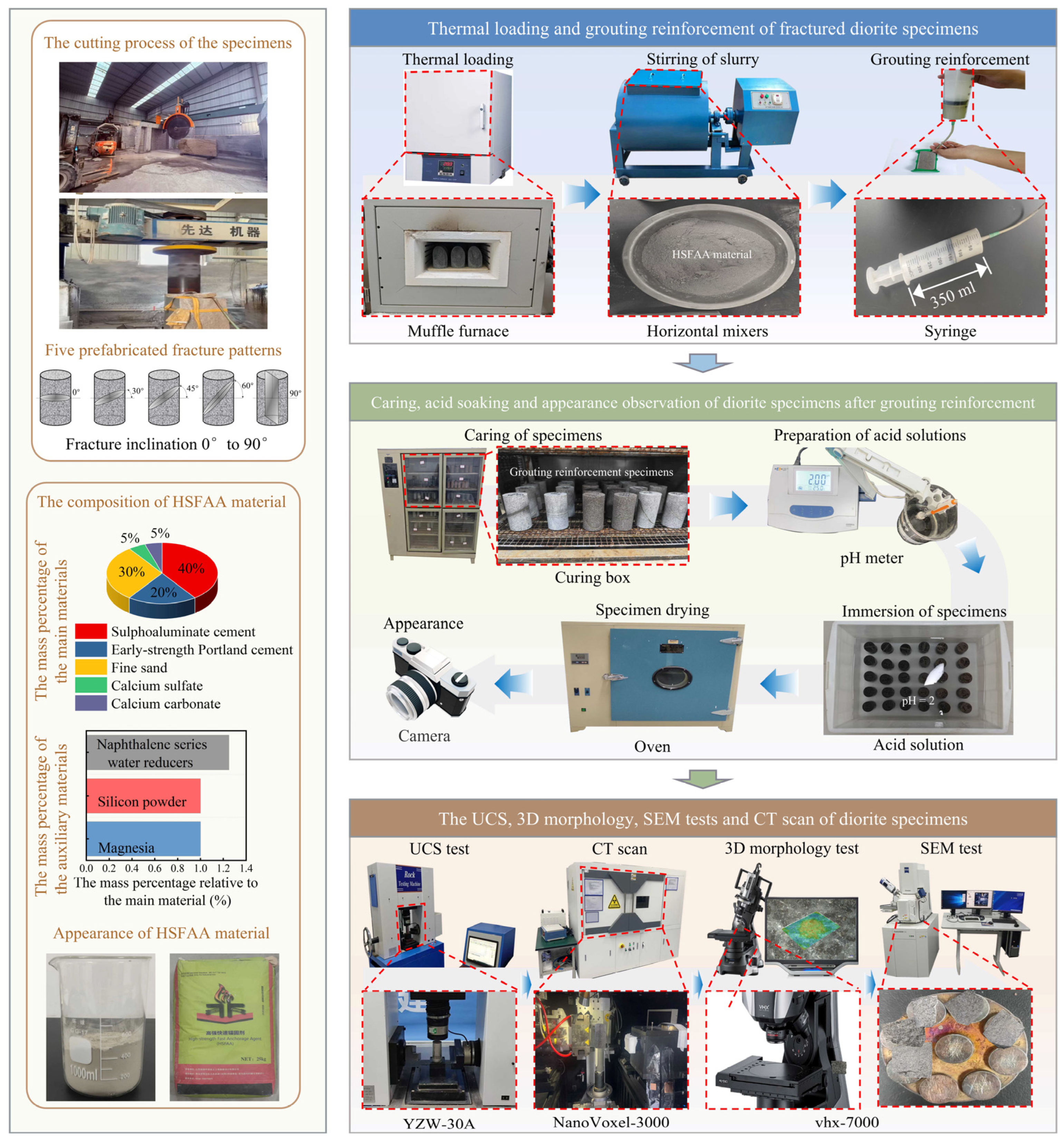
Figure 2 illustrates the schematic diagram of the grouting reinforcement methodology and experimental procedures for fractured diorite. The prefabricated fractured specimens were divided into two major groups (Group I and Group II), with each group containing six subgroups (A–F). Each subgroup contained three specimens for each of the five fracture angles (0°, 30°, 45°, 60°, and 90°). The subgroups were subjected to thermal treatments at 25 °C (ambient), 200 °C, 400 °C, 600 °C, 800 °C, and 1000 °C in a program-controlled chamber electric furnace. The heating rate was maintained at 5 °C/min until reaching target temperatures, followed by a 5-h isothermal holding period. The specimens were then cooled to room temperature at a rate of 3 °C/min to minimize thermal shock-induced microcrack propagation [33]. The temperature control accuracy was ±2 °C.
After thermal treatment, all specimens were grouted with HSFAA, a cement-based material validated for use in fractured rock masses, known for its micro-expansion, rapid hardening, and superior fluidity. HSFAA is composed of 40% calcium sulfoaluminate cement, 30% early-strength silicate cement, 20% fine sand, 5% gypsum, and 5% calcite, with additives including 1.25% naphthalene water-reducing agent, 1% magnesium oxide, and 1% silica micro-powder by weight of the main materials. The naphthalene agent enhances dispersion and reduces water usage, improving rheological properties. Magnesium oxide promotes early swelling and strength development, while silica micro-powder fills inter-particle voids, retains water, and supports secondary hydration by participating in volcanic ash reactions. As a result, HSFAA exhibits rapid strength gain, excellent fluidity, and volumetric stability. Its detailed composition, fluidity, setting time, and mechanical properties are further elaborated in Zhang et al. [28]. Table 1 presents the chemical composition of the HSFAA material. Grouting was performed using a 350 mL syringe with a piston advancement speed of 1.0 ± 0.1 mm/s to ensure uniformity and precise control of grout injection. During this process, the grouting pressure was approximately 150 kPa. An intermittent grouting strategy was employed to ensure thorough distribution within the fractures: 10 mL of grout was injected successively, followed by a 30-s pause to allow initial penetration. To confirm the complete filling of the fractures, the weight of the specimens was measured before and after grouting. Additionally, when the grout exuded from the opposite end of the specimen, it was collected in a graduated cylinder to measure the volume. The amount of grout collected was compared with the decrease in grout volume in the syringe. Injection was stopped when the volume of collected grout and the reduction in the syringe volume were approximately equal. This method ensures that the grout effectively fills the fractures without causing excessive pressure buildup. Specimens were then cured under standard conditions (20 ± 2 °C, ≥95% relative humidity) for 28 days.
The cured specimens in Group I were photographed to analyze surface morphology, oven-dried at 45 °C, and subjected to UCS testing using a hydraulic press (Model YZW-30A). For the UCS test, the specimens were placed between two parallel steel loading plates to ensure uniform load distribution. A displacement-controlled loading method was applied at a rate of 0.25 mm/min until specimen failure. The specimens in Group II underwent simulation of acidic environments: immersion in a 0.01 mol/L (pH = 2) hydrochloric acid solution for 30 days, with weekly solution renewal to maintain concentration stability. Post-immersion specimens were dried at 45 °C to avoid hydration product decomposition [34] before UCS testing using the same procedure as Group I, with displacement-controlled loading at a rate of 0.25 mm/min [35]. All specimens were wrapped in plastic film prior to testing to prevent fragment dispersion.
After the UCS test, six specimens with a 90° inclination angle, which had undergone the full process of “thermal treatment-grouting reinforcement-acid immersion” at 25 °C, 400 °C, 600 °C, 800 °C, and 1000 °C, were selected and scanned using a NanoVoxel-3000 CT system. This angle was selected because it allows for a clear observation of the failure mode and provides insight into how thermal and chemical treatments affect the material’s structural integrity. Additionally, considering the high cost of CT scanning, the 90° angle was chosen as a representative orientation that balances both effective imaging and cost efficiency. The spatial resolution of the CT scans was 23.9 μm/pixel. Steps including threshold segmentation, pore-crack extraction and 3D reconstruction were performed to quantify the internal structure of the grout-reinforced specimens and to assess the effect of the coupling temperature on their integrity. Specifically, the threshold segmentation procedure involved using Avizo 3D 2022 software to process the raw CT data, starting with an initial thresholding step based on grayscale intensity to distinguish cracks and pores from the surrounding matrix. This was followed by manual refinement to ensure accuracy, employing a consistent global threshold value determined from the 25 °C specimen and applied uniformly across all temperature groups (25 °C, 400 °C, 600 °C, 800 °C, and 1000 °C) to maintain consistency. Additionally, rock fragments from the mid-section of six specimens with an inclination angle of 90° (three specimens that underwent only the “thermal treatment-grouting reinforcement” process and three specimens that underwent the “thermal treatment-grouting reinforcement-acid immersion” process at 25 °C, 400 °C, and 800 °C, respectively) were selected for further examination. SEM (model GeminiSEM 300: Zeiss, Oberkochen, Germany) and surface 3D morphology (model vhx-7000 : Keyence, Osaka, Japan) scanning tests were performed on these fragments.

3. Results and Analyses

3.1. The Change of Apparent Color

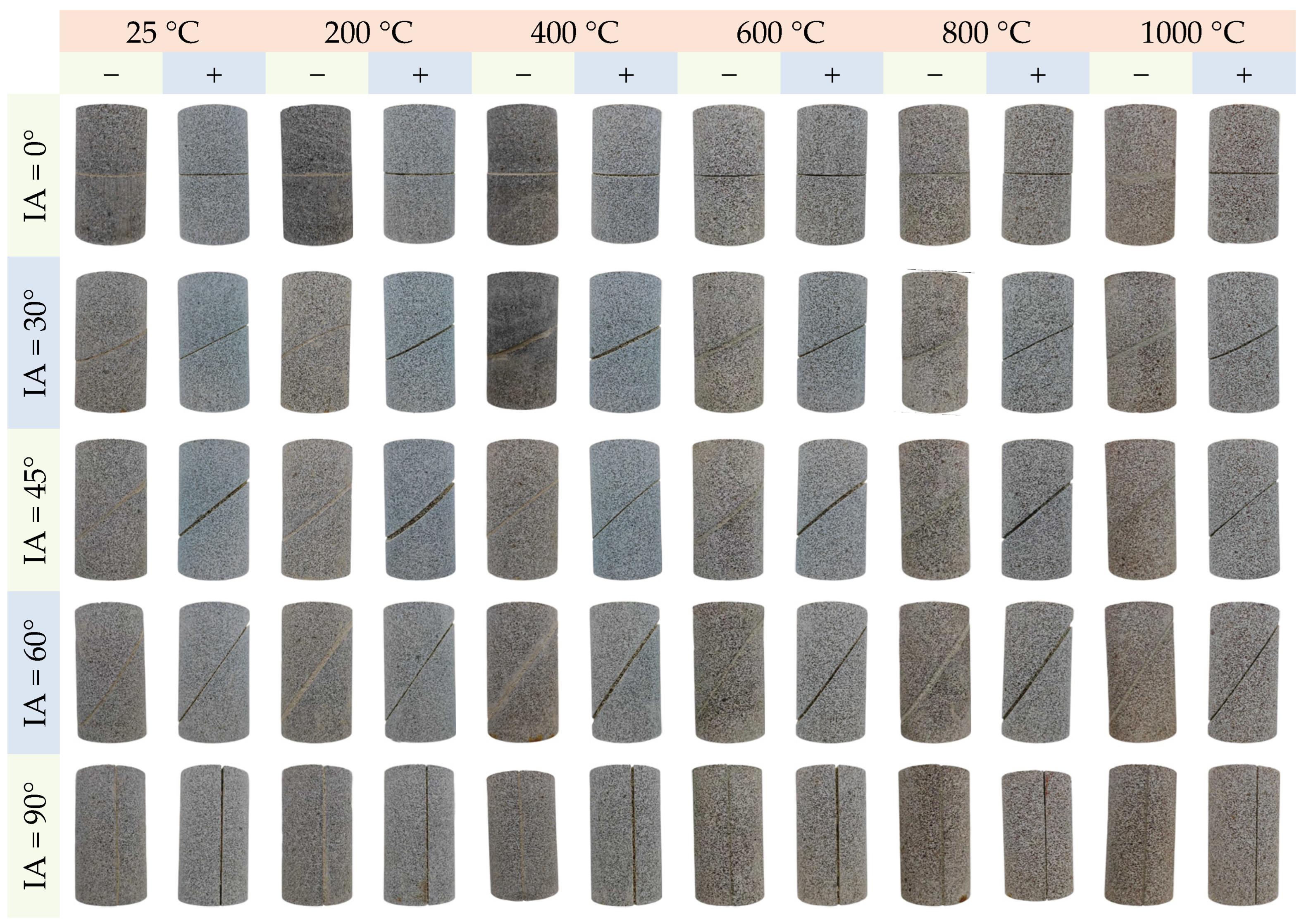
Figure 3 illustrates the surface color variations of grout-reinforced diorite specimens subjected to two distinct treatment protocols: “thermal treatment-grouting reinforcement” (denoted by “−”) and “thermal treatment-grouting reinforcement-acid immersion” (denoted by “+”). The symbol “IA” represents the inclination angle of the prefabricated fractures. The change in color is an important indicator of mineral phase transitions and structural changes, which can be used for the prediction or evaluation of the material’s response to thermal and chemical stresses. As shown in Figure 3, control specimens that were not subjected to thermal treatment (25 °C ambient) exhibited a natural gray-black coloration, primarily attributed to the inherent presence of dark minerals such as biotite and ferro-tschermakite in the diorite matrix. As thermal treatment temperature increased, the specimen surfaces gradually transitioned to brown tones. Notably, when temperatures exceeded the 600 °C threshold, phase reconstruction and oxidation reactions of biotite became dominant, intensifying surface browning [36]. Concurrently, high temperatures triggered phase transitions and pyrolysis of other minerals, including the α-β quartz transformation at 573 °C [37] and the melting-decomposition cascade reaction of feldspar minerals near 500 °C [38]. Acid immersion induced significant morphological alterations: specimens exhibited overall whitening accompanied by severe chemical erosion at the edges of HSFAA material. The acidic corrosion, superimposed on thermally weakened substrates, resulted in a “thermo-acid” composite damage effect that accelerated mineral dissolution and structural transformation. H+ ions permeated through thermally induced pores into the rock matrix. This facilitated continuous leaching of soluble aluminosilicate complexes into the solution. Concurrently, residual insoluble mineral frameworks (e.g., quartz residues) underwent color deactivation due to surface structural modifications [39]. This mineralogical “decoloration-reconstruction” process, along with collapse and reorganization of microporous structures, progressively stripped the original mineral-derived coloration, ultimately yielding a whitened appearance dominated by insoluble mineral residues. Such color changes are indicative of ongoing mineralogical degradation and provide valuable insights into the material’s stability and durability, making it a useful tool for evaluating the integrity of rocks exposed to extreme conditions.

3.2. Mechanical Test Results

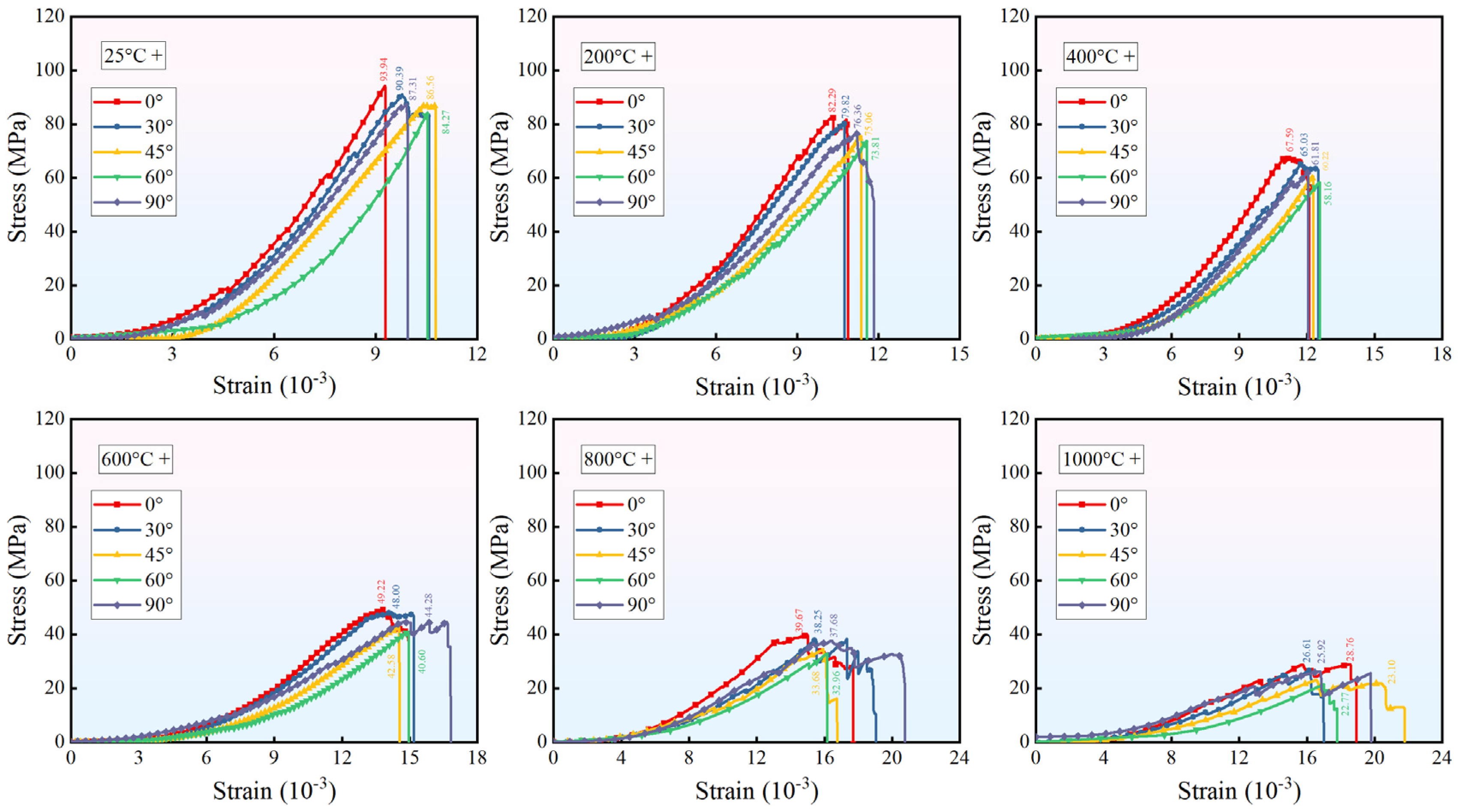
Figure 4 and Figure 5 present the stress–strain response characteristics of grout-reinforced diorite specimens under the two treatment protocols: “thermal treatment-grouting reinforcement” and “thermal treatment-grouting reinforcement-acid immersion”, respectively. Under identical thermal treatment conditions, the peak strength of specimens exhibited a significant attenuation trend as the prefabricated fracture angle increased from 0° to 60°. The enlarged fracture angle promoted stress concentration toward the fracture planes under axial loading, thereby intensifying shear stress concentration effects [40]. This stress redistribution mechanism elevated the proportion of shear slip failure at the HSFAA–rock interface, making it the primary driver of strength degradation. In contrast, when the fracture angle reached 90°, the orientation aligned perpendicular to the applied axial stress field, allowing the load to be distributed more uniformly across the specimen cross-section. This perpendicular alignment minimized shear stress concentrations at the grout–rock interface, reducing the likelihood of interfacial slip and enhancing the effective transfer of compressive forces through the intact axial structure. Consequently, the stress concentrations that typically weaken the interface were significantly alleviated, preserving the mechanical integrity of the grout-reinforced system. Notably, increasing thermal treatment temperature at constant fracture angles not only induced progressive strength reduction but also extended the compaction stage duration. Specimens subjected to thermal damage above 600 °C demonstrated pronounced ductile characteristics near peak stress, which was manifested as smooth transition zones in stress–strain curves. This behavior results from mineral phase transitions (e.g., feldspar melting, biotite dehydroxylation) and thermal expansion mismatch-induced microcrack network propagation [41]. Together, these factors degraded overall stiffness and strength. Acid exposure further reduced the initial linear slope of stress–strain curves. Particularly for 800 °C-treated specimens with coupled acid corrosion, the post-peak stage displayed complex stress decline features, characterized by decreased stress drop rates and increased fluctuations in the residual strength plateau. High-concentration H+ ions infiltrated specimens through prefabricated fractures and thermally induced microcracks, resulting in the dissolution of HSFAA hydration products (e.g., C-S-H gels, ettringite (AFt), etc.). This process drastically weakened interfacial bonding strength and diminished shear resistance along fracture walls. Concurrently, acidic solutions accelerated the expansion and interconnection of pre-existing thermal cracks within diorite, further compromising the mechanical integrity of specimens.
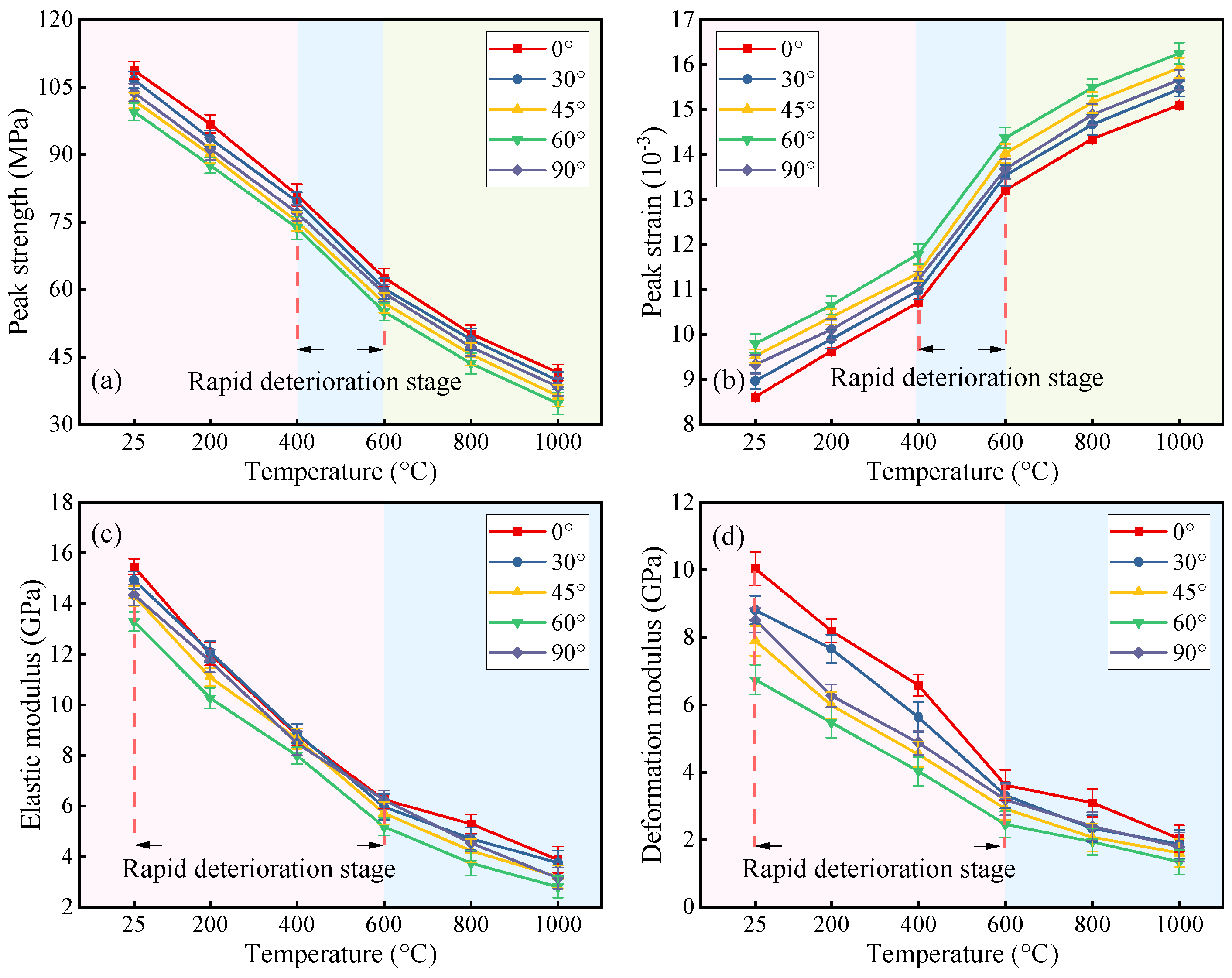
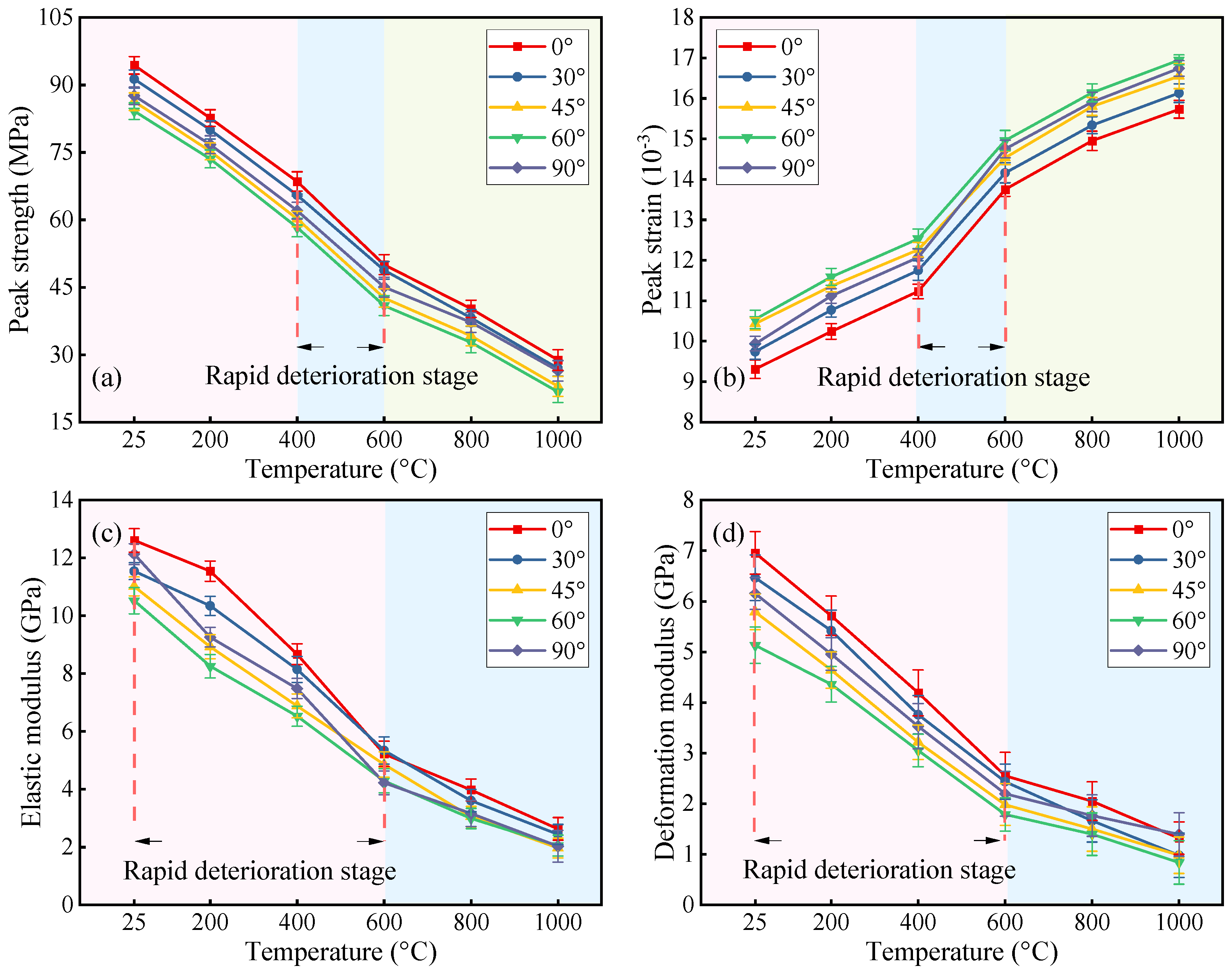
Figure 6 and Figure 7 display the variations in mechanical parameters extracted from Figure 4 and Figure 5, respectively. The elastic modulus is defined as the ratio of stress to strain in the maximum linear segment before the peak. The quantification of other parameters follows established methodologies from previous studies [42]. Under identical prefabricated fracture angles, gradient increases in thermal treatment temperature significantly degraded specimen strength and stiffness while enhancing deformation capacity. Specifically, peak strength, elastic modulus, and deformation modulus exhibited marked reductions, accompanied by progressive increases in peak strain. For specimens with a 0° angle, exposure to 1000 °C resulted in reductions of 62.82%, 74.89%, and 79.75% in peak strength, elastic modulus, and deformation modulus, respectively, compared to the 25 °C control group, while peak strain increased by 75.38%. At constant temperatures, increasing the fracture angles from 0° to 60° (excluding the specimens with a 90° angle, which showed localized strength recovery due to preserved axial integrity) led to synchronized deterioration of strength and stiffness parameters. Further exposure to hydrochloric acid exacerbated these trends through permeation–dissolution mechanisms that corroded HSFAA materials and inherent diorite minerals, critically reducing cementation strength and mineral skeleton stability. For instance, 0°-angled specimens subjected to 1000 °C thermal treatment coupled with acid corrosion exhibited reductions of 69.46%, 79.15%, and 81.04% in peak strength, elastic modulus, and deformation modulus, respectively, relative to the 25 °C control group, alongside a 68.96% increase in peak strain. This dual effect of strength–stiffness synergistic deterioration and ductile deformation enhancement reflects chemical corrosion’s catalytic role in expanding thermally induced microcrack networks and reshaping material constitutive relationships.
Notably, both treatment protocols induced accelerated degradation of peak strength and peak strain within the 400–600 °C temperature range, while the elastic modulus and deformation modulus demonstrated heightened temperature sensitivity from 25 °C to 600 °C, where the most rapid deterioration occurred. Specifically, the temperature effects on diorite specimens subjected to grouting reinforcement led to progressive failure. As the temperature increases, the mineral particles in the diorite expand unevenly due to thermal stress. When the temperature reaches the range of 400 °C to 600 °C, the thermal stress exceeds the rock’s tensile strength, resulting in the rapid formation of microcracks, which connect to form macrocracks, thereby compromising the integrity of the rock. Concurrently, mineral phase transitions occur in this temperature range, and the associated volume changes further exacerbate the structural damage. These combined effects cause the peak strength and peak strain to change rapidly. As the temperature rises further, the “damage potential” of the grouted diorite specimens is largely released. While the cracks may continue to slightly expand and residual minerals undergo minor alterations, the degree of new damage is significantly reduced compared to the earlier stage of “intense deterioration.”
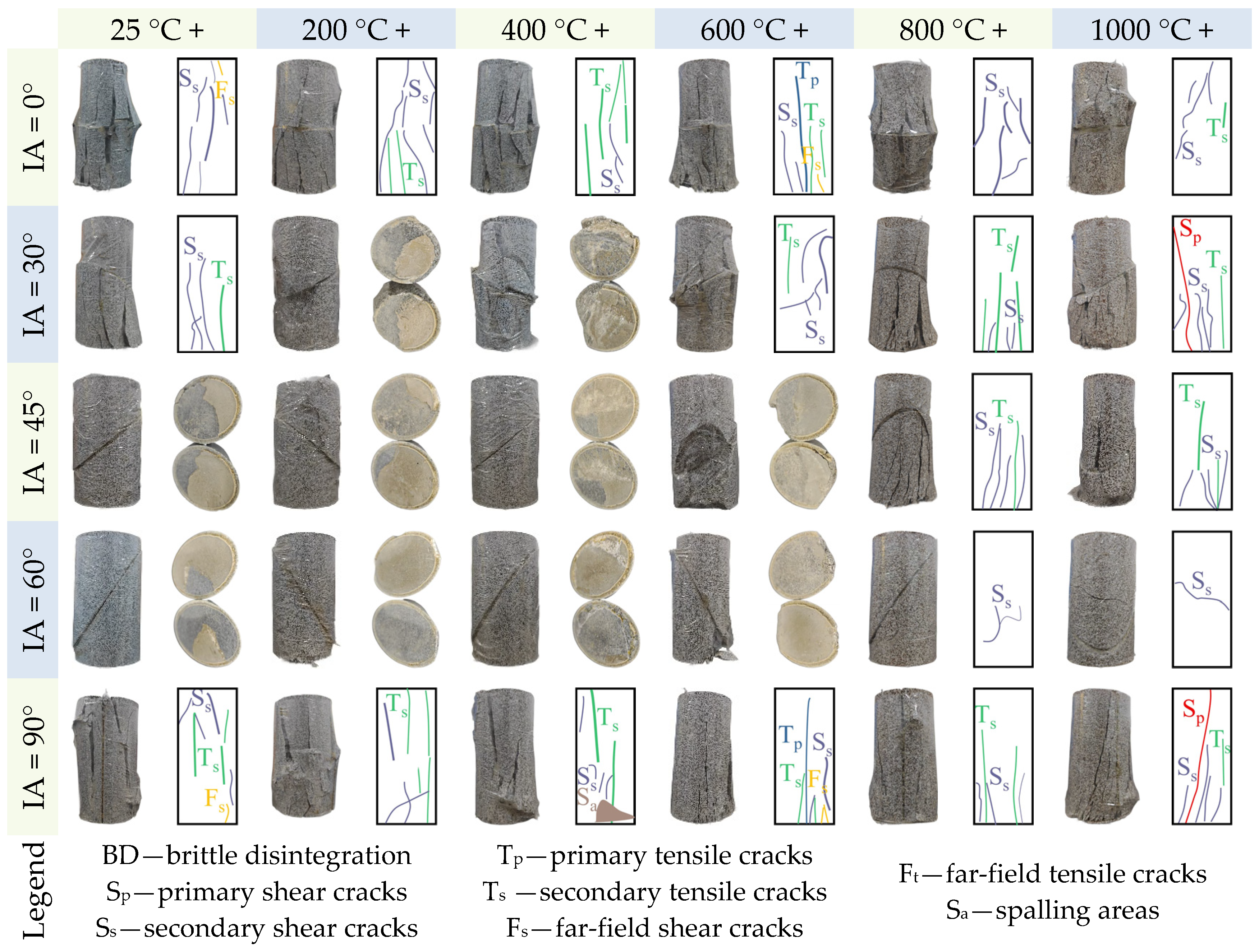
Figure 8 and Figure 9 present the failure modes of representative specimens subjected to “thermal treatment-grouting reinforcement” and “thermal treatment-grouting reinforcement-acid immersion” protocols after UCS tests, respectively. Based on an established crack classification system [43], surface cracks are categorized into primary shear cracks (Sp), secondary shear cracks (Ss), primary tensile cracks (Tp), secondary tensile cracks (Ts), far-field shear cracks (Fs), far-field tensile cracks (Ft), and spalling areas (Sa). As shown in Figure 8, under the “thermal treatment-grouting reinforcement” protocol, some specimens—specifically the 0°-angled specimens at 25–600 °C and 90°-angled specimens at 25–200 °C—exhibited brittle disintegration (denoted as BD in figures) during compression (BD refers to the complete collapse of the specimen, such that no identifiable cracks remain on the surface). This behavior is attributed to thermal treatment, which induces mineral phase transitions, decomposition, and microcrack propagation in diorite, but fails to fully suppress residual brittleness. Consequently, this led to instantaneous penetrating-crack propagation in stress-concentrated zones. In contrast, acid-immersed specimens (Figure 9) developed non-uniform corrosion notches at HSFAA edges under acidic attack. These notches initiated cracks that propagated slowly inward under axial loading, with gradual energy dissipation preventing brittle disintegration. Crack path analysis presented in Figure 8 revealed shear-dominated failures along prefabricated fractures for the 30°-angled specimens at 200 °C, the 45°-angled specimens at 25–400 °C, and the 60°-angled specimens at 25–600 °C. This mechanism arises from synergistic effects of shear stress concentration (amplified by increasing fracture angles) and insufficient shear resistance at HSFAA–rock interfaces. Acid corrosion exacerbated this trend as acidic solutions created complex corrosion morphologies, leading to a substantial reduction in interfacial bond strength and promoting slip-type failures along prefabricated fractures. Notably, the yellowing phenomenon observed on HSFAA fracture surfaces (as exemplified by the typical specimen in Figure 9, which shows a change in section color from gray-white to yellow-brown) directly reflected the dissolving effect of the hydrochloric acid solution on the hydration products, such as C-S-H gels, AFt, and portlandite. Furthermore, Ss cracks dominated uncorroded specimens, whereas the density of Ts crack increased significantly in acid-treated specimens. The shift from shear-dominated to tensile-shear hybrid failure modes is now more clearly presented, with an emphasis on the enhanced connectivity of thermally induced crack networks due to acid corrosion.

3.3. Results of SEM and 3D Topography Scans

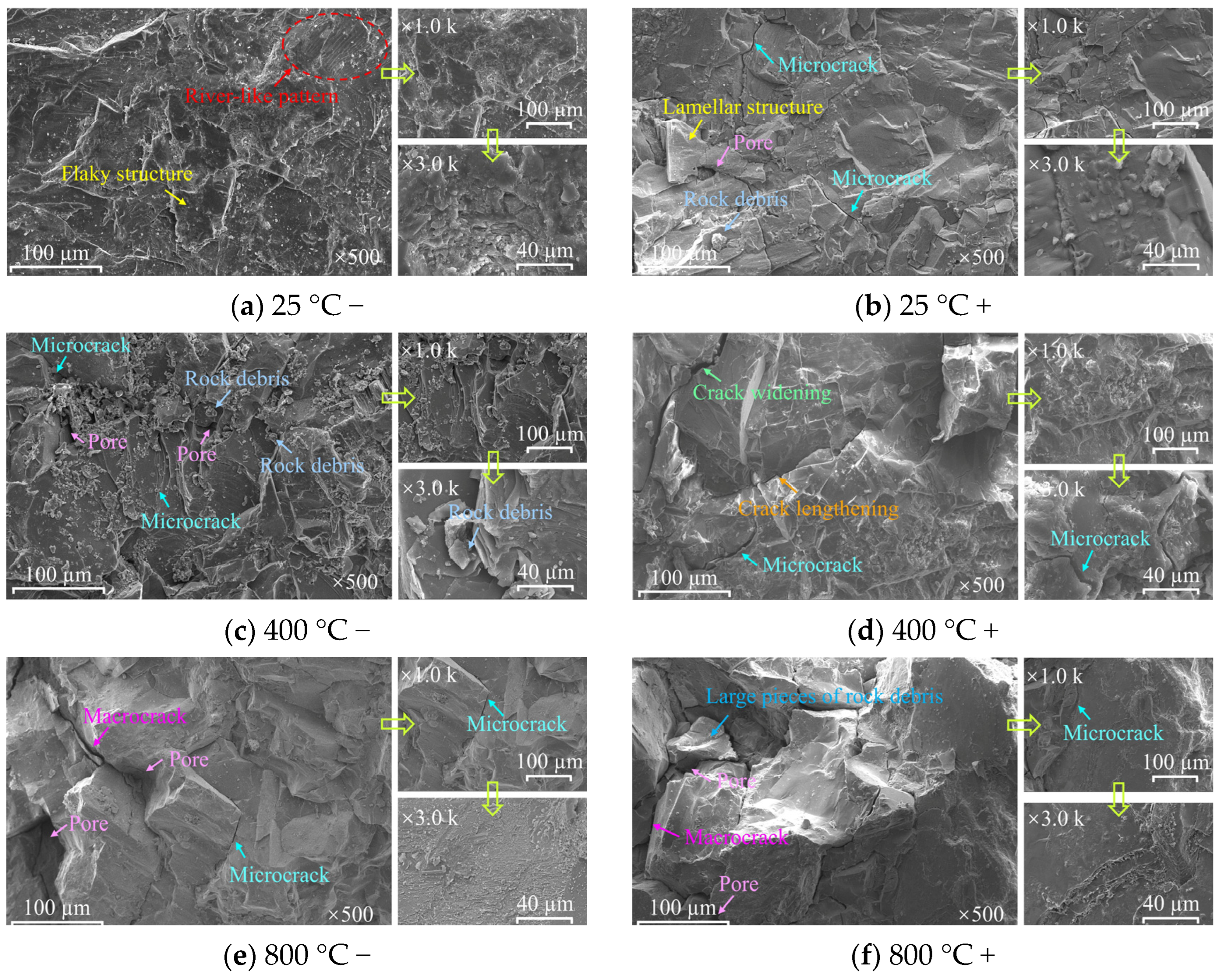
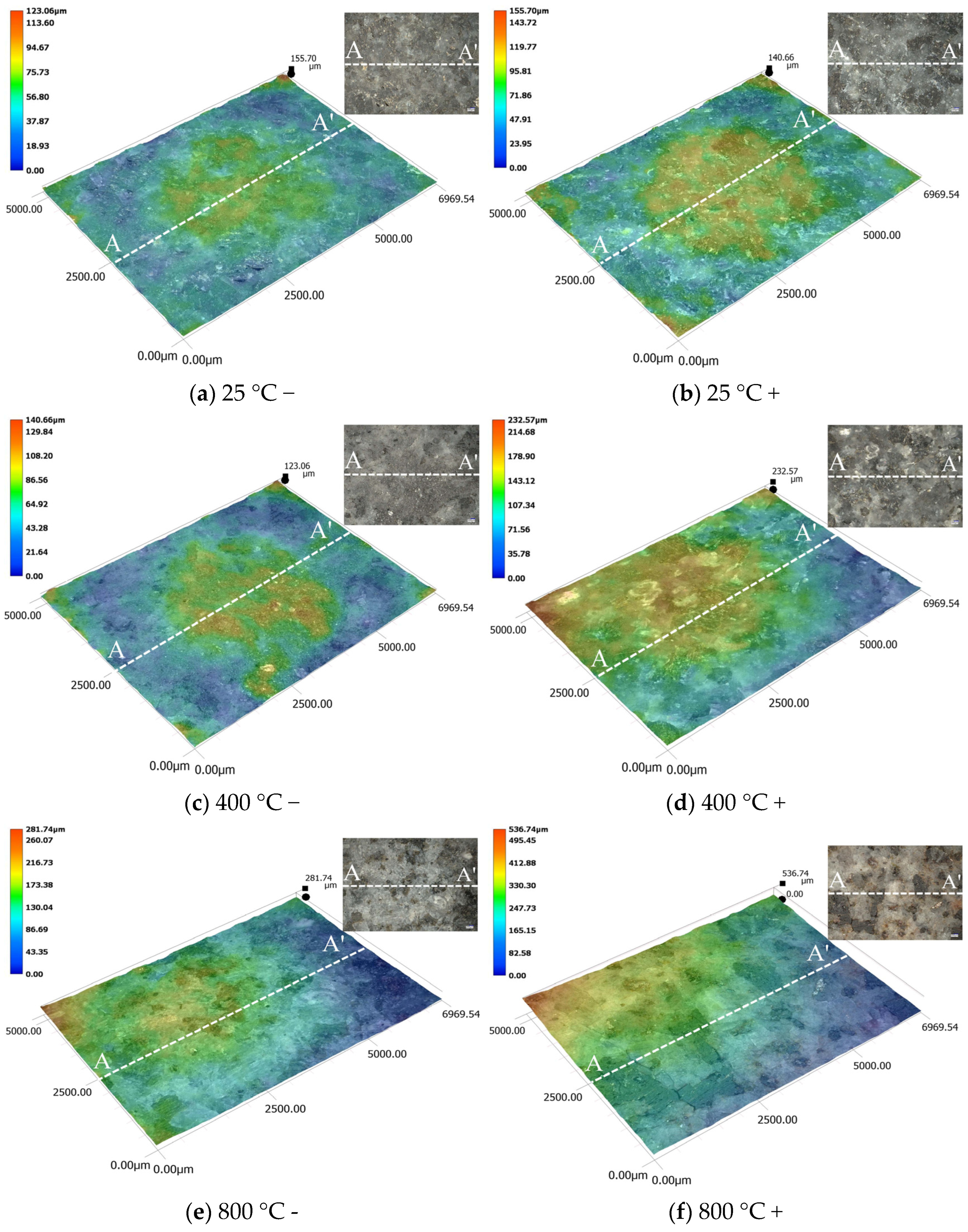
Figure 10 and Figure 11 present SEM images and 3D topographical scanning results of six selected diorite fragments under varying treatment protocols. Figure 10a and Figure 11a revealed that the fracture surface of diorite at 25 °C displayed river-like patterns and flaky structures, which are characteristic of typical brittle failure. The surface appeared relatively smooth and homogeneous, with no observable natural pores, fractures, or other damage features. This confirms the intact structure and stability of pristine diorite. In contrast, diorite coupled with hydrochloric acid at 25 °C (Figure 10b and Figure 11b) exhibited significant morphological alterations. Fractured surfaces were covered with rock debris and pores, accompanied by pervasive microcracks and markedly increased surface roughness. This transformation was attributed to H+-induced dissolution reactions with mineral components, leading to localized particle detachment and subsequent formation of corrosion pits and grooves. These features further evolved into microcracks under compressive loading. Thermal treatment at 400 °C (Figure 10c and Figure 11c) exacerbated surface degradation, characterized by increased debris density, pore proliferation, and localized protrusions caused by heterogeneous thermal expansion. Phase transitions within minerals generated microcracks preferentially along grain boundaries and weak zones. This established infiltration pathways for subsequent chemical attack. Acid immersion of 400 °C-treated specimens (Figure 10d and Figure 11d) intensified damage through synergistic thermo-chemical effects. H+ ions preferentially corroded thermally weakened regions, resulting in elongated/widened cracks, enlarged corrosion pits, and expanded damage zones. At 800 °C (Figure 10e and Figure 11e), surface deterioration escalated further, with microcracks coalescing into macrocracks and fractures exhibiting microstructural brittle-ductile hybrid characteristics, primarily due to localized ductile deformation around coalescing cracks amidst a predominantly brittle matrix. Once the quartz α-β phase transition threshold of 573 °C was surpassed, the specimen developed large-scale pores and fragmented regions, severely compromising structural integrity. However, at the macroscale, the rapid propagation of these macrocracks and the loss of interfacial bonding strength, as evidenced by the stress–strain curves in Figure 4 and Figure 5, resulted in predominantly brittle failure modes characterized by steep post-peak stress drops. Enhanced crack connectivity provided accelerated channels for acid penetration, hastening mechanical degradation. Under extreme 800 °C-acid coupling conditions (Figure 10f and Figure 11f), diorite surfaces displayed irreversible damage characterized by interconnected crack networks intertwined with corrosion traces, extensive mineral dissolution, exposed bulk debris, and densely distributed pits. These observations conclusively demonstrate the catastrophic impact of multi-field coupling on surface integrity.
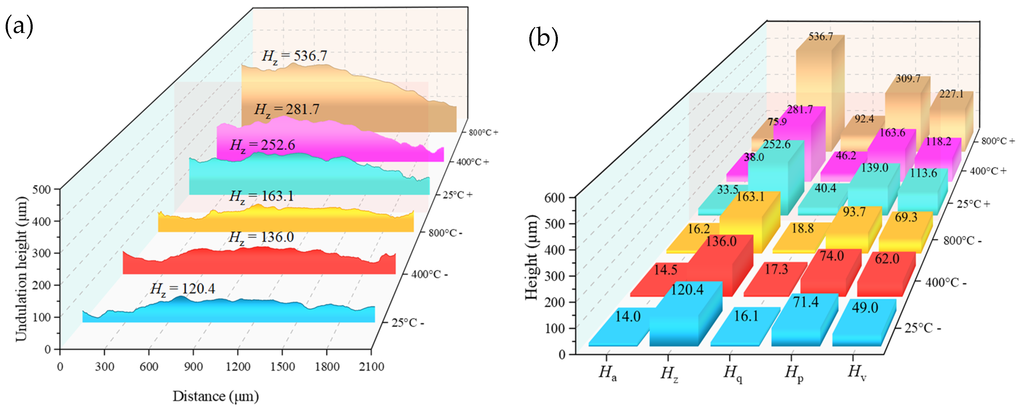
To quantitatively characterize the 3D topographical scanning results, surface height fluctuation profiles along baseline A-A’ were extracted from six diorite specimens illustrated in Figure 12. The quantitative results are presented in Figure 12a. Furthermore, Figure 12b illustrates the evolution of five key roughness parameters corresponding to this baseline: Ha (arithmetic mean height, which characterizes the absolute mean value of the surface microscopic undulation), Hp (maximum peak height, which reflects the maximum magnitude of the local convexity), Hv (maximum valley depth, which characterizes the maximum depth of the local concavity), and Hz (maximum height, i.e., the algebraic sum of Hp and Hv, which reflects the span of peaks and valleys of the surface morphology) and Hq (the root mean square height, which measures the root mean square dispersion of the surface roughness). As shown in Figure 12, diorite specimens at 25 °C exhibited smooth height fluctuation profiles with minimal parameter values, indicating homogeneous and stable microstructures. Following thermal treatment at 400 °C and 800 °C, height profiles progressively developed fluctuations, accompanied by systematic increases in all roughness parameters. This phenomenon originated from thermally induced mineral phase transitions and heterogeneous stress distribution. Localized stress concentration due to differential thermal expansion coefficients triggered microcrack initiation and particle protrusion, which significantly enhanced surface morphological complexity. Notably, specimens treated at 800 °C (exceeding the quartz α-β phase transition threshold at 573 °C) suffered irreversible structural damage. This resulted in the formation of abundant micropores and fragmented zones that severely degraded overall integrity. Compared to the 25 °C baseline, the Ha, Hz, Hq, Hp, and Hv increased by 16.26%, 35.47%, 16.75%, 31.38%, and 41.41%, respectively. Acid exposure drastically amplified surface roughness parameters. The thermo-acid coupling caused irreversible damage characterized by extensive mineral dissolution and densely distributed corrosion pits, severely compromising mechanical performance. After 800 °C-acid treatment, the Ha, Hz, Hq, Hp, and Hv surged by 345.91%, 345.91%, 473.39%, 334.00%, and 363.24%, respectively, relative to the 25 °C specimens.

3.4. CT Scan Results

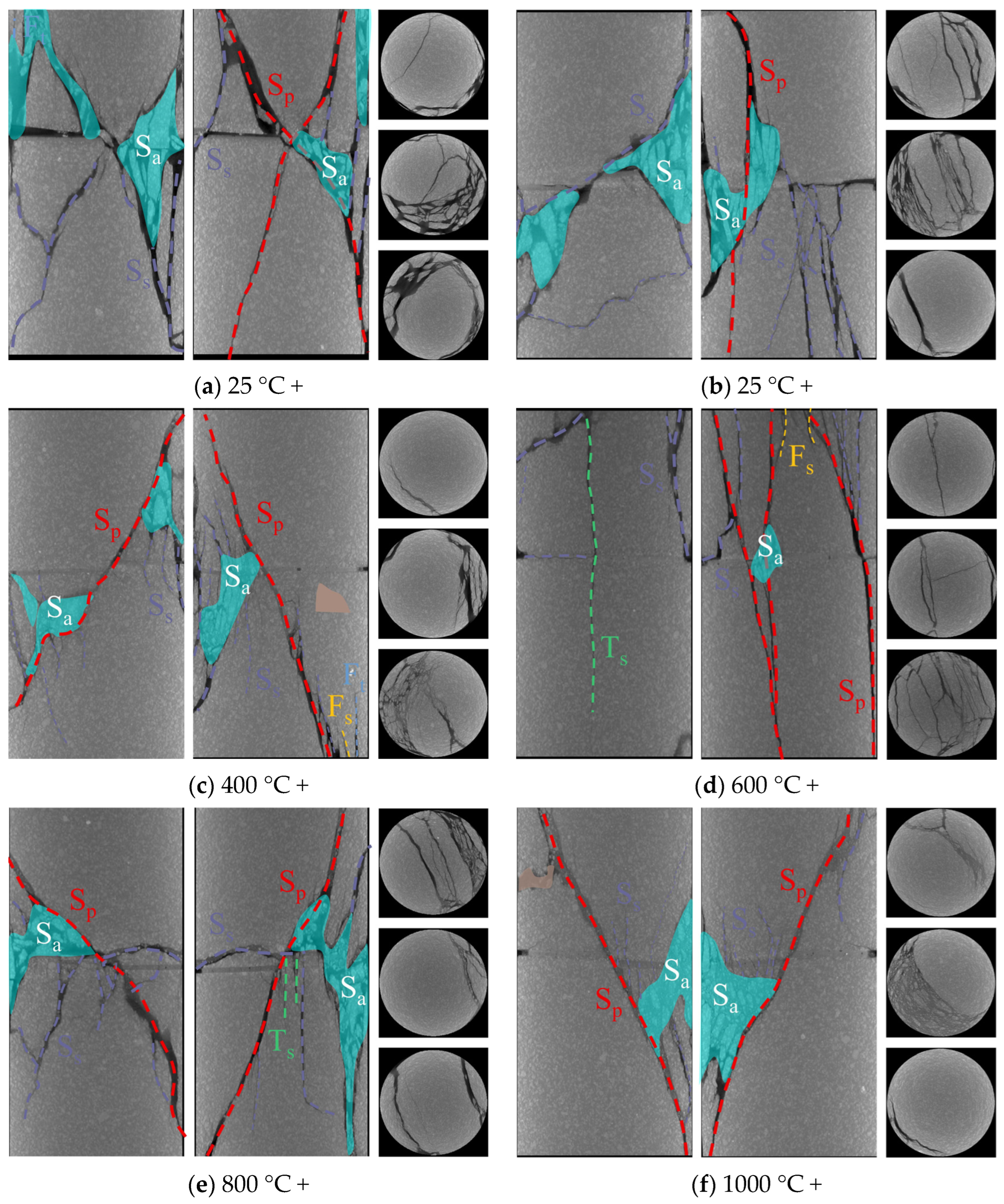
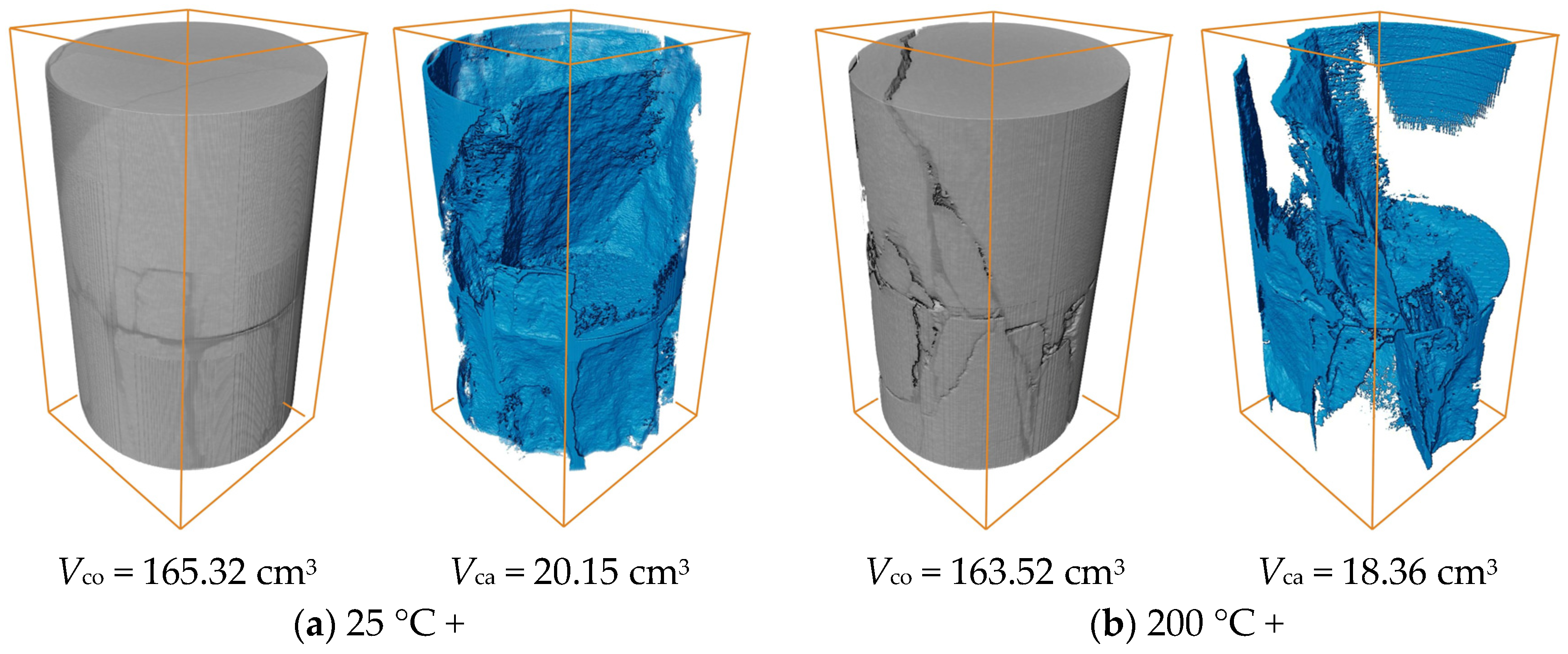
Figure 13 presents 2D CT scan images of six 90°-angled grout-reinforced diorite specimens subjected to the “thermal treatment-grouting reinforcement-acid immersion” protocol, where thermal treatment temperatures ranged from 25 °C to 1000 °C. Figure 14 displays 3D reconstructions and spatial crack distributions of these specimens, where Vto and Vca denote the calculated volumes of intact specimens and cracks, respectively. As shown in Figure 13, a strong correlation existed between the coupled thermal–acid treatment temperatures and the structural integrity. All six specimens exhibited shear-dominated failure modes characterized by Sp cracks accompanied by extensive Ss cracks. The widespread distribution of Ss cracks reflected stress release mechanisms in localized stress concentration zones during shear failure. Notably, these internal failure features differed significantly from surface crack patterns observed in Figure 9; however, they were consistent with findings by Zhang et al. [28]. This emphasizes the necessity of synergistic analysis that integrates surface crack propagation paths and internal fracture characteristics for accurate failure mode determination. Additionally, extensive Sa areas formed around prefabricated fractures, while Ts cracks were observed in 600 °C and 800 °C acid-treated specimens. Sa regions originated from HCl-induced chemical erosion of HSFAA grout, generating porous structures near fractures. These pores acted as structural weak points during loading, which promoted the initiation and propagation of microcracks. As illustrated in Figure 13, Vca progressively decreased from 20.15 cm3 to 13.17 cm3 as thermal treatment temperature increased from 25 °C to 1000 °C. This phenomenon was attributed to temperature-dependent mechanical evolution. Specimens at lower temperature exhibited pronounced brittleness, leading to localized disintegration and fragment separation, which created large crack voids. In contrast, higher-temperature treatments—particularly those beyond the threshold temperatures—enhanced ductility, resulting in gradual crack propagation under compression and post-fracture particle agglomeration. This explains the prevalence of finer cracks observed in high-temperature specimens via 2D imaging.

4. Discussion

4.1. Analysis of Damage Mechanism

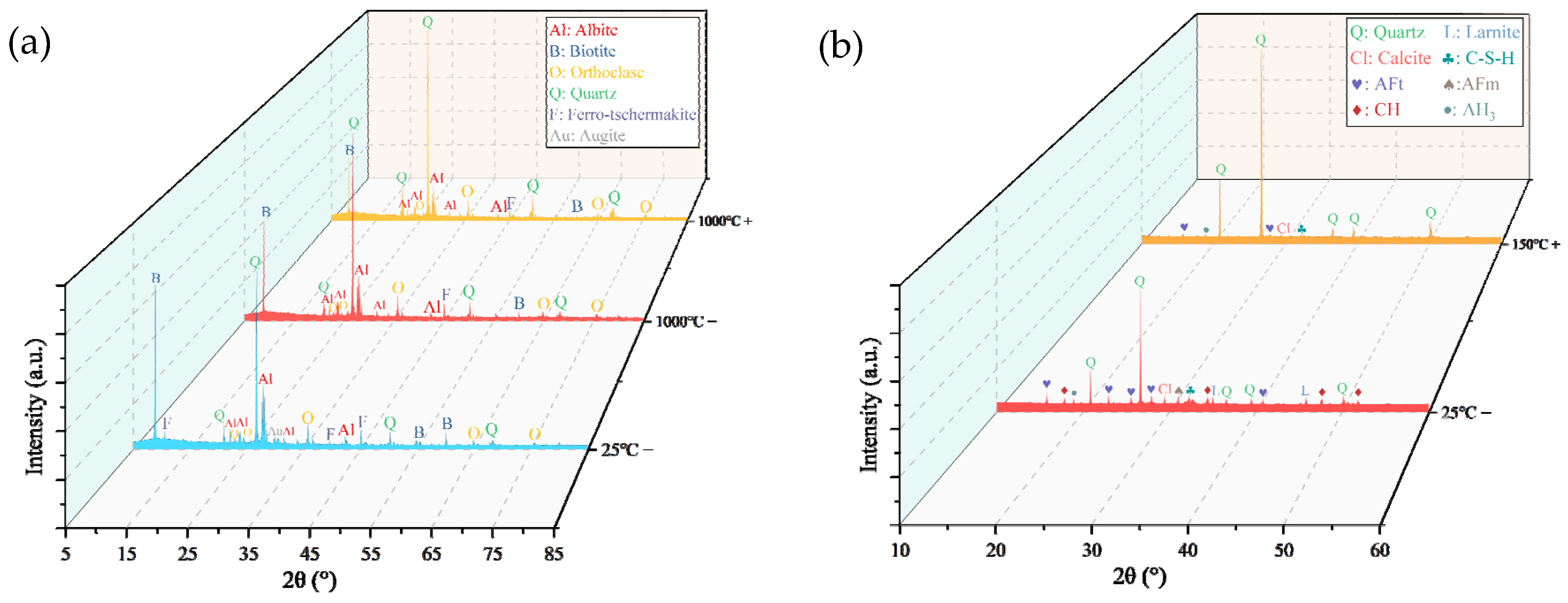
Fragments of diorite specimens treated at 25 °C and 1000 °C, along with a specimen subjected to a coupled treatment of 1000 °C and hydrochloric acid, were ground into powders for XRD analysis. Additionally, hardened slurry fragments of untreated HSFAA material (25 °C) and those immersed in hydrochloric acid for 30 days were collected for XRD analysis. The XRD results of these specimens are presented in Figure 15. It was observed that thermal treatment at 1000 °C significantly weakened the diffraction peaks of biotite, albite, and ferro-tschermakite in diorite, while the diffraction peaks of augite disappeared. In contrast, the diffraction peaks of quartz and orthoclase intensified due to an increase in their relative content. Further exposure to hydrochloric acid nearly eliminated the diffraction peaks of biotite, albite, and ferro-tschermakite, whereas the diffraction peaks of quartz and orthoclase exhibited enhanced intensity. The hydration products of HSFAA materials primarily consisted of C-S-H, AFt, monosulfate (AFm), calcium hydroxide (CH), and aluminium hydroxide (AH3). Their formation mechanisms are detailed in Zhang et al. [28]. After immersion in hydrochloric acid, most hydration products were dissolved by H+ ions. Only partial diffraction peaks of C-S-H, AFt, and AH3 remained in the specimens.
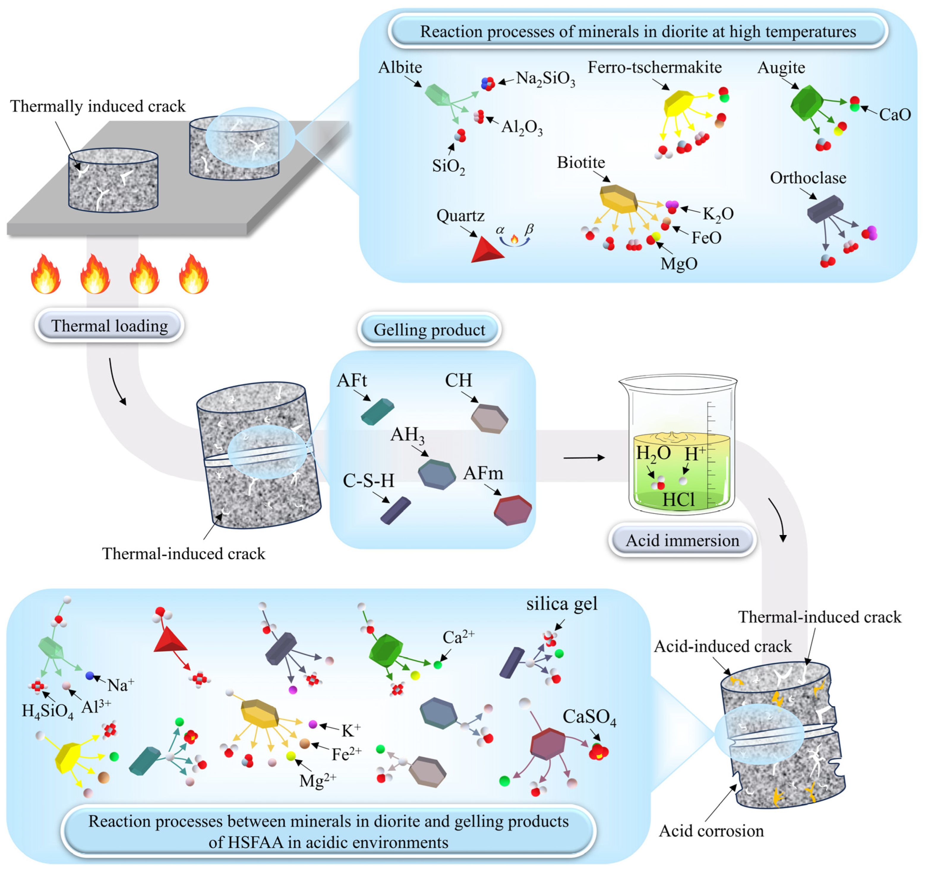
Under high-temperature conditions, inherent diorite minerals underwent complex physicochemical changes (Figure 16, Table 2). Quartz underwent α-β phase transition at 573 °C, causing thermal stress due to volume expansion. This process expanded existing microcracks and formed new thermally induced cracks. Concurrently, biotite and ferro-tschermakite experienced dehydration, melting, and thermal decomposition, which exacerbated material degradation. Post-grouting and acid immersion caused the dissolution of silicate minerals such as albite and orthoclase in diorite into acidic solutions. This process formed soluble salts and silicic acid gels (Figure 16, Table 3), leading to structural loosening and strength reduction. In addition, iron, magnesium, and aluminium-containing minerals like biotite and ferro-tschermakite in diorite might also undergo corrosive dissolution in acidic environments [44], further exacerbating the damage of diorite.
The hydration products in HSFAA grouting materials (excluding AH3, which remained stable only in alkaline environments) would decompose or dissolve in acidic environments, which would result in a reduction in the strength of the grouting material. The equations for these reactions are shown in Table 4. Two thin slices of HSFAA hardened slurry were polished and subjected to SEM tests in their pristine state and after acid immersion, respectively. The results are shown in Figure 17. The shedding of sand particles, as well as the formation of corrosion pores and microcracks on the surface of HSFAA after acid soaking could be observed. Simultaneously, the honeycomb-structured gel matrix and pompon-like gel product exhibited structural damage induced by acid corrosion. Furthermore, acidic solutions corroded the HSFAA–diorite interface, degrading the interfacial bonding properties. Specifically, thermally induced stresses generated under high-temperature conditions caused the initiation and propagation of microcracks within diorite. These microcracks provided penetration pathways for acidic solutions [44], through which H+ ions reacted with internal minerals, thereby dissolving cementitious phases and compromising their integrity. These reactions not only weakened the rock’s mechanical performance but also expanded microcrack dimensions and connectivity.
Where n is the water content participating in the hydration reaction; x and y are the CaO/SiO2 ratio and H2O/SiO2 ratio of C-S-H, respectively.

4.2. Fitting of Strength Parameters

Peak strength and elastic modulus, two critical mechanical parameters in engineering applications, were analyzed to clarify their temperature-dependent evolution. Polynomial fitting was applied to the peak strength and elastic modulus of specimens subjected to “thermal treatment-grouting reinforcement” (Figure 6) and “thermal treatment-grouting reinforcement-acid immersion” (Figure 7), with results shown in Figure 18 and Figure 19, respectively. The corresponding fitting equations are listed in Table 5 and Table 6. The fitting analysis revealed that both parameters exhibited significant temperature dependence. Specimens subjected to thermal–acid coupled treatment demonstrated accelerated mechanical degradation with increasing temperature. The peak strength of all fracture angles followed a quadratic polynomial decay law, with 0°-angled specimens exhibiting optimal strength retention. While the elastic modulus displayed similar trends to peak strength, it showed a higher sensitivity to acid corrosion. All fitting equations achieved R2 values exceeding 0.98, confirming the validity of quadratic polynomials in modeling the temperature-dependent evolution of mechanical parameters. Integrated CT scanning, SEM, and 3D topographical analyses clearly revealed that, under sustained thermo-acid coupling effects, the internal microcracks of grout-reinforced specimens exhibited significant propagation. Furthermore, the connectivity between distinct microcracks progressively increased, forming more complex crack networks. Simultaneously, mineral dissolution in acidic environments led to a notable rise in pore quantity, further enlargement of pore size, and a substantial increase in overall porosity. Additionally, decomposition of grout materials under acidic erosion exacerbated structural loosening of the grout-reinforced system. These pronounced microstructural changes inevitably triggered marked macroscopic mechanical degradation of the diorite grout-reinforced mass, specifically manifested as significant reductions in compressive strength and elastic modulus.

5. Conclusions

This study systematically revealed the failure mechanisms and damage evolution of grout-reinforced fractured diorite under thermal–acid coupling through multiscale characterization. It elucidated the effects of temperature gradients and prefabricated fracture angles on the mechanical properties and microstructural responses. The main conclusions are as follows:
(1)
When thermal treatment exceeded 600 °C, phase reconstruction and oxidation reactions of minerals like biotite transformed surfaces from gray-black to brown. Acid immersion led to whitening and severe corrosion at HSFAA edges. The “thermal–acid” coupling accelerated mineral dissolution and structural transformation, resulting in a whitening appearance dominated by insoluble mineral residues.
(2)
Increasing fracture angles (0–60°) exacerbated interfacial shear slip and reduced peak strength by up to 69.46% under thermal–acid coupling. Specimens with 90° angles retained higher strength. High temperatures (>600 °C) degraded stiffness and enhanced ductility, while acid corrosion further weakened interfaces and skeletons, amplifying ductile deformation.
(3)
Specimens exposed to uncoupled acid solutions at lower temperatures (25–600 °C) exhibited high brittleness, and some specimens disintegrated under uniaxial compression. Shear-dominated failures along prefabricated fractures prevailed with increasing angles. Acid corrosion suppressed brittle disintegration by forming non-uniform notches that enabled gradual energy release, promoting shear slip along fractures. Acidic environments significantly increased Ts crack density and shifted failure modes from shear-dominant to tensile-shear hybrid patterns.
(4)
3D CT showed a reduction in Vca with increasing heat treatment temperature, indicating a transition from macro-scale crack propagation to micro-scale coalescence. Acid corrosion further reduced Vca by 34.64% at 1000 °C. SEM revealed surface roughness increase, microcracks, and crushed rock chips under acid treatment. Acid preferentially dissolved active mineral components in diorite, while hydration products of HSFAA decomposed significantly.
In summary, this study provides valuable insights into the synergistic degradation mechanisms of grout-reinforced fractured rocks under thermal–acid coupling. The findings have important implications for the design and maintenance of underground structures in regions exposed to high temperatures and acidic environments. However, future research could focus on statistical analysis to further refine the results, increase confidence in the findings, and better guide engineering applications.

Author Contributions

Y.C.: Data curation, Investigation, Methodology, Writing—original draft. H.Z.: Writing—review & editing, Investigation, Supervision. T.L.: Project administration, Resources. Z.Y.: Supervision, Conceptualization, Funding acquisition. Y.Z.: Data curation, Validation. X.L.: Supervision, Resources. All authors have read and agreed to the published version of the manuscript.

Funding

The study is supported by the National Natural Science Foundation of China (42177153, 42372327, 42277139) and the Fundamental Research Funds for the Central Universities (202461071).

Data Availability Statement

Data will be made available on request.

Acknowledgments

The authors wish to express their sincere thanks to the National Natural Science Foundation of China and the Fundamental Research Funds for the Central Universities for support.

Conflicts of Interest

The authors declare no conflicts of interest.

References

  1. Tomar, M.S.; Khurana, S. Impact of passive fire protection on heat release rates in road tunnel fire: A review. Tunn. Undergr. Space Technol. 2019, 85, 149–159. [Google Scholar] [CrossRef]
  2. Zhang, H.; Liu, T.; Cui, Y.; Wang, W.; Yang, X.; Huang, X. Strength deterioration and damage mechanism of grout-reinforced fractured sandstone under the coupled effects of acidic erosion and freeze-thaw cycles. Constr. Build. Mater. 2024, 443, 137761. [Google Scholar] [CrossRef]
  3. Ma, S.J.; Ma, D.P. Grouting Material for Broken Surrounding Rock and its Mechanical Properties of Grouting Reinforcement. Geotech. Geol. Eng. 2021, 39, 3785–3793. [Google Scholar] [CrossRef]
  4. Huang, Z.; Zeng, W.; Gu, Q.; Wu, Y.; Zhong, W.; Zhao, K. Investigations of variations in physical and mechanical properties of granite, sandstone, and marble after temperature and acid solution treatments. Constr. Build. Mater. 2021, 307, 124943. [Google Scholar] [CrossRef]
  5. Zhang, J.P.; Liu, L.M.; Li, Y. Mechanism and experiment of self-stress grouting reinforcement for fractured rock mass of underground engineering. Tunn. Undergr. Space Technol. 2023, 131, 104826. [Google Scholar] [CrossRef]
  6. Mehdiabadi, N.; Abdi, Y.; Khanlari, G. An experimental investigation on the durability of clay-bearing rocks in different pH conditions. Geotech. Geol. Eng. 2023, 41, 2645–2663. [Google Scholar] [CrossRef]
  7. Wu, C.; Wang, S.Q.; Li, D.L.; Wang, X.K. NMR Experimental Study on Dynamic Process of Pore Structure and Damage Mechanism of Sandstones with Different Grain Sizes under Acid Erosion. Shock Vib. 2020, 2020, 3819507. [Google Scholar] [CrossRef]
  8. He, J.W.; Li, H.; Yang, W.; Lu, J.X.; Lu, Y.; Liu, T.; Shi, S.L. Experimental study on erosion mechanism and pore structure evolution of bituminous and anthracite coal under matrix acidification and its significance to coalbed methane recovery. Energy 2023, 283, 128485. [Google Scholar] [CrossRef]
  9. Feng, M.M.; Cao, X.X.; Yuan, K.S.; Zhang, M.W.; Li, Z.J. Influence of acidic environment on damage mechanism of sandstone under different climatic temperatures. Bull. Eng. Geol. Environ. 2022, 81, 452. [Google Scholar] [CrossRef]
  10. Yu, H.D.; Zhang, C.G.; Chen, H.H.; Canbulat, I.; Saydam, S. Effect of Anion Concentration in the Acidic Environment on Rock’s Mechanical Properties. Rock Mech. Rock Eng. 2025, 58, 4569–4583. [Google Scholar] [CrossRef]
  11. An, H.M.; Zeng, T.S.; Zhang, Z.H.; Liu, L. Experimental Study of the Rock Mechanism under Coupled High Temperatures and Dynamic Loads. Adv. Civ. Eng. 2020, 2020, 8866621. [Google Scholar] [CrossRef]
  12. Hu, J.J.; Xie, H.P.; Li, C.B.; Liu, G.K. Evolution mechanism of permeability of hot dry rock under coupled effect of thermal fatigue and seawater interaction during coastal geothermal development. Renew. Sustain. Energy Rev. 2024, 189, 114061. [Google Scholar] [CrossRef]
  13. Xie, H.P.; Lu, J.; Li, C.B.; Li, M.H.; Gao, M.Z. Experimental study on the mechanical and failure behaviors of deep rock subjected to true triaxial stress: A review. Int. J. Min. Sci. Technol. 2022, 32, 915–950. [Google Scholar] [CrossRef]
  14. Tian, H.; Mei, G.; Jiang, G.-S.; Qin, Y. High-Temperature Influence on Mechanical Properties of Diorite. Rock Mech. Rock Eng. 2017, 50, 1661–1666. [Google Scholar] [CrossRef]
  15. Li, M.; Mao, X.; Cao, L.; Pu, H.; Lu, A. Influence of heating rate on the dynamic mechanical performance of coal measure rocks. Int. J. Geomech. 2017, 17, 04017020. [Google Scholar] [CrossRef]
  16. Waqas, U.; Ahmed, M.F. Prediction Modeling for the Estimation of Dynamic Elastic Young’s Modulus of Thermally Treated Sedimentary Rocks Using Linear–Nonlinear Regression Analysis, Regularization, and ANFIS. Rock Mech. Rock Eng. 2020, 53, 5411–5428. [Google Scholar] [CrossRef]
  17. Zhang, H.; Liu, T.; Cui, Y.; Zheng, J.; Wang, W.; Li, Y. Experimental study on the deterioration mechanisms of physical and mechanical properties of red sandstone after thermal-acid coupling treatment. Constr. Build. Mater. 2024, 455, 139106. [Google Scholar] [CrossRef]
  18. Leroy, M.N.L.; Marius, F.W.; Francois, N. Experimental and Theoretical Investigations of Hard Rocks at High Temperature: Applications in Civil Engineering. Adv. Civ. Eng. 2021, 2021, 8893944. [Google Scholar] [CrossRef]
  19. Zhao, Z.; Liu, Z.; Pu, H.; Li, X. Effect of Thermal Treatment on Brazilian Tensile Strength of Granites with Different Grain Size Distributions. Rock Mech. Rock Eng. 2018, 51, 1293–1303. [Google Scholar] [CrossRef]
  20. Bao, H.; Xu, G.; Wang, Q.; Peng, Y.; Liu, J. Study on the deterioration mechanism of cement-based materials in acid water containing aggressive carbon dioxide. Constr. Build. Mater. 2020, 243, 118233. [Google Scholar] [CrossRef]
  21. Araghi, H.J.; Nikbin, I.; Reskati, S.R.; Rahmani, E.; Allahyari, H. An experimental investigation on the erosion resistance of concrete containing various PET particles percentages against sulfuric acid attack. Constr. Build. Mater. 2015, 77, 461–471. [Google Scholar] [CrossRef]
  22. Huang, X.; Pang, J.Y.; Zou, J.Q. Study on the Effect of Dry-Wet Cycles on Dynamic Mechanical Properties of Sandstone Under Sulfuric Acid Solution. Rock Mech. Rock Eng. 2022, 55, 1253–1269. [Google Scholar] [CrossRef]
  23. Huang, Z.; Zeng, W.; Wu, Y.; Li, S.J.; Gu, Q.X.; Zhao, K. Effects of temperature and acid solution on the physical and tensile mechanical properties of red sandstones. Environ. Sci. Pollut. Res. 2021, 28, 20608–20623. [Google Scholar] [CrossRef]
  24. Li, S.G.; Wu, Y.M.; Huo, R.K.; Song, Z.P.; Fujii, Y.; Shen, Y.J. Mechanical Properties of Acid-corroded Sandstone Under Uniaxial Compression. Rock Mech. Rock Eng. 2021, 54, 289–302. [Google Scholar] [CrossRef]
  25. Zhao, J.X.; Lu, C.H.; Deng, L.M.; Liu, G.C. Impacts of simulated acid solution on the disintegration and cation release of purple rock (mudstone) in Southwest China. Geomorphology 2018, 316, 35–43. [Google Scholar] [CrossRef]
  26. Shang, D.L.; Zhao, Z.H.; Dou, Z.H.; Yang, Q. Shear behaviors of granite fractures immersed in chemical solutions. Eng. Geol. 2020, 279, 105869. [Google Scholar] [CrossRef]
  27. Chen, W.H.; Yang, J.; Li, L.; Wang, H.C.; Huang, L.; Jia, Y.C.; Hu, Q.Y.; Jiang, X.W.; Tang, J.Z. Investigation of Mechanical Properties Evolution and Crack Initiation Mechanisms of Deep Carbonate Rocks Affected by Acid Erosion. Sustainability 2023, 15, 11807. [Google Scholar] [CrossRef]
  28. Zhang, H.; Wang, W.; Qiu, X.; Zheng, J.; Liu, T. Mechanical properties of fracture-grouted prefabricated sandstone after thermal-acid coupling treatment: An experimental study. Constr. Build. Mater. 2024, 411, 134552. [Google Scholar] [CrossRef]
  29. Wang, Z.Y.; Du, M.R.; Fang, H.Y.; Zhang, C.; Li, M.J.; Shi, M.S. Influence of different corrosion environments on mechanical properties of a roadbed rehabilitation polyurethane grouting material under uniaxial compression. Constr. Build. Mater. 2021, 301, 124092. [Google Scholar] [CrossRef]
  30. Manquehual, C.J.; Jakobsen, P.D.; Bruland, A. Corrosion Level of Rock Bolts Exposed to Aggressive Environments in Nordic Road Tunnels. Rock Mech. Rock Eng. 2021, 54, 5903–5920, Erratum in Rock Mech. Rock Eng. 2021, 54, 5921–5922. [Google Scholar] [CrossRef] [PubMed]
  31. Sun, Q.; Zhang, W.Q.; Pan, X.H.; Zhang, Y.L. The effect of heating/cooling cycles on chrominance, wave velocity, thermal conductivity and tensile strength of diorite. Environ. Earth Sci. 2019, 78, 403. [Google Scholar] [CrossRef]
  32. Corkum, A.G.; Asiri, Y.; El Naggar, H.; Kinakin, D. The Leeb Hardness Test for Rock: An Updated Methodology and UCS Correlation. Rock Mech. Rock Eng. 2018, 51, 665–675. [Google Scholar] [CrossRef]
  33. Sha, S.; Rong, G.; Chen, Z.H.; Li, B.W.; Zhang, Z.Y. Experimental Evaluation of Physical and Mechanical Properties of Geothermal Reservoir Rock after Different Cooling Treatments. Rock Mech. Rock Eng. 2020, 53, 4967–4991. [Google Scholar] [CrossRef]
  34. Mehta, P. Stability of ettringite on heating. J. Am. Ceram. Soc. 1972, 55, 55–57. [Google Scholar] [CrossRef]
  35. Zhang, H.; Liu, T.; Cui, Y.; Wang, W.; Qing, C. Experimental study on the performance of basalt fiber combined with cement-based material solidified shield waste mud under the coupled effects of acid corrosion and dry-wet cycles. Constr. Build. Mater. 2025, 463, 140110. [Google Scholar] [CrossRef]
  36. Brigatti, M.F.; Guggenheim, S. Mica crystal chemistry and the influence of pressure, temperature, and solid solution on atomistic models. Rev. Mineral. Geochem. 2002, 46, 1–97. [Google Scholar]
  37. Fukuhara, M.; Sampei, A. Effects on high-temperature-elastic properties on α-/β-quartz phase transition of fused quartz. J. Mater. Sci. Lett. 1999, 18, 751–753. [Google Scholar] [CrossRef]
  38. Vidana Pathiranagei, S.; Gratchev, I.; Kong, R. Engineering properties of four different rocks after heat treatment. Geomech. Geophys. Geo-Energy Geo-Resour. 2021, 7, 16. [Google Scholar] [CrossRef]
  39. Martyushev, D.A.; Govindarajan, S.K.; Li, Y.W.; Yang, Y.F. Experimental study of the influence of the content of calcite and dolomite in the rock on the efficiency of acid treatment. J. Pet. Sci. Eng. 2022, 208, 109770. [Google Scholar] [CrossRef]
  40. Yang, S.Q.; Jing, H.W.; Huang, Y.H.; Ranjith, P.G.; Jiao, Y.Y. Fracture mechanical behavior of red sandstone containing a single fissure and two parallel fissures after exposure to different high temperature treatments. J. Struct. Geol. 2014, 69, 245–264. [Google Scholar] [CrossRef]
  41. Li, M.; Wang, D.M.; Shao, Z.L. Experimental study on changes of pore structure and mechanical properties of sandstone after high-temperature treatment using nuclear magnetic resonance. Eng. Geol. 2020, 275, 105739. [Google Scholar] [CrossRef]
  42. Zhang, H.; Liu, T.; Cui, Y.; Wang, Z.; Wang, W.; Zheng, J. Compression and shear properties of OPC-MCA and basalt fiber cured shield waste mud after dry-wet cycles. Constr. Build. Mater. 2024, 426, 136153. [Google Scholar] [CrossRef]
  43. Zhang, H.G.; Liu, T.; Wang, W.H.; Cui, Y.X.; Wu, Y.K.; Qiu, X.Y. Effective curing of waste mud from slurry shield tunnels using OPC-MCA: Experimental investigations and microstructural analysis. Tunn. Undergr. Space Technol. 2025, 161, 106554. [Google Scholar] [CrossRef]
  44. Damion, T.; Chaunsali, P. Evaluating acid resistance of Portland cement, calcium aluminate cement, and calcium sulfoaluminate based cement using acid neutralisation. Cem. Concr. Res. 2022, 162, 107000. [Google Scholar] [CrossRef]
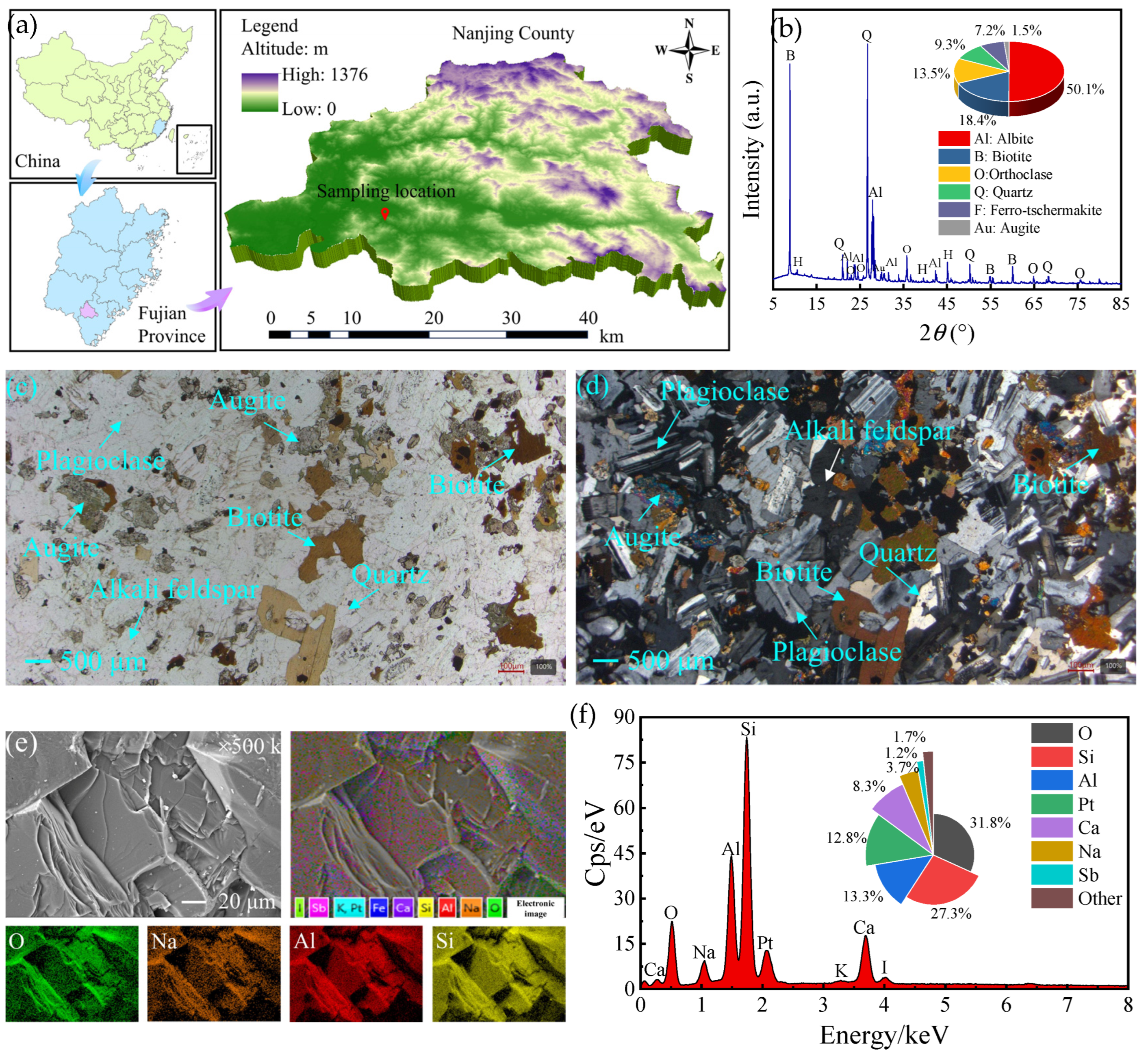
Figure 1. (a) Provenance information, (b) XRD spectra, (c) planar polarised light and (d) cross polarised light images, surface element (e) distribution and (f) content images of experimental diorite specimens.
Buildings 15 03547 g001
Figure 2. Grouting reinforcement methods and experimental procedures for fractured diorite.
Buildings 15 03547 g002
Figure 3. The surface color variations of grout-reinforced diorite specimens after different treatments.
Buildings 15 03547 g003
Figure 4. Stress–strain curves of grout-reinforced diorite specimens subjected to the “thermal treatment-grouting reinforcement” protocol.
Buildings 15 03547 g004
Figure 5. Stress–strain curves of grout-reinforced diorite specimens subjected to the “thermal treatment-grouting reinforcement-acid immersion” protocol.
Buildings 15 03547 g005
Figure 6. (a) Peak strength, (b) peak strain, (c) elastic modulus and (d) deformation modulus of grout-reinforced diorite specimens subjected to the “thermal treatment-grouting reinforcement” protocol.
Buildings 15 03547 g006
Figure 7. (a) Peak strength, (b) peak strain, (c) elastic modulus and (d) deformation modulus of grout-reinforced diorite specimens subjected to the “thermal treatment-grouting reinforcement-acid immersion” protocol.
Buildings 15 03547 g007
Figure 8. Failure modes of grout-reinforced diorite specimens subjected to the “thermal treatment-grouting reinforcement” protocol after UCS tests.
Buildings 15 03547 g008
Figure 9. Failure modes of grout-reinforced diorite specimens subjected to the “thermal treatment-grouting reinforcement-acid immersion” protocol after UCS tests.
Buildings 15 03547 g009
Figure 10. SEM images of six selected diorite fragment specimens.
Buildings 15 03547 g010
Figure 11. 3D morphology scanning results of six selected diorite fragment specimens.
Buildings 15 03547 g011
Figure 12. Variation of (a) undulation height profile along the baseline A-A’ and (b) roughness parameter of six selected diorite fragment specimens.
Buildings 15 03547 g012
Figure 13. 2D CT images of six selected grout-reinforced diorite specimens.
Buildings 15 03547 g013
Figure 14. 3D CT images of six selected grout-reinforced diorite specimens.
Buildings 15 03547 g014aBuildings 15 03547 g014b
Figure 15. XRD patterns of (a) diorite and (b) HSFAA hydration products.
Buildings 15 03547 g015
Figure 16. Damage mechanisms of grout-reinforced diorite specimens under the action of high temperature and acidic solution.
Buildings 15 03547 g016
Figure 17. SEM images of the surface of the hardened slurry of HSFAA material before and after acid immersion.
Buildings 15 03547 g017
Figure 18. Results of fitted curves of (a) peak strength and (b) elastic modulus of grout-reinforced diorite specimens subjected to the “thermal treatment-grouting reinforcement” protocol.
Buildings 15 03547 g018
Figure 19. Results of fitted curves of (a) peak strength and (b) elastic modulus of grout-reinforced diorite specimens subjected to the “thermal treatment-grouting reinforcement-acid immersion” protocol.
Buildings 15 03547 g019
Table 1. Chemical composition of HSFAA (wt%).
MaterialsSiO2CaO Al2O3SO3MgOFe2O3TiO2K2OP2O5Na2OLol
HSFAA36.8533.4614.406.671.781.580.650.290.110.103.03
Table 2. Reaction equations for the potential of minerals inherent in diorite in high temperature environments.
MineralsReaction Equations
Albite 2 NaAlSi 3 O 8 Na 2 SiO 3 + Al 2 O 3 + 5 SiO 2
Biotite 2 KFeMg 2 ( AlSi 3 O 10 ) ( OH ) 2 K 2 O + 2 FeO + 4 MgO + Al 2 O 3 + 6 SiO 2 + 2 H 2 O
Orthoclase 2 KAlSi 3 O 8 K 2 O + Al 2 O 3 + 6 SiO 2
Ferro-tschermakite Ca 2 Fe 3 Al 2 ( Si 6 Al 2 ) O 22 ( OH ) 2 2 CaO + 3 FeO + 2 Al 2 O 3   + 6 SiO 2 + H 2 O  
Quartz a · quartz 573 ° C β · quartz
Augite CaMgSi 2 O 6 CaO + MgO + 2 SiO 2
Table 3. Physicochemical reaction equations for minerals under thermal–acid coupling.
MineralsReaction Equations
Albite NaAlSi 3 O 8 + 4 H + + 4 H 2 O Na + + Al 3 + + 3 H 4 SiO 4
Biotite KFeMg 2 ( AlSi 3 O 10 ) ( OH ) 2 + 10 H + K + + Fe 2 + + 2 Mg 2 + + Al 3 + + 3 SiO 2 + 6 H 2 O
Orthoclase KAlSi 3 O 8 + 4 H + + 4 H 2 O K + + Al 3 + + 3 H 4 SiO 4
Ferro-tschermakite Ca 2 Fe 3 Al 2 ( Si 6 Al 2 ) O 22 ( OH ) 2 + 22 H + 2 Ca 2 + + 3 Fe 2 + + 4 Al 3 + + 6 H 4 SiO 4
Quartz SiO 2 + 2 H 2 O H 4 SiO 4   ( very   little )
Augite CaMgSi 2 O 6 + 4 H + + 2 H 2 O Ca 2 + + Mg 2 + + 2 H 4 SiO 4
Table 4. The reaction equations of hydration products of HSFAA materials in acidic environments.
Hydration ProductsReaction Equations
CH Ca ( OH ) 2 + 2 H + Ca 2 + + 2 H 2 O
AFt 3 CaO Al 2 O 3 3 CaSO 4 32 H 2 O + 12 H + 3 Ca 2 + + 2 Al 3 + + 3 CaSO 4 + 32 H 2 O
AFm 3 CaO Al 2 O 3 CaSO 4 12 H 2 O + 12 H + 3 Ca 2 + + 2 Al 3 + + CaSO 4 + 12 H 2 O
AH3 Al 2 O 3 3 H 2 O + 6 H + 2 Al 3 + + 6 H 2 O
C-S-H x CaO SiO 2 y H 2 O + 2 x H + x Ca 2 + + SiO 2 y H 2 O + H 2 O  
Table 5. Fitted equations for the variation of the peak strength of grout-reinforced diorite specimens with increasing treatment temperature.
IASpecimens Subjected to the “Thermal Treatment-Grouting Reinforcement” ProtocolSpecimens Subjected to the “Thermal Treatment-Grouting Reinforcement-Acid Immersion” Protocol
EquationsR2EquationsR2
0 σ = 112.57 0.09 T + 1.90 × 10 5 T 2 1.00 σ = 97.46 0.08 T + 1.34 × 10 5 T 2 1.00
30 σ = 110.06 0.09 T + 1.91 × 10 5 T 2 0.99 σ = 94.23 0.08 T + 1.19 × 10 5 T 2 1.00
45 σ = 105.50 0.09 T + 1.77 × 10 5 T 2 0.99 σ = 89.56 0.08 T + 1.65 × 10 5 T 2 1.00
60 σ = 102.96 0.09 T + 1.63 × 10 5 T 2 0.99 σ = 87.56 0.08 T + 1.70 × 10 5 T 2 0.99
90 σ = 107.09 0.09 T + 1.75 × 10 5 T 2 1.00 σ = 90.78 0.08 T + 1.74 × 10 5 T 2 0.99
Table 6. Fitted equations for the variation of the elastic modulus of grout-reinforced diorite specimens with increasing treatment temperature.
IA Specimens Subjected to the “Thermal Treatment-Grouting reinforcement” Protocol Specimens Subjected to the “Thermal Treatment-Grouting Reinforcement-Acid Immersion” Protocol
Equations R2 Equations R2
0 E = 15.95 0.02 T + 9.73 × 10 6 T 2 1.00 E = 13.51 0.01 T + 3.30 × 10 6 T 2 0.98
30 E = 15.63 0.02 T + 8.91 × 10 6 T 2 0.99 E = 12.18 0.01 T + 1.68 × 10 6 T 2 0.99
45 E = 14.78 0.02 T + 7.62 × 10 6 T 2 0.99 E = 11.38 0.01 T + 3.41 × 10 6 T 2 1.00
60 E = 13.75 0.02 T + 7.16 × 10 6 T 2 0.99 E = 10.85 0.01 T + 4.48 × 10 6 T 2 1.00
90 E = 14.90 0.02 T + 6.54 × 10 6 T 2 1.00 E = 12.56 0.02 T + 6.08 × 10 6 T 2 0.99
Disclaimer/Publisher’s Note: The statements, opinions and data contained in all publications are solely those of the individual author(s) and contributor(s) and not of MDPI and/or the editor(s). MDPI and/or the editor(s) disclaim responsibility for any injury to people or property resulting from any ideas, methods, instructions or products referred to in the content.