1. Introduction
Pile foundations are indispensable in deep foundation systems, playing a pivotal role in ensuring the stability and safety of structures, especially in seismic regions. By transferring loads from superstructures to competent soil layers, piles serve as a reliable solution for supporting heavy structures under challenging soil conditions. Under seismic loading, piles are subjected to vertical loads from the superstructure and horizontal displacement loads induced by ground motion. An effective design must demonstrate adequate bearing capacity, limit settlement to acceptable levels, and incorporate structure-soil interaction effects to ensure functionality and safety [
1].
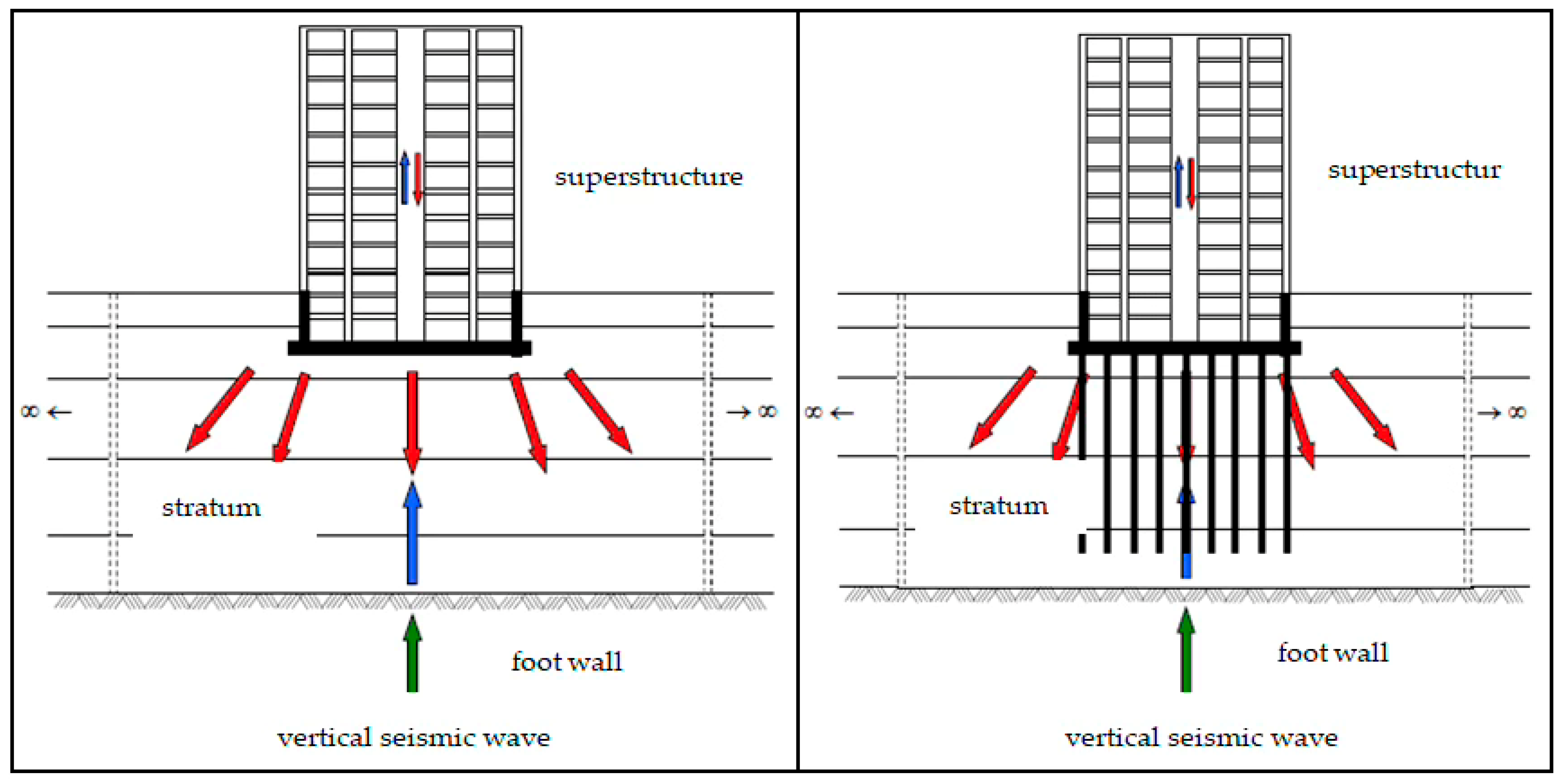
Structure–soil interaction refers to the mutual influence of the structure and soil within a coupled system under seismic loading, as illustrated in
Figure 1. Seismic waves, originating from the bedrock, propagate through the soil to the foundation, creating complex interactions. A portion of these waves is reflected back into the soil, while the remainder transmits to the superstructure, inducing vibrations and additional interactions. In pile-supported structures on soft soils, this interaction significantly impacts the seismic performance of piles, often leading to nonlinear deformations and changes in the mechanical properties of both the soil and piles. This behavior is analyzed through two primary mechanisms: kinematic interaction and inertial interaction. Piles are also subject to additional stresses due to earthquake waves returning from the vibrating pavement to the pile–soil environment within the scope of inertial interaction [
1].
Kinematic interaction arises from the soil–pile interaction during seismic wave transmission and reflection, focusing on pile deformations and bending moments independently of superstructure dynamics. Conversely, inertial interaction accounts for the dynamic response of the superstructure, which contributes to additional forces and deformations in the pile system. These coupled effects necessitate comprehensive analyses to ensure reliable seismic designs [
2,
3].
The Turkish Building Earthquake Code 2018 (TBEC-2018) [
4] mandates detailed analyses of pile behavior under seismic loading, introducing the common system and subsystem approaches for analyzing structure–soil interaction. The subsystem approach separates the analysis into kinematic and inertial interaction stages. The analysis methods that can be applied to these stages are referred to as Method I, Method II, and Method III, and their areas of application are defined in the Regulation based on the Seismic Design Category (SDC), Building Height Category (BHC), and Local Soil Class. With the Turkish Building Earthquake Code, which came into force in Turkey in 2019, analysis of piles that are under the influence of earthquakes has become mandatory, and two approaches have been determined, namely the “common system approach” and the “subsystem approach”, for the analysis of the structure–soil interaction and design under the influence of earthquakes.
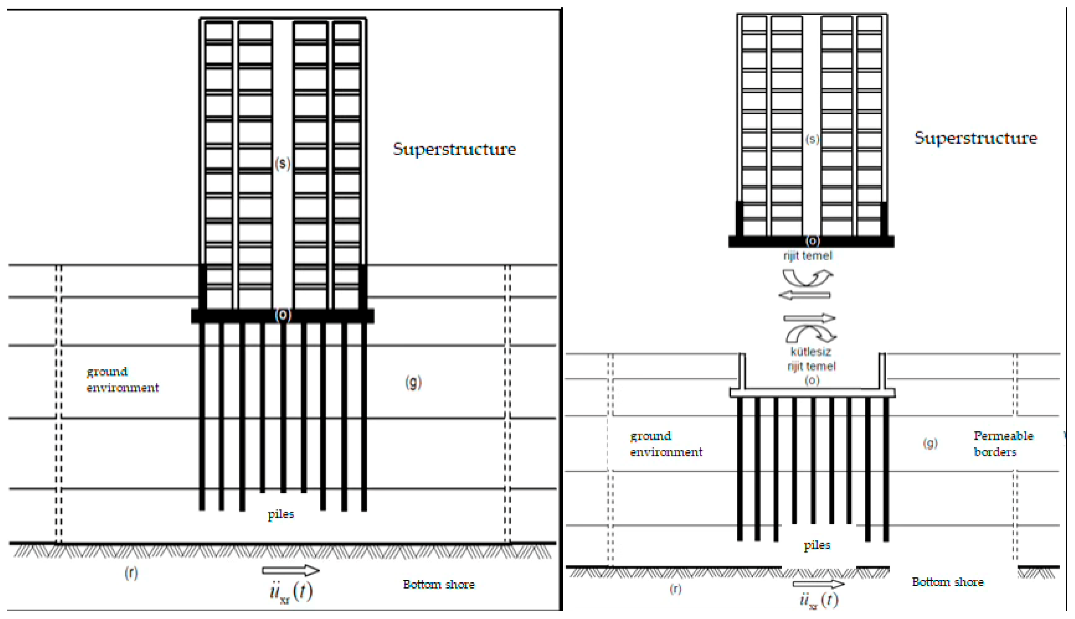
In the joint system approach, the superstructure and the ground are idealized as a single integrated system using a finite element model and analyzed under the influence of an earthquake defined at the bedrock level, as illustrated in
Figure 2. Kinematic analysis, a critical component, involves modeling the soil as nonlinear springs, performing site response analyses and applying soil displacements to finite element models of the pile–soil system. This approach has revealed that increasing pile diameters can lead to higher internal forces while reducing vertical displacements, thereby enhancing the stability [
5].
Advanced research has leveraged numerical modeling techniques and experimental methods to deepen the understanding of pile behavior under seismic conditions. Software packages like DEEPSOIL [
6] and SAP2000 [
7] facilitate the simulation of soil–pile interactions, accounting for nonlinear soil properties and dynamic effects. For instance, studies using 3D finite element modeling in ANSYS [
8] have shown that the pile diameter and length significantly influence the stress distribution and displacement under seismic loading, with larger diameters reducing lateral displacement but increasing internal stresses. Fixed-head pile group analyses using the Winkler beam method further elucidate the response of pile systems in layered soils [
2,
3].
In addition, the recent study by Qiu et al. (2024) titled “Application Study of the High--Strain Direct Dynamic Testing Method” applied a novel high-strain dynamic test for estimating the bearing capacity of piles in a bridge foundation case in Zhuhai, China. The results were compared with static loading tests and showed strong agreement, thus supporting the reliability of field-based pile response evaluation [
4]. This work complements the current study’s numerical analysis by providing empirical benchmarks for dynamic pile–soil behavior.
This study extends the current understanding by analyzing the kinematic interaction of single piles with varying diameters (65 cm, 80 cm, and 100 cm) based on Method III of the Turkish Building Earthquake Code 2018 (TBEC-2018). Using advanced numerical tools, including DEEPSOIL and SAP2000, it aims to provide insights into the relationship between pile diameter and seismic behavior, offering critical contributions to modern seismic design practices, particularly in terms of parametric trends, displacement–force relationships, and practical design implications for pile sizing under seismic kinematic loading. Despite the availability of general models, there remains a lack of detailed investigations specifically focusing on pile diameter variations under pure kinematic interaction using Method III of the TBEC-2018, especially with realistic site-specific input motion and empirical spring modeling.
2. Materials and Methods
The study of soil–pile interaction is critical for understanding the seismic behavior of pile foundations, particularly under the provisions of the Turkish Building Earthquake Code 2018 (TBEC-2018) [
4]. Method III in the TBEC outlines a structured approach for kinematic interaction analysis, which involves modeling soil as nonlinear springs, conducting site response analyses to determine soil displacements, and applying these to finite element models for pile behavior evaluation. The study focused on single piles embedded in soft clay, stiff clay, and loose sand profiles, analyzing variations in pile diameter (65 cm, 80 cm, and 100 cm) and their effects on internal forces and displacements under seismic loading conditions.
The numerical results showed that increasing the pile diameter significantly raised bending moments and shear forces, while lateral displacements were reduced, indicating enhanced lateral stiffness and improved seismic performance of the pile–soil system [
9]. The Modified Kondner–Zelasko (MKZ) model was adopted for both clay and sand to capture nonlinear modulus reduction and damping characteristics under seismic loading. Although site-specific parameters such as the overconsolidation ratio (OCR) and relative density (Dr) were not directly used due to data limitations, representative average values were selected based on regional soil data. This assumption is acknowledged in the Limitations section. Furthermore, significant variations in internal forces were observed at the interfaces of soil layers with differing levels of stiffness, emphasizing the role of soil stratigraphy in pile behavior. The transition between soft and stiff layers resulted in concentrated stress zones, aligning with findings from similar studies on stratified soil–pile interactions.
The seismic response analyses also highlighted the reduction in kinematic effects when piles were modeled as a group rather than individually. This effect is attributed to the collective resistance of piles within a group, which dampens soil displacement propagation [
2,
3]. The use of dynamic earthquake data, such as RSN1605_DUZCE_DZC270, enabled realistic modeling of seismic impacts, showing that larger pile diameters effectively mitigate displacement amplitudes but concentrate forces near pile heads, necessitating careful design considerations [
2]. The RSN1605_DUZCE_DZC270 ground motion was selected due to its strong relevance to Turkey’s seismic context. However, using a single ground motion is a limitation, and future studies will employ suites of spectrally compatible records incorporating the Arias Intensity and CAV for statistical robustness. Although only a single ground motion was selected in this study (RSN1605-Düzce, PGA = 0.51 g), the record was chosen due to its strong shaking characteristics and prior use in Turkish seismic geotechnical research. We acknowledge that a suite of spectrally compatible ground motions—including measures such as the Arias Intensity and CAV—would provide broader statistical insights and are recommended for future studies.
The soil profile and pile conditions are given in
Figure 3. The soil properties are presented in
Table 1. The listed values represent average representative parameters for each layer, based on typical values for the corresponding soil type and supported by standard correlations.
Under soft clay and loose sand conditions, piles with smaller diameters exhibited greater lateral displacement, indicating their vulnerability to seismic waves. However, as the pile diameter increased, the soil–pile stiffness ratio improved, reducing the displacement and enhancing stability. Specifically, increasing the diameter from 65 cm to 100 cm resulted in a ~50% reduction in vertical displacement and a 4-fold increase in bending moment, reflecting the nonlinear stiffness response of the soil–pile system under seismic loading [
10].
This research contributes to the growing body of research emphasizing the significance of the TBEC (2018)’s [
4] Method III for seismic pile design. It demonstrates the necessity of integrating soil behavior analyses with finite element methods to achieve safer and more resilient foundation systems in seismically active regions.
The P–y, T–z, and Q–z curves were defined using standard empirical models: Matlock (1970) for soft clays, O’Neill–Murchison (1983) for sands, and API RP 2A (2000) for general soil classification. While these models provide practical input formulations, they rely on broad soil categories and do not differentiate in detail between dense and very dense sands or between normally and overconsolidated clays. Therefore, they were applied cautiously with parameters that were representative of Turkish geotechnical practice. Future refinement could be achieved via calibration using local SPT-based correlations or direct load test data.
The soil–pile interaction was not directly modeled in DEEPSOIL, which only represents the free-field response. Instead, the interaction effects were captured via nonlinear springs assigned along the pile length in SAP2000. This uncoupled two-stage approach is widely used in practical seismic design, particularly in accordance with Method III of the TBEC 2018. The limitations of this approach are acknowledged and discussed in
Section 4.
Although fully coupled finite element or finite difference models offer more detailed simulations, the current method allows for a practical and parametric sensitivity evaluation, aligning with the primary aim of examining the influence of pile diameter under realistic boundary conditions.
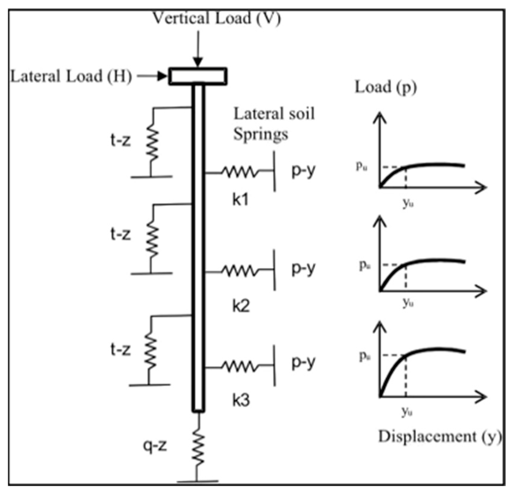
In the kinematic interaction analysis outlined in Method III of the Turkish Building Earthquake Code 2018 (TBEC-2018) [
4], soil behavior is represented through nonlinear spring elements, specifically P-y, T-z, and Q-z springs. These springs simulate the lateral, frictional, and end-bearing responses of the soil along the pile’s depth, respectively, with their stiffness properties being defined by nonlinear load transfer curves, as shown in
Figure 4.
P-y springs represent the lateral soil resistance and vary with depth, soil type, and pile movement, primarily capturing the bending behavior of piles.
T-z springs model the circumferential frictional response of the soil along the pile shaft an are crucial for evaluating skin friction under vertical loads.
Q-z springs simulate the end-bearing capacity at the pile tip, capturing the axial load transfer into deeper soil layers or bedrock.
These nonlinear springs are derived using empirical or semi-empirical methods from load transfer relationships that have been validated in the literature. Methods such as the Reese and Matlock (1956) approach [
11] or the API RP 2A (1993) guidelines are widely utilized for defining P-y curves, while T-z and Q-z spring properties are often developed based on soil test data, including the undrained shear strength for clays or the relative density for sands [
12]. Advanced modeling approaches also incorporate finite element analysis to generate these curves with higher precision for specific site conditions [
3,
13].
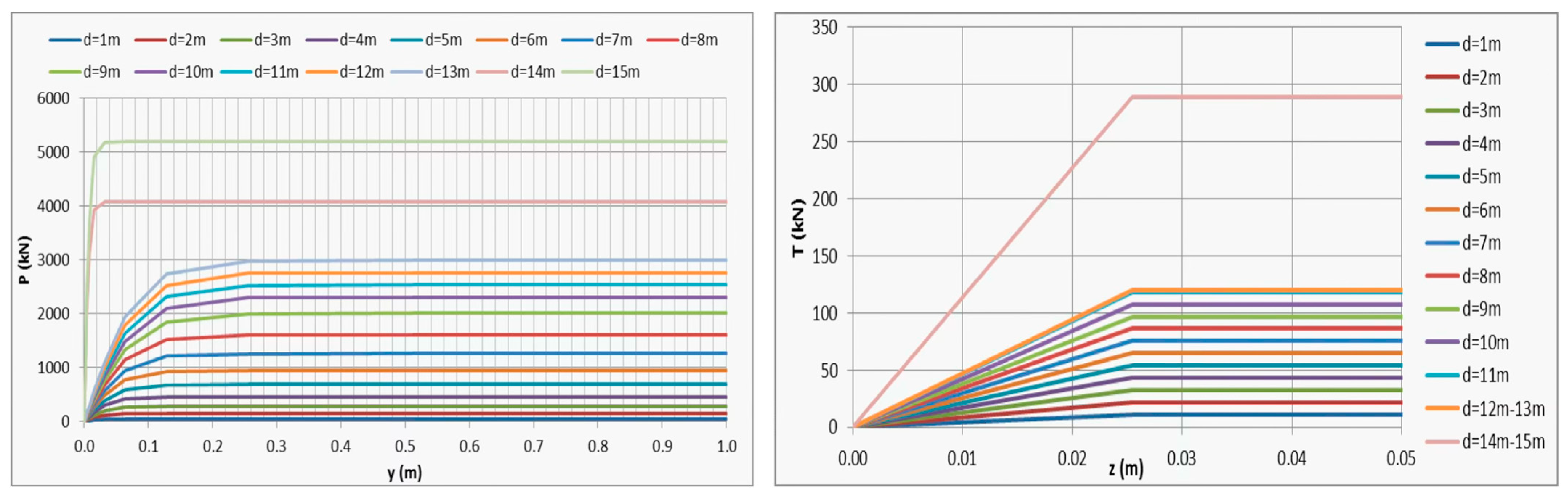
In this study, the P-y load transfer curves for cyclic loading in clay soils were derived using the Matlock (1970) model [
14], which is widely recognized for its ability to predict lateral soil resistance under cyclic conditions. For the T-z load transfer curves, the parameters and limit values recommended by the API (2007) guidelines [
15] were applied, ensuring an accurate representation of the shaft friction along the pile length. These curves account for soil–pile interaction mechanisms and are crucial for assessing the pile response under seismic and dynamic loading conditions.
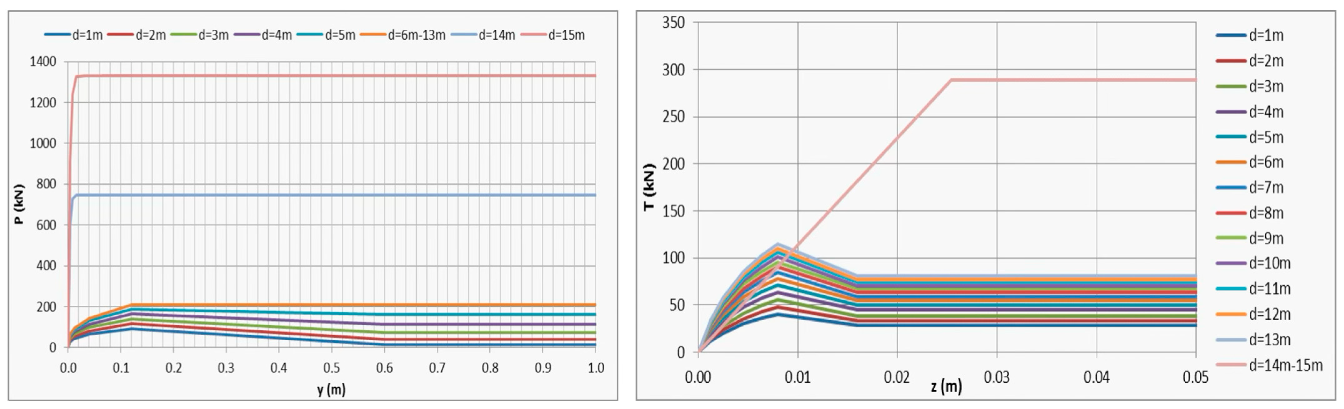
The soil–pile system was discretized into 1 m intervals along the pile length to obtain a detailed representation of soil stiffness variations. At each depth, load transfer curves were generated using numerical calculations performed in MS Excel, ensuring consistency and precision in the derived parameters. A discretization interval of 1 m was chosen based on prior studies showing sufficient resolution for nonlinear spring modeling. Nevertheless, refined intervals (e.g., 0.5 m) near critical interfaces such as the pile toe may improve accuracy and will be considered in future models.
This methodological approach is supported by existing standards and research, including the use of empirical models for load transfer relationships, which provide essential inputs for advanced numerical analysis and design [
14,
15,
16]. Such detailed modeling is pivotal for capturing the nonlinear behavior of soil–pile systems under lateral and axial loads. The load transfer curves were obtained for each depth using the MS Excel software. The P-y and T-z curves for an 80 cm pile diameter in Soil Profile 1 are presented in
Figure 5.
For sandy soils, P-y load transfer curves were developed for cyclic loading conditions using the O’Neill and Murchison (1983) model [
17], which offers robust predictive capabilities for lateral soil resistance under repeated load applications. The T-z load transfer curves, accounting for the axial shaft resistance, were determined using the parameters and limit values outlined in the API (2007) standards [
15]. This dual-model approach ensures a reliable representation of soil–pile interaction for dynamic analysis.
To enhance the resolution in the analysis, the soil–pile system was discretized into 1 m intervals along the pile length. At each depth, the corresponding P-y and T-z load transfer curves were generated via numerical computations performed in MS Excel, facilitating precise modeling of the soil’s behavior and interaction with the pile.
Figure 6 illustrates the P-y and T-z curves for an 80 cm diameter pile within Soil Profile 3, highlighting the variations in soil resistance characteristics with depth. This approach is appropriate for cyclic and seismic conditions [
15,
17,
18].
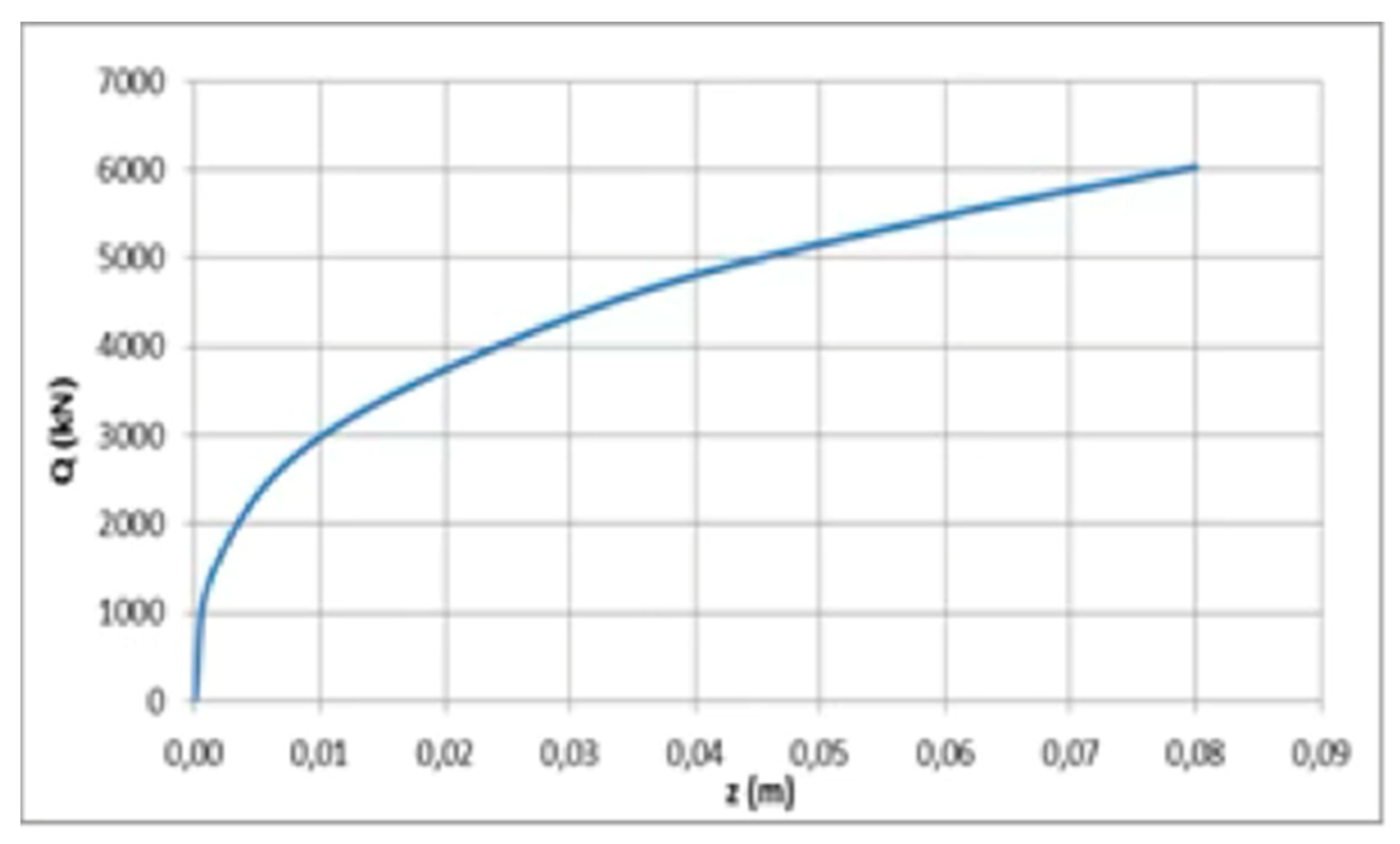
In all soil profiles, the Q-Z load transfer curve for the pile tip in the underlying very dense sand soil was obtained using the model and limit values recommended by API (2007) [
15]. The Q-Z curve for the pile tip with an 80 cm diameter in Soil Profile 3 is presented in
Figure 7.
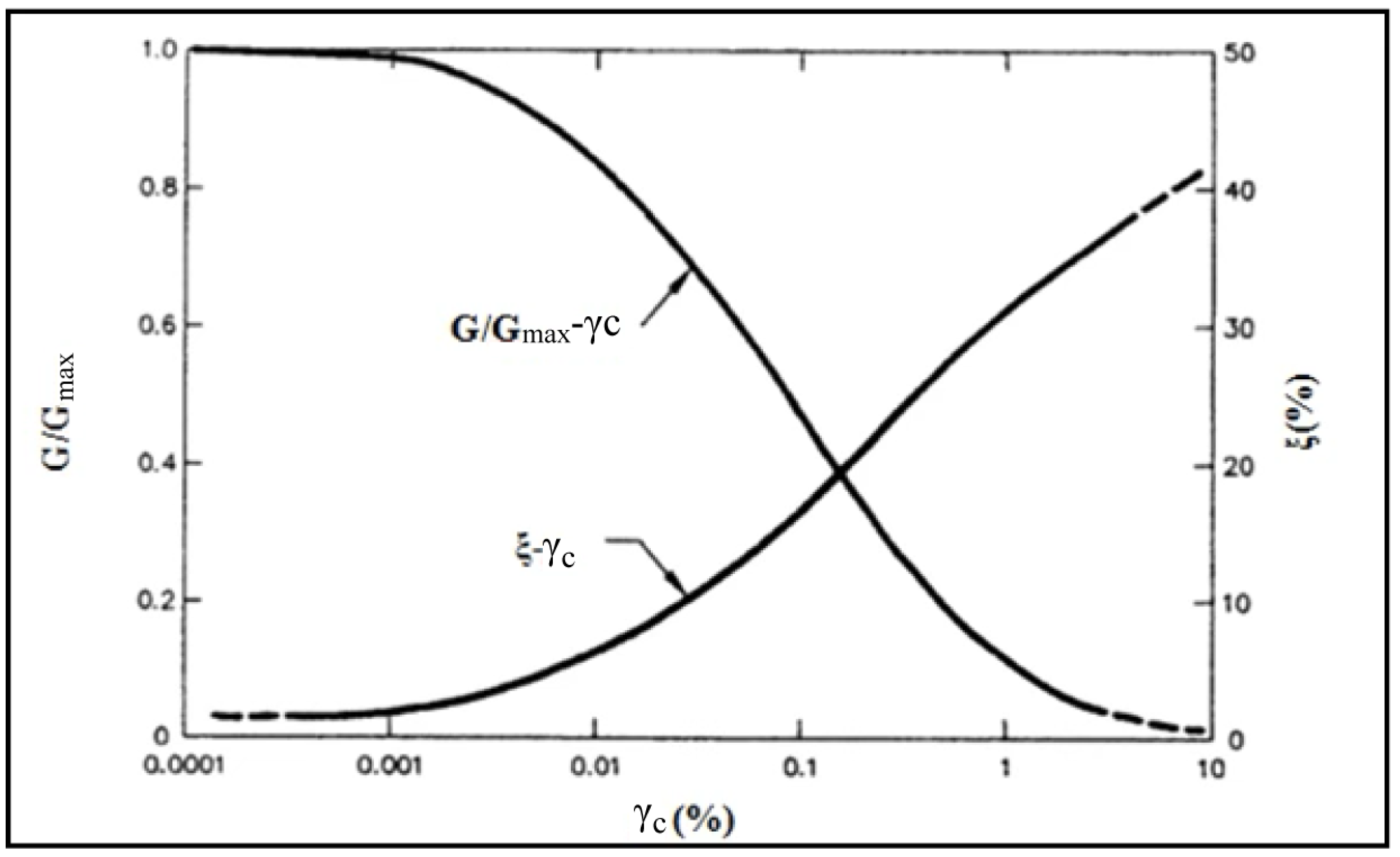
In the soil behavior analysis, the propagation of stress waves—generated by seismic ruptures—from the earthquake source to the surface is modeled to evaluate the response of soil layers and their impact on the foundation’s behavior. This process requires selecting key parameters, such as the seismic ground motion, dynamic soil properties, and dynamic analysis method, along with essential information such as the bedrock depth and groundwater level, if applicable. Dynamic soil properties are characterized by factors such as the shear wave velocity, unit weight, and the soil model. The variation in the shear modulus (G) and damping ratio (ξ) with strain level (γc) is crucial for capturing soil’s behavior under dynamic loading. These parameters are often derived from laboratory or in situ tests, supplemented by empirical correlations where direct measurements are unavailable. This data is typically represented as nonlinear relationships, reflecting the reduction in stiffness and increase in damping with increasing strain, as shown in
Figure 8.
Using this information, soil displacements due to seismic excitation at the bedrock are analyzed in the time domain or frequency domain. Such analysis helps determine the amplification effects and resulting soil displacements, providing critical insights for foundation design and site-specific seismic assessments [
19,
20].
According to Method III of the Turkish Building Earthquake Code (TBEC-2018) [
4], the kinematic interaction analysis involves conducting a one-dimensional free soil behavior analysis under seismic excitation. This analysis computes the total displacements at pile node alignments along the soil profile by applying the determined earthquake-induced displacements to P-y springs, which model the soil’s lateral response.
In this study, the DEEPSOIL software, developed under the guidance of Prof. Youssef Hashash at the University of Illinois, was used for soil behavior analysis. DEEPSOIL is designed specifically for the analysis of horizontally layered soils and supports a range of methods, including linear and equivalent linear analyses in the frequency domain and nonlinear analyses in the time domain. This versatility makes it suitable for modeling the complex dynamics of soil–pile interactions.
For this research, the Modified Kondner–Zelasko (MKZ) model was employed for both clay and sandy soils to represent nonlinear soil behavior. The soil profile was discretized into one-meter layers within DEEPSOIL, aligning with the intervals that were used for spring displacement calculations. The seismic input was derived from the RSN1605 DUZCE DZC270 earthquake record, sourced from the PEER Ground Motion Database, ensuring realistic representation of the seismic loading conditions.
In this study, DEEPSOIL (v7.0) was employed solely to perform 1D nonlinear site response analyses and to generate surface-level acceleration time histories for each soil profile. These outputs were used as seismic inputs in SAP2000, where the single pile was modeled using the beam-on-nonlinear-Winkler-foundation (BNWF) approach with empirically derived P–y, T–z, and Q–z curves.
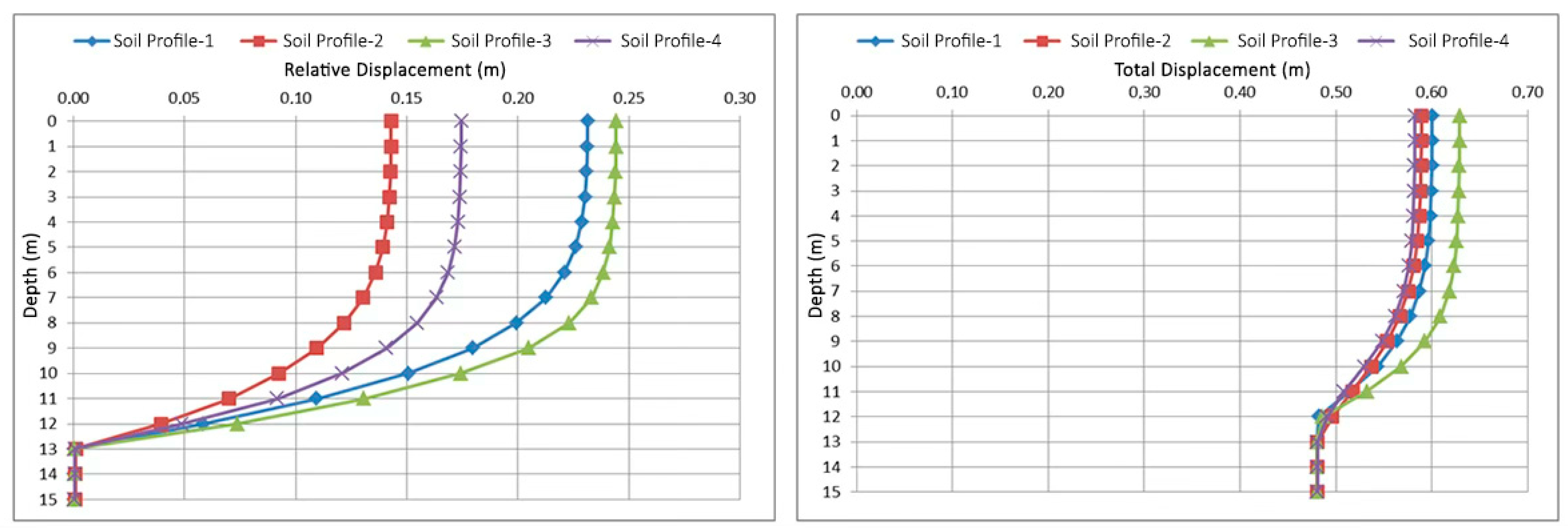
Once the soil profile and input motion data were defined, a nonlinear one-dimensional soil behavior analysis was performed in the time domain. This analysis yielded relative displacement graphs for each soil layer over time. The total displacements were calculated by summing the relative displacements and the baseline bedrock displacements.
Figure 9 illustrates the relative and total displacements for all soil profiles, demonstrating the differential movement characteristics across varying soil types and depths under seismic loading.
Under weak soil conditions, piles and building foundations experience significant strains due to the interaction of seismic waves originating from the bedrock and propagating through the soil. This phenomenon, known as kinematic interaction, evaluates the effects on the foundation–pile–soil system without considering the inertial forces of the superstructure. Additionally, inertial interaction arises when seismic forces from the superstructure induce further stresses in the pile–soil medium, necessitating comprehensive analysis for design under seismic conditions.
The Turkish Building Earthquake Code (TBEC-2018) [
4] outlines two primary approaches for addressing these interactions: the common system approach and the subsystem approach. The common system approach treats the superstructure, foundation, and soil as a unified finite element model, enabling simultaneous analysis under seismic loading. Conversely, the subsystem approach divides the analysis into two distinct subsystems, the superstructure–foundation subsystem and the foundation–pile–soil subsystem, while accounting for their mutual interactions (
Figure 2).
For this study, the subsystem approach was adopted, and kinematic interaction analysis was performed using SAP2000 [
7], a finite element analysis (FEA) software developed by Computers & Structures Inc (Computers & Structures, Inc., located in Walnut Creek, California, USA). This software is capable of conducting static and dynamic, linear and nonlinear analyses of structural systems with varying complexities. In SAP2000 [
7], complex geometries are discretized into finite elements to compute stress responses, which are later combined to achieve accurate global analysis results.
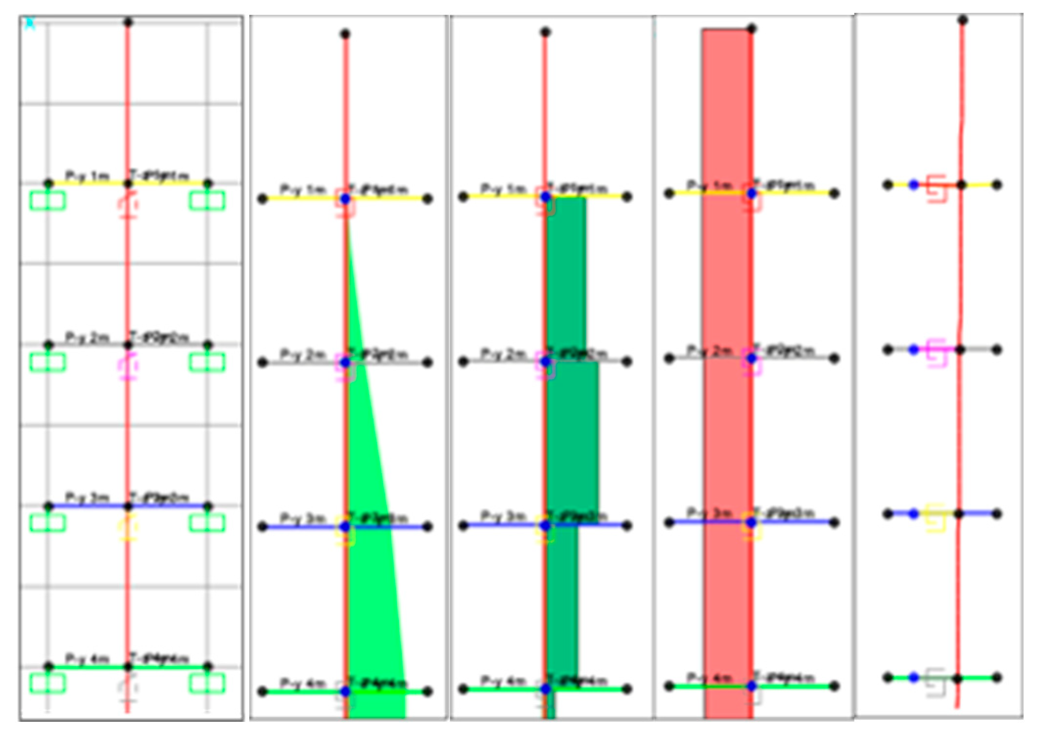
To simulate soil–pile interaction, P-y and T-z nonlinear springs were modeled for each 1 m depth of the pile to represent the lateral and frictional soil resistance, respectively. Additionally, Q-Z springs were used at the pile tip to capture the end-bearing resistance. The load transfer curve data, derived from earlier analyses, were integrated into the nonlinear springs. The pile itself was modeled as a beam element, while the springs were represented as nonlinear connection elements.
In the SAP2000 model, the pile was idealized as a linear elastic beam element, discretized at 1 m intervals. Nonlinear soil behavior was represented through lateral (P-y), shaft friction (T-z), and end-bearing (Q-z) springs. The base of the pile was assumed to be vertically restrained to simulate end-bearing in very dense sand, while rotational freedom was allowed to capture bending effects. No structural inertial loads were applied at the pile head, as the analysis was limited to kinematic interaction as per the TBEC 2018’s Method III. These assumptions ensure that the numerical simulation reflects only the effects of soil-induced ground motion, consistent with the scope of the study.
In this analysis, a vertical load of 500 kN was initially applied to the pile head to simulate structural loads. Subsequently, incremental horizontal displacement loads were applied to evaluate pile performance under combined vertical and lateral loading. The resulting outputs included maximum vertical and horizontal displacements, as well as internal force parameters such as moment (M), axial force (N), and shear force (T). These results, shown in
Figure 10, provide insights into the behavior of piles under seismic loading and their capacity to withstand dynamic forces.
3. Results and Discussion
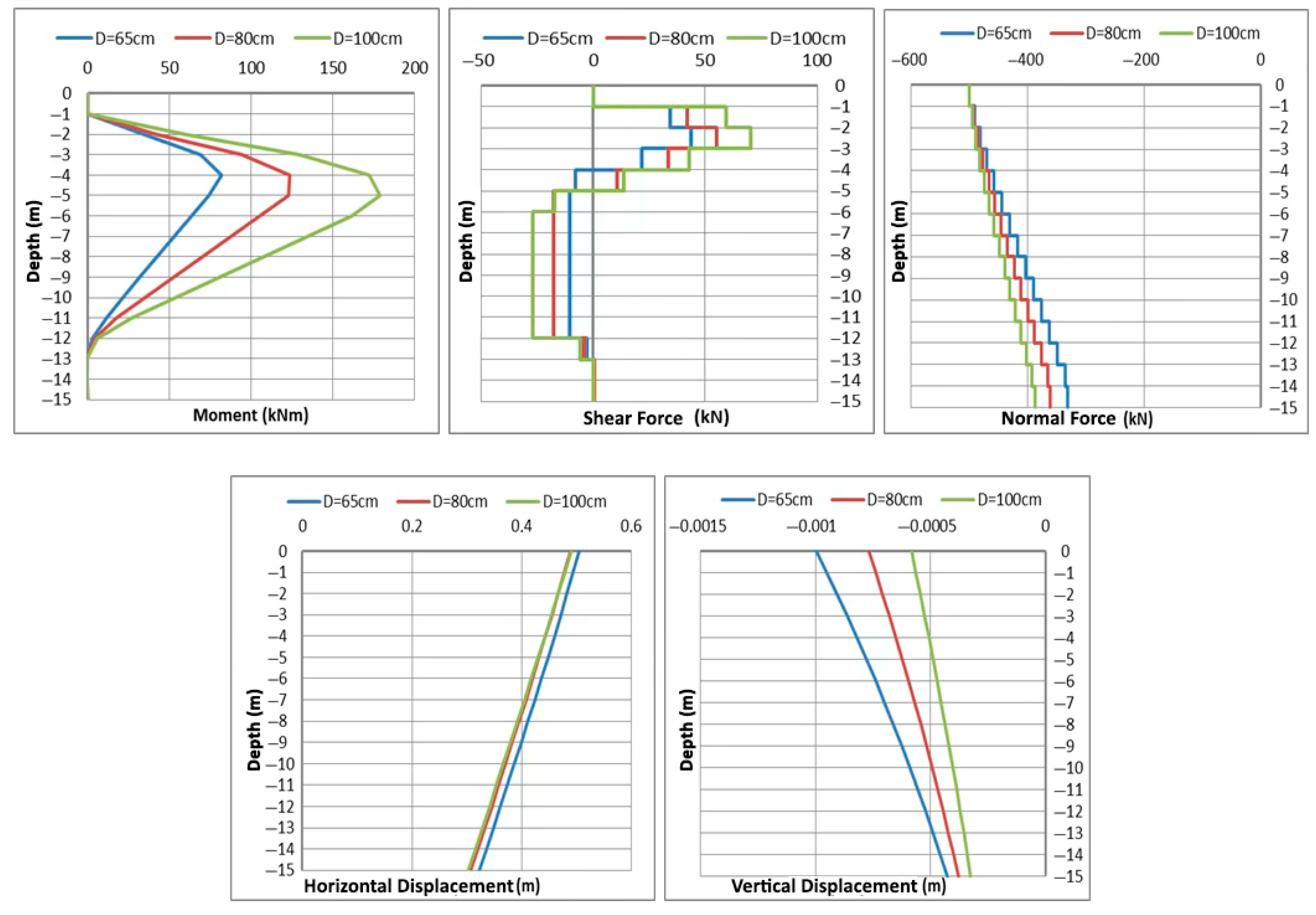
The results of the kinematic interaction analyses of pile–soil systems with varying pile diameters (65 cm, 80 cm, and 100 cm) revealed significant impacts on internal forces and displacements. Increasing the pile diameter led to a rise in the stiffness of the soil springs, which in turn caused higher horizontal forces acting on the pile for a given soil displacement load. This relationship was evident in the maximum internal force values, where the maximum moment increased 2.5 times and the maximum shear force increased 1.5 times as the pile diameter expanded from 65 cm to 100 cm. The distribution of moments indicated that the highest values occurred at a critical depth of approximately 5 m and diminished thereafter, consistent with findings from similar studies such as those by Bildik et al. (2017). Minimal moment and shear forces were observed at the pile’s tip, attributed to socketing in a stable soil zone, which reduces the total soil displacement loads [
21].
The horizontal displacement analysis showed that the pile displaced maximally at the top, with displacements decreasing towards the base. Changes in pile diameter had negligible effects on the maximum horizontal displacement, likely due to the limited influence of diameter changes on the spring stiffness under the given soil conditions and the stabilization provided by the socketing effect. However, vertical displacements were significantly influenced by the pile diameter; larger diameters enhanced spring stiffness, resulting in reduced vertical displacement. In particular, it was observed that when the pile diameter increased from 65 cm to 100 cm, the maximum vertical displacement was reduced by half, highlighting the role of the diameter in reducing collapse. These results provide crucial insights into optimizing pile design under varying soil and seismic conditions, as shown in
Figure 11.
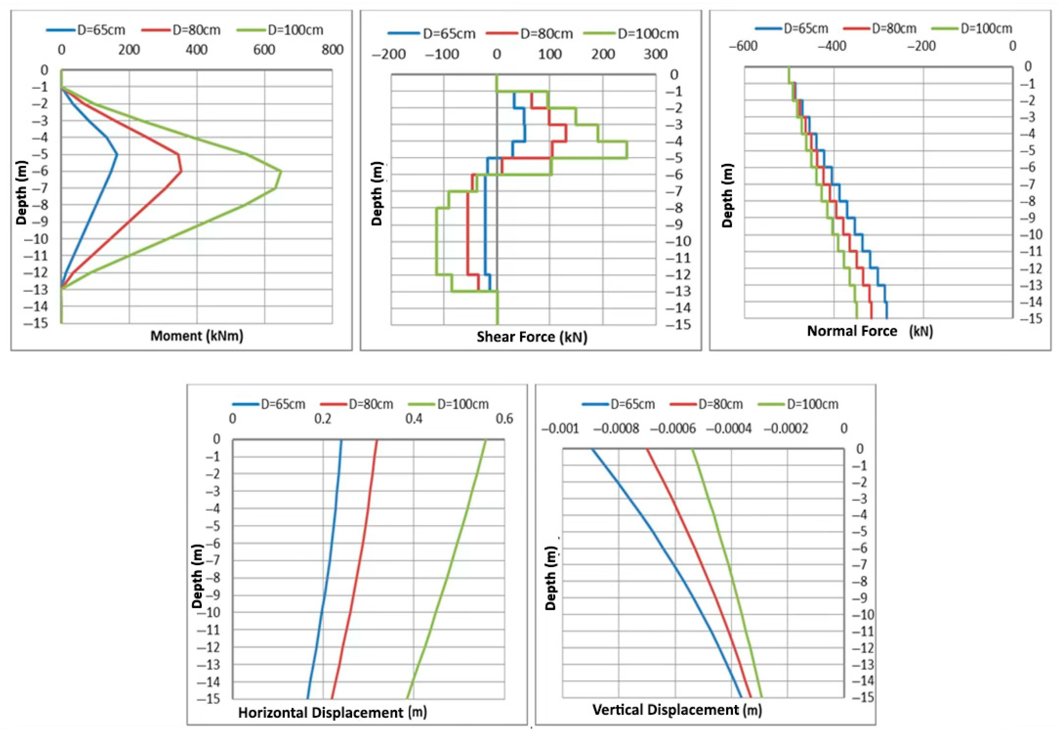
In the kinematic interaction analysis for Soil Profile 2 (stiff clay), the results show a similar trend to those obtained from Soil Profile 1 (soft clay), with some distinct differences in the behavior of internal forces and displacements. The depth at which the maximum moment and shear forces occurred shifted from 5 m to the 6th meter due to the higher stiffness of the soil. The greater stiffness in stiff clay compared to soft clay increases the spring rigidity, leading to a higher horizontal load being transferred onto the pile as the pile diameter increases. This, in turn, causes a more significant effect of the pile diameter on the internal forces and displacements in stiff clay than in soft clay.
When the pile diameter increases from 65 cm to 100 cm in stiff clay, the maximum moment increases four-fold, and the maximum shear force increases by 4.5 times. The vertical load remains constant, so the axial force does not change, but the maximum horizontal displacement of the pile increases by 2.5 times. Similarly, the vertical displacement is reduced by half due to the increased spring stiffness, reflecting the improvements in soil properties and the corresponding changes in pile behavior, as shown in
Figure 12.
These findings align with the general principles of pile behavior in stiff soils under seismic loading, where the soil’s stiffness plays a crucial role in determining the pile’s response, particularly in terms of moment and shear force magnitudes [
14,
15,
20].
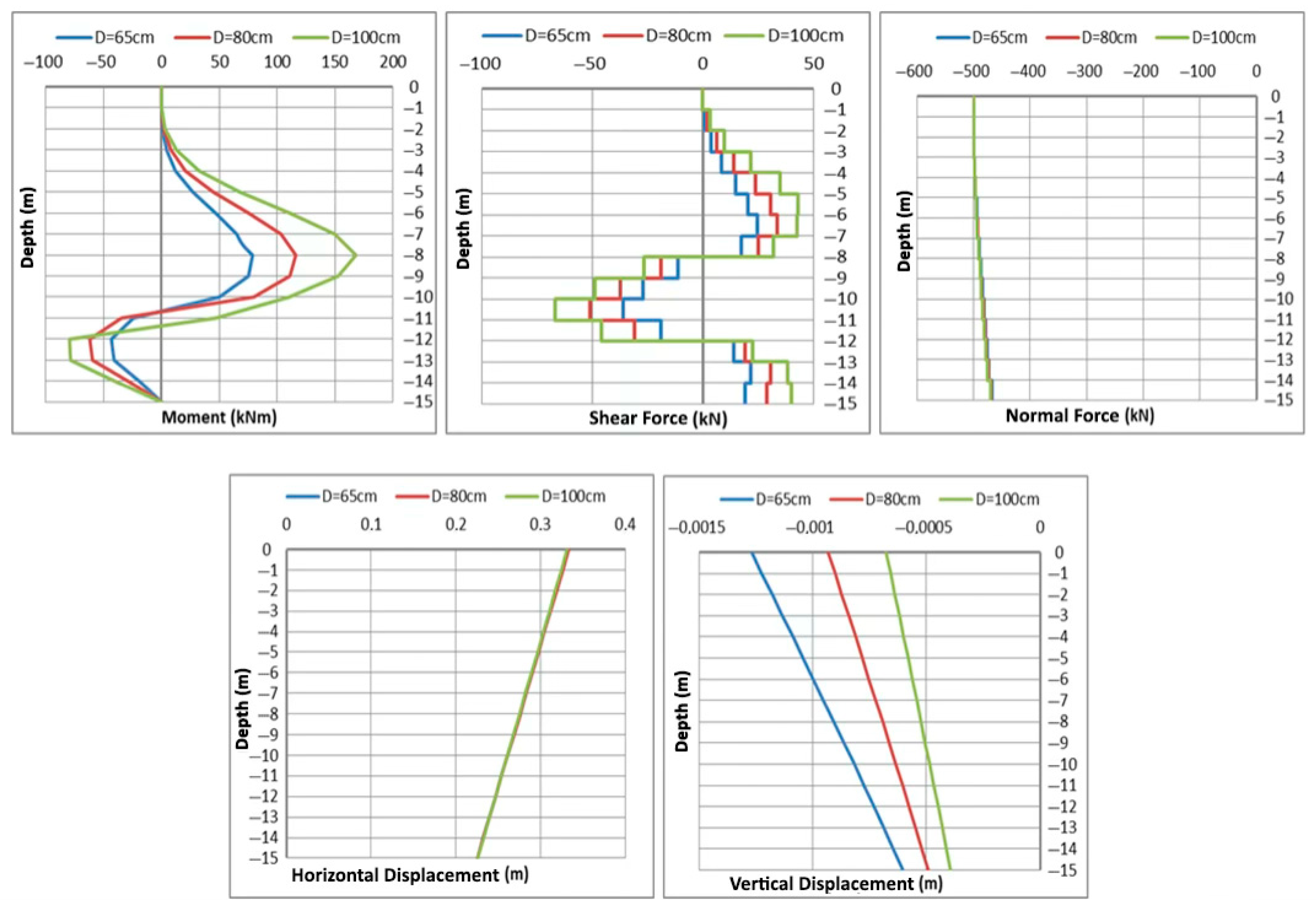
The kinematic interaction analysis conducted in Soil Profile 3 (very loose sand-A) revealed that the moment increases as the pile depth increases, reaching its peak at the 9th meter. This increase is primarily due to the increasing number of horizontal springs and their stiffness. After the 9th meter, the moment decreases because of the reduced soil displacement load and changes direction due to the influence of very dense sand at the base of the pile. When comparing sandy soils to clay soils, it is observed that sandy soils transfer significantly more horizontal force to the pile for the same displacement load. This difference in behavior is attributable to the distinct characteristics of P-y curves in sandy soils, as shown in earlier figures. The combination of these internal dynamics, particularly the impact of P-y curves, leads to increased horizontal forces in the dense sand zone where the pile is socketed.
As the pile diameter increases from 65 cm to 100 cm, the maximum moment increases by a factor of 2.5, and the maximum shear force increases by 2 times. For all pile diameters, the axial force, which is maximum at the top of the pile, decreases gradually towards the bottom due to the nature of T-z curves in sandy soils. Despite the changes in pile diameter, the pile’s horizontal displacement remains largely unchanged, because the rate of change in the pile diameter is not significant enough to reflect a major shift in spring stiffness, especially when considering the characteristics of P-y curves. On the other hand, the vertical displacement decreases as the number and stiffness of vertical springs increase with the pile diameter. Specifically, as the pile diameter increases from 65 cm to 100 cm, the maximum vertical displacement is reduced by half, as shown in
Figure 13.
This behavior highlights the critical influence of the soil type, pile diameter, and soil–spring interaction in determining pile responses under lateral and vertical loading conditions in seismic environments.
The kinematic interaction analysis conducted in Soil Profile 4 (very loose sand-B) revealed that the dynamics of internal forces and displacements are similar to those observed in very loose sand-A, given the similarity in the soil properties of the two profiles. However, due to an improvement in soil conditions, the maximum horizontal internal forces and displacements observed in very loose sand-B are lower compared to those in very loose sand-A. This can be attributed to the better structural properties of the soil, which influence the interaction behavior of the pile.
As the pile diameter increases from 65 cm to 100 cm in this soil profile, the maximum moment value doubles. This is consistent with the general trend observed in sandy soils, where an increase in pile diameter leads to an increase in the internal moment and shear forces due to a higher number of springs and their stiffness. However, the rate of increase in the maximum moment is not as pronounced as in the previous soil profiles, indicating that the improvements in soil conditions are having a mitigating effect on the pile’s response, as shown in
Figure 14. The horizontal displacement still remains largely unchanged across the different pile diameters, and the vertical displacement decreases similarly to what was observed in the very loose sand-A soil profile, reflecting the increase in vertical spring stiffness with pile diameter. The adopted modular analysis framework—while practical—does not fully capture the coupled dynamic soil–pile–superstructure interaction. Future studies may consider using integrated FE or FD approaches (as, e.g., in Wang et al., 2023) for more comprehensive modeling [
22].
One of the primary limitations of this study is the use of a single ground motion record. Although this allows for controlled parametric comparison across pile diameters, it does not capture the variability in spectral content, intensity, or duration. The inclusion of ground motion suites that are matched to target spectra, and the consideration of the Arias Intensity and CAV, as highlighted in recent Turkish GMPE studies (Akkar et al., 2014), would enhance the robustness of future findings [
23].
While the increased stiffness in stiffer clay layers contributes to enhanced spring constants and hence larger internal forces, the total seismic response is also significantly influenced by the site’s fundamental period. When the site period approaches the predominant period of the input motion (e.g., Tm or Tp), resonance effects can lead to amplified displacement and force responses. This may explain certain inconsistencies observed between Soil Profiles 2 and 3. Similar findings were reported by Raghunandan and Liel (2020), who demonstrated that amplification depends on spectral compatibility and pulse-like content [
24].
4. Conclusions
This study explored the influence of pile diameter on the seismic response of single piles using kinematic interaction analysis in accordance with Method III of the Turkish Building Earthquake Code (TBEC-2018) [
4]. The numerical modeling framework integrated nonlinear soil springs (P-y, T-z, Q-z), site response analysis with DEEPSOIL [
6], and structural simulation in SAP2000 [
7], allowing for a detailed investigation of the pile–soil system when subjected to seismic loading. The results indicate that increasing the pile diameter from 65 cm to 100 cm leads to significant variations in internal force demands and displacement behavior. Specifically, the maximum bending moment increased by up to 4.0 times, while the shear force increased by approximately 4.5 times. In contrast, vertical displacements were reduced by nearly 50%, highlighting the role of enhanced pile–soil stiffness in seismic performance. Horizontal displacements remained relatively constant, likely due to the nonlinear behavior of soil springs and the socketing of the pile into denser layers [
9,
14]. The depth at which maximum internal forces occurred varied depending on the soil profile. In soft and stiff clays, the critical depth ranged between 5 and 6 m, while in sandy profiles, peak bending moments were observed deeper due to the influence of varying levels of spring stiffness. Transitions between stratified layers caused localized stress concentrations, emphasizing the need to account for soil heterogeneity in seismic design [
13,
20]. Furthermore, this study confirms that the pile geometry plays a critical role in seismic response and that Method III of the TBEC-2018 provides a practical yet technically robust framework for evaluating kinematic interaction. The simplified modeling approach using nonlinear springs is effective in capturing the essential features of soil–pile interaction under earthquake-induced displacements [
11,
15,
17]. However, for comprehensive seismic design, inertial effects from the superstructure and potential liquefaction should also be considered in future studies [
25]. In summary, the findings offer useful parametric insights for the design of pile foundations in seismically active regions, particularly in stratified soil conditions. The outcomes support the application of the TBEC-2018’s Method III as a valuable tool for engineers aiming to optimize the pile diameter and embedment depth in light of seismic performance objectives. Although widely adopted, the empirical load transfer models used in this study should be further calibrated with in situ test data to better reflect the behavior of locally encountered soil types.
Advanced nonlinear modeling techniques in recent studies provide a more accurate prediction of soil–pile interactions under seismic loading. These approaches account for nonlinear soil behavior, liquefaction potential, and pile diameter effects, revealing that stiffer soils produce smaller displacements but higher internal forces compared to softer soils (
Table 2) [
25,
26,
27]. Moreover, the use of thixotropic soil models has shown that the viscosity and cyclic loading significantly influence the response of piles during seismic events, necessitating detailed modeling for effective design [
22].
Although this study provides insights into the influence of pile diameter under pure kinematic interaction, it does not capture the full complexity of soil–structure interaction during real seismic events. Inertial effects from the superstructure mass, the nonlinearity of pile materials, and cyclic degradation of soil stiffness were beyond the scope of this analysis but are acknowledged as critical factors for future studies [
23,
24].
Additionally, the results were not validated against field-scale data. Future work should incorporate centrifuge or full-scale test data from Turkish seismic regions and employ fully coupled finite element tools (e.g., PLAXIS, OpenSees) for more robust analysis.
For comparison, Bildik et al. (2023) presented a multi-parametric study including inertial interaction using nonlinear time history analysis. Their approach provides a valuable complement and confirms that the pile diameter significantly affects internal forces under full dynamic loading scenarios [
21]. Unlike Bildik et al. (2023), who used 3D finite element analysis for inertial interaction and pile groups, this study focuses on simplified kinematic analysis of single piles based on Method III. This complementary approach is now clarified in the revised manuscript [
21].
To date, no full-scale or centrifuge test data are available from Turkish seismic zones for direct validation. The spring models used are widely accepted and based on international validation studies.


 ,
, 


