1. Introduction
Stay cables are an integral part of cable-stayed bridge structures. Due to the long-term fatigue load on the cable and their exposure to wind, rain, humidity, and polluted air in regions such as river crossings and bay crossings, they are prone to corrosion. Consequently, the stay cables are the components most susceptible to damage in cable-stayed bridge structures. Cable damage not only affects the mechanical performance of the cable, leading to changes in its internal forces, but also impacts the associated components connected to it. Under the combined effect of external complex loads, damage to the cable can lead to changes in the internal forces of the entire bridge, which in turn affect the overall bridge structure [
1]. Variations in cable forces inevitably affect the entire bridge structure, influencing its static characteristics. Key indicators for assessing the operational safety of a damaged cable-stayed bridge include main beam deflection and main tower displacement. Examining the changes in static performance before and after cable damage can offer insights into the operational status of the cable-stayed bridge structure.
The issue of cable damage is primarily studied through numerical simulations, experiments, and theoretical analyses. Some researchers have conducted scaled experiments to investigate the impact of cable damage on bridge structures [
2]. By establishing cable models under various stress conditions, they assess the ultimate state of the damaged cables [
3]. Utilizing a scaled model of a cable-stayed bridge, the study examines the impact of temperature loading on the response of bridges with damaged cables. Additionally, a damage identification method based on temperature loading is proposed [
4].
Numerical simulation of cable damage typically encompasses a range of damage conditions, including various damage locations, extents, and multiple damage sites. Both experimental and numerical analysis methods are employed to examine the impact of cable damage locations and the extent of damage quantities on the structure [
5]. When a cable sustains damage, the stress in the main girder and the internal forces within the cable are redistributed. The impact of the damage on the structure’s natural frequency is more significant when the damage occurs near the anchorage zone. However, the experiment only considers the effect of the structure’s own weight and does not account for the coupling effects between loads. The damage to the long cables in the side spans significantly affects the static performance of the entire bridge and exhibits a composite characteristic. Damage to other cables primarily affects nearby areas and exhibits regional characteristics [
6]. The damage to the back cables and mid-span cables caused by vehicle live loads significantly affects the static structural parameters of the entire bridge, including the alignment of the main girder and the tension forces in the cables. It also significantly affects the dynamic characteristics of the entire bridge [
7].
The analysis of the natural frequency variation pattern of the cable-stayed bridge under various cable damage conditions revealed that damage to the longer cables substantially impacts the lower-order natural frequencies of the bridge, while having minimal effect on the higher-order natural frequencies. Conversely, damage to the shorter cables has almost no effect on the frequencies of the lower-order vibration modes of the cable-stayed bridge, but it significantly impacts the higher-order frequencies [
8]. A method for analyzing the dynamic and static characteristics of damaged cables, based on a micromechanical damage model, has been proposed. It establishes the governing equation for the free vibration of the damaged cable. This method assumes that the cable breakage mode is symmetrical. As the number of symmetrically broken wires within the cable increases, both the horizontal component of the cable force and the natural vibration frequency in the cable plane exhibit a decreasing trend. Under these damage conditions, the cable force and natural frequency are unaffected by the location of the wire breakage [
9].
The solid element method is utilized to simulate local corrosion damage in stay cables of different lengths and depths. The analysis focuses on the alterations in cable forces and the deflections of the main girder due to the breakage of stay cables or localized corrosion damage [
10]. Through the simulation of fractures and varying degrees of damage in typical long, medium–long, medium, and short cables within the finite element model of a cable-stayed bridge, this study investigates the impact of cable damage at different locations on the main beam’s profile [
11]. By utilizing a spatial finite element model for the mechanical analysis of cable damage, this study investigates the impact of cable damage on the deflection and cable forces of a cable-stayed bridge [
12].
In summary, cable damage is significantly correlated with the structural performance of cable-stayed bridges. This study investigates the variations in the static performance of bridges under different damage conditions, clarifying the relationship between changes in cable status and the overall performance of the entire bridge. Establishing a comprehensive understanding of how cable damage affects the static performance of cable-stayed bridges is of critical practical value for the safety assessment of bridges following long-term operation.
This article uses a certain three-tower cable-stayed bridge as the engineering background, using cable damage as the entry point to establish a finite element correction model that accurately reflects the existing structural characteristics. By employing static analysis methods, it analyzes the bridge state under cable damage, comparing the effects of single-cable damage and multiple-cable damage at different levels and locations on the static performance of the cable-stayed bridge. It identifies the cables that have a more significant impact on the structure and the patterns of how cable damage affects the bridge’s static performance, providing a foundation for assessing the bridge’s safety and designing cable replacement schemes.
2. Introduction to the Project Background
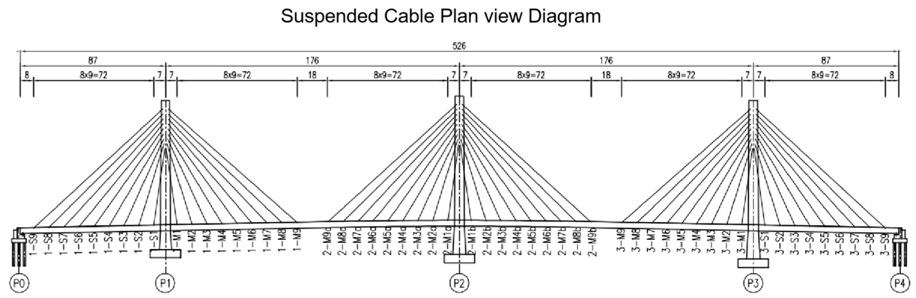
A certain three-tower cable-stayed bridge adopts a floating system with elastic restraints. The bridge has a span arrangement of 87 m + 176 m + 176 m + 176 m + 87 m. The main girder is constructed as a fully welded steel box girder, with a standard deck width of 57 m, accommodating 10 two-way lanes along with pedestrian and bicycle lanes. The longitudinal gradient is 2%, while the deck cross slope is 1.5%. The bridge consists of three towers, constructed with a steel–concrete composite structure, and the main towers range in height from 89.27 m to 94.99 m. The stay cables are arranged in a spatial fan-shaped configuration, totaling 108 cables across the entire bridge. Each tower is designed with 18 cable pairs, utilizing a steel strand group anchorage system. The diameter of a single steel strand is 15.2 mm, with a standard strength of 1860 MPa. Depending on the cable force, the stay cables are designed with two specifications: 34 steel strands and 43 steel strands. The longitudinal spacing of the cables on the girder is 9.0 m, the transverse spacing is 48.5 m, and the spacing on the tower is 3 m. The overall bridge layout is shown in
Figure 1.
3. Establishment of Finite Element Model
The finite element model of the cable-stayed bridge was established using ANSYS 8.0 software. The steel box girder main beam structure was modeled using beam4 elements with an elastic modulus E = 2.06 × 10⁵ MPa, density ρ = 7850 kg/m3, and Poisson’s ratio v = 0.31. The main tower, designed as a hybrid structure of steel and concrete, utilized the beam4 element. For the concrete segment of the main tower, the elastic modulus was set to E = 3.60 × 10⁴ MPa, the density was ρ = 2600 kg/m3, and the Poisson’s ratio was v = 0.2. For the steel segment of the tower, the elastic modulus was set to E = 2.06 × 10⁵ MPa, the density was ρ = 7850 kg/m3, and the Poisson’s ratio was v = 0.31. The cross-sections of the main girder and the main tower were analyzed using the equivalent section method. Finite element software was utilized to calculate the sectional properties, which were subsequently used to define the sectional constants. Stay cables are modeled using link4 elements, with the real constants of the cables determined based on the cable forces at various positions, effective areas, and equivalent elastic modules.
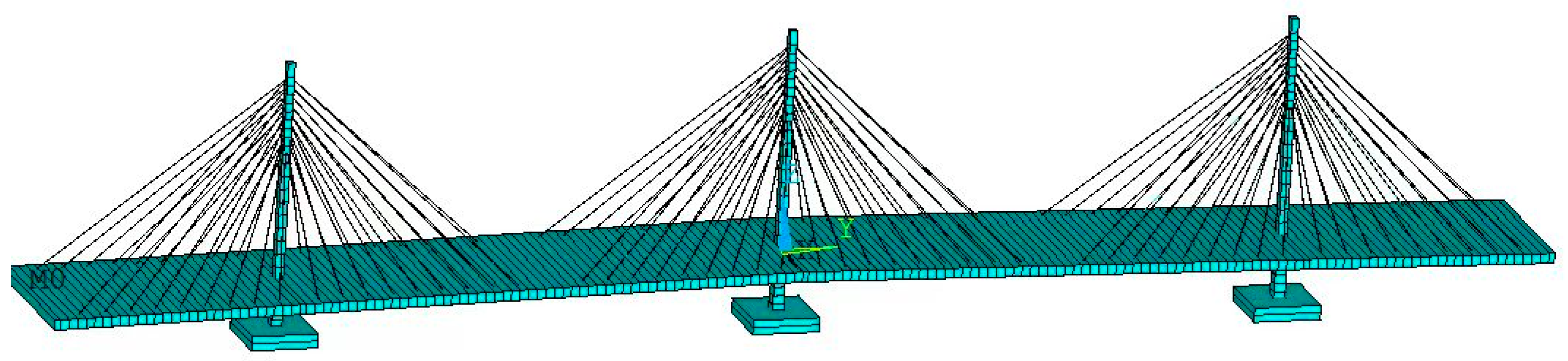
Based on the content, a finite element model of the cable-stayed bridge was established. The coordinate origin is set at the midpoint of the main span, with the x-axis aligned with the transverse direction of the main girder, the y-axis with the longitudinal direction of the main girder, and the z-axis with the vertical direction of the main girder. In this paper, the positive direction of the x-axis is defined as upstream, and the negative direction of the x-axis as downstream. The positive direction of the z-axis is vertically upward. Nodes that are not shared are positioned at the intersection of the tower and girder lines to achieve a floating system with fixed tower–pier connections and separated tower–girder connections. The basic finite element model of the cable-stayed bridge constrains both ends in the z-direction while releasing other degrees of freedom. The lower part of the tower column is fully constrained, and the basic finite element model of the cable-stayed bridge is depicted in
Figure 2.
4. Analysis of Cable Damage
4.1. Cable Damage Model
The stay cables are typically composed of high-strength steel wire strands (steel strand bundles) and an external protective system. Internally, the cable usually consists of several individual wires grouped in various configurations. The material discrepancies in steel wires significantly impact their respective strengths, thereby complicating the task of ensuring uniform initial stresses across each wire. Consequently, the tensile force exerted on the cable cannot be uniformly distributed among the individual wires composing the cable. When the tensile force applied to the cable becomes sufficiently large, the steel wire experiencing the maximum stress and the minimum strength within the cable will break first, causing the cable’s tensile load-bearing capacity to begin to diminish [
13]. However, in practical research, the differences in the parameters of the steel wires within the cable are often overlooked, and the cable is composed of several parallel bundles of steel wire fibers. Therefore, the strength of the cable can be studied using the fiber bundle strength calculation theory. When applying the fiber bundle strength theory, the cable can be simplified into a series–parallel model [
14,
15], where the entire cable is considered to be composed of individual steel wires in parallel, and each steel wire is made up of several units connected in series. The strength of the cable is determined by the combined strength of all the steel wires inside it. The actual strength of the cable is directly correlated with the quantity of steel wires it contains, a phenomenon referred to as the Daniels effect [
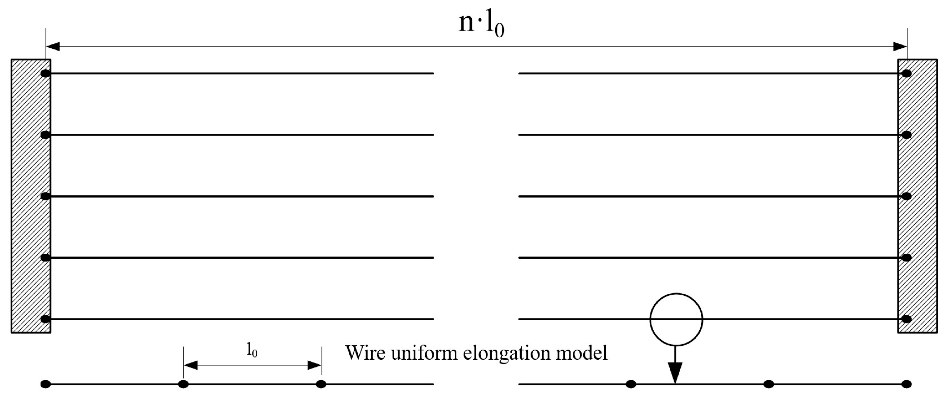
16]. The entire stay cable is considered to be composed of individual steel wires connected in parallel, with each steel wire consisting of several units connected in series, as shown in
Figure 3. The strength of the stay cable is determined by all the internal steel wires, and the actual strength of the cable depends on the number of steel wires within it [
17].
Under the assumption of the Daniels [
16] effect, the mechanical properties of the cable are entirely determined by the strength, stiffness, and other characteristics of each individual wire. If the elastic modulus of each parallel steel wire is the same, the stress they bear will also be identical [
15]. When a stay cable is damaged, the structural damage can be equivalently represented by the fracture of steel wires. The strength of the damaged cable is determined by the number of remaining wire bundles, that is, the remaining effective cross-sectional area of the cable.
4.2. Cable Damage Simulation
Cable damage simulation is commonly carried out using methods such as the area reduction method, elastic modulus reduction method, reverse load method, and solid element method. The breakage of the steel wires in the cable can be considered as a reduction in its effective cross-sectional area, making the area reduction method easier to understand. The area reduction method refers to expressing the degree of damage to the cable through the reduction in its cross-sectional area. When a cable sustains damage, its mechanical properties are altered. It is assumed that the elastic modulus of the steel wires remains constant before and after the damage, and the cable’s damage is considered a decrease in the effective cross-sectional area. Various levels of damage are indicated by the reduction in this area. Assume that the force-bearing area of the cable in an undamaged state is A, and the effective force-bearing area after damage is A*. The degree of cable damage is represented by the variable D.
D = 0 means that the cable is undamaged. D = 1 means that the cable is completely broken. When 0 < D < 1, it means that the cable is in various degrees of damage.
In finite element analysis, the damage to the stay cable is realized by reducing the cable area. To simulate the damage occurring in the cable under initial stress conditions, this paper employs the method of birth and death elements. Utilizing the finite element model of the undamaged cable-stayed bridge, two elements are positioned at the pre-determined simulated cable damage location to collectively support the load in that section of the cable. On the premise that the two elements can substitute the original cable element, their attributes are assigned based on different damage levels to ensure that the initial stress remains the same. By deactivating one of the elements in subsequent calculations, cable damage is simulated, thereby modeling the cable damage under operating conditions.
5. Analysis of the Impact of Cable Damage on Static Performance
When a cable is damaged, the structure undergoes a redistribution of internal forces, and the remaining cables, towers, and main girder reach a new equilibrium after this redistribution [
8,
9,
18]. Due to the symmetrical nature of the cable-stayed bridge structure and the symmetrical arrangement of the cables, one-quarter of the cables in the entire bridge were selected for simulation. The changes in the cable forces, main girder alignment, and main tower displacement were analyzed under six damage scenarios: cross-sectional area losses of 10%, 20%, 30%, 50%, 80%, and complete cable failure.
5.1. Impact of Single-Cable Damage on Static Performance
To investigate the impact of single-cable damage on the static performance, 27 cables numbered from 1-S9 to 1-S1, 1-M1 to 1-M9, and 2-M9a to 2-M1a were selected for damage analysis. Six damage scenarios were simulated, corresponding to cross-sectional area losses of 10%, 20%, 30%, 50%, 80%, and complete cable rupture, to study the variations in cable forces throughout the entire bridge.
5.1.1. Impact on Cable Force
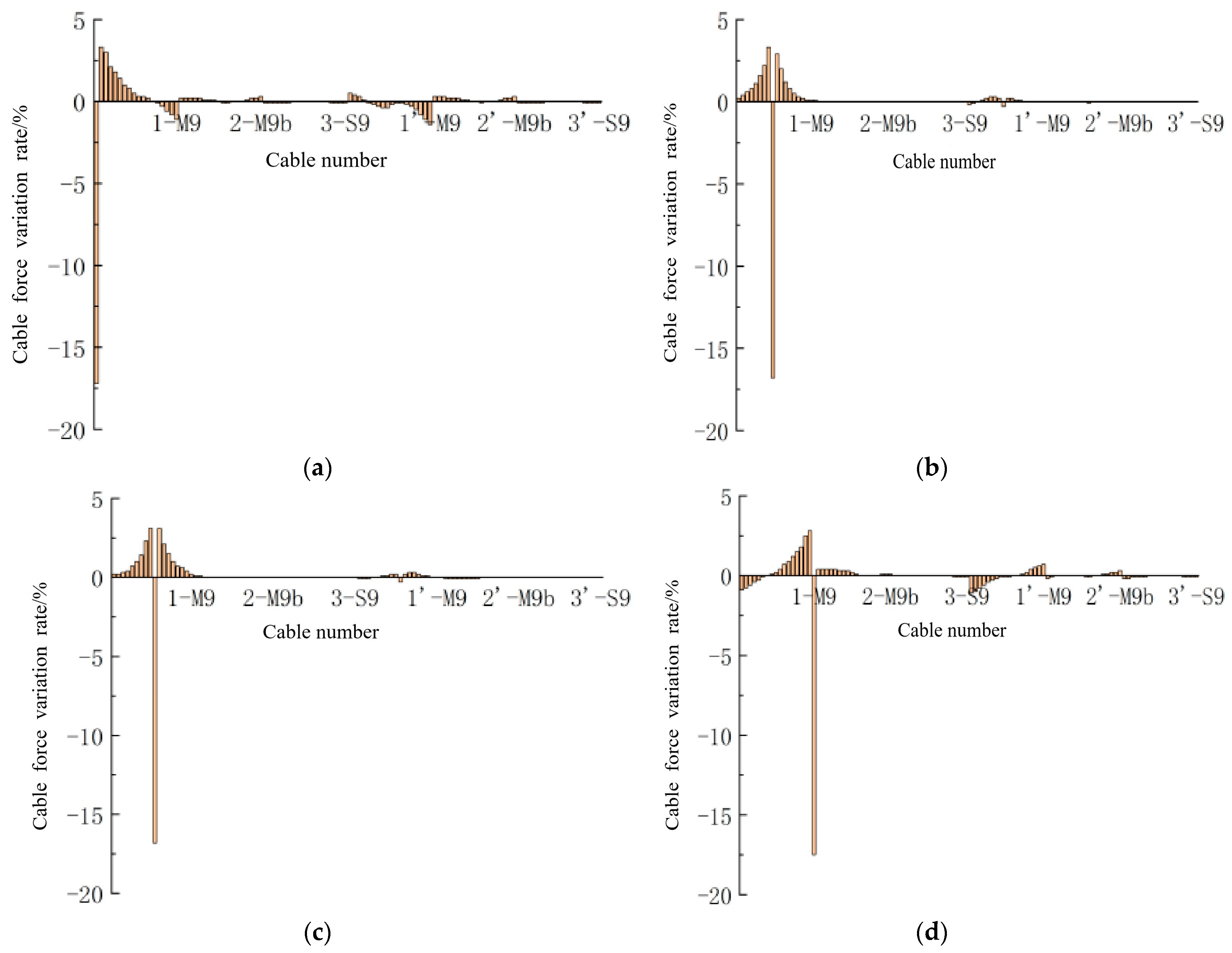
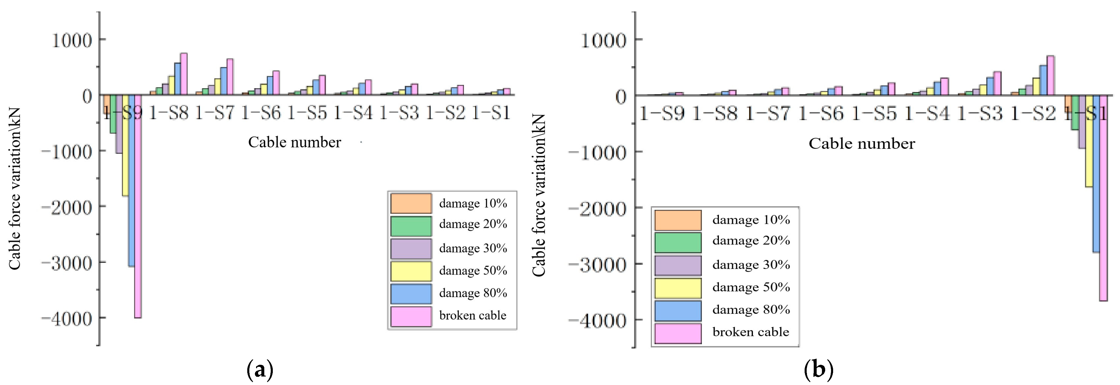
The long cable 1-S9 in the side span, the long cable 1-M9 in the mid-span, the short cable 1-S1 in the side span, and the short cable 1-M1 in the mid-span were selected as representative long and short cables, respectively. The changes in cable forces across the entire bridge under the scenario of a 20% cross-sectional area loss for these typical cables are shown in
Figure 4. In the figure, the vertical axis represents the rate of change in cable force before and after damage, with negative values indicating a decrease in cable force and positive values indicating an increase in cable force. The horizontal axis represents the numbering of the cables across the entire bridge.
As shown in
Figure 4, after the cable damage, the peak value of the cable force variation rate is located at the damage site. When the damage area of cables 1-S9, 1-S1, 1-M1, and 1-M9 reaches 20%, the variation rates of the cable forces at the damaged locations are −17.2%, −16.8%, −16.8%, and −17.5%, respectively, which are close to damage levels. At the same time, the influence of cable damage at the corresponding positions of the edge span and mid-span on the cable forces is generally the same, consistent with the aforementioned pattern of cable damage affecting the cable forces.
While the cable forces near the damaged cable increase, the closer the position on the same side of the cable plane to the damaged cable, the more significant the change in cable force. In the four damage scenarios depicted in
Figure 4, peaks in cable force increments are observed near the cable damage locations, with values of 3.3%, 3.3%, 3.1%, and 2.8%, respectively. The peak increments in cable forces at various damaged locations are similar. Moreover, cable damage significantly affects the cables on the opposite side of the same bridge tower. The further the cable anchorage position on the opposite side is from the bridge tower, the more pronounced the variation in cable forces becomes.
The impact of cable damage on the structure varies with the length of the cable. Damage to long cables has a more significant impact on the overall bridge cable forces and affects a larger area. This impact is not only observed near the damaged location but also extends to the cable forces on the laterally symmetric cable surfaces. The influence follows the same trend as the variation in cable force on the damaged cable surface, although the effect is relatively smaller. Damage to short cables primarily affects the cable forces near the damage location, with a less noticeable variation in overall bridge cable forces compared to the damage to long cables.
Considering the influence of different damage degrees on the cable force, the effect of cable damage on the cable force is primarily reflected on the same side of the bridge tower as the damaged cable. Therefore, the analysis of the influence of different damage degrees on the cable force can focus on the key cables. Select the typical cables 1-S9 and 1-S1 and simulate the loss of cable area under six working conditions: 10%, 20%, 30%, 50%, 80%, and no loss. The study focuses on the changes in the cable forces of cables 1-S9 to 1-S1 under varying degrees of damage, as shown in
Figure 5.
As illustrated in
Figure 5, the trend of the influence of various damage levels on the cable forces of the entire bridge is essentially consistent [
4,
19,
20]. The impact of cable damage on cable forces gradually intensifies with the extent of the damage. This impact is primarily evident on the same side cable plane of the tower where the damaged cable is located, with the peak reduction in cable force consistently occurring at the site of the damage. For the long cable 1-S9 in the side span, under the six damage scenarios, the change rates of its cable force are −8.4%, −17.2%, −26.2%, −45.3%, −76.8%, and −100.0%. The change rates of the cable force for the short cable 1-S1 in the side span under six damage conditions are −8.2%, −16.8%, −25.7%, −44.6%, −76.2%, and −100.0%, respectively. The changes in cable forces near the damaged cable also increase, and the magnitude of these changes becomes more pronounced as the degree of damage increases. The trends in cable force changes are identical across different damage levels.
5.1.2. Impact on Main Beam Alignment
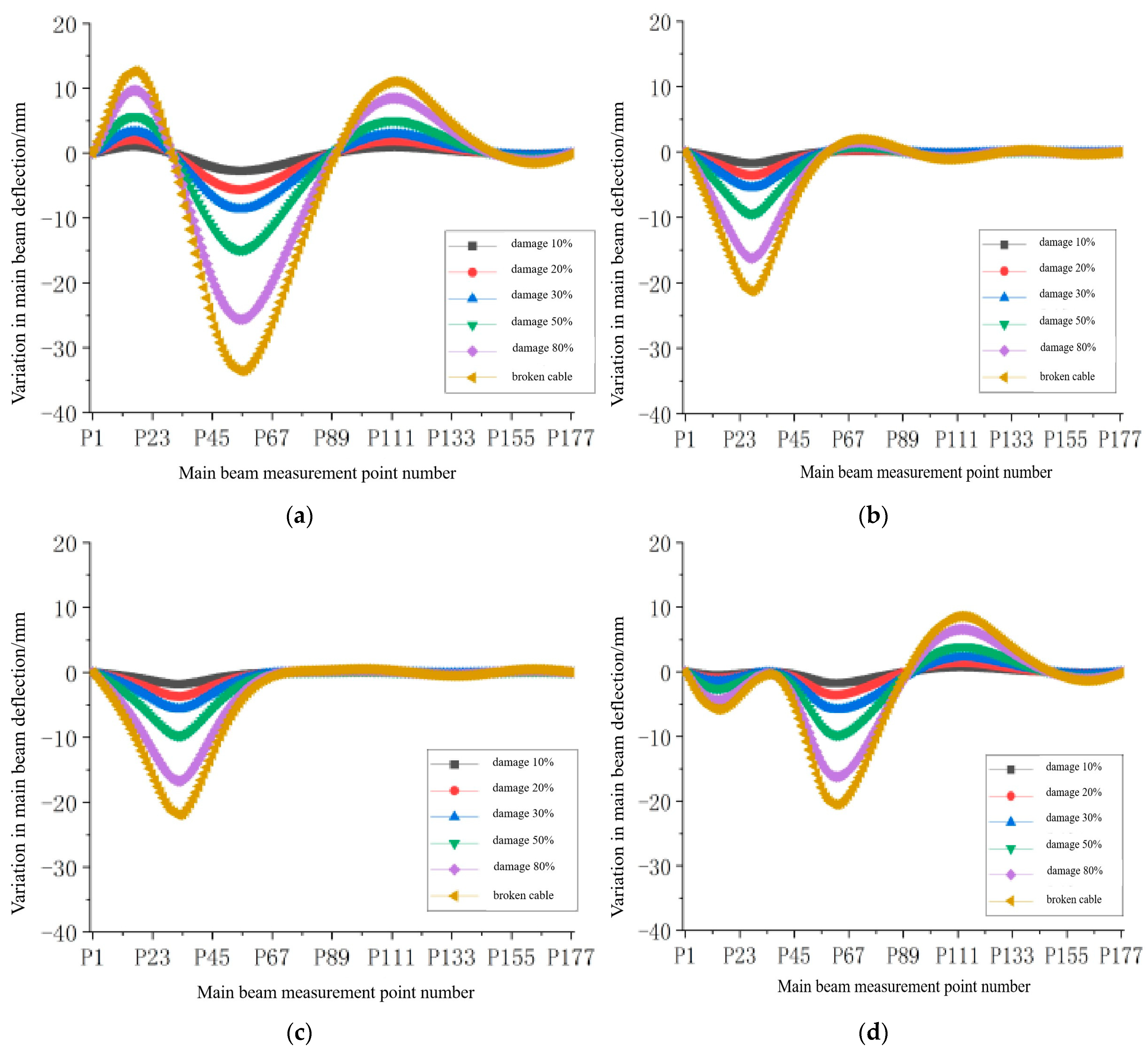
The long cable 1-S9 in the side span, the long cable 1-M9 in the mid-span, the short cable 1-S1 in the side span, and the short cable 1-M1 in the mid-span were selected as representative long and short cables, respectively. The deflection changes in the main girder of the entire bridge under six damage scenarios are shown in
Figure 6. In the figure, the vertical axis represents the deflection change values of the main girder nodes, where negative values indicate downward deflection (sinking), and positive values indicate upward deflection (lifting) of the main girder nodes. The horizontal axis represents the longitudinal positions of the measuring points along the main girder.
From
Figure 6, it can be observed that damage at different locations has varying effects on the alignment of the main girder [
11,
12,
13]. When the long cable 1-S9 in the side span is damaged, the displacement of the main girder is somewhat restricted due to the proximity of the damaged cable to the abutment. At this juncture, as the cable force near the damaged cable intensifies, the nodes of the main girder display an upward deflection trend. On the opposite side of the damaged cable, the cable force diminishes, leading to a downward deflection trend in the main girder. A peak deflection change occurs at the 1/3 span position on the same side as the damaged cable (near the mid-span of the main span). When the long cable 1-M9 in the mid-span is damaged, the nearby nodes of the main girder experience downward deflection, with a peak occurring at the 1/3 span position on the same side as the damaged cable. On the opposite side of the damaged cable, despite the increase in cable tension causing an upward deflection trend at the nodes, the overall nodes still exhibit downward deflection due to the general sinking of the structure. Furthermore, the impact of damage to the long cable in the side span on the deflection of the main girder is more pronounced compared to damage to the long cable in mid-span.
When the short cable 1-S1 in the side span is damaged, its cable force decreases, causing the anchoring point of the main girder to sink. Meanwhile, the cable force near the damaged cable increases, leading to an upward deflection trend at the nodes of the main girder. However, due to the more significant sinking near the anchoring point of the damaged cable, the surrounding area experiences an overall downward deflection. The peak deflection change occurs near the anchoring point of the damaged cable, while the deflection change in the main girder is mainly observed in the half-span bridge on the same side as the damaged cable. When the short cable 1-M1 in the mid-span is damaged, the trend of deflection change is like that of the short cable in the side span, with the peak change also occurring near the anchoring point of the damaged cable.
Under different damage levels, the deflection change pattern of the main girder remains consistent. As the degree of damage increases, the magnitude of the deflection change also becomes larger. The peak of deflection variation always occurs near the anchorage point of the damaged cable or at one-third of the span on the same side as the damaged cable.
Under the same degree of damage, the effect of long-cable damage on the deflection of the main beam is more significant compared to that of short-cable damage. The impact on deflection is reflected in the overall deflection of the bridge, and as the degree of damage increases, the rate of change in deflection becomes more pronounced. The effect of short-cable damage on deflection is primarily seen in the downward deflection of nodes near the damaged area, with little effect on the deflection of undamaged main beam segments. Even as the damage escalates, its impact continues to be negligible.
5.1.3. Effects on the Displacement of the Main Tower
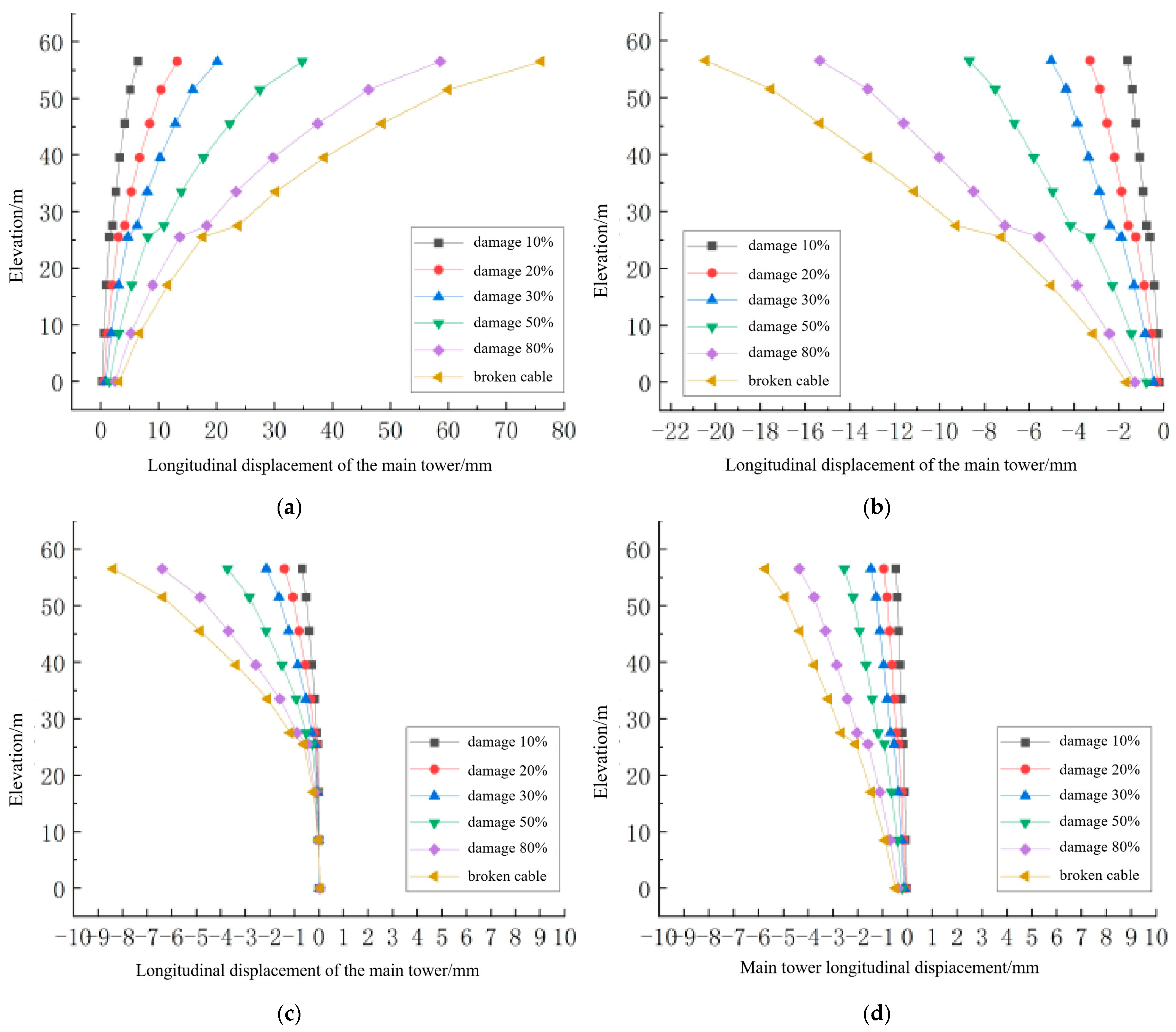
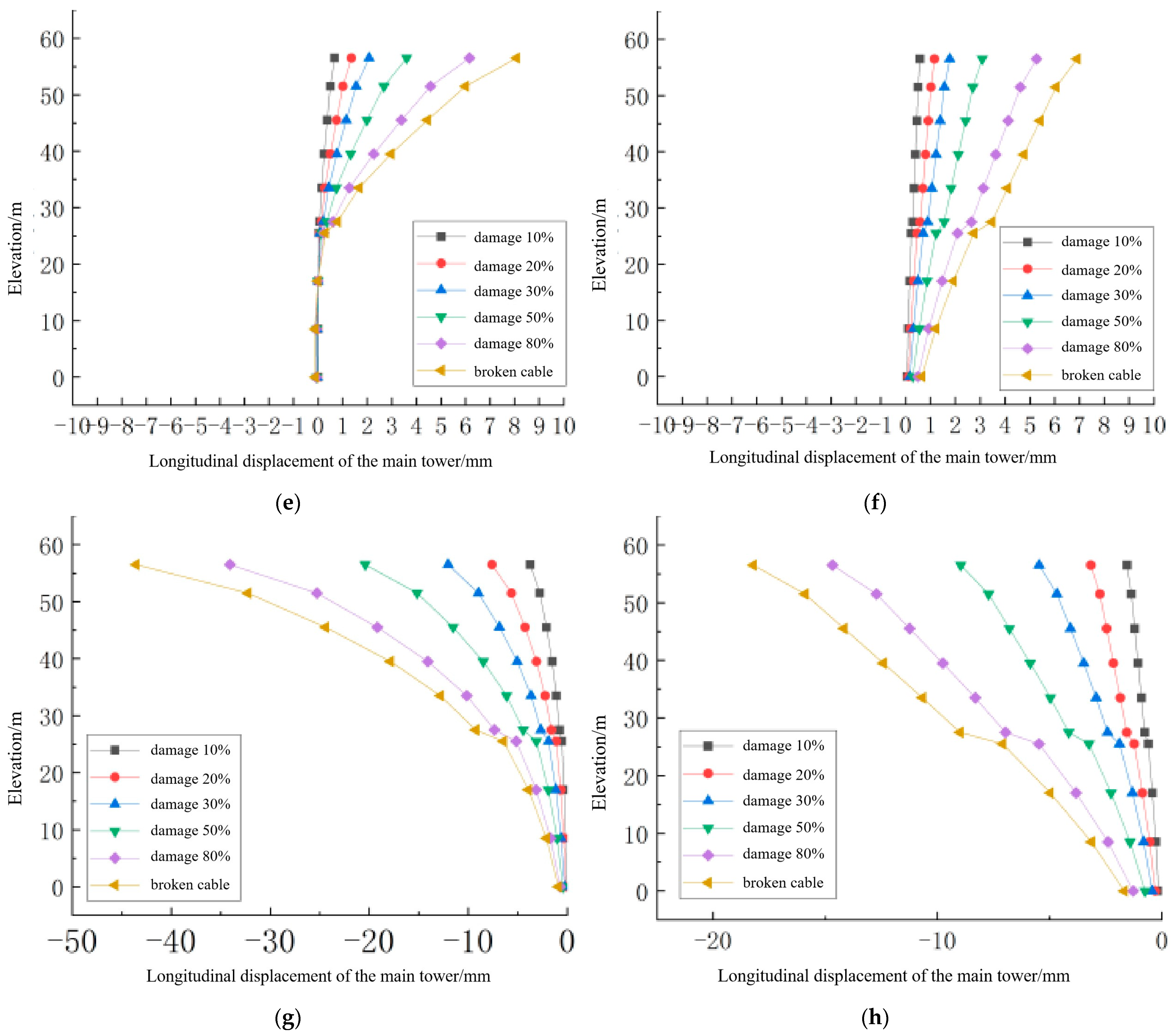
The long cable 1-S9 in the side span, the long cable 1-M9 in the mid-span, the short cable 1-S1 in the side span, and the short cable 1-M1 in the mid-span were selected as typical long and short cables, respectively. The longitudinal displacement changes in the side tower and the middle tower under six damage scenarios are shown in
Figure 7. In the figure, when the horizontal displacement of the main tower is negative, it indicates that the tower deforms toward the side span. The displacement change value is the difference between the longitudinal displacement of the main tower after cable damage and the displacement under undamaged conditions.
When the long cable 1-S9 in the side span and the long cable 1-M9 in the mid-span are damaged, due to the loss of cable tension, the side tower shifts away from the damaged cable, while the middle tower shifts toward the side of the damaged cable because of the increased tension on the closer side. When the short cable 1-S1 in the side span and the short cable 1-M1 in the mid-span are damaged, although the loss of cable force is relatively small, the increase in cable force on the same side of the cable plane results in an overall greater cable force on the same side compared to the opposite side. Consequently, the side tower shifts toward the side of the damaged cable, and similarly, the middle tower shifts toward the side of the damaged cable due to the increase in cable force on the side closer to the damaged cable. Furthermore, the magnitude of the displacement changes in the bridge towers after cable damage is related to the location distribution of the damaged cables.
At the same time, the magnitude of the displacement changes in the bridge tower after cable damage is related to the location distribution of the damaged cables. Since the anchoring points of the long cables are located at the cantilever end of the main girder, they have a more sensitive impact on the displacement of the main tower. Therefore, the effect of long-cable damage on the longitudinal displacement change in the main tower is more pronounced compared to short-cable damage [
21].
As the extent of damage increases, the impact of cable damage on the longitudinal displacement of the main tower becomes more pronounced. Among them, the damage to the side span long cable 1-S9 has the greatest overall impact on the longitudinal displacement of the side tower. In six damage scenarios, with damage levels of 10%, 20%, 30%, 50%, 80%, and cable breakage, the peak longitudinal displacements of the side tower under these damage conditions are 6.48 mm, 13.19 mm, 20.14 mm, 34.81 mm, 58.60 mm, and 76.04 mm, respectively.
The damage to the side span long cable 1-S9 and the middle span long cable 1-M9 results in more noticeable changes in the longitudinal displacement of the side tower, with a smaller overall impact on the middle tower’s displacement. The reason for this is that the damaged cables are located on the cable plane of the side tower, so their impact is primarily reflected on the side tower.
5.2. Impact of Multiple-Cable Damage on Static Performance
Based on the research, the impact of damage to the long cables in the side span on the structure is more significant. Therefore, when considering the effects of multiple-cable damage on the structure, the primary focus is on analyzing the most critical scenarios involving multiple long cables in the side span. Four damage scenarios have been established: transverse symmetric damage, adjacent cable damage, original symmetric damage, and longitudinal symmetric damage. The specific combinations of these damage scenarios are detailed in
Table 1. Taking the case of 30% cable damage as an example, the changes in cable force, main girder deflection, and main tower displacement are analyzed under these four damage scenario combinations.
5.2.1. Effect on Cable Force
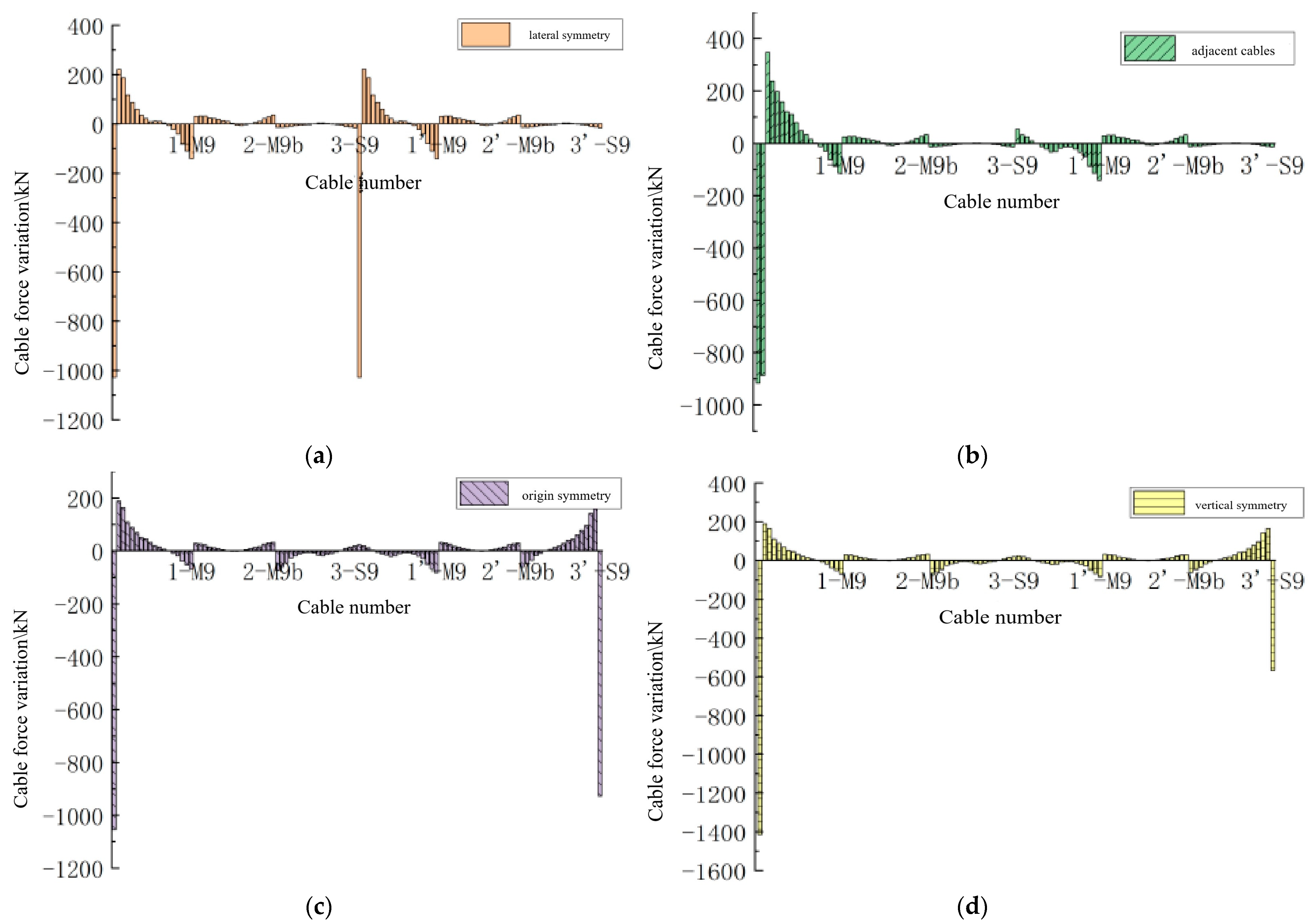
The changes in the cable forces of the entire bridge under the four damage scenarios are shown in
Figure 8. In the figure, the vertical axis represents the change in cable force before and after damage, with negative values indicating a decrease in cable force and positive values indicating an increase. The horizontal axis represents the numbering of the cables across the entire bridge.
As shown in
Figure 8, after multiple cables are damaged, the cable forces undergo redistribution. The force at the damaged cable decreases, while the forces in the cables near the damaged cable increase. On the same side of the cable plane as the damaged cable, the closer the position is to the damaged cable, the more significant the change in cable force. On the opposite side of the cable plane, the farther the cables are from the bridge tower, the more pronounced the change in cable force. This pattern is consistent with the influence of single-cable damage on cable forces.
5.2.2. Effect on Deflection of Main Beams
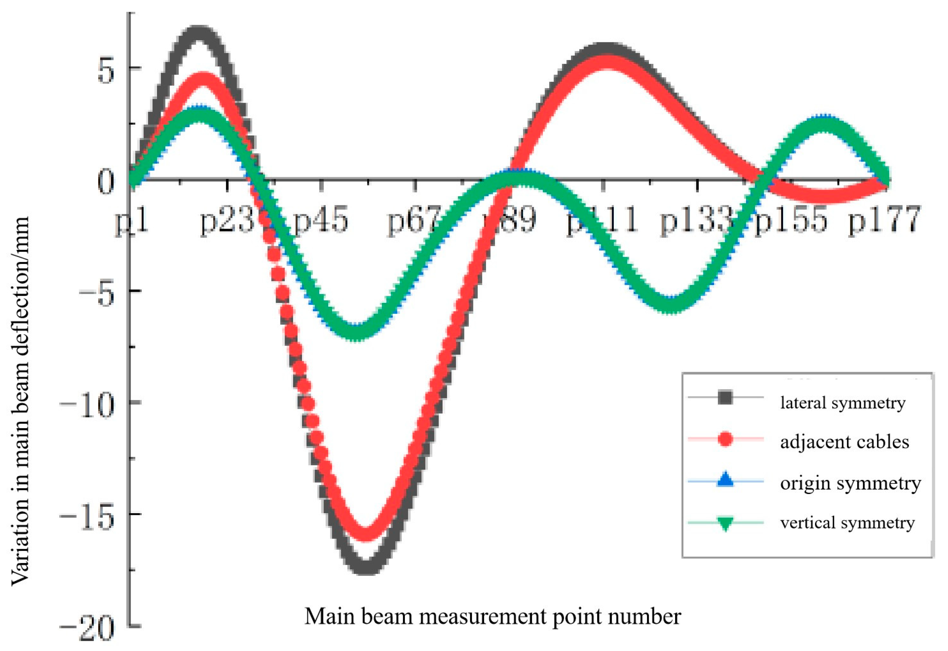
The impact of the four damage scenarios on the deflection of the main girder is shown in
Figure 9.
As shown in
Figure 9, compared to the effect of single-long-cable damage on the deflection of the main girder, the influence of transverse symmetric damage and adjacent cable damage on the deflection is similar, and the trend of deflection change is essentially consistent with that of single-long-cable damage, with a peak deflection change occurring at the 1/3 span. Among these, transverse symmetric damage has the most significant impact on deflection. When transverse symmetric damage (Scenario 1) occurs in the stay cables, the effect on the deflection of the main girder is approximately twice that of single-long-cable damage.
5.2.3. Effects on the Displacement of the Main Tower
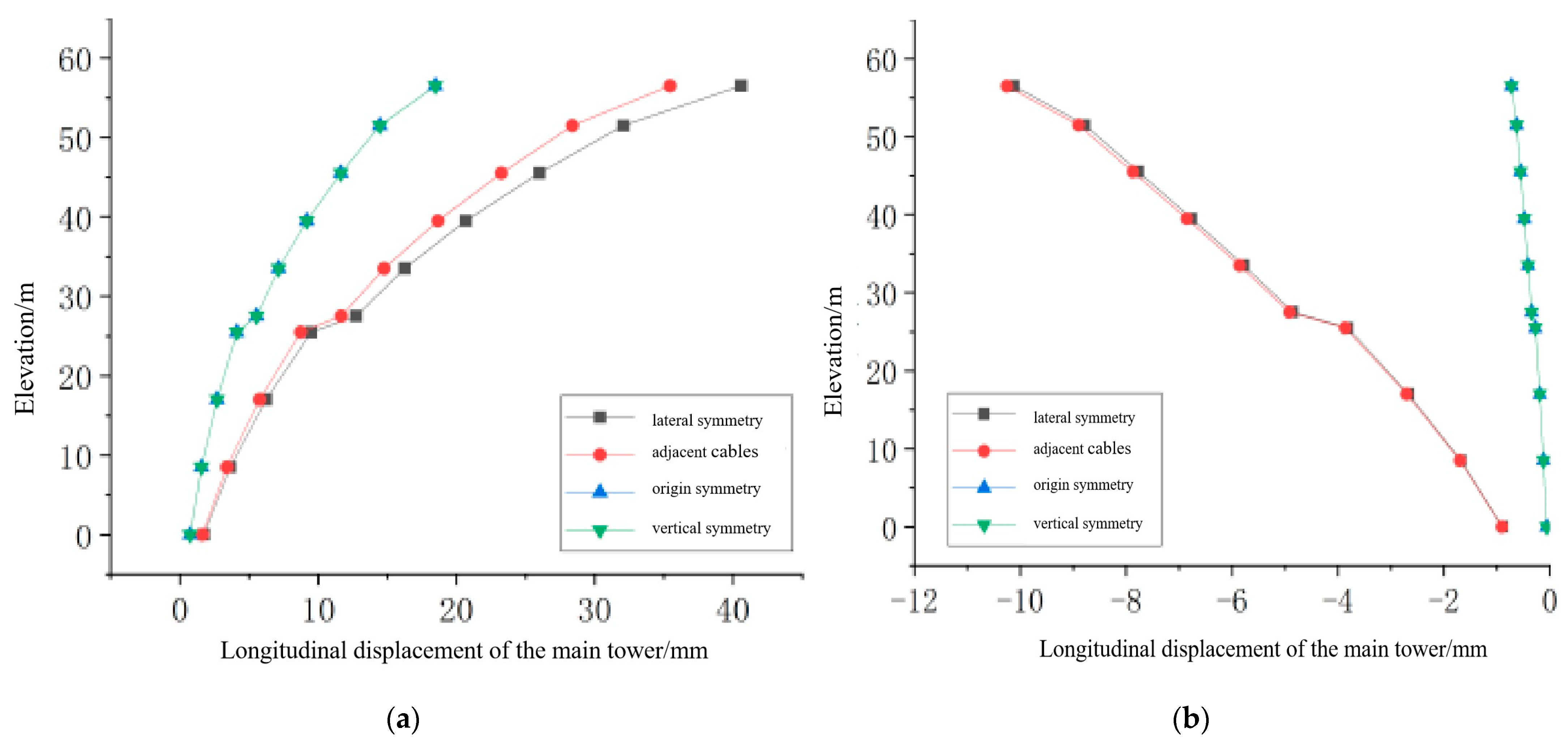
The impact of the four damage scenarios on the displacement of the main tower is shown in
Figure 10.
As shown in
Figure 10, compared to the effect of damage to a single long cable on the displacement of the main tower, the trend of displacement change due to damage to multiple cables is similar. Among them, the impact of lateral symmetric damage and adjacent cable damage on the displacement of the main tower is significantly greater than that of damage to a single cable, and the effects of the two on the main tower displacement are almost identical. The impact of longitudinal symmetric damage and original symmetric damage on the displacement of the main tower is basically the same, and the effect at the side span position is also close to that of damage to a single long cable on the main tower displacement. Therefore, the cumulative effect of distant symmetric damage on the displacement of the side towers is not significant. At the same time, due to symmetry, the longitudinal displacement of the middle tower cancels out, resulting in no significant change in the longitudinal displacement of the middle tower.
Stay cables connect the main girder and the bridge towers to form an integrated structure. After cable damage occurs, the internal forces and deformations of the main girder and the main tower also change with the variation in cable forces. The change in the force of the damaged cable itself and its impact on the cable forces of the entire bridge determine the deflection changes in the main girder and the displacement of the main towers. By comprehensively considering the influence patterns of single- and multiple-cable damage on the static structural performance, the location and extent of cable damage can be roughly estimated through a combination of these factors. Furthermore, cable replacement schemes can be optimized by analyzing the patterns of damage. For example, considering cable replacement in an original symmetric configuration can minimize the impact on the static performance of the entire bridge, thereby ensuring the safety of the bridge structure.
6. Conclusions
By establishing a finite element model of stay cable damage for a cable-stayed bridge, the influence patterns of different damage locations, damage degrees, and multiple cable damage scenarios on the static and dynamic performance of the cable-stayed bridge are analyzed.
(1) The impact of stay cable damage on the structure becomes more pronounced as the degree of damage increases. The trend of impact on the static performance of the structure remains consistent across varying degrees of damage, with the amplitude increasing as the damage intensifies. The impact on cable force is the most significant, as the redistribution of cable forces following damage primarily reflects the effect of cable damage on the plane where the damaged cable is located. The cable force increases for cables closer to the damage location, whereas it decreases for those farther away, with minimal impact on the remaining cables. The change in cable forces results in variations in the deflection of the main beam and the displacement of the main tower, exhibiting a significant correlation.
(2) Damage to stay cables, varying in position and length, has varying impacts on the performance of the cable-stayed bridge structure. Damage to long cables has a broader impact and greater effect on the structure compared to damage to short cables, exhibiting a distinct compound characteristic. Damage to short cables primarily affects the structure near the damage site, with a relatively minor overall impact, displaying a regional characteristic. Simultaneously, damage to the stay cables in the side spans has a more substantial impact compared to damage to the stay cables in the mid-span.
(3) When multiple stay cables are damaged, the impact on structural performance is like that of single-cable damage. Longitudinally symmetric damage and adjacent stay cable damage render the stay cables in a more precarious condition, and the alterations in the main beam deflection and main tower displacement are also more pronounced. In contrast, origin symmetric damage has a lesser impact on the overall static performance of the bridge.
(4) By comprehensively considering the impact patterns of single- and multiple-stay cable damage on the static structure, it is possible to preliminarily determine the location and extent of stay cable damage in a three-tower cable-stayed bridge. Simultaneously, a cable replacement plan can be devised based on the observed damage patterns. For a three-tower bridge, an original symmetric configuration for the cable replacement is advisable, as it minimally affects the bridge’s overall static performance, thereby ensuring its structural integrity.
Author Contributions
Supervision and Funding acquisition are handled by S.C. Conceptualization and methodology were handled by T.W. The Concept, Methodology, Writing—review & editing are handled by X.C. Concept Investigation, Writing—Original Draft was undertaken by G.H., Y.Z., and Y.Y. All authors have read and agreed to the published version of the manuscript.
Funding
This research received no external funding.
Data Availability Statement
The data presented in this study are available on request from the corresponding author.
Conflicts of Interest
Author Xin Cui is a postdoctoral researcher at the Henan Urban Planning Institute & Corporation. The remaining authors declare that the research was conducted in the absence of any commercial or financial relationships that could be construed as a potential conflict of interest.
References
- Zhan, J.; Chen, H. Analysis of the Mid-span Deflection and Crack Formation Causes of the Main Beam of Extra-long Span Continuous Rigid-frame Bridges. China Foreign Highw. 2005, 25, 56–58. [Google Scholar] [CrossRef]
- Li, S.; Wei, S.; Bao, Y.; Li, H. Condition assessment of cables by pattern recognition of vehicle-induced cable tension ratio. Eng. Struct. 2018, 155, 1–15. [Google Scholar] [CrossRef]
- Sun, S. Study on Damage Synptoms of Cable-Stayed Bridge Model in Laboratory. Master’s Thesis, Northeast Electric Power University, Jilin, China, 2022. [Google Scholar] [CrossRef]
- Zhang, X. Analysis and Model Test Research on the Effect of Cable Damageon the Static and Dynamic Performance of Cable-stayed Bridgewith Twin-Towers and Double Cable Planes. Master’s Thesis, Lanzhou Jiaotong University, Lanzhou, China, 2022. [Google Scholar] [CrossRef]
- Yang, O.; Li, H.; Ou, J.; Li, Q.S. Performance variations of a cable-stayed bridge with damaged cables. Int. J. Struct. Stab. Dyn. 2013, 13, 1–21. [Google Scholar] [CrossRef]
- Wu, S. Design and Damage Analysis of Health Monitoring Oriented Experimental Cable-Stayed Bridge Model. Master’s Thesis, Zhejiang University, Hangzhou, China, 2010. [Google Scholar]
- Zhao, X. Effect Study of Cable Damage to Structural Performance of the Cable-Stayed Bridge. Ph.D. Thesis, Southeast University, Nanjing, China, 2005. [Google Scholar]
- Yang, L.; Huang, Y.; Wang, X. Study on the Impact of Cable Damage on the Dynamic Characteristics of a Certain Cable-stayed Bridge. Spec. Struct. 2012, 29, 66–70. [Google Scholar]
- Xu, J.; Sun, H.H.; Cai, S. Effect of symmetrical broken wires damage on mechanical characteristics of stay cable. J. Sound Vib. 2019, 461, 1–21. [Google Scholar] [CrossRef]
- Junying, G.E.; Mubiao, S.U. Simulation Method for Cable Damage of Cable-Stayed Bridge and Its Effect on Cable Tension and Deflection Distribution. China Acad. Railw. Sci. 2016, 37, 30–37. [Google Scholar]
- Tao, J.; Wang, H.; Fu, Z. Influence Analysis of Stay Cable Damage on Deformation of Main Girder. Domest. Int. Roads 2019, 39, 90–93. [Google Scholar] [CrossRef]
- Sun, Q.; Zhang, K. The Impact Analysis of Cable Damage on the Static Performance of Cable-Stayed Bridge. Highw. Eng. 2016, 41, 35–39. [Google Scholar]
- Zhang, Z.; Du, Z.; Yin, C. Analysis of Cable Damage Caused by Fire and Simulation of Cable Replacement Calculation. J. Shijiazhuang Tiedao Univ. (Nat. Sci. Ed.) 2011, 24, 12–15. [Google Scholar] [CrossRef]
- Bolotin, V.V. Initial Flaws Distribution and Size Effect of Fatigue Fracture; IABSE Workshop El Paular: Madrid, Spain, 1992; pp. 75–88. [Google Scholar]
- Faber, M.H.; Engelund, S.; Rackwitz, R. Aspects of parallel wire cable reliability. Struct. Saf. 2003, 25, 201–225. [Google Scholar] [CrossRef]
- Daniels, H.E. The Maximum Size of a Closed Epidemic. Adv. Appl. Probab. 1974, 6, 607–621. [Google Scholar] [CrossRef]
- Weibull, A. Statistical theory of the Strength of Materials. Ing. Vetensk. Akad. Handl. (R. Swed. Inst. Eng. Research Proc.) 1939, 151, 5–45. [Google Scholar] [CrossRef]
- Xing, X.; Liu, S.; Qin, H.; Dang, H. Condition Analysis and Damage Identification for Cable Damage of Cable-stayed Bridge. Sci. Technol. Eng. 2021, 21, 2055–2060. [Google Scholar]
- Zhang, Y. A Study on the Influence of Cable Damageon the Structure Performance of Thecable-Stayed Bridge. Master’s Thesis, Chongqing Jiaotong University, Chongqing, China, 2015. [Google Scholar]
- Liu, H. The Impact of the Change of Main Beam Deflection with Cable-Stayed Bridge Cable Damage. Master’s Thesis, Shijiazhuang Railway University, Shijiazhuang, China, 2017. [Google Scholar]
- Ma, Y.F.; Li, Z.; Peng, A.Y.; Wang, L.; Zhang, J.R. Vulnerability evaluation of cable stayed bridge considering cable damage. J. Chang. Univ. (Nat. Sci. Ed.) 2022, 42, 101–109. [Google Scholar] [CrossRef]
| Disclaimer/Publisher’s Note: The statements, opinions and data contained in all publications are solely those of the individual author(s) and contributor(s) and not of MDPI and/or the editor(s). MDPI and/or the editor(s) disclaim responsibility for any injury to people or property resulting from any ideas, methods, instructions or products referred to in the content. |
© 2025 by the authors. Licensee MDPI, Basel, Switzerland. This article is an open access article distributed under the terms and conditions of the Creative Commons Attribution (CC BY) license (https://creativecommons.org/licenses/by/4.0/).


