
Dynamic Behavior of Lighting GFRP Pole Under Impact Loading


 ,
,
Abstract
1. Introduction
2. Finite Element Analysis
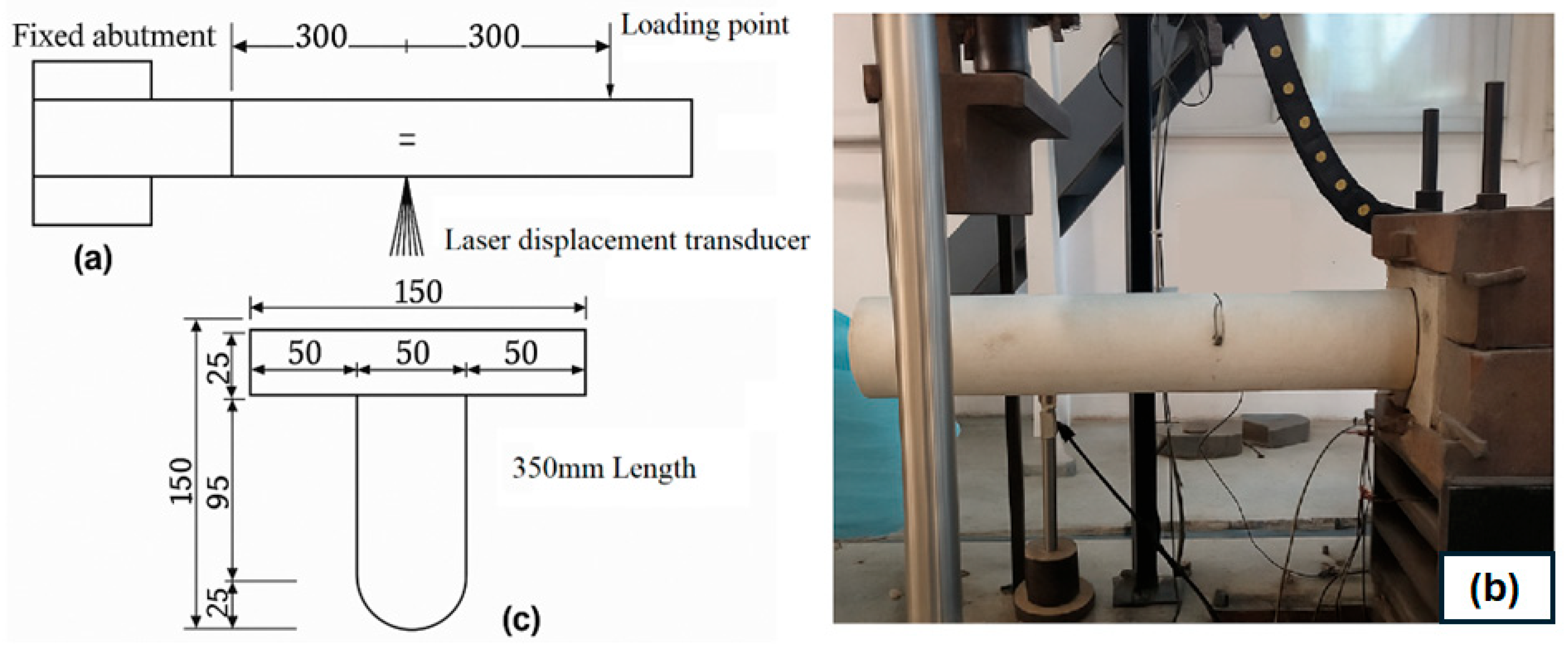
2.1. Validation Model
2.2. Validation Results
2.3. Parametric Studies
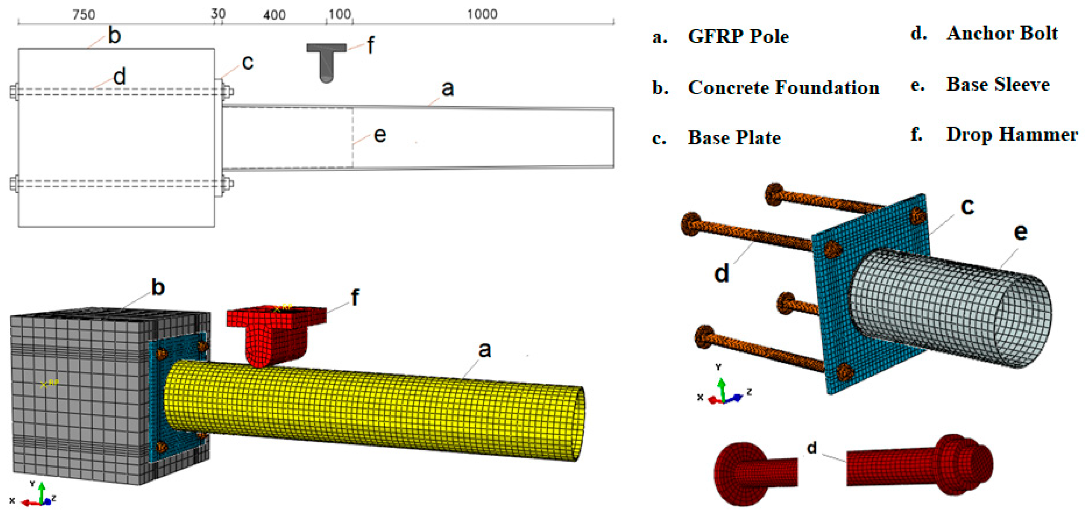
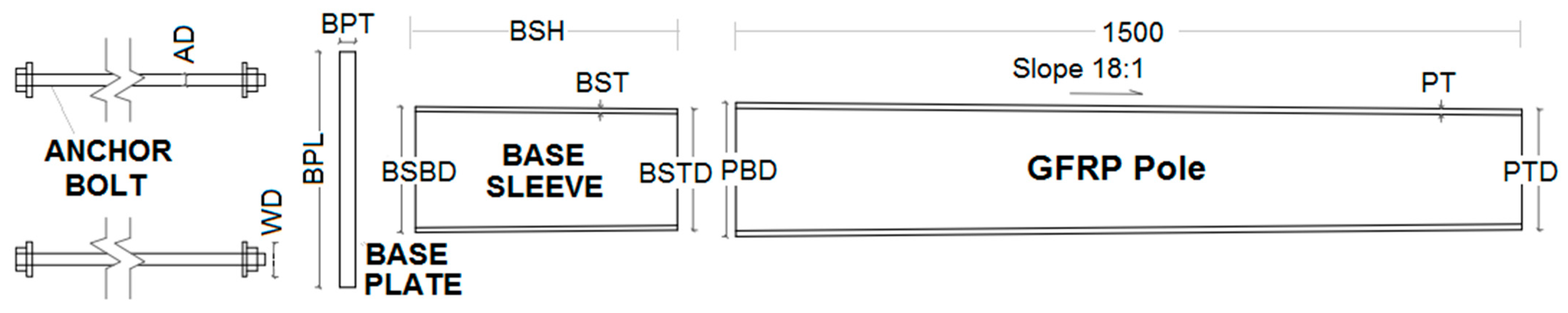
2.3.1. FE Models Geometry
2.3.2. Element Types, Meshing, and Material Properties
2.3.3. Interaction Properties
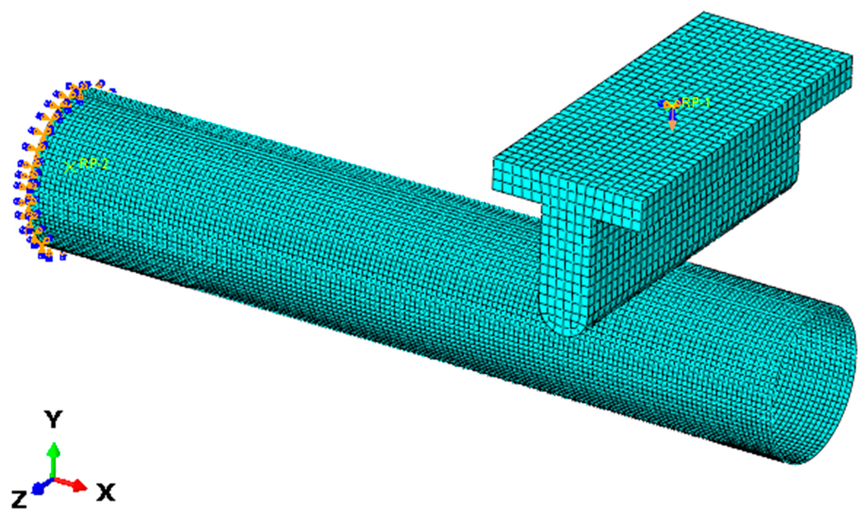
2.3.4. Loading and Boundary Conditions
3. FE Analysis and Discussions
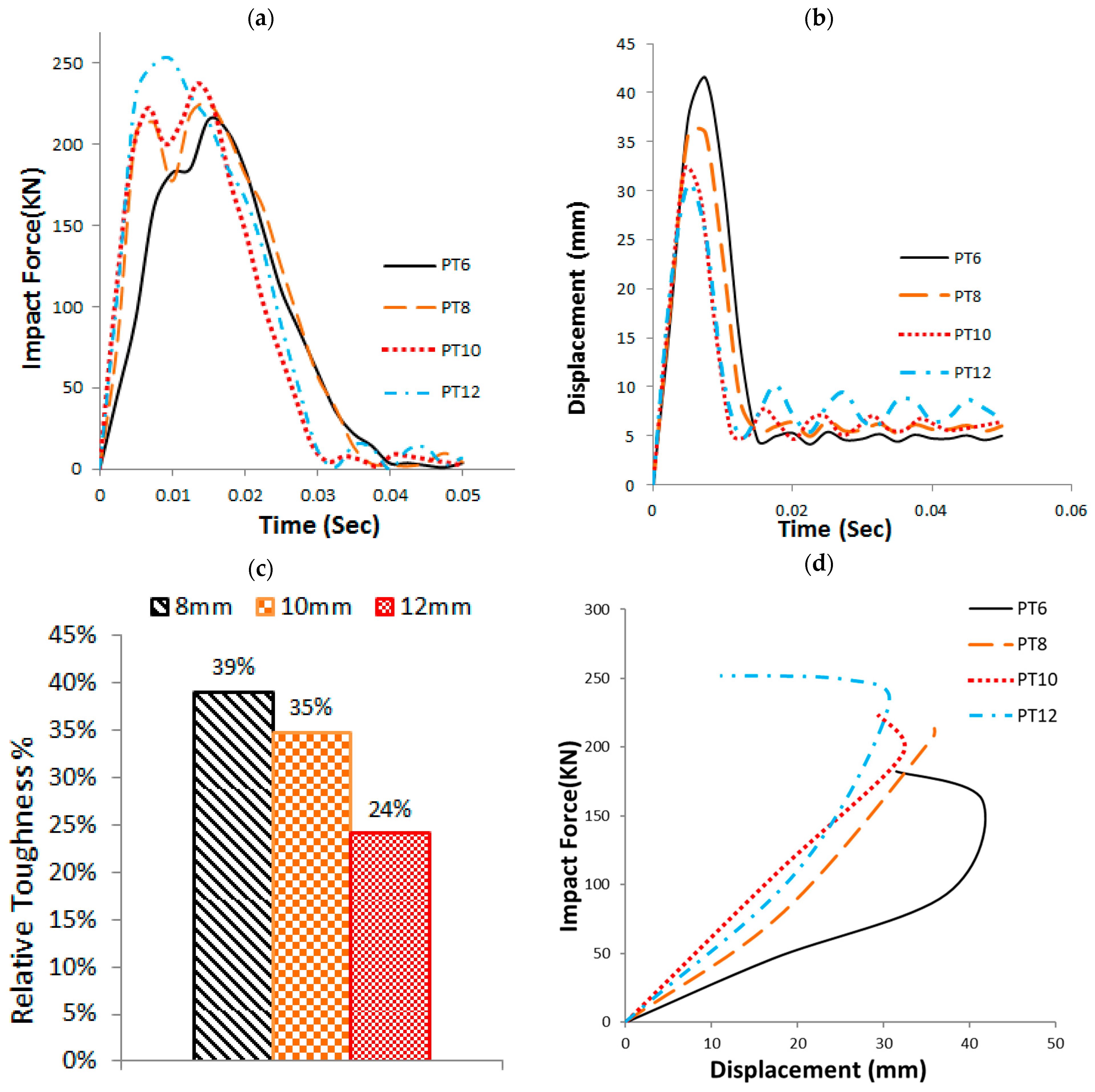
3.1. GFRP Pole Wall Thickness (PT)
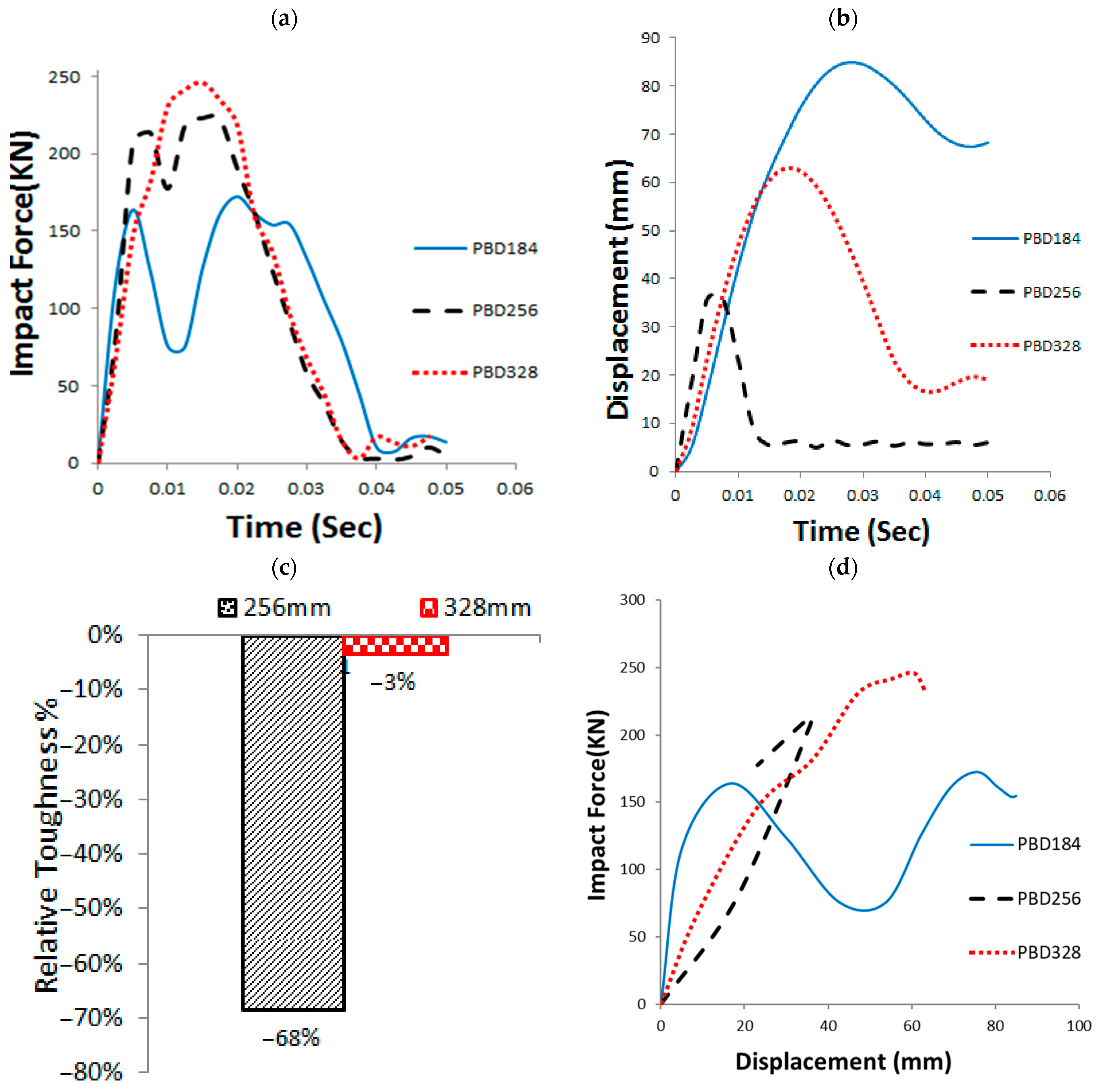
3.2. GFRP Pole Diameter (PBD)
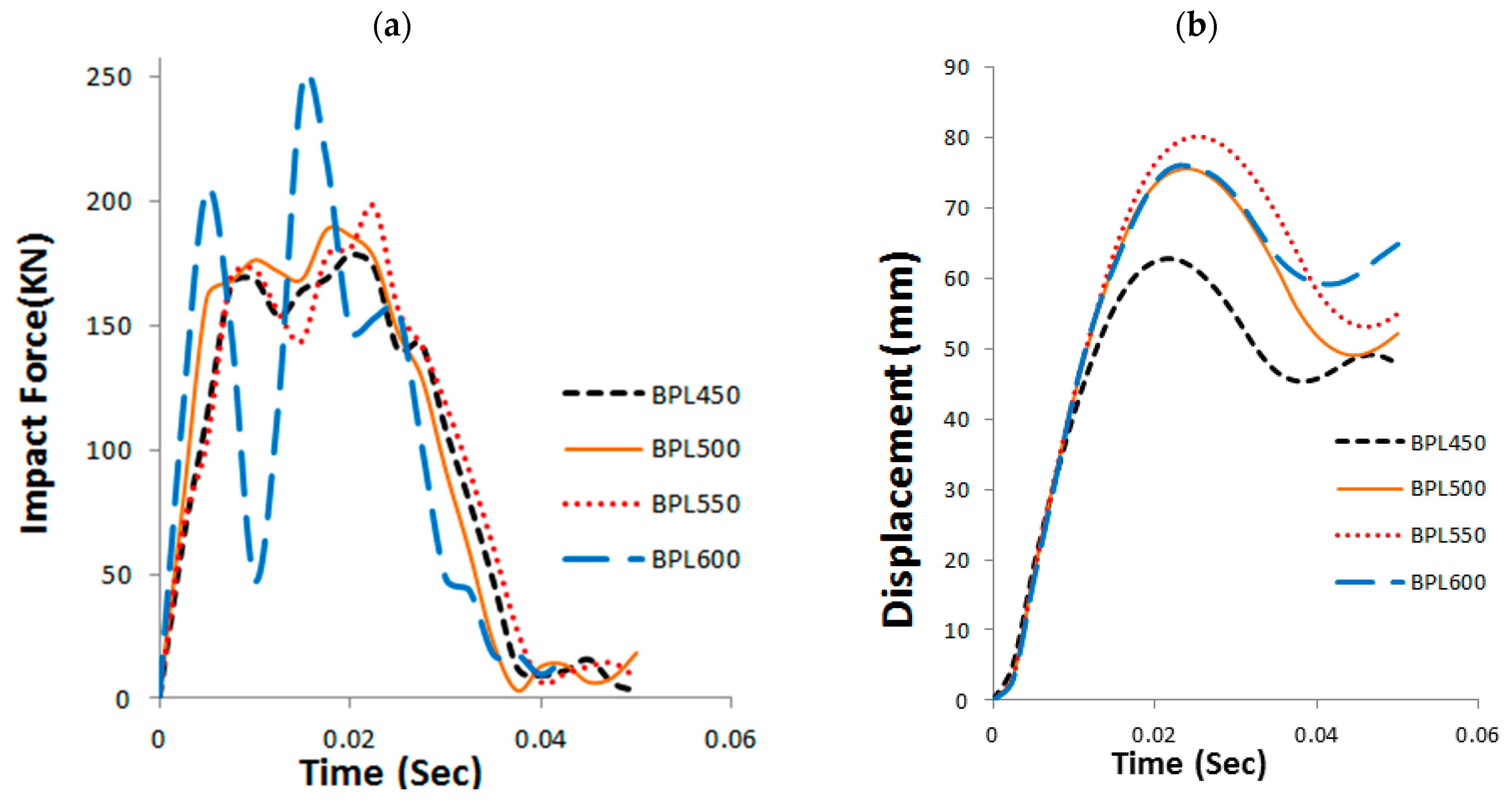
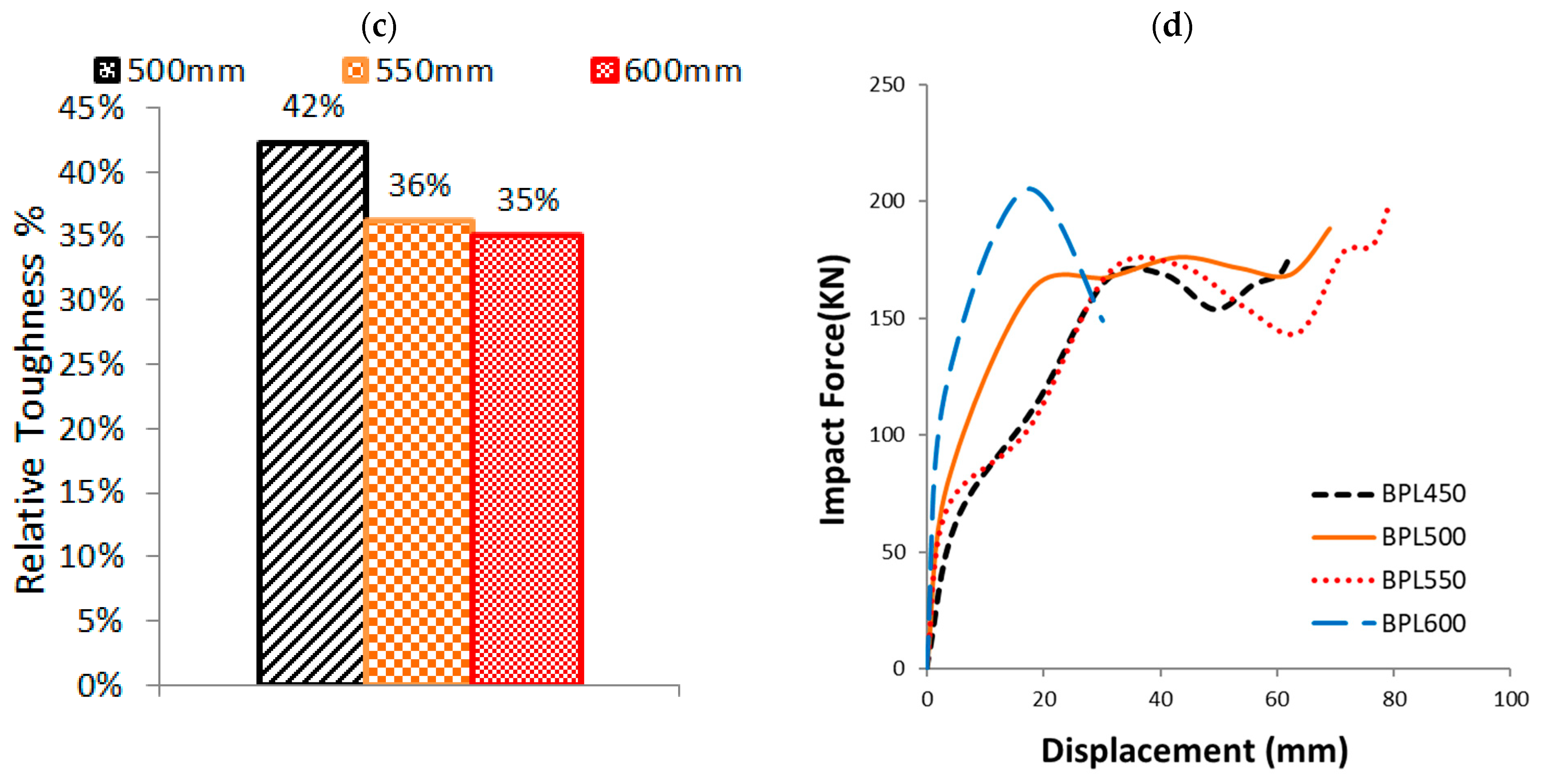
3.3. Base Plate Dimensions (L and B)
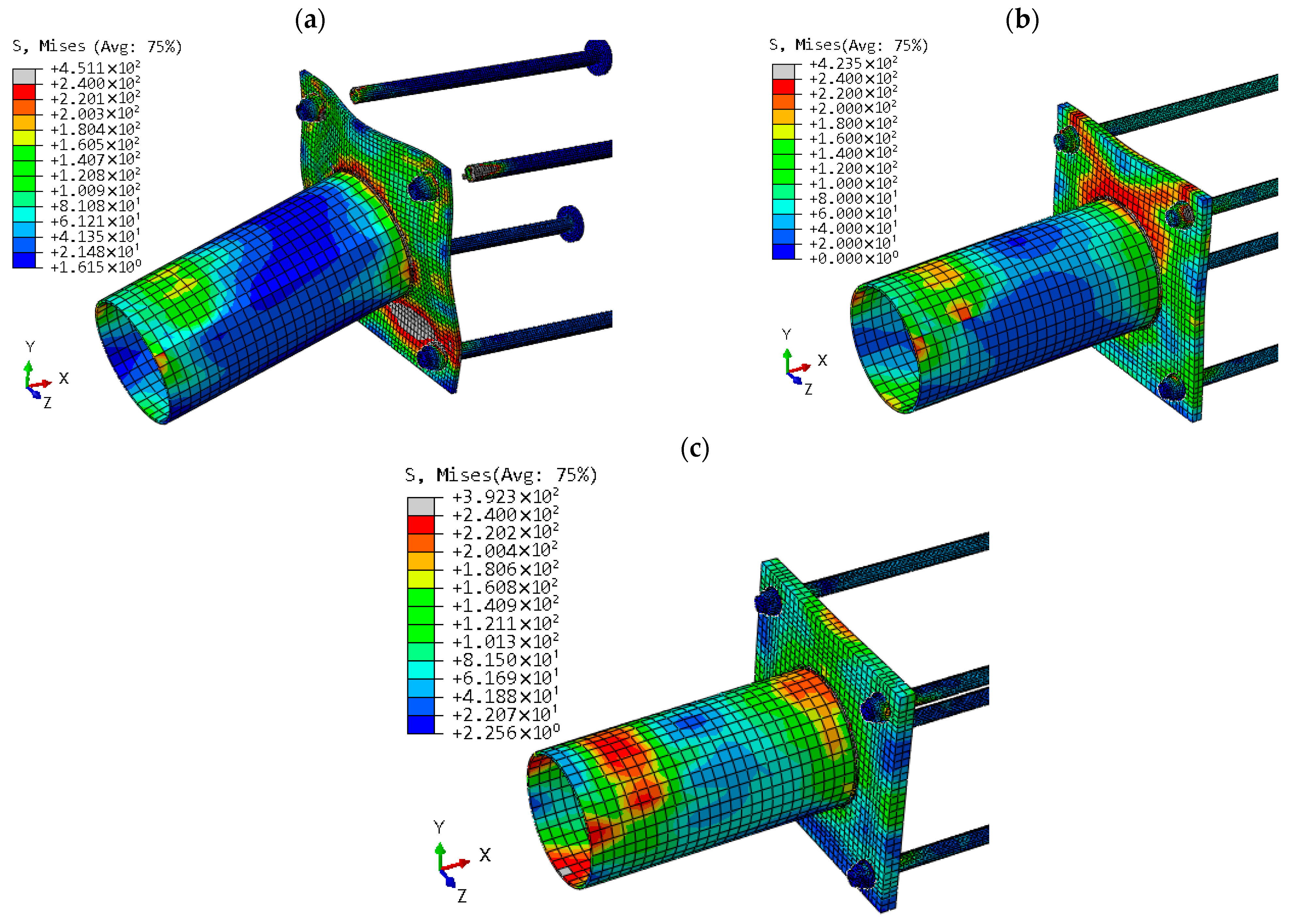
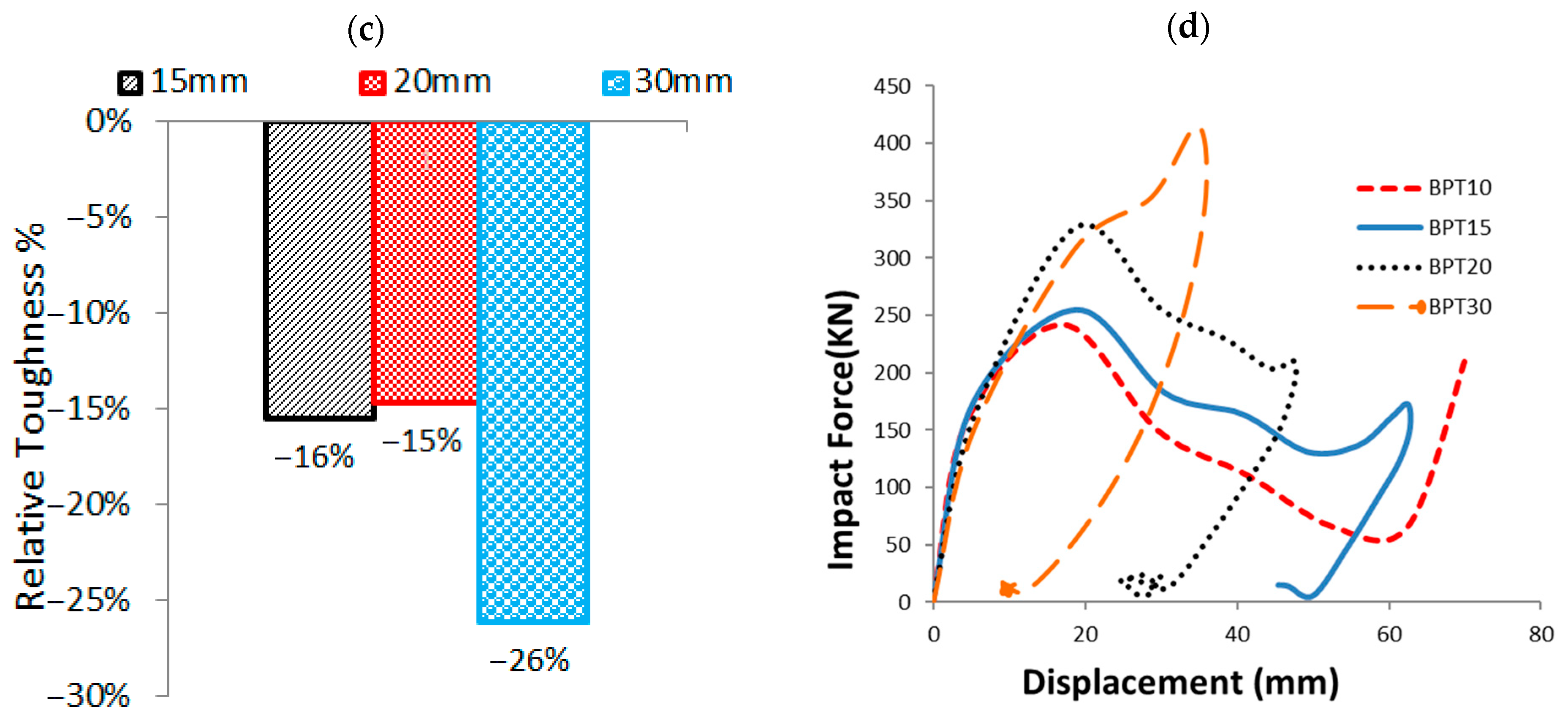
3.4. Base Plate Thickness (T)
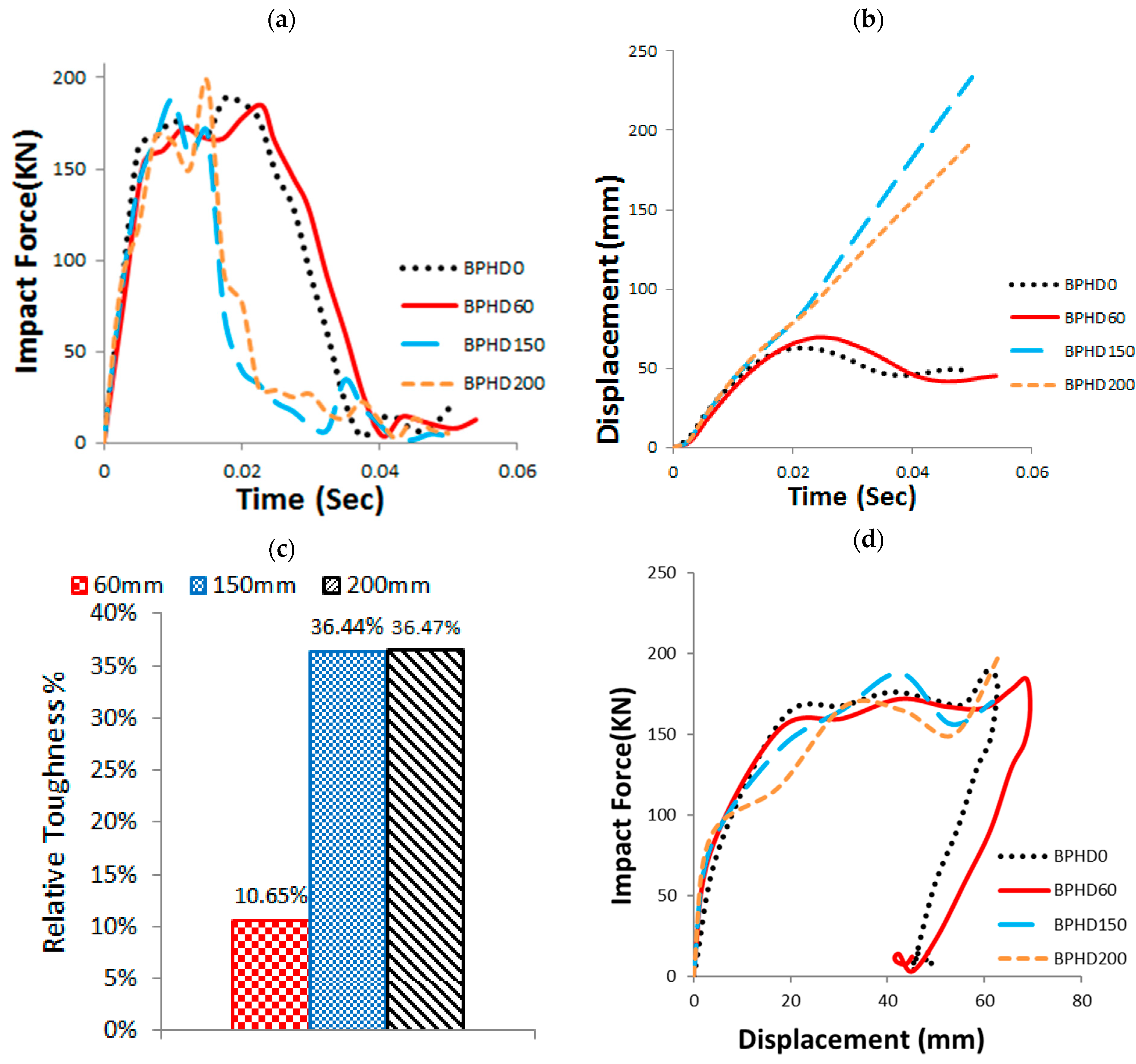
3.5. Electric Cable Hole Diameter (HD)
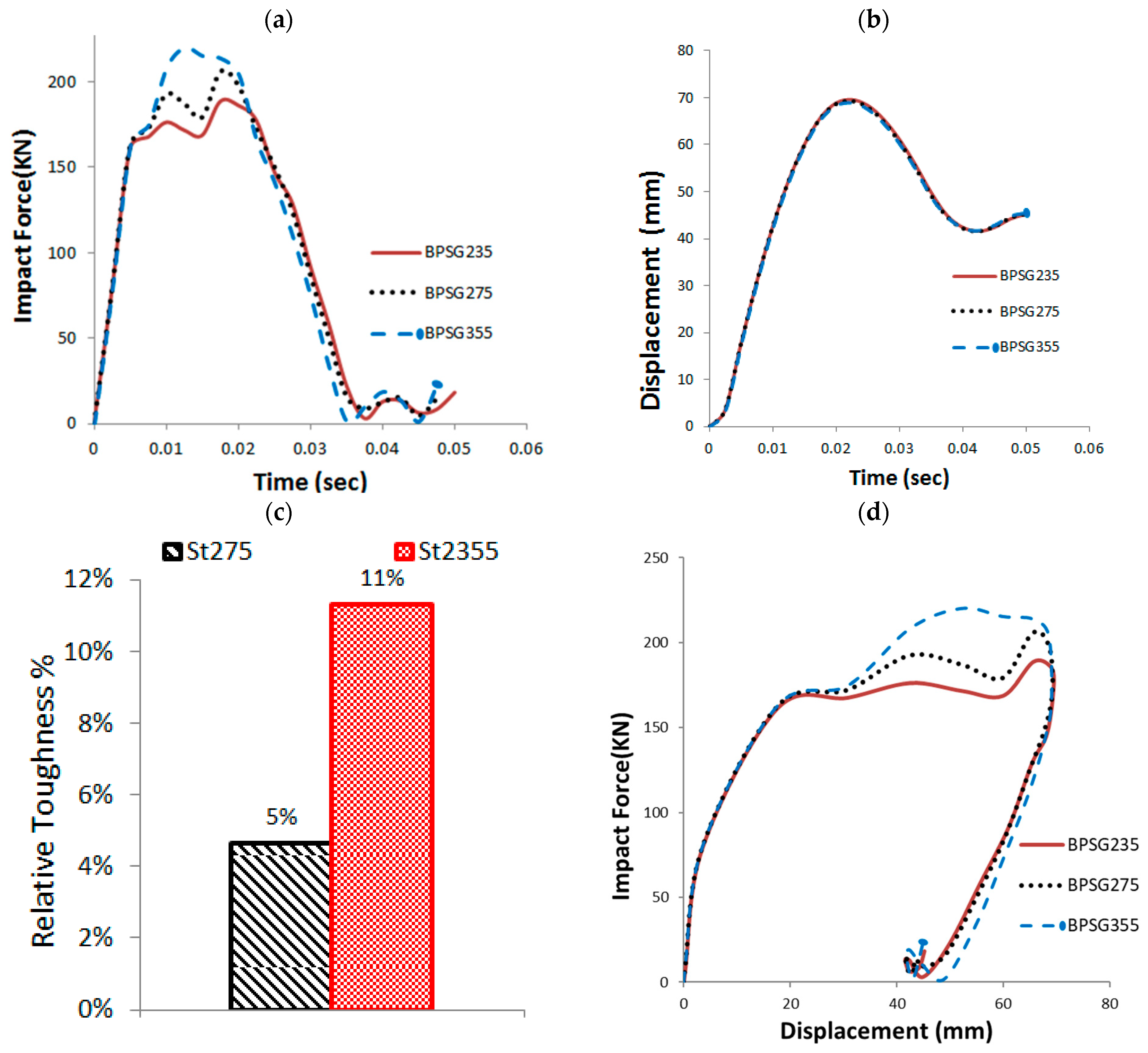
3.6. Base Plate Material Properties (SG)
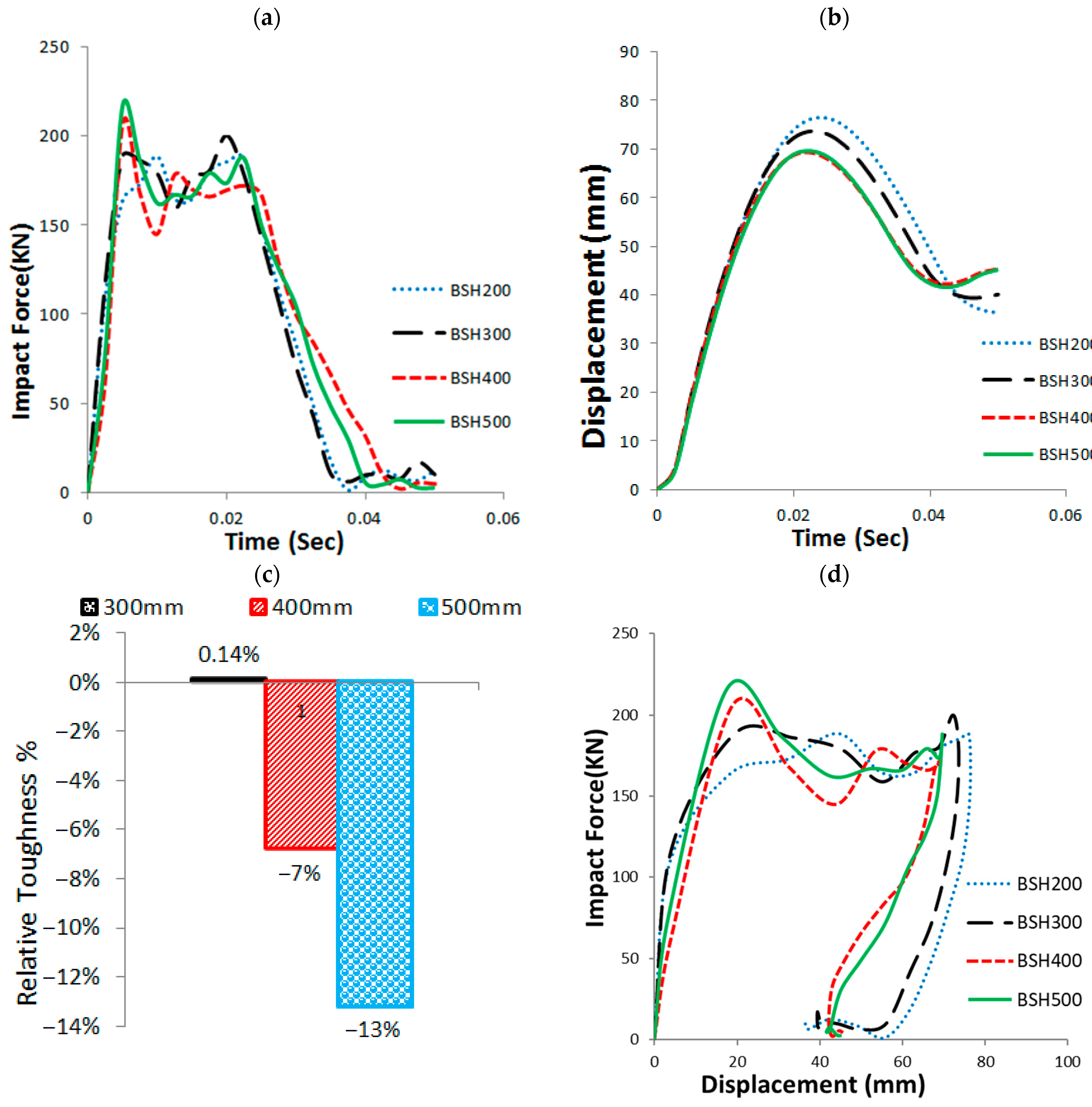
3.7. Base Sleeve Height (BSH)
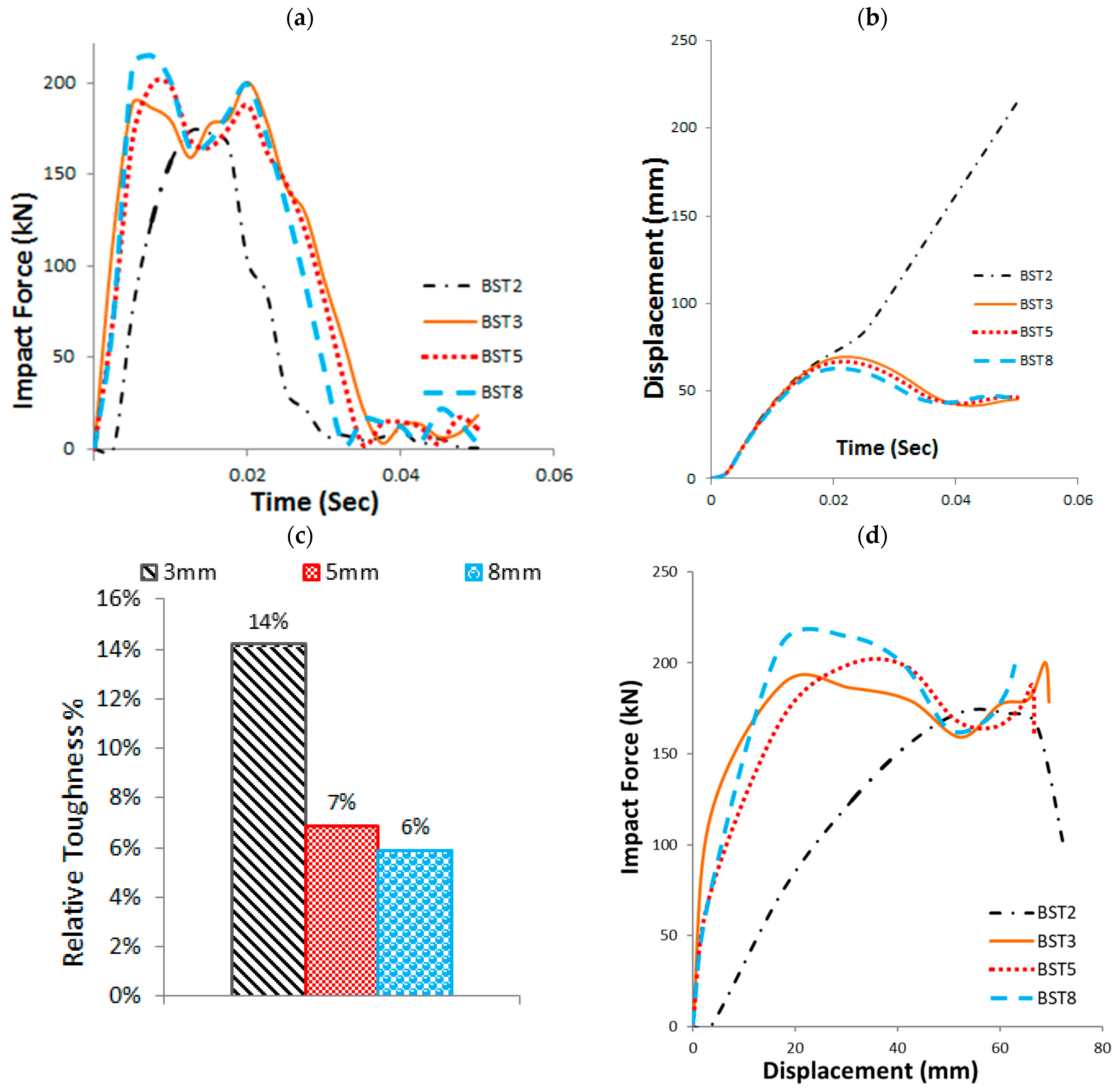
3.8. Base Sleeve Thickness (BST)
3.9. Base Sleeve Material Properties (SG)
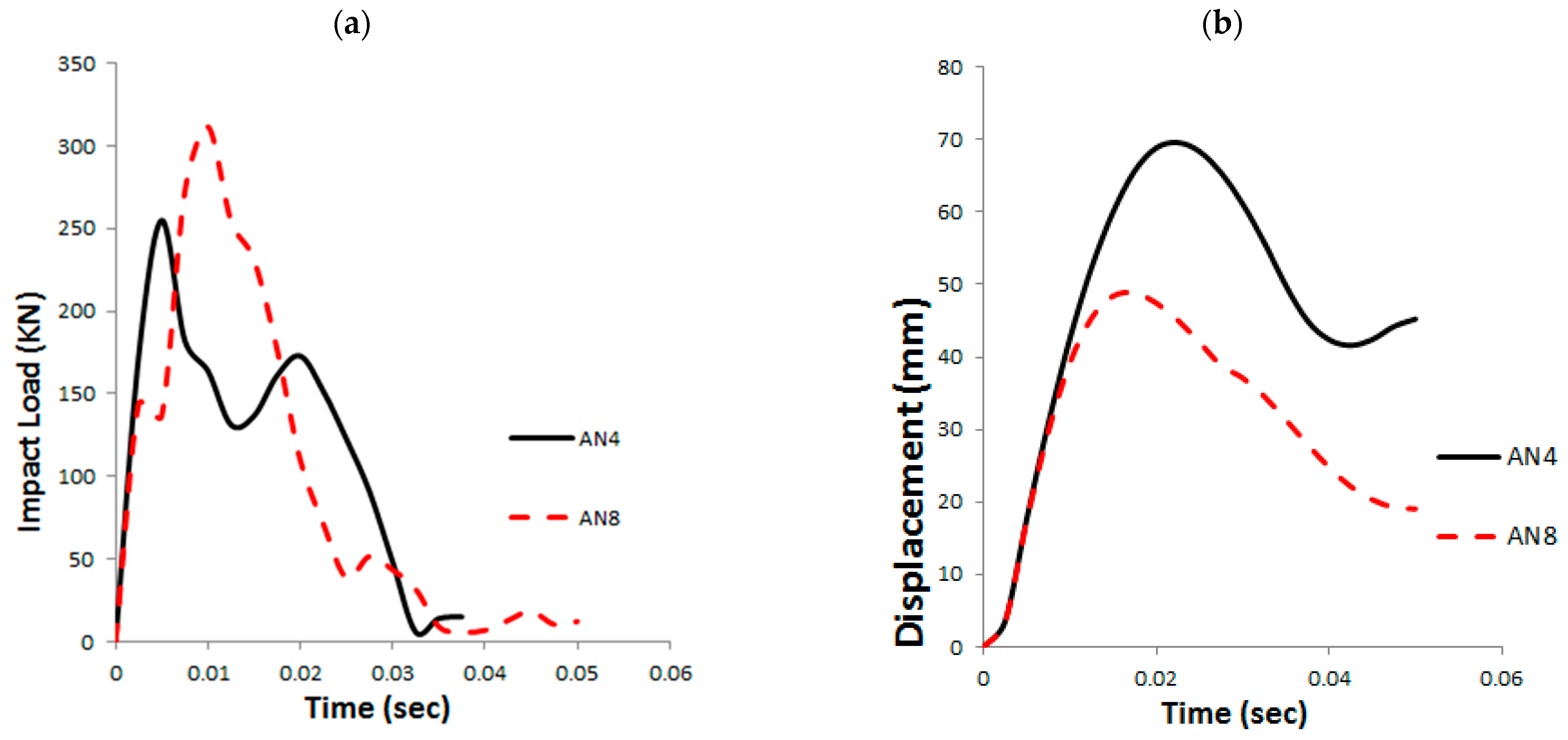
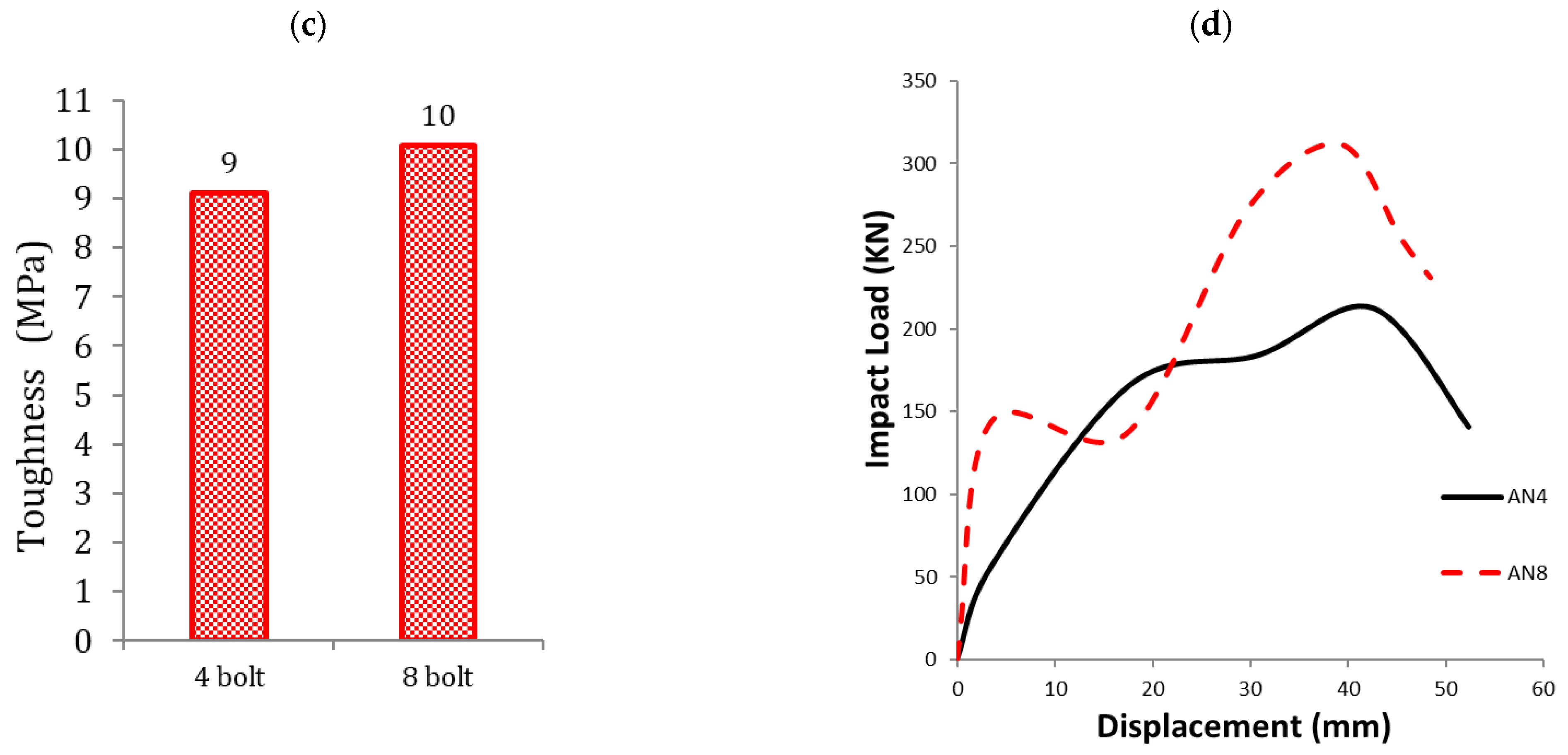
3.10. Anchor Bolts Patterns (AN)
3.11. Anchor Bolts Diameter (AD)
3.12. Anchor Bolts Material Properties (ASG)
3.13. Washer Diameter (WD)
4. Conclusions
- Increasing the GFRP pole wall thickness from 6 mm to 12 mm resulted in a 76% reduction in normalized toughness, indicating a shift to faster collapse with minimal deflection, thereby enhancing passenger safety.
- Increasing the base plate dimensions from 450 mm to 600 mm led to a 35% decrease in normalized toughness and promoted sleeve failure before base plate yielding, facilitating more efficient energy dissipation.
- Increasing the base plate thickness from 10 mm to 30 mm caused a 26% reduction in normalized pole toughness. Thinner plates allowed for more plastic deformation and better energy absorption, while thicker plates led to stiffer behavior and quicker collapse.
- Upgrading the base plate steel grade from S235 to S355 increased normalized toughness by 11%, though this also reduced deformation and shifted failure from the plate to the sleeve-weld region.
- Increasing the base sleeve height from 200 mm to 500 mm led to a 13% reduction in normalized toughness and quicker structural failure. In contrast, increasing the sleeve thickness from 2 mm to 8 mm caused only a 7% reduction in toughness, with thicknesses above 3 mm showing minimal additional benefit.
- Enlarging the electric cable hole diameter from 60 mm to 200 mm increased normalized toughness by up to 36.5%, though it raised local stress concentrations and introduced risks of weld failure.
- Using eight anchor bolts instead of four increased the normalized toughness by 11% and minimized base plate deformation and rotation. However, increasing the anchor bolt diameter from 22 mm to 30 mm reduced normalized toughness by 32%, indicating that larger diameters reduce the pole’s energy absorption capacity.
- Changing the material grade of the base sleeve and anchor bolts from S235 to S355 resulted in minimal changes in normalized toughness—approximately 1.1% and 8% reductions, respectively—demonstrating limited influence on global dynamic performance.
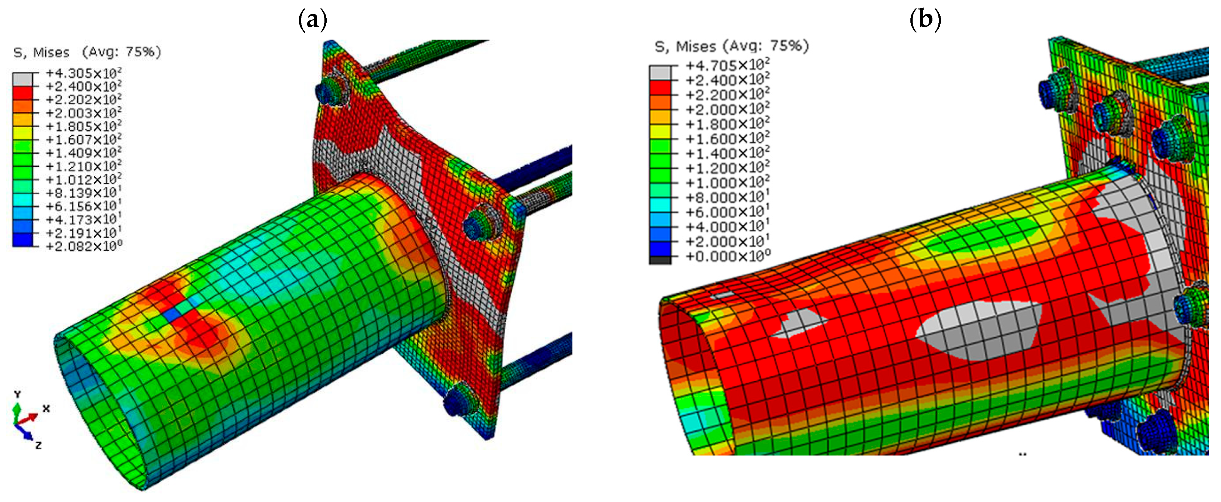
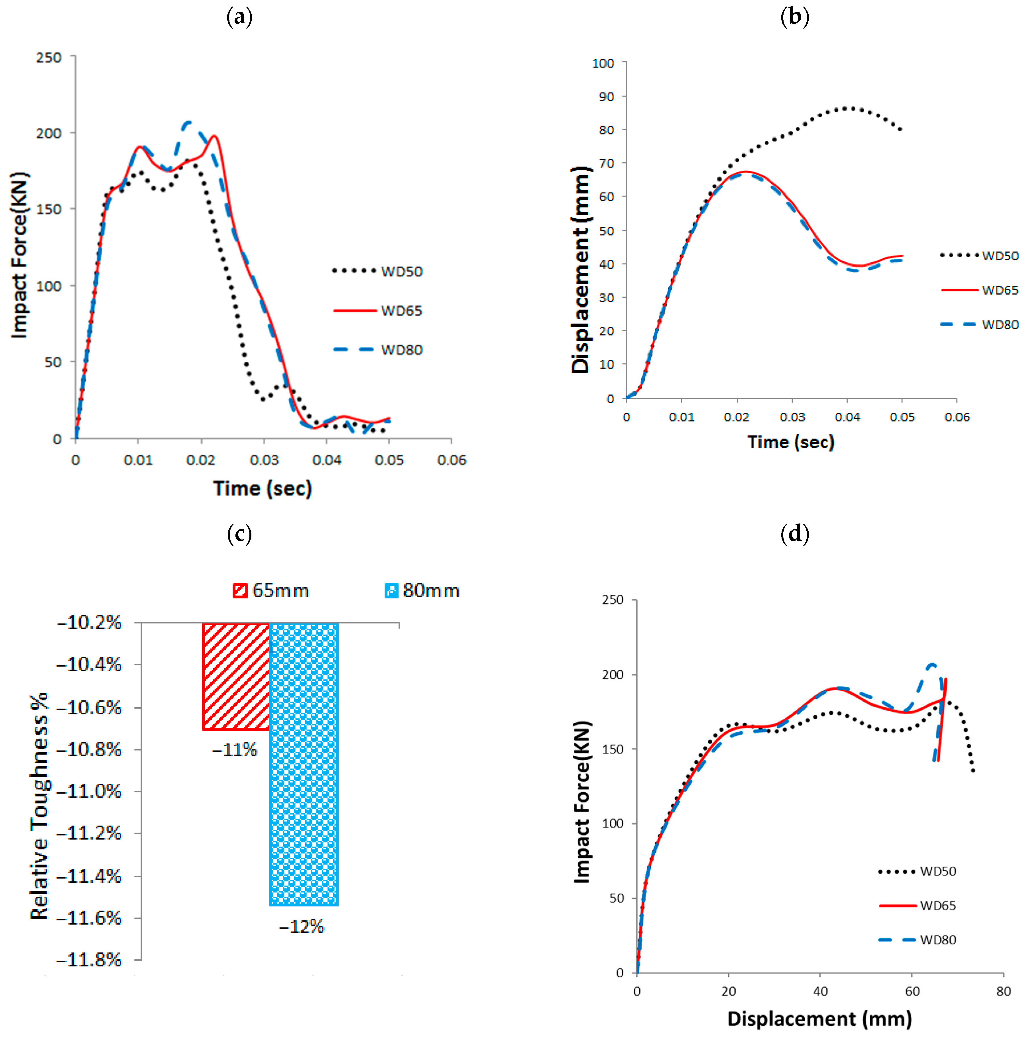
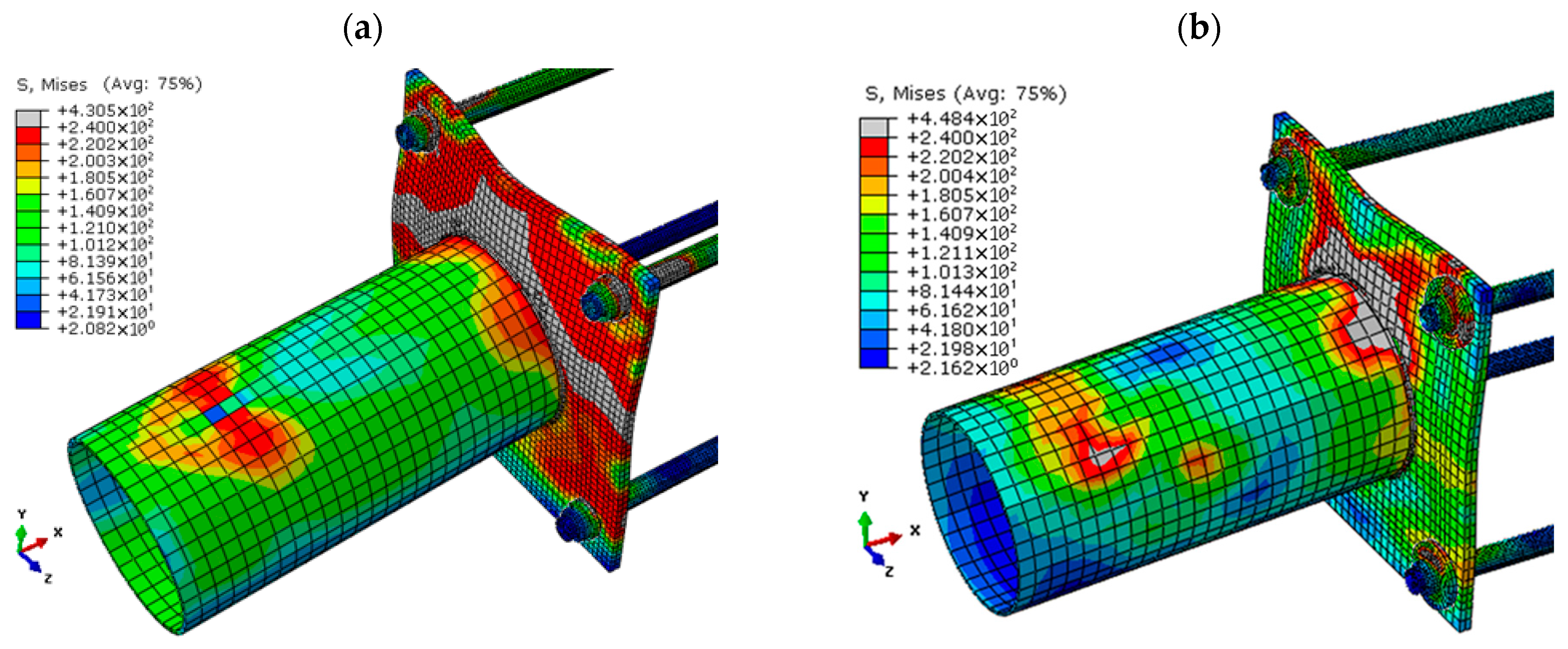
- Increasing the washer diameter from 50 mm to 80 mm led to a 12% reduction in normalized toughness, suggesting a trade-off between improved fixation and reduced energy absorption.
Author Contributions
Funding
Data Availability Statement
Acknowledgments
Conflicts of Interest
References
- Elmarakbi, A.; Fielding, M.N. New Design of Roadside Pole Structure: Crash Analysis of Different Longitudinal Tubes Using LS-DYNA. 2009. Available online: https://www.dynalook.com/conferences/european-conf-2009/B-VI-04.pdf (accessed on 1 April 2024).
- Abdel-Nasser, Y.; Alrajhi, J.; Alardhi, M.; Alkhulaifi, K. Frontal Crash Simulation of Vehicles Against Lighting Columns in Kuwait Using FEM. Int. J. Traffic Transp. Eng. 2013, 2013, 101–105. [Google Scholar] [CrossRef]
- Elmarakbi, A.M.; Sennah, K.M. Frontal impact finite element modeling to develop FRP energy absorbing pole structure. Int. J. Automot. Technol. 2006, 7, 555–564. [Google Scholar]
- Arafa, I.T.; Elhosseiny, O.M.; Nawar, M.T. Damage assessment of perforated steel beams subjected to blast loading. Structures 2022, 40, 646–658. [Google Scholar] [CrossRef]
- Elmarakbi, A.; Krznaric, V.; Sennah, K.; Altenhof, W.; Chapman, M. Crashworthiness of vehicle-to-pole collisions using a hybrid III three-year-old child dummy. Int. J. Veh. Syst. Model. Test. 2013, 8, 1. [Google Scholar] [CrossRef]
- Reddy, T.J.; Rao, Y.V.D.; Narayanamurthy, V. Thin-walled structural configurations for enhanced crashworthiness. Int. J. Crashworth. 2018, 23, 57–73. [Google Scholar] [CrossRef]
- Samtani, N.C.; Kulicki, J.M. Reliability Evaluation of Concrete Cover for Buried Structures from Chloride-Induced Corrosion Perspective. J. Bridge Eng. 2020, 25, 4020049. [Google Scholar] [CrossRef]
- Višnja, A.P.; Lakušić, T. Safety of roadside columns in case of vehicle impact The safety of roadside columns in the event of vehicle impact. Građevinar 2012, 64, 305–313. [Google Scholar]
- Williams, G.L.; Kennedy, J.V.; Carroll, J.A.; Beesley, R. The Use of Passively Safe Signposts and Lighting Columns; TRL: Wokingham, UK, 2008. [Google Scholar]
- EL-Fiky, A.M.; Awad, Y.A.; Elhegazy, H.M.; Hasan, M.G.; Abdel-Latif, I.; Ebid, A.M.; Khalaf, M.A. FRP Poles: A State-of-the-Art-Review of Manufacturing, Testing, and Modeling. Buildings 2022, 12, 1085. [Google Scholar] [CrossRef]
- Stankevich, S.; Bulderberga, O.; Tarasovs, S.; Zeleniakiene, D.; Omastova, M.; Aniskevich, A. Electrical conductivity of glass fiber-reinforced plastic with nanomodified matrix for damage diagnostic. Materials 2021, 14, 4485. [Google Scholar] [CrossRef]
- Tripathi, S.; Gupta, S.; Kumar, V.; Tiwari, P. Hybrid Utility Poles and their application in Power System: Refinement in Construction and Design of Conventional Utility Pole. In Proceedings of the International Conference on Electrical and Electronics Engineering, ICE3 2020, Gorakhpur, India, 14–15 February 2020. [Google Scholar] [CrossRef]
- Metiche, S.; Masmoudi, R. Full-scale flexural testing on fiber-reinforced polymer (FRP) poles. Open Civ. Eng. J. 2007, 1, 37–50. [Google Scholar]
- Metiche, S.; Masmoudi, R. Analysis and design procedures for the flexural behavior of glass fiber-reinforced polymer composite poles. J. Compos. Mater. 2013, 47, 207–229. [Google Scholar] [CrossRef]
- Son, J.K.; Fam, A. Finite element modeling of hollow and concrete-filled fiber composite tubes in flexure: Model development, verification and investigation of tube parameters. Eng. Struct. 2008, 30, 2656–2666. [Google Scholar] [CrossRef]
- Bondok, D.H.; Salim, H.A. Numerical Modeling of Conventional Steel Stud Walls’ Static Resistance for Blast Response Predictions. J. Struct. Eng. 2014, 140. [Google Scholar] [CrossRef]
- Nawar, M.T.; Arafa, I.T.; Elhosseiny, O.M.; El-Zohairy, A. Full static resistance of castellated steel beams with hexagonal web openings for blast response predictions. Eng. Struct. 2021, 245, 112844. [Google Scholar] [CrossRef]
- Desai, N.; Yuan, R. Investigation of bending/buckling characteristics for FRP composite poles. In Proceedings of the Earth and Space 2006—Proceedings of the 10th Biennial International Conference on Engineering, Construction, and Operations in Challenging Environments, League City/Houston, TX, USA, 5–8 March 2006. [Google Scholar] [CrossRef]
- Ibrahim, S.; Polyzois, D. Ovalization analysis of fiber-reinforced plastic poles. Compos. Struct. 1999, 45, 7–12. [Google Scholar] [CrossRef]
- Polyzois, D.; Ibrahim, S.; Raftoyiannis, I.G. Performance of fiber-reinforced plastic tapered poles under lateral loading. J. Compos. Mater. 1999, 33, 941–960. [Google Scholar] [CrossRef]
- Urgessa, G.; Mohamadi, S. Structural Assessment of Fiber-reinforced Polymer Composite Electric Poles. Procedia Eng. 2016, 145, 707–714. [Google Scholar] [CrossRef]
- Fam, A.; Kim, Y.J.; Son, J.K. A numerical investigation into the response of free end tubular composite poles subjected to axial and lateral loads. Thin-Walled Struct. 2010, 48, 650–659. [Google Scholar] [CrossRef]
- Gao, H.; Sun, Y.; Jian, J.; Dong, Y.; Liu, H. Study on mechanical properties and application in communication pole line engineering of glass fiber reinforced polyurethane composites (GFRP). Case Stud. Constr. Mater. 2023, 18, e01942. [Google Scholar] [CrossRef]
- Awad, Y.A.; El-Fiky, A.M.; Elhegazy, H.M.; Hasan, M.G.; Yousef, I.A.; Ebid, A.M.; Khalaf, M.A. Behavior of Centrifuged GFRP Poles Under Lateral Deflection. Civ. Eng. J. 2023, 9, 1389–1401. [Google Scholar] [CrossRef]
- Nawar, M.T.; Kaka, M.E.; El-Zohairy, A.; Elhosseiny, O.; Arafa, I.T. Effect of Supporting Base System on the Flexural Behavior and Toughness of the Lighting GFRP Poles. Sustainability 2022, 14, 12614. [Google Scholar] [CrossRef]
- Noh, J.; Ghadimi, B.; Russo, S.; Rosano, M. Assessment of FRP pultruded elements under static and dynamic loads. Compos. Struct. 2018, 202, 17–28. [Google Scholar] [CrossRef]
- Polyzois, D.; Raftoyiannis, I.G.; Philopulos, D. An experimental survey of the static and dynamic behavior of jointed composite GFRP tapered poles. Mech. Adv. Mater. Struct. 2007, 14, 203–212. [Google Scholar] [CrossRef]
- Caracoglia, L.; Velazquez, A. Experimental comparison of the dynamic performance for steel, aluminum and glass-fiber-reinforced-polymer light poles. Eng. Struct. 2008, 30, 1113–1123. [Google Scholar] [CrossRef]
- Zhang, Y.; Pan, R.; Xiao, F. Numerical research on impact performance of bridge columns with aluminum foam protection devices. Int. J. Distrib. Sens. Netw. 2020, 16, 1550147720974538. [Google Scholar] [CrossRef]
- Al-Thairy, H.; Wang, Y.C. Simplified FE vehicle model for assessing the vulnerability of axially compressed steel columns against vehicle frontal impact. J. Constr. Steel Res. 2014, 102, 190–203. [Google Scholar] [CrossRef]
- Kang, H.; Kim, J. Response of a steel column-footing connection subjected to vehicle impact. Struct. Eng. Mech. 2017, 63, 125–136. [Google Scholar] [CrossRef]
- Wang, J.; GangaRao, H.; Liang, R.; Liu, W. Experimental and Analytical Responses of Hollow and Concrete-Filled GFRP Tube Columns under Impact. J. Compos. Constr. 2017, 21, 04017013. [Google Scholar] [CrossRef]


| Properties | E-Glass | # 90 Isophthalic Polyester Resin | Equivalent GFRP |
|---|---|---|---|
| Density (gm/cm3) | 2.54 | 1.08 | 1.85 |
| Poisson’s ratio (v) | 0.2 | 0.3 | 0.25 |
| Tensile modulus (GPa) | 72 | 3.4 | 18 |
| Shear modulus (Gpa) | 30 | 1.37 | 4.8 |
| Tensile strength (Mpa) | 1500 | 79 | 370 |
| Flexural strength (Mpa) | -- | -- | 365 |
| Percent of glass fiber by weight | -- | -- | 45% |
| Material | Base Sleeve, Base Plate | Anchor Bolt |
|---|---|---|
| Density (gm/cm3) | 7.8 | 7.8 |
| Poisson’s ratio (v) | 0.26 | 0.26 |
| Tensile modulus (Gpa) | 207 | 207 |
| Shear Modulus (Gpa) | 80 | 80 |
| Tensile Strength (Mpa) | 360 | 520 |
| Yield Strength (Mpa) | 240 | 360 |
| Case Study | FE Pole | GFRP Pole Dimensions | Base Sleeve Dimensions | Base Plate Dimensions | Anchor bolts | Peak Impact Force (KN) | |||||||||||||
|---|---|---|---|---|---|---|---|---|---|---|---|---|---|---|---|---|---|---|---|
| Label | PBD | PTD | PT | BSSG | BSBD | BSTD | BST | BSH | BPSG | BPHD | BPT | BPL | ASG | WD | AD | AL | AN | ||
| (mm) | (mm) | (mm) | (mm) | (mm) | (mm) | (mm) | (mm) | (mm) | (mm) | (mm) | (mm) | (mm) | |||||||
| GFRP Pole Thickness | PT6 | 256 | 229 | 6 | S235 | 246 | 240 | 3 | 300 | S235 | 0 | 30 | 450 | S235 | 50 | 22 | 800 | 4 | 215 |
| PT8 | 256 | 229 | 8 | S235 | 246 | 240 | 3 | 300 | S235 | 0 | 30 | 450 | S235 | 50 | 22 | 800 | 4 | 225 | |
| PT10 | 256 | 229 | 10 | S235 | 246 | 240 | 3 | 300 | S235 | 0 | 30 | 450 | S235 | 50 | 22 | 800 | 4 | 238 | |
| PT12 | 256 | 229 | 12 | S235 | 246 | 240 | 3 | 300 | S235 | 0 | 30 | 450 | S235 | 50 | 22 | 800 | 4 | 252 | |
| GFRP Pole Bottom Diameter | PBD184 | 184 | 157 | 8 | S235 | 174 | 169 | 3 | 300 | S235 | 0 | 30 | 450 | S235 | 50 | 22 | 800 | 4 | 172 |
| PBD256 | 256 | 229 | 8 | S235 | 246 | 277 | 3 | 300 | S235 | 0 | 30 | 450 | S235 | 50 | 22 | 800 | 4 | 223 | |
| PBD328 | 328 | 301 | 8 | S235 | 318 | 313 | 3 | 300 | S235 | 0 | 30 | 450 | S235 | 50 | 22 | 800 | 4 | 246 | |
| Base Plate Dimensions L, B | BPL450 | 256 | 229 | 8 | S235 | 246 | 237 | 3 | 500 | S235 | 0 | 15 | 450 | S235 | 50 | 22 | 800 | 4 | 178 |
| BPL500 | 256 | 229 | 8 | S235 | 246 | 237 | 3 | 500 | S235 | 0 | 15 | 500 | S235 | 50 | 22 | 800 | 4 | 189 | |
| BPL550 | 256 | 229 | 8 | S235 | 246 | 237 | 3 | 500 | S235 | 0 | 15 | 550 | S235 | 50 | 22 | 800 | 4 | 198 | |
| BPL600 | 256 | 229 | 8 | S235 | 246 | 237 | 3 | 500 | S235 | 0 | 15 | 600 | S235 | 50 | 22 | 800 | 4 | 248 | |
| Base Plate Thickness T | BPT10 | 256 | 229 | 8 | S235 | 246 | 237 | 3 | 500 | S235 | 0 | 10 | 450 | S235 | 50 | 22 | 800 | 4 | 242 |
| BPT15 | 256 | 229 | 8 | S235 | 246 | 237 | 3 | 500 | S235 | 0 | 15 | 450 | S235 | 50 | 22 | 800 | 4 | 255 | |
| BPT20 | 256 | 229 | 8 | S235 | 246 | 237 | 3 | 500 | S235 | 0 | 20 | 450 | S235 | 50 | 22 | 800 | 4 | 327 | |
| BPT30 | 256 | 229 | 8 | S235 | 246 | 237 | 3 | 500 | S235 | 0 | 30 | 450 | S235 | 50 | 22 | 800 | 4 | 415 | |
| Base Plate Cable Hole Diameter | BPHD0 | 256 | 229 | 8 | S235 | 246 | 237 | 3 | 500 | S235 | 0 | 15 | 450 | S235 | 50 | 22 | 800 | 4 | 189 |
| BPHD60 | 256 | 229 | 8 | S235 | 246 | 237 | 3 | 500 | S235 | 60 | 15 | 450 | S235 | 50 | 22 | 800 | 4 | 185 | |
| BPHD150 | 256 | 229 | 8 | S235 | 246 | 237 | 3 | 500 | S235 | 150 | 15 | 450 | S235 | 50 | 22 | 800 | 4 | 171 | |
| BPHD200 | 256 | 229 | 8 | S235 | 246 | 237 | 3 | 500 | S235 | 200 | 15 | 450 | S235 | 50 | 22 | 800 | 4 | 167 | |
| Base Plate Steel Grade | BPSG235 | 256 | 229 | 8 | S235 | 246 | 237 | 3 | 500 | S235 | 0 | 15 | 450 | S235 | 50 | 22 | 800 | 4 | 189 |
| BPSG275 | 256 | 229 | 8 | S235 | 246 | 237 | 3 | 500 | S275 | 0 | 15 | 450 | S235 | 50 | 22 | 800 | 4 | 206 | |
| BPSG355 | 256 | 229 | 8 | S235 | 246 | 237 | 3 | 500 | S355 | 0 | 15 | 450 | S235 | 50 | 22 | 800 | 4 | 220 | |
| Base Sleeve Height | BSH200 | 256 | 229 | 8 | S235 | 246 | 241 | 3 | 200 | S235 | 0 | 15 | 450 | S235 | 50 | 22 | 800 | 4 | 197 |
| BSH300 | 256 | 229 | 8 | S235 | 246 | 241 | 3 | 300 | S235 | 0 | 15 | 450 | S235 | 50 | 22 | 800 | 4 | 216 | |
| BSH400 | 256 | 229 | 8 | S235 | 246 | 233 | 3 | 400 | S235 | 0 | 15 | 450 | S235 | 50 | 22 | 800 | 4 | 227 | |
| BSH500 | 256 | 229 | 8 | S235 | 246 | 237 | 3 | 500 | S235 | 0 | 15 | 450 | S235 | 50 | 22 | 800 | 4 | 233 | |
| Base Sleeve Thickness | BST2 | 256 | 229 | 8 | S235 | 246 | 237 | 2 | 500 | S235 | 0 | 15 | 450 | S235 | 50 | 22 | 800 | 4 | 173 |
| BST3 | 256 | 229 | 8 | S235 | 246 | 237 | 3 | 500 | S235 | 0 | 15 | 450 | S235 | 50 | 22 | 800 | 4 | 189 | |
| BST5 | 256 | 229 | 8 | S235 | 246 | 237 | 5 | 500 | S235 | 0 | 15 | 450 | S235 | 50 | 22 | 800 | 4 | 199 | |
| BST8 | 256 | 229 | 8 | S235 | 246 | 237 | 8 | 500 | S235 | 0 | 15 | 450 | S235 | 50 | 22 | 800 | 4 | 215 | |
| Base Sleeve Material | BSSG235 | 256 | 229 | 8 | S235 | 246 | 237 | 3 | 500 | S235 | 0 | 15 | 450 | S235 | 50 | 22 | 800 | 4 | 189 |
| BSSG275 | 256 | 229 | 8 | S275 | 246 | 237 | 3 | 500 | S235 | 0 | 15 | 450 | S235 | 50 | 22 | 800 | 4 | 194 | |
| BSSG355 | 256 | 229 | 8 | S355 | 246 | 237 | 3 | 500 | S235 | 0 | 15 | 450 | S235 | 50 | 22 | 800 | 4 | 196 | |
| Anchor Number | AN4 | 256 | 229 | 8 | S235 | 246 | 237 | 3 | 500 | S235 | 0 | 30 | 450 | S235 | 50 | 22 | 800 | 4 | 213 |
| AN8 | 256 | 229 | 8 | S235 | 246 | 237 | 3 | 500 | S235 | 0 | 30 | 450 | S235 | 50 | 22 | 800 | 8 | 312 | |
| Anchor Diameter | AD22 | 256 | 229 | 8 | S235 | 246 | 237 | 3 | 500 | S235 | 0 | 30 | 450 | S235 | 50 | 22 | 800 | 4 | 173 |
| AD26 | 256 | 229 | 8 | S235 | 246 | 237 | 3 | 500 | S235 | 0 | 30 | 450 | S235 | 50 | 26 | 800 | 4 | 178 | |
| AD30 | 256 | 229 | 8 | S235 | 246 | 237 | 3 | 500 | S235 | 0 | 30 | 450 | S235 | 50 | 30 | 800 | 4 | 181 | |
| Anchor Material | ASG235 | 256 | 229 | 8 | S235 | 246 | 237 | 3 | 500 | S235 | 0 | 30 | 450 | S235 | 50 | 22 | 800 | 4 | 173 |
| ASG275 | 256 | 229 | 8 | S235 | 246 | 237 | 3 | 500 | S235 | 0 | 30 | 450 | S275 | 50 | 22 | 800 | 4 | 178 | |
| ASG355 | 256 | 229 | 8 | S235 | 246 | 237 | 3 | 500 | S235 | 0 | 30 | 450 | S355 | 50 | 22 | 800 | 4 | 189 | |
| Washer Diameter | WD30 | 256 | 229 | 8 | S235 | 246 | 237 | 3 | 500 | S235 | 0 | 30 | 450 | S235 | 50 | 22 | 800 | 4 | 181 |
| WD40 | 256 | 229 | 8 | S235 | 246 | 237 | 3 | 500 | S235 | 0 | 30 | 450 | S236 | 65 | 22 | 800 | 4 | 196 | |
| WD80 | 256 | 229 | 8 | S235 | 246 | 237 | 3 | 500 | S235 | 0 | 30 | 450 | S237 | 80 | 22 | 800 | 4 | 206 | |
Disclaimer/Publisher’s Note: The statements, opinions and data contained in all publications are solely those of the individual author(s) and contributor(s) and not of MDPI and/or the editor(s). MDPI and/or the editor(s) disclaim responsibility for any injury to people or property resulting from any ideas, methods, instructions or products referred to in the content. |
© 2025 by the authors. Licensee MDPI, Basel, Switzerland. This article is an open access article distributed under the terms and conditions of the Creative Commons Attribution (CC BY) license (https://creativecommons.org/licenses/by/4.0/).
Share and Cite
Nawar, M.T.; Elbelbisi, A.; Kaka, M.E.; Elhosseiny, O.; Arafa, I.T. Dynamic Behavior of Lighting GFRP Pole Under Impact Loading. Buildings 2025, 15, 2341. https://doi.org/10.3390/buildings15132341
Nawar MT, Elbelbisi A, Kaka ME, Elhosseiny O, Arafa IT. Dynamic Behavior of Lighting GFRP Pole Under Impact Loading. Buildings. 2025; 15(13):2341. https://doi.org/10.3390/buildings15132341
Chicago/Turabian StyleNawar, Mahmoud T., Ahmed Elbelbisi, Mostafa E. Kaka, Osama Elhosseiny, and Ibrahim T. Arafa. 2025. "Dynamic Behavior of Lighting GFRP Pole Under Impact Loading" Buildings 15, no. 13: 2341. https://doi.org/10.3390/buildings15132341
APA StyleNawar, M. T., Elbelbisi, A., Kaka, M. E., Elhosseiny, O., & Arafa, I. T. (2025). Dynamic Behavior of Lighting GFRP Pole Under Impact Loading. Buildings, 15(13), 2341. https://doi.org/10.3390/buildings15132341