Article

On-Site Safety Inspections Through Marker-Less Augmented Reality and Blockchain Notarization of BIM-Based Processes †

Department of Construction, Civil Engineering and Architecture, Polytechnic University of Marche, 60131 Ancona, Italy
*
Author to whom correspondence should be addressed.
This paper is an extended version of our paper published in Augmented Reality, seamless indoor and outdoor localization and Blockchain for safety inspection support in construction sites. In Proceedings of the 24th International Conference on Construction Applications of Virtual Reality (CONVR 2024), Sydney, Australia, 4–6 November 2024.
Buildings 2025, 15(13), 2318; https://doi.org/10.3390/buildings15132318
Submission received: 27 March 2025 / Revised: 10 June 2025 / Accepted: 17 June 2025 / Published: 2 July 2025

Abstract

The digitization that is impacting the construction sector still encounters areas where it is hindered. Safety is one of them—in Italy, even health and safety plans have to be digitally modeled. In this article, a methodology is presented for the digitization of health and safety plans and their visualization on-site using augmented reality and a seamless system for indoor–outdoor localization. Safety requirements for equipment are modeled as customized property within BIM models. Then, the interoperable-format IFC is used to upload the model in a BIM platform. On-site outdoor localization is ensured by a GPS-RTK system, while for indoor spaces, an artificial intelligence algorithm that recognizes features is used. In this research, an application that supports a seamless outdoor–indoor transition is proposed, with the display of inspection information through augmented reality and a blockchain notarization of images taken on-site and aligned with BIM models. The results of indoor and outdoor alignment are presented below. The experiment regarding augmented reality information display and the photo notarization procedure are also reported. This methodology improves the site inspection process by supporting the traceability of operations.

1. Introduction

1.1. Background

Ensuring safety on construction sites is a persistent challenge, as the AECO sector is constantly evolving, with complex processes and emerging methodologies [1]. The construction industry is also one of the most dangerous industries when examining the number of work-related accidents, injuries, and fatalities. Among the various causes of the high incidence of fatal accidents in construction is the scarcity of inspections that can certify compliance with safety requirements and Health and Safety (H&S) plans [2].
Among other things, safety inspections present some challenges:
  • Contractors are not incentivized to promote regular inspections [3];
  • The identification of risks and non-conformities is also linked to the inspector’s experience [4];
  • Inspection procedures are still conducted with traditional paper-based methods with the risk of loss of information [5].
To address these challenges, the introduction of digital methods and tools for process management can be decisive. First, it could help inspectors conduct assessments correctly, providing real-time, on-site guidance on what needs to be verified. Second, it could offer a reliable method to certify the completion of inspections and mitigate fraud in the reporting of inspection results [6]. In light of these objectives, the integration of new technologies for data collection and analysis has the potential to introduce disruptive innovation in construction site safety management.
Despite the increasing adoption of digital tools in various aspects of the construction industry, safety remains one of the least impacted areas in terms of digitization. There is significant room for improvement in H&S practices and a pressing need to accelerate progress in safety measures within construction companies to safeguard workers from potential injuries [7].
In addition, there is the digital twin paradigm that has recently been present in the construction industry and represents huge potential for growth in safety risk management [8]. Compared with DT in non-construction sectors, it is evident that this approach has unique characteristics in the construction industry, namely the association with BIM and the emphasis on the geometric reconstruction of building entities [9]. One of the features of digital twins that makes them particularly suitable for safety management is real-time monitoring. Indeed, the early and accurate detection of events such as near-misses is critical. While traditional inspector-based methods are slow, require a lot of personnel, and fail to effectively monitor three-dimensional events, digital twin technology represents a promising solution, combining real-time monitoring, simulation, and interaction in 3D virtual environments, as in the case developed by [10]. And it is precisely through the ability to take 3D space into account, including by integrating BIM models of the site, that some machinery simulations (such as cranes) enable better management of risk situations. The crane digital twin framework presented by [11] supports planning in the early stages, lowers operational risks, and promotes safer and more cost-effective construction practices, resulting in a scalable solution that can be adapted to different construction scenarios.
This article presents a novel prior system for managing safety inspections on construction sites through digital technology. The first aspect addressed is the challenge of modeling safety prescriptions. Currently, Building Information Modeling (BIM) lacks dedicated standards for safety-related data representation, necessitating the identification of new methods for encoding safety information relevant to inspections. Another critical issue concerns the communication of this information directly on-site and establishing a secure method for notarizing inspection outcomes.
The proposed preliminary system introduces a comprehensive solution that integrates several cutting-edge technologies. It includes security information modeling and dissemination through a BIM platform (WeBIM), on-site visualization through Augmented Reality (AR), and the integration of GPS-RTK-derived positioning data for outdoor environments, as well as alignment algorithms for indoor positioning. In addition, the system enables the automatic collection of inspection photos aligned to the BIM model and securely authenticated using blockchain technology, guaranteeing authenticity and preventing data manipulation.
The research questions addressed in this study are as follows:
RQ1: Can safety prescription be represented efficiently in BIM models?
RQ2: Can augmented reality be the right technology for the representation of information on-site?
RQ3: Is the proposed procedure a feasible way to conduct inspections?
The approach presented in this paper embodies the Digital Twin (DT) concept, facilitating a seamless flow of information between the WeBIM platform and the construction site. Information is first transmitted from WeBIM to the site, enabling real-time guidance for inspections, and then inspection data, including photographic evidence, is retrieved from the site. This allows remote operators to check inspection results in real time, improving supervision and accountability.
Leveraging these advances, the proposed system provides a robust framework for improving safety inspections in the construction industry, ultimately fostering a safer working environment and driving the digital transformation of health and safety practices on construction sites.

1.2. State of the Art

1.2.1. Digital H&S Plan

Digital approaches and innovative technologies in the construction sector are still underutilized and remain a niche topic [12]. This is even more evident when it comes to safety, one of the most underestimated aspects, the correct implementation of which is almost entirely overlooked during the design phase. This area of construction is characterized by a high level of complexity, as it is closely linked to the project execution phase and, consequently, to all site- and operation-related complications. Moreover, safety management is influenced by the human factor, which is inherently unpredictable [13].
All of this, combined with the lack of standardization on the subject, makes it even more challenging to address safety through digitalization, which is approached with a weak and limited application of the BIM methodology to safety-related topics [1]. In this context, and in contrast to the lack of governmental mandates in other countries [12], Italy has been promoting the introduction of digital methods and tools for construction management in recent years, even at the regulatory level.
Specifically regarding safety, Legislative Decree 36/2023—the Italian law regulating public procurement, including construction—states that information models (BIM) must integrate details related to the health and safety plan. Additionally, Italian regulations require the delivery of a construction site representation in all its phases, indicating work areas, storage spaces, internal roads, and the arrangement of equipment and safety measures.
Since visualization is recognized as the most promising feature of BIM [14], and considering that from the beginning of 2025, information models will have contractual validity in Italy, the unification of representation methods can only optimize workflow processes. However, BIM primarily focuses on representing building components, mostly omitting crucial aspects such as processes, economics, and timelines. Even though the standard is periodically updated to include missing domains (e.g., IfcBridge, IfcRoad), a process-centered vision is still lacking, as well as safety-related aspects.
At the same time, many researchers have explored the idea of developing an ontology for construction site safety, but none of these efforts have yet gained widespread adoption or practical application.
As a result, integrating BIM (within the IFC schema) into construction processes requires extensive data connection and integration. Safety is no exception—since it is not covered by the IFC standard, modeling safety measures, designing site layouts, and embedding relevant on-site information remains a challenge. This is why the implementation of BIM safety management is still insufficient, and the risk of disruption with current procedures is high.
BIM-based modeling can also enhance safety understanding and communication, especially when applied during the design and construction planning phases [15], and may also provide support for inspections [16,17].
Regarding construction site safety monitoring, processes still heavily rely on manual observation, which is time-consuming and prone to errors.
In many cases, BIM models are primarily used to represent geometry, while rule verification is carried out using external software specifically designed for compliance checks [7,18]. However, this approach limits verification to proprietary software, preventing the full utilization of the open IFC format. Furthermore, if this information is needed for on-site inspections, its confinement within specialized software makes it difficult to transfer or stream. Potentially unsafe areas and safety requirements can be defined automatically or manually within a BIM model [19].
In [17], an alternative approach is proposed, where inspection-related data is directly embedded into the IFC format. This method offers several advantages: first, the construction safety manager can enter information without needing to learn new tools; second, the open format seamlessly combines geometric and informational data. This enables the use of this representation for direct on-site applications to support inspections, particularly for less experienced inspectors [7]. Finally, studies have shown that the technologies are even more effective with integrated use, like in the case of BIM and sensors or AR [12].

1.2.2. The Benefits Provided by AR/MR for On-Site Applications

Several levels of applications of Mixed Reality and Augmented Reality (AR/MR) in the construction industry have been worked out and showcased in the last decade. They mainly rely on the use of holograms superimposed over the real-world view, either to add information layers that can show aspects not detectable by human operators or to enrich knowledge as a result of analyses of available information. Representative prototypes have included a method for electrical system component visualization on-site using an MR headset [11] and even a visualization tool to locate MEP components right before, and in support of, their installation on-site [12]. Another type of application enables showing retrofit design projects or building components along with their specifications in an immersive way while walking across the building, hence facilitating understanding [13,14]. A popular topic is training personnel through advanced visualization technologies. Although the majority of these applications make use of virtual reality executed off-site, by transporting operators in a totally different virtual world [15], e.g., training operators in the use of cutting equipment on-site [2], AR/MR is the only technology that can allow trainees to experience real construction site conditions, such as working at heights in a varied range of settings [16]. An excavator augmented reality mobile app was prototyped to navigate a 360° tracked piece of equipment in different work environments. The main purpose of this study was increasing safety standards in excavation and earthmoving processes on construction sites [17].
Among the opportunities for improvement, the necessity of improving emergency and safety reached the highest agreement. Any customization of AR/MR represents a great challenge because making content usable on-site requires finding quick and effective methods of communication, which involves sending data and visualizing them on construction sites.
Furthermore, spatial registration has always been considered one of the most challenging aspects of an AR/MR system and is needed to provide a smooth immersive experience. Technically, spatial registration is responsible for computing a user’s location and orientation in accordance with real-world coordinate systems [18]. Spatial registration can be implemented either as a “marker-based” approach, which is simpler in the setup phase, or a “marker-less” approach. The first one involves markers, such as 2D symbols and pictures, 3D objects in the real environment [19], and even infrared signals and RFID tags [20]. As far as marker-less approaches are concerned, the relative position between any virtual objects and the real environment is computed through localization technologies. One the most widespread localization technology is the Global Navigation Satellite System (GNSS) because of its reliability and availability in large outdoor areas. In addition, GNSS receivers have already been integrated in every mobile device, which facilitates their adoption [19].
However, indoor and outdoor scenarios must be confronted in different ways. In the case of indoor registration, the use of markers should be avoided because it would require their previous installation in a facility, and this could generate aesthetic issues. Natural markers are not always available in a facility [21]. Among the several marker-less approaches that have been developed and tested, it was found that Wi-Fi fingerprinting technology often loses accuracy when multiple mobile devices are involved [22]. In contrast, an approach called image-based localization gave good results. Within this approach, location is tackled by estimating a camera pose from the correspondences established between sparse local features and a 3D Structure-from-Motion (SfM) map of the scene [23]. It usually is implemented thanks to image retrieval methodologies, which allow this pipeline to scale to large scenes, too [24]. At every iteration, this approach attempts to match the closest image to the queried image among a preliminarily prepared dataset. The dataset can be either made of photographs or rendered from three-dimensional structure estimation. Recent approaches that applied this end-to-end pipeline with neural networks were successful [25,26] and showed great potential in developing indoor AR registration applications for non-expert users, too [21]. In the case of outdoor registration, approaches enabling the placement of virtual objects relative to a local reference frame with the use of SLAM-based techniques have limited reliability due to several reasons. The first is due to the expanded spatial dimensions, and the second is due to the absence of readily available reference points. Also, the high computational costs in large environments is a challenge; finally, the dynamic nature of external spaces undergoing frequent changes hampers reliability. Due to these reasons, the AR registration approach outdoors must rely on an absolute reference system [27,28], which suggests the application of hybrid AR registration approaches. Good performance was achieved by the combined use of IMU and high-precision GNSS, such as in the case of Real-Time Kinematics (RTK). This method has successfully been tested to display underground pipelines and subsurface data [29,30], to perform urban navigation [31,32], to support agricultural vehicle navigation [33], and even for the alignment of multiple smaller maps from an existing SLAM tracking system [28]. Evidence shows that single components of RTK receivers are becoming more and more affordable in recent years; hence, it can be assumed that this will facilitate the proliferation of this technology and its applications [29].

1.2.3. Blockchain

Distributed Ledger Technologies (DLTs) and blockchains offer a decentralized and secure approach to tracing and controlling processes along their execution. DLTs are based on large networks of computing nodes that implement a distributed storage service ensuring two relevant properties: (i) all nodes participating on the blockchain have, at any moment, the same view of the data stored so far by every other node, and (ii) every time a new piece of information is stored by some node, a large number of other nodes (usually called validators in the jargon of blockchains) verify that such information is applied consistently across the network.
A DLT can be seen as a collection of smart contracts, i.e., deterministic algorithms that make decisions based on information already stored in other smart contracts on the same DLT or reacting to user invocations (methods) that pass additional input data. Once a method is invoked, it generates a digital data structure, called a transaction, responsible for storing the actual input provided by the user. By doing so, the transaction acts as a digital “envelope” for the information (also called payload), attaching to it, among other things, the absolute date and time of when the transaction was accepted by other nodes of the blockchain. By behaving in this way, the nodes ensure that the network acts as a distributed notary of the information to be stored. Desirable features of DLTs are immutability, decentralization, transparency, and security.
In this context, immutability means that once information is distributed to the honest nodes of a blockchain, an attacker (or group of attacking nodes) would require either the majority of the computational power of the network or the majority of the tokens (also called stake) in the network to convince all the other nodes that a particular block (and the ones following it) should be updated. Without meeting this requirement, the probability of successfully updating a block followed by N other blocks in the blockchain drops exponentially with the value of N. This is considered, especially in public blockchains like Ethereum or Bitcoin with millions of nodes, a reasonably secure threshold that would make unfeasible any attack against information stored and followed by at least N nodes (for N = 6 on the Bitcoin blockchain, the probability of a successful attack is negligible) [20].
Decentralization means that nodes in the blockchain have the same weight when it comes to making a decision. This is typical of peer-to-peer systems, a kind of distributed system that inspired the design of DLTs. Nodes in the network may have different roles (e.g., some only relay information while others are in charge of validating new blocks before allowing others to accept it, and so on) but no node in the network may become a single point of failure. Let us underline that while this holds for DLTs based on proof-of-work and proof-of-stake consensus mechanisms such as Bitcoin and Ethereum, it is not true anymore for DLTs based on proof-of-authority consensus [21], and this motivates us to suggest focusing on DLTs of the first kind for the applications presented in this work.
Transparency means that in principle, DLTs offer the same viewpoint of stored data to all participants. This can be mitigated if private or critical information needs to be passed to the smart contract method at execution time by attaching visibility levels to specific methods of the smart contracts. Nevertheless, the fact that this is performed at compilation time and cannot be changed by any node or actor in the network due to the aforementioned decentralization principle ensures that whoever has access to that information will be granted access to the information transparently, without asking anyone for any special permissions, as long as the blockchain data structure is made available by nodes on the network.
Security means that the identity of any actor allowed to interact with smart contracts is double checked with state-of-the-art asymmetric cryptographic procedures, ensuring that transaction requests (viz. the deployment of new smart contracts as well as the invocation of methods for already deployed smart contracts) are allowed only for accounts that comply with the visibility policies encoded in the smart contract at compilation time. Asymmetric cryptography is generally considered the safest possible security level achievable by digital protocols on the Internet and is used to ensure access to bank accounts and other critical assets. The security levels hold as long as the actors are careful and do not share their own private keys.
In recent years companies, analysts, and researchers [22,23,24,25,26] have studied the integration of DLTs and blockchains with business process management methodologies and techniques. In particular, a number of authors have focused on how to exploit DLTs and blockchains either as (i) non-repudiable storage of transactions for the purpose of traceability of processes or (ii) as a platform for running smart contracts that act as digital twins of actual processes running on the field and at the same time enforcing that the latter are followed by the actors that agreed on implementing them. The approaches of the first kind are easier to implement and already have commercial applications [27]. The approaches of the second kind use a formal description of an orchestration or choreography of processes in some high-level specification language (e.g., BPMN choreography diagrams), and then a smart contract is automatically generated through compilation and successively deployed on the given DLT [22,23,24,28,29,30].
The current work advocates for the adoption of tools of the second kind, as they ensure the correct implementation of smart contracts that are more faithful descriptions of the business processes to be traced in the field and thus more suitable to be considered digital twins of the actual operation processes.
A limitation of DLTs is usually the amount of information that can be stored in transactions by nodes when receiving invocations of smart contract methods. This implies the inability to use the blockchain as a storage facility for large files like the ones generated during design and realization processes in the construction industry. Nevertheless, new technologies like IPFS and File-Coin have been designed with the purpose of realizing a decentralized cloud storage technology. With these tools, files can be stored by multiple nodes in the network, and pieces of files can be downloaded from multiple nodes at the same time. While the downloading operations are similar to those of peer-to-peer systems like BitTorrent, the innovative feature of IPFS and FileCoin is that files can be updated over time, and changes are scattered to all the nodes storing a copy of the file, thus ensuring decentralization, transparency, and security at the file-system level [31]. Such solutions are already employed and tested in platforms for managing construction projects [32].
The methodology and tools used in this work do ensure two very desirable requirements for platforms implementing digital twins that monitor and enforce the correct execution of industrial processes in general and of construction processes in particular: (i) availability of the information even after several years (e.g., in case of legal disputes) and (ii) verifiability of the integrity of information even a long time after it was first stored. The platform introduced in this work uses Choreography Enforcer (ChoEn) [29,33,34], an open-source monitor and enforcer that generates Solidity smart contracts to be executed on the blockchains of the Ethereum family, starting from BPMN choreography diagrams. Among other functionalities, it notarizes the execution steps taken by each actor along the execution of its processes. The implementation of IPFS in ChoEn is a work in progress at the moment; thus, experiments have been conducted to notarize the hash of actual data files in the smart contract rather than the entire content of such files.
This state-of-the-art analysis highlights that there is still a lack of methods to exploit new technologies (BIM, AR, blockchain) in an integrated way to optimize procedures related to safety in construction. It is interesting to understand how new methods can integrate with current processes in a non-disruptive manner. Starting from current methods for information modeling without adding specific software or languages could be the best way to implement new methods and tools in construction safety management.

2. Materials and Methods

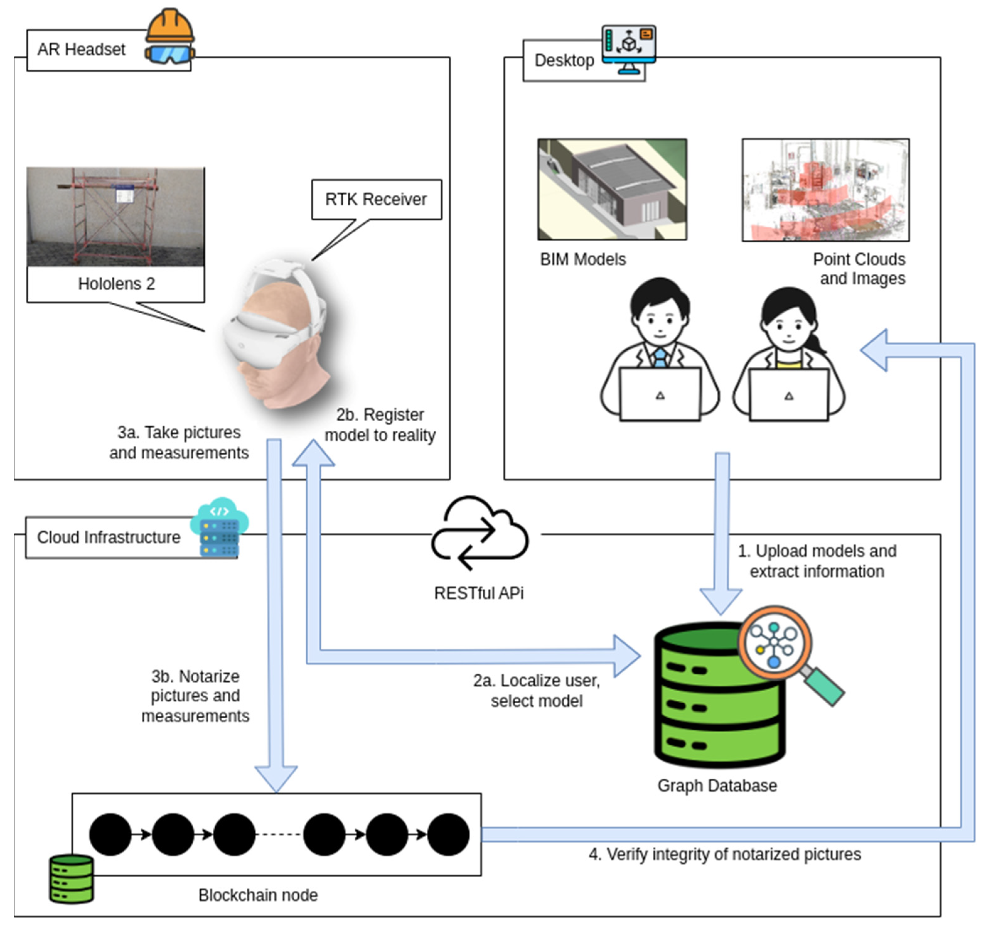
2.1. The System Architecture

The platform architecture was designed as a cloud platform made of several services and an AR client (Figure 1). The platform works as a hub connecting decentralized resources and processes, which facilitates data processing, storage, and distribution by means of RESTful APIs. It is able to monitor the execution of processes on the server side, as well as on the client side, and can invoke smart contracts that are responsible for notarizing relevant tasks of tracked processes, along with their metadata.
More specifically, the platform hosts the following services:
  • Data storage;
  • GNSS-based AR registration engine;
  • Image-based AR registration engine;
  • Engine switcher;
  • Notarization engine.
Thanks to the above-mentioned services, the platform can host, localize, and even align BIM models with images and point clouds within a common, bi-directional, geospatial context. In one method, the information hosted in the platform can be sent to already aligned AR devices; using the other method, pictures collected on-site through AR devices can be sent to already aligned with respect to BIM models on the platform. The data storage environment is responsible for storing and managing structured (e.g., IFC files) as well as unstructured (e.g., images) data. This facilitates accessibility to AR applications through dedicated clients. The digital models developed and stored in the platform to manage health and safety are described in Section 2.2. Then, Section 2.3 deals with the registration technology, including the geolocation feature that allows virtual assets and features to be mapped accurately against their corresponding real-world locations (based on WGS-84), thus facilitating integration between the virtual and physical realms. Indeed, one of the key responsibilities of the AR cloud platform is to manage the seamless alignment of processes for both outdoor and indoor surveys [35]. Basically, the correct positioning of images within the platform requires the estimation of the absolute world coordinates of the acquisition point, along with the accurate rotations for a full 6-Degree-of-Freedom (6-DoF) pose estimation. The two registration engines hosted by the platform are specialized for outdoor and indoor environments, respectively. The GNSS-based AR registration engine relies on the combination of GNSS-RTK and the IMU system of AR devices and is tailored to work in open spaces, dealing with the absence of reliable reference points and coping with large and dynamic environments. The image-based AR registration engine is based on artificial vision algorithms and designed to perform localization in environments characterized by restricted access to GNSS signals. It leverages features like point clouds and pictures to achieve an accurate positioning. In this subsystem, Convolutional Neural Networks (CNNs) [36,37] have been applied for simultaneously predicting local features and global descriptors for accurate 6-DoF localization. Finally, the engine switcher serves as a rule-based engine integrating the GNSS-based and image-based AR registration technologies. Depending on the availability of the GNSS signal, it dynamically switches between the outdoor and the indoor registration approaches to maintain a consistent and uninterrupted AR experience. The combination of the four elements allows the system architecture to deliver a robust marker-less AR system that can seamlessly switch between indoor and outdoor scenarios.
Section 2.4 concerns the platform’s services responsible for compiling smart contracts from BPMN diagrams, deploying such smart contracts on selected blockchains, and notifying the smart contracts of the new datasets collected in the field. It notarizes their metadata, too. Some representative scenario of steps worth being notarized using the compiled smart contract could be a newly uploaded IFC/BIM model, as well as the actions performed on-site by a safety inspector at a construction site who is required to report the status of the site and any other details relevant for safety assessment.

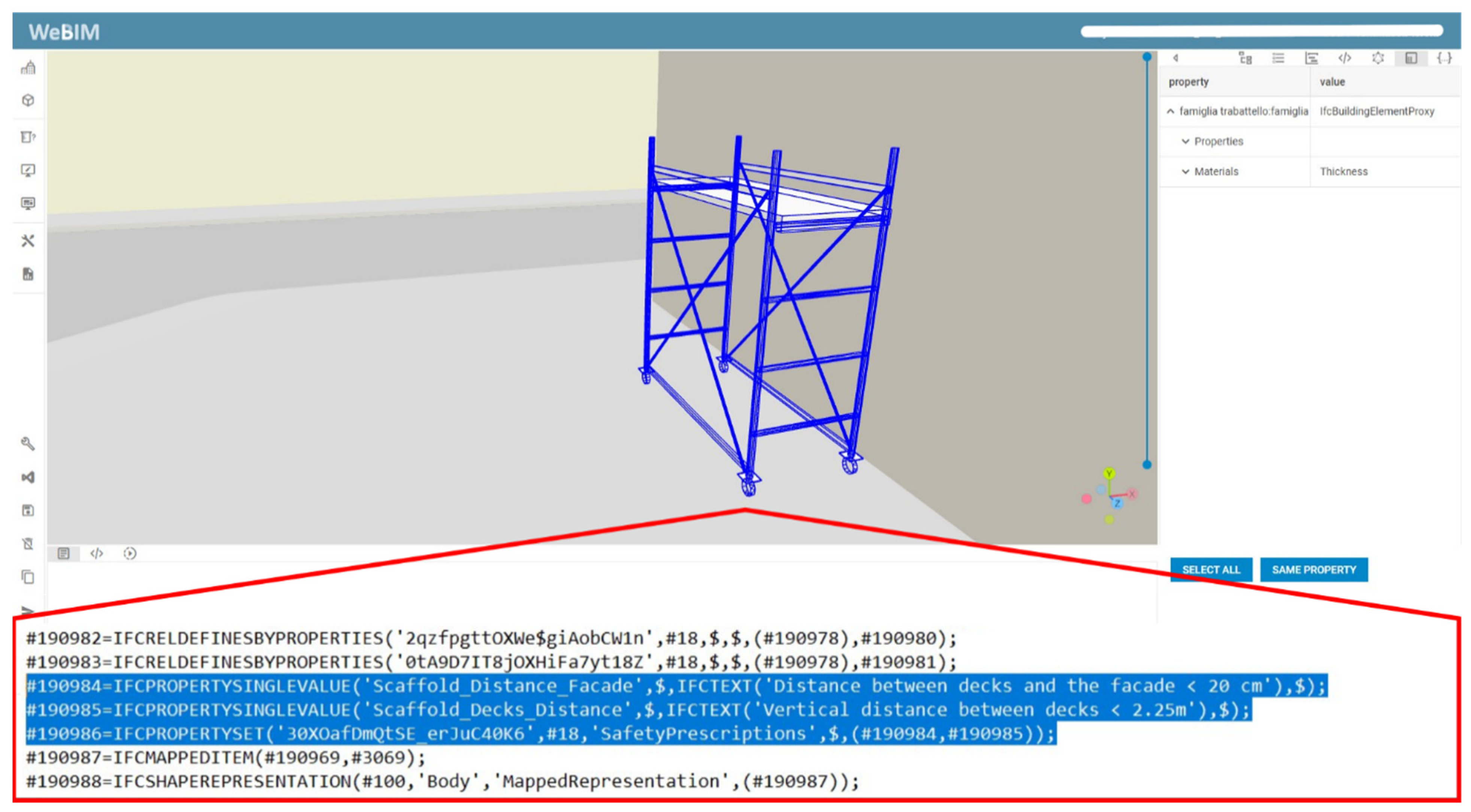
2.2. Digital Model of the H&S Plan

As extensively discussed in Section 1.2, at present, there is no fully developed digital form of a H&S plan due to the absence of standardized protocols capable of representing and exchanging safety management information in open formats. In the Italian context, construction site safety is regulated by the Safety and Coordination Plan (PSC), a document that constitutes the national transposition of the H&S plan introduced by European Directive 92/57/EEC. The PSC encompasses a structured set of regulatory provisions aimed at hazard prevention, addressing aspects such as the provision of safety equipment and procedures, the implementation of mandatory inspections, and the configuration of the construction site layout. These provisions are tailored to the specific construction site under consideration, taking into account the nature of the industrial activities being undertaken and the associated risks (e.g., burial during excavation, falls from height, drowning). Compliance with the PSC, in terms of both site conditions and operational safety practices, is subject to periodic inspections conducted by labor authorities. A critical limitation of the PSC is that its content is not systematically structured according to the chronological sequence of construction phases. This lack of temporal organization complicates consultation for both site operators, who are responsible for implementing safety measures, and inspectors, who are tasked with verifying compliance [38].
Natural Language Processing (NLP) is a discipline that has taken off in recent years thanks to the huge development of neural networks for text recognition and information extraction from documents. Consequently, it has been successfully applied in the construction industry, and several surveys have documented this effort [39,40,41,42,43]. Each of them reviewed a large number of case studies where NLP was used to support several activities, in particular in the domain of managing safety and checking compliance of project designs with respect to existing regulations.
To enhance the accessibility of the PSC and streamline inspection procedures, an analysis was conducted to identify all verifications that can be effectively modeled through BIM authoring software, with particular focus on those requiring visual and/or dimensional assessments. Based on this analysis, text-based parameters encapsulating safety prescriptions for specific site installations were defined and subsequently exported using dedicated property sets in the open IFC format. This approach facilitates interoperability with other digital technologies, such as AR. The technical methodologies for BIM modeling and IFC export will be elaborated in greater detail in Section 3.3. By adopting this method, the geometric models of site installations serve not only as spatial placeholders but also as information carriers, embedding parameters related to mandatory inspections. Prior to full-scale experimentation, preliminary validation was conducted on selected case studies, specifically cranes, scaffolding, and site fencing. The parameters embedded within these models were successfully exported using the property set illustrated in Figure 2. The actual experimentation was conducted by modeling a mobile scaffold, as this can be partially associated with a conventional scaffolding system while maintaining a manageable level of complexity given the available resources.

2.3. AR Registration Engines for Indoor and Outdoor Alignment of Virtual Models

The hybrid registration system developed and tested in this paper is made of three components: the outdoor AR navigation, the indoor AR navigation, and the switch engine [35].
The first component, that is, the outdoor AR registration engine, relies on the combination of two localization systems. The first one is the RTK GNSS, while the second one is the Inertial Measurement Unit (IMU) included in the “HoloLens2” headset, that is, its built-in inertial tracking system. It was designed to be able to deal with the lack of reference points and the large size and dynamicity of open spaces. The placement of world-referenced 3D BIM objects represented in BIM models into Hololens2’s local frame is achieved through four steps: (i) aligning the local frame with the north direction; (ii) adjusting the object position; (iii) adjusting the object altitude; and (iv) placing objects based on the distance from the observer. More specifically, the first step for the outdoor engine involves acquiring initial samples from both the RTK and IMU systems. The RTK system computes absolute 3D coordinates of the body frame, while the IMU computes local 3D coordinates and rotations of the body frame. Then, the north directions of both systems are aligned through a coordinate transformation to compensate for the arbitrary orientation of the HoloLens2’s local frame. The second step involves another transformation, which is carried out while the system worn by operators moves around: as long as an observer moves far from the origin, the local reference is translated in the new position and the 3D objects are repositioned with respect to the new reference system. The third step entails the adjustment of the altitude, which is estimated from GNSS records. Each time a GNSS measure is acquired concerning the observer’s altitude, its height in the local coordinate system is stored for later use as the height of the origin of the local frame. Hence, the altitude of the local frame and the altitude of an object can be computed and moved vertically to match their correct height above the ground. As a result, the object is placed based on the observer’s position, which is the fourth step listed above.
The second component is the indoor AR registration engine. It integrates Convolutional Neural Networks (CNNs), which simultaneously predict local features and global descriptors and have been applied for accurate 6-DoF localization [36]. In order for this approach to be feasible, a preliminary on-site survey must be carried out with a camera and LiDAR scanner. As a result, a point cloud and respective aligned photos of the indoor environment must be collected.
Basically, pictures from the current view (i.e., the so-called query image) are compared with pictures referenced to the point cloud, which are both stored in the BIM cloud platform described in Section 2.1 and called “WeBIM”. Hierarchical Feature Network (HF-Net) technology is implemented to carry out the image comparison at each HoloLens2 registration call. It consists of a coarse search, including global descriptor matching between the query image and the reference images and a finer search based on local descriptor matching. This second matching involves a comparison between the query image’s 2D keypoints and the point cloud’s 3D points visible in reference pictures. Finally, a 6-DoF pose estimation of the query image is carried out by solving the Perspective-n-Point (PnP) problem [44]. The estimated pose is the result of the rotation and translation vectors that allow for transforming 3D points expressed in the real-world coordinate system into the camera coordinate system. The parameters of this vector enable the indoor AR registration of each HoloLens2’s gaze.
The third component is the switch engine, which is a rule-based engine that assesses the availability of either GNSS signals, pictures, or both. Depending on the result of this check, it dynamically switches between the two registration approaches to maintain a consistent and uninterrupted AR experience. It acts differently according to three possible scenarios: (i) use of RTK technology only, which is feasible in outdoor scenarios; (ii) RTK combined with pictures/point clouds, which is still feasible outdoors; and (iii) use of pictures/point clouds only, which is feasible in indoor scenarios.

2.4. Blockchain

In order to trace the execution of actual processes developing at the construction site, Solidity smart contracts are deployed on DLTs of the Ethereum family. This decision is motivated by several factors: Ethereum blockchains are public blockchains; thus, the infrastructure is available to all actors willing to employ it. In addition, it is based on open-source tools that have been tested by thousands of users over time running billions of transactions in production and test environments; thus, it can be considered a well-established technology for the distributed computing and secure storage of information. Finally, the Solidity language is an expressive programming language easily adaptable to encode general-purpose needs and complex algorithms, as in the applicative case under consideration, where business processes requires runtime monitoring and enforcement. This is a notable advantage, especially contrasted with other kinds of smart contracts like in the Bitcoin blockchain, where restrictions on the expressiveness of the smart contracts make them well suited for financial transactions but not for encoding general-purpose algorithms.
In the experiments, Smart contracts allow for the encoding of state transition systems to describe the datasets and the metadata collected in the field through surveying procedures.
The combination of smart contracts and distributed ledger technologies allows BIM-based digital twin platforms and methodologies to fulfill two very important requirements of digital twins: availability and integrity of critical information. In this regard, every relevant change of state happening on the construction grounds can be encoded by a state transition in the smart contract monitoring the environment. The latter replaces the current state of the smart contract with a new one, and the DLT supporting the smart contract itself takes care of propagating the change across all the nodes so that, worldwide, all the nodes share the same view of what happened on the construction grounds.
In the presented methodology, smart contracts are compiled automatically starting from a formal description of the processes to be monitored, e.g., using BPMN as a standard notation for representing industrial processes. The BPMN standard is also used in several applications in the construction industry, and some solutions are already exploring their integration with smart contracts and blockchains for tracing and enforcing process executions [30,45,46,47]. The automatic compilation of smart contracts minimizes the risk of introducing modeling faults during the stage of encoding the actual work process as a state transition system at the core of the smart contract itself or logical errors during the programming activity.
As explained in Section 1.2.3, ChoEn and other available tools combining smart contracts on blockchains and BPMN descriptions of industrial processes do not yet integrate decentralized file storage solutions like IPFS. Thus, experiments were conducted by defining choreographies that would allow the system to notarize incomplete files and digital artifacts (e.g., survey pictures, PDF reports…) with a digital signature generated by such files called hash digest. This is a standard approach used by state-of-the-art solutions in the field [48].
For the sake of consistency, let us recall that a hash digest of a file is a unique string of alphanumerical ASCII characters obtained by applying a so-called hash function to the content of the file. Mathematically, a hash function has the following desirable properties:
  • It maps two different arrays of bytes to very different hash digests in a pseudo-random manner.
  • It is not possible to predict how a byte changed in the file content can reflect in the hash digest of the updated file.
  • It is not possible to recover the file content starting from the hash digest.
  • A hash function can be computed very efficiently (they have linear computational complexity, which is considered very good in practical applications).
  • The probability of two different files mapping onto the same hash digest is negligible.
These features make hash functions and hash digests popular tools in order to guarantee the integrity of files that should be accessed a long time after they are initially stored or since the last update.
A typical workflow for notarizing hash files in blockchain smart contracts for the purpose of ensuring the integrity of the files themselves is as follows:
  • When a file F is stored, the hash digest dF is computed.
  • The file F is sent to a cloud storage provider and made available at hyperlink lF.
  • The hash digest dF is sent to a smart contract by passing it as an input parameter when invoking a method in the smart contract itself; this returns a transaction signature tsF confirming that the information has been wrapped in a transaction and notarized by a block of the blockchain.
  • The hyperlink lF, the transaction signature tsF, and the hash digest dF are stored in a database managed by the application, together with the name of file F.
  • When accessing file F after a period of time, the application downloads file F using the hyperlink lF and, before showing it to the user, again computes the hash digest dF′ of file F.
  • If the two hash digests dF′ and dF indeed match, the application shows the file F with a confirmation (e.g., a special mark) certifying that it has not been tampered with since the file was last updated; otherwise, the application can choose to either make the file available to the user showing that an exception arose in the integrity verification procedure or to prevent the user from downloading the file content. The latter, a more radical approach, may be justified in contexts where absolute adherence to security policy must be ensured when accessing critical information.

3. Results

3.1. Design of Experiments

In order to verify the feasibility of the proposed method, a series of tests was designed and carried out in the Digital Construction Capability Centre (DC3) laboratory of Polytechnic University of Marche.
The procedures to be tested were as follows:
  • Indoor image collection and recognition verification by alignment;
  • Verification of outdoor registration via GNSS;
  • Verification of the correct display of prescriptions supporting outdoor and indoor inspections;
  • Verification of notarization of the images collected via blockchain.
The first preliminary test also had the purpose of setting up the system as an initial collection of images of the space, which is necessary for subsequent alignments. This test, described in detail in Section 3.2.1, was also aimed at verifying that in a visually poorly characterized environment (e.g., white walls without particular markings or distinctive signs, gray floor without demarcations), the system still returned acceptable precision and recall values and was therefore able to recognize the environment.
The verification of the outdoor recording via GNSS recorded the correct functioning of the positioning via the antenna data without being able to carry out an evaluation by modifying the parameters as explained in Section 3.2.2.
For the verification of the correct visualization of the indoor and outdoor data, the inspection procedure was reproduced from the BIM of the laboratory to represent the construction site. Figure 3 shows the BIM model loaded into the WeBIM platform.
During the inspection simulation, the visibility and readability of the holographic prescriptions and the user-friendliness of the prior system were evaluated. This part of the test is presented in Section 3.3, Section 3.4 and Section 3.5.
Finally, the verification of the notarization of pictures tested the specific aspect of the delay time of the method implemented for the execution of transactions. Notarization is discussed in Section 3.6.

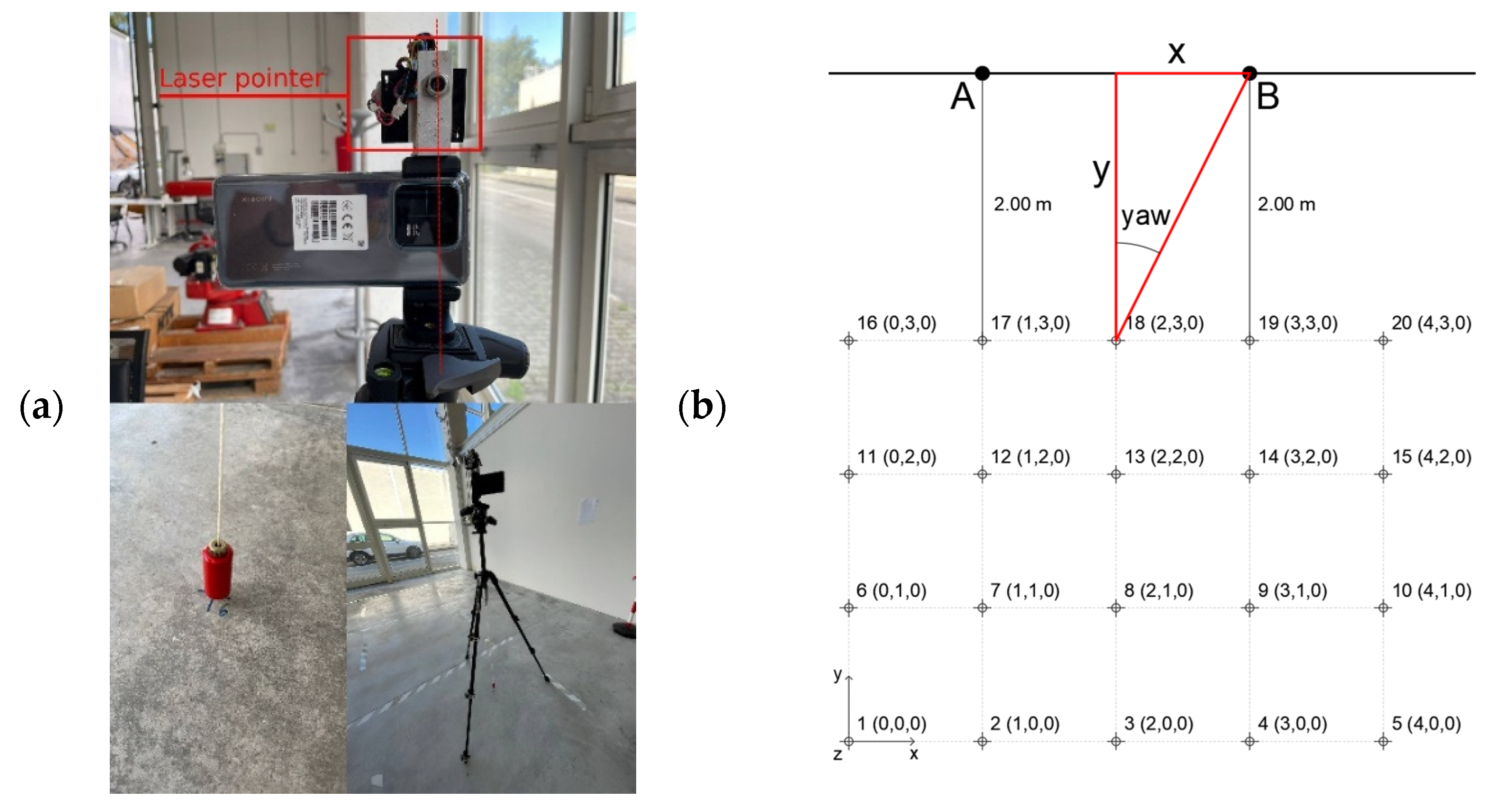
3.2. Test of the Accuracy of the Registration Engine

3.2.1. Indoor Image-Based Registration Test

To analyze the spatial registration accuracy from both qualitative and quantitative perspectives, an image-based registration evaluation was carried out using a smartphone, demonstrating the viability of cost-effective and infrastructure-free equipment for construction site applications. For image acquisition, an orthogonal grid with a 1 × 1 m mesh was systematically arranged on the floor within the designated testing area. The grid measured 5 m in width and 4 m in height, creating 20 intersection points with predefined spatial coordinates (x, y, z), as illustrated in Figure 4b. To investigate variations in alignment accuracy, six distinct scenarios were established for the image-based indoor registration test. These scenarios explored the impact of different factors, including the number of photographs captured during the mapping phase, the number of key points extracted for feature mapping and matching, and the camera calibration technique used (Table 1).
The images were taken using a smartphone mounted on a tripod, which was equipped with a laser pointer and a plumb line to ensure precise positioning. The smartphone used during the test was equipped with a 50 MP sensor, paired with a 7.79 mm focal length and a wide aperture of f/1.9, allowing for better light intake and depth-of-field control. During the experimentation phase, the images were captured at a resolution of 4096 × 3072 pixels. The shutter speed and ISO sensitivity were automatically adjusted by the device according to ambient lighting conditions, leveraging the smartphone’s exposure system to optimize each shot. Prior to each capture, the tripod was carefully leveled using its built-in bubble levels to maintain alignment. The tripod’s position relative to the designated grid points was verified using the plumb line suspended beneath the tripod head, guaranteeing a high degree of accuracy. At each grid intersection, two images were taken: one oriented toward Point A and the other toward Point B. These reference points were arbitrarily selected and remained fixed throughout the procedure. The laser pointer mounted on the tripod ensured precise and consistent alignment with these points. Consequently, a total of forty photographs were obtained. Of these, twenty images were used for site mapping, while the remaining twenty were localized based on the mapped references and analyzed to evaluate the registration accuracy.
Establishing a reference grid enables a direct comparison between the results obtained through the registration process and the actual positional values (tvec) and camera orientation (yaw angle). The tvec parameter is a {x, y, z} vector representing the precise location at which the image is captured, while the yaw angle denotes the camera’s orientation on the horizontal plane (see Figure 4). Following data collection from the logs generated at the conclusion of the image-based registration process, the pose estimation error is quantified using the tvec error. This metric is generally defined as the vector difference between tvec estimated, derived from the registration logs, and tvec real (Equations (1) and (3)), which is obtained based on the pre-established reference grid used during image acquisition. The same methodology applies to the calculation of yaw error, which measures deviations in the estimated camera orientation relative to the actual reference values.
tvec real = {x,y,z}grid
yaw real = arctan x/y
tvec error = tvec estimatedtvec real
yaw error = yaw estimatedyaw real
The collected data related to localization errors (tvec error) and camera orientation errors (yaw error) (Figure 5) were reprocessed in terms of percentage recall (5). This approach highlights, for each individual scenario, the proportion of photographs that were registered with sufficient accuracy relative to the total number of images acquired and processed during the registration campaign. The criterion used to determine whether a photograph was correctly registered (True Positive) is based on the maximum permissible errors for tvec error and yaw error, as defined by the LaMAR benchmark [49]. Specifically, all images with a tvec error below 10 cm and a yaw error below 1° were considered to have been registered with adequate accuracy. Subsequently, the threshold was progressively lowered to examine the performance of different scenarios under stricter error tolerance conditions applied to the registration engine. In particular, the revised reference thresholds for tvec error/yaw error were set at 5 cm/1° and 5 cm/0.5°.
Recall (%) = (True Positive)/(True Positive + False Positive)
Figure 6 presents the recall values for each scenario. It can be concluded that, in general, the most effective approach is to use reduced parameters in combination with a high-resolution camera calibration (DC3_5-6 scenarios), as this optimizes computational efforts without significantly compromising alignment accuracy. As expected, scenarios that employed twenty images for the mapping procedure exhibited slightly higher recall values than those using only ten images (+9.47%, +13.68%). However, the results suggest that rather than the number of images alone, the primary factor influencing registration accuracy is the presence and quality of visual features within the images.

3.2.2. Outdoor GNSS/RTK-IMU Registration Test

In this section, the results of the outdoor image acquisition conducted using the high-precision hybrid GNSS/RTK-IMU system are presented. It should be noted that, unlike the image-based registration tests, no systematic or quantitative experiments were conducted to allow for a numerical comparison between the achieved alignment quality and the actual positioning of the photograph. The primary reason is that, as GNSS-RTK/IMU technology relies on satellite signals rather than image processing, an accurate evaluation would require significantly more extensive testing, in which multiple environmental factors (e.g., signal quality, distance from the RTK antenna, and the presence of vegetation or buildings) are systematically varied. These tests are planned for future research. The accuracy of the alignment between holograms and real-world elements can be assessed from a visual and qualitative perspective. In terms of orders of magnitude, the results obtained were considered sufficiently accurate for the objectives pursued through this research work.
To analytically confirm that the image has been correctly geolocated and registered, the EXIF metadata embedded within the image file is examined. Specifically, it can be observed that the “Image Description” field contains the geographical coordinates of the capture point, the localization accuracy (14 mm), and the pose parameters {qx, qy, qz, qw}, all of which are successfully stored in JSON format and are reported as follows:
{“timestamp”:“2024-09-26T13:14:56.381+02”,
“wgs84”:{
“latitude”:43.585798883760582,
“longitude”:13.513506528899345,
“altitude”:176.599655,
“altitudeMSL”:133.59465,
“horizontalAccuracy”:14.0,
“verticalAccuracy”:14.0,
“course”:0.0,
“azimuth”:301.110474},
“enu”:{“x”:0.191426814,
“y”:1.7916981,
“z”:1.73365486,
“qx”:0.238131449,
“qy”:0.478123665,
“qz”:-0.76299727,
“qw”:-0.3640416}}
Thanks to the EXIF metadata embedded in the images stored within the platform database, these images can be retrieved at a later stage while maintaining their alignment with the model. This functionality is particularly valuable in large-scale and complex construction sites, where tracking the precise location and orientation from which inspectors capture images can be challenging.

3.3. Experimental Tests

The experimental apparatus utilized for testing was scaffolding. Given the multifaceted nature of safety assessments, numerous parameters require evaluation. For the purpose of laboratory experimentation, two specific parameters were selected to replicate conditions observed during site inspections: (i) the distance between the scaffold and the adjacent wall and (ii) the spacing between consecutive scaffold working platforms. As a permanent scaffold was not available in the laboratory at the time of testing, a mobile scaffold was employed as a substitute. The digitization process was conducted using BIM to accurately represent the object’s visual characteristics, geometric configuration, precise spatial positioning, and the prescriptive criteria designated for field verification.
The scaffold was modeled in BIM using an IfcBuildingElementProxy, while the requirements to be verified were defined as parameters within a dedicated property set. This property set was renamed SafetyPrescriptions, with specific attributes assigned to facilitate verification. The first parameter, Scaffold_Distance_Facade, was designated to ensure compliance with the minimum required distance between the scaffold and the adjacent vertical surface (e.g., a wall). The second parameter, Scaffold_Decks_Distance, was introduced to verify the correct spacing between scaffold decks. Once the geometry and associated information were modeled, the data was exported in IFC format (Figure 7) and subsequently uploaded onto the WeBIM platform, as referenced in 2.1. This platform enables the seamless streaming of information to the application running on the HoloLens device. The simulated inspection was conducted under two distinct scenarios: (1) indoor and (2) outdoor. To enhance the clarity of the procedural demonstration, two operators were present on-site, each equipped with a HoloLens device and simultaneously utilizing the same application. This setup allowed for the capture of images in which both the operators and the holographic projections are visible, as illustrated in Section 3.4.

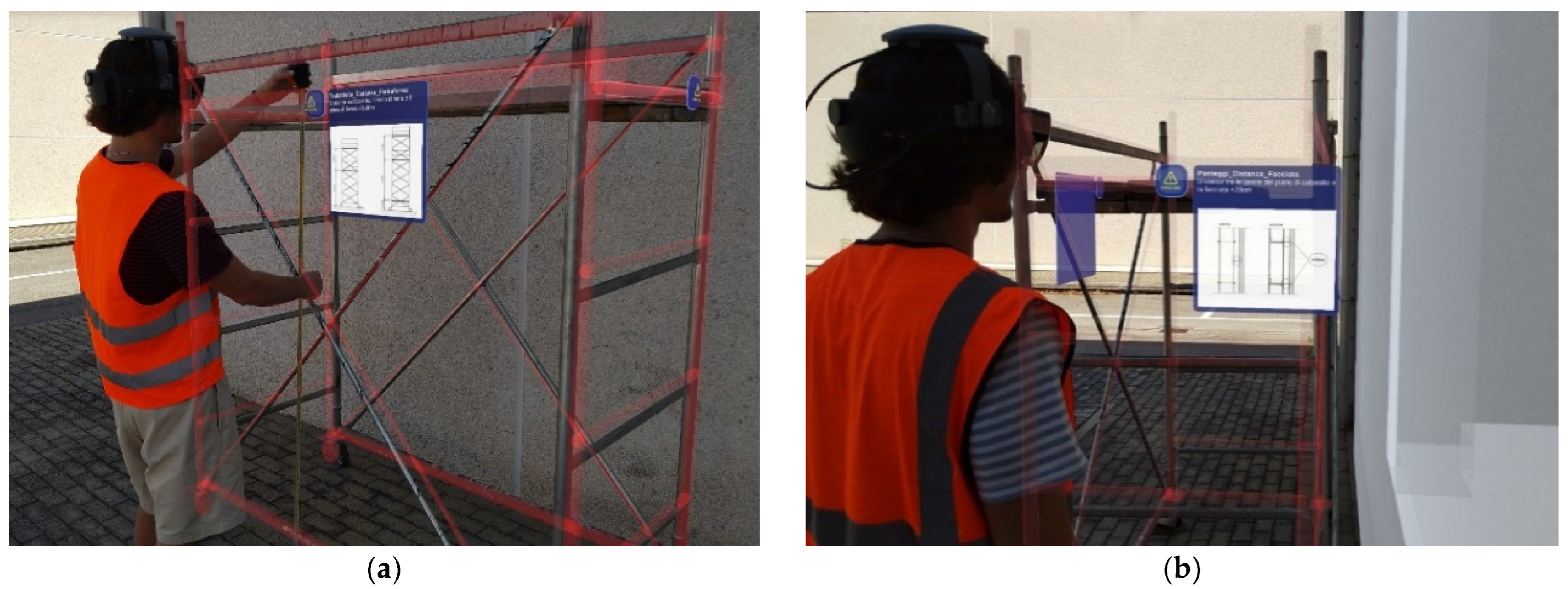
3.4. Visualization of the BIM Model and Checking of Annotated Safety Prescriptions

In both scenarios, the process began with the safety supervisor entering the construction site and activating the HoloLens 2 headset to initiate the on-site verification of safety requirements. The next step involved navigating the registration application’s interface to access a complete catalog of available BIM models within the platform, including those incorporating safety-related data. Once the relevant model—specifically, the laboratory environment—was selected, the supervisor accessed the corresponding BIM representation and launched the AR registration engine. The switch engine autonomously determined whether the user was operating indoors or outdoors. Figure 8a provides the perspective of the second operator, showing the first operator examining the model and the indoor scaffolding, aligned using HF-Net technology and automatically activated by the switch engine. This process was made possible by the prior acquisition and storage of point cloud data and images of the laboratory, collected through the GeoSLAM Backpack Vision system and subsequently uploaded to the WeBIM platform. Figure 8b, on the other hand, presents a first-person perspective of the safety supervisor performing the outdoor inspection, utilizing geospatial data retrieved from the RTK receiver embedded in the HoloLens 2, in combination with the Inertial Measurement Unit (IMU). As soon as the HoloLens headset emitted a ray that intersected a BIM object linked to an annotation containing safety prescriptions, the relevant annotation was displayed within the HoloLens 2 application. This feature allowed the supervisor to receive real-time assistance in identifying and validating the safety measures specified in the digital Health and Safety (H&S) plan. Once the verification process was completed, an image was captured and uploaded to the WeBIM platform for notarization and further analysis. Figure 9a, again from the second operator’s perspective, illustrates the on-site validation of level heights in the outdoor environment. Figure 9b highlights the annotation regarding the distance between one side of the scaffolding and the adjacent wall in the outdoor scenario.
In addition, Figure 10 presents the full safety inspection workflow alongside the WeBIM platform interface related to the final verification steps. The left-hand screenshot displays a measurement recorded in the back office within the WeBIM platform, accessible even remotely, whereas the right-hand screenshot visualizes the blockchain-based notarization process. Successful notarizations are marked in green, whereas unsuccessful attempts—such as instances where an image was altered after the initial notarization—are indicated in red.
Finally, an assessment of the overall preliminary safety system was made through a comparison of its features against those of traditional safety systems with respect to a set of criteria that the literature recognizes as relevant factors hampering the application of safety measures at construction sites. More specifically, a wide survey carried out through 447 questionnaires targeting operators in the construction industry (spanning from construction workers to front-line and senior managers) revealed that five main factors challenge the effective deployment of safety measures at construction sites, namely, (i) human factors; (ii) equipment factors; (iii) environmental factors; (iv) management factors; and (v) technical factors [50]. Every factor represents a common underlying dimension including several items, clustered as shown in the two left-most columns of Table 2. The third column indicates those items affected by the safety system presented in this paper, showing that it is beneficial for 11 out of 29 items, which is around 40% of the total number of items. The right-most column of the table reports what enhancements the safety system determines over traditional methods, which span across all the dimensions and are mostly concerned with a better analysis of risks and mitigation actions in the digital H&S plan, along with a more effective inspection protocol and accountability.

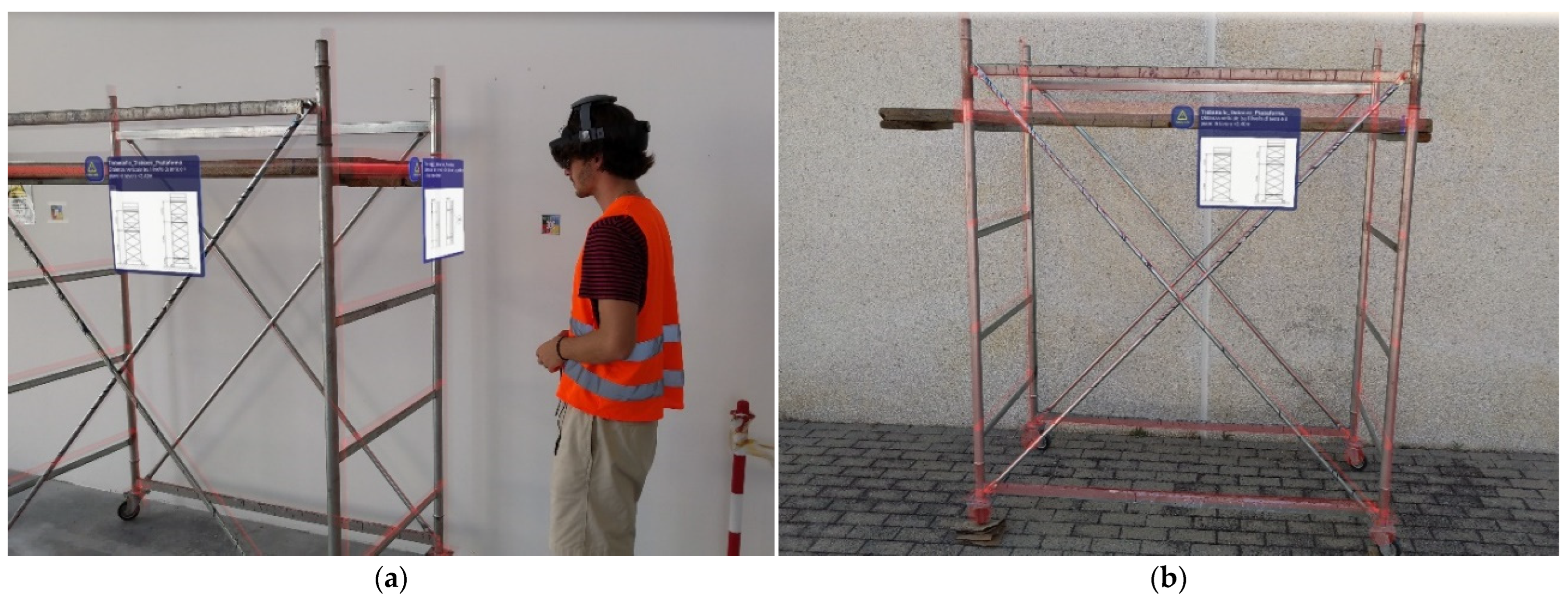
3.5. Alignment of the MR Hologram, Uploading of Pictures, Alignment of the Pictures in the Platform, and Measurement of Distances

When the WeBIM Platform is accessed by the inspector via the web-based Graphical User Interface (GUI), it transmits a list of available BIM models.
After selecting a model from the list, the inspector proceeds to upload the corresponding images. For each image, the interface displays either a green check mark or a red alert. A green check mark indicates that the hash computed from the uploaded image matches the hash stored in the corresponding blockchain transaction, confirming its integrity. Conversely, a red alert appears if the image is not linked to any blockchain transaction, if the transaction lacks an associated hash, or if the computed hash does not match the one recorded on the blockchain. This verification mechanism enables the web GUI to assure the inspector that the integrity of the stored information has remained unaltered since its initial recording. In the event of a mismatch, the user can only retrieve the original hash stored in the blockchain, as it is well established that reconstructing the original file from its hash is not possible. At this stage, the inspector utilizes the measurement tool available in the web GUI to create a new measurement. Once completed, the user confirms the measurement, which is then added to a dedicated list. Each newly stored measurement undergoes a notarization process. Unlike image verification, there is no need to pass a hash of the stored measurement to the notarization smart contract; instead, only metadata, formatted as a serialized JSON object, is recorded. As a result, the web GUI can present the inspector with a list of stored measurements (Figure 10), each accompanied by either a green check mark or a red alert. The verification status depends on whether a corresponding transaction exists in the blockchain that reports the same measurement retrieved from the database.

3.6. Results and Tests on Smart Contracts

Let us focus here on operations involving smart contracts on the blockchain. It is possible to divide operations in two main stages: compilation of smart contracts and execution of smart contracts. During compilation, for each choreography to be traced, the ChoEn tool generates two smart contracts that share the responsibility of tracing the execution of processes developing on the field and for returning the picture metadata in the current survey, including the picture name, its size in bytes, and of course its hash digest at the time when it was notarized. This choreography is depicted in Figure 10. The main actors are the operator, the WeBIM platform, the notarization engine, and four exclusive gateways. The generated smart contracts require a total of 82,518 bytes and ten-fold simulation of the deployment stage. The tests were conducted on two Ethereum test networks called Sepolia and Holesky. On the former network, the average deployment time was 31.96 s (min. 12.13 s, max. 128.95 s, std. dev. 28.82 s), while on the latter, the average deployment time was 28.85 s (min. 16.33 s, max. 70.80 s, std. dev. 16.22 s).
During the simulated experiments, several pictures were collected, two of which are presented in Figure 10. The hash digests were computed using the SHA256 function. For example, the hash digest of the image on the right in Figure 10 is 2bea2bab10a4adc9e3de5b2cd0281ccddd8d6771d8e576825cc8e57aa941a311.
The 20 simulated executions of the smart contract notarization were repeated on both networks, Sepolia and Holesky. The notarization step on the former network took on average 26.35 s (min. 13.19 s, max. 95.24 s, std. dev. 22.64 s), while on the latter network, it took on average 20.66 s (min. 6.31 s, max. 105.52 s, std. dev. 16.47 s).
The experimental data is summarized in Table 3.
As is evident from the collected data, the notarization step, and more specifically, the validation of transactions induced by smart contract method invocations, introduce considerable time delays that must be treated asynchronously in order to allow the user to continue the survey steps and not block operations in the field. For this reason, the client is designed to manage a queue of pending transactions waiting to be validated, and as soon as these transactions are validated, the transaction hashes are stored together with all the information, as recommended by the workflow described in Section 2.4. On the contrary, in the event of a transaction that cannot be validated, the user is informed and he/she can decide to retry the notarization step once more on the same picture or discard the picture associated with the failed notarization transaction.

4. Discussion

The research questions introduced in the first section and addressed in this study are as follows:
  • RQ1: Can safety prescriptions be efficiently represented in BIM models?
  • RQ2: Can augmented reality be the right technology for representing information on-site?
  • RQ3: Is the proposed procedure a feasible way to conduct inspections?
Regarding research question RQ1, it was successfully answered, albeit with some limitations that will be discussed. The focus was on modeling safety installations that are set up on construction sites (e.g., scaffolding) and large machinery that also requires installation (e.g., cranes). This modeling currently suffers from the inability to be anchored to the IFC standard, which does not yet include specific elements representing safety-related aspects. However, the ability to model the site layout within the same software used for Building Information Modeling (BIM) facilitates the digitalization of safety processes.
Furthermore, this type of modeling enables an effective visualization of data since geometry—whether detailed or simplified—is an integral part of the model. This study also analyzed which safety prescriptions can be digitalized and made accessible and which, on the other hand, require a data-linked approach. One aspect not yet explored, which could be part of future developments, is the modeling of work areas and traffic routes. The spatial visualization provided by BIM is undoubtedly one of its key advantages, and when combined with modeled safety installations and equipment, it contributes to a comprehensive definition of the construction site layout.
Lastly, concerning RQ1, BIM currently lacks the ability to manage certain safety elements, such as protective devices, resources, and procedures. To address these aspects, external connections to the 3D model will need to be developed while maintaining reference to the representation of the construction site throughout its various phases.
The combination of BIM and AR for on-site data visualization has demonstrated its feasibility. Model streaming and alignment have yielded excellent results. The holograms of safety installations serve as placeholders for information, effectively drawing the inspector’s attention to the specific aspects that need verification, thereby guiding the inspection process. Additionally, the ability to take photos and upload them to the platform—where they can be measured once overlaid with the BIM model—enables remote verification and allows inspection data to be retrieved at any time.
The notarization of this data through blockchain technology ensures that it cannot be altered over time, making it a reliable reference in the event of incidents. For these reasons, RQ2 and RQ3 have also been satisfied, albeit with some limitations. The next steps in validating the procedure will require involving industry professionals to gather extensive feedback on the usability of the proposed tools and technology.
Regarding the technology itself, the requirement of an augmented reality headset could represent a barrier to its adoption. Therefore, the system should also be tested on more widely available devices such as smartphones and tablets to ensure accessibility and ease of use.
However, the system presents some limitations:
First and foremost, the IFC format does not provide security-specific element classes and forces data to be entered as generic classes. This can lead to greater difficulty in querying information. In addition, not all types of prescriptions can be conveniently placed in object parameters.
The procedure requires the training of operators who would like to use it and the cooperation of the operator/inspector in order to collect data and images.
Finally, augmented reality outdoors, especially in some lighting conditions, becomes difficult to enjoy. In addition, the use of viewers such as the HoloLens on the construction site is difficult to pursue.
It should also be mentioned that the proposed system and methodology have been tested with a simplified setting and in a controlled environment, so tests on construction sites are needed to demonstrate their feasibility of use even in complex environments.

5. Conclusions

The main objective of this paper is to work out new methods and to test novel technologies that can foster digitalization in the management of health and safety on construction sites. More specifically, a new approach to managing safety inspections on construction sites was worked out and preliminarily tested, facilitated by the use of mixed-reality technology and supported by DLTs. The approach assumes that the design process is based on BIM; hence, a prototype of a partially developed health and safety plan in an openBIM environment was showcased, despite the current lack of standardized data models and protocols for safety management. This was the source of information concerning safety prescriptions and feeding the work of supervisors on-site. Technically, the IFC model representing the layout of a construction site was enriched with entities and property sets embedding safety-related prescriptions. Then, a hybrid AR registration engine for on-site alignment of virtual models was refined and tested for the purpose of its application. The outdoor AR registration engine is based on the use of RTK GNSS, whereas the indoor AR registration engine exploits image comparison at each registration call through CNNs. Finally, a Solidity smart contract application deployed on DLTs of the Ethereum family was integrated in the safety inspection system to encode state transitions concerning datasets and metadata collected in the field as a result of survey procedures. The experimental results showed that the AR registration system aligns models within the required accuracy, as dictated by the LaMAR benchmark, which can allow supervisors to carry out safety checks by overlaying virtual models over the actual equipment deployed on-site. Outdoor tests showed that the parameters required in image post-processing were collected and resulted in the successful registration of virtual models in the laboratory tests simulating the inspection of a mobile scaffold. The time delays determined by smart contracts were considered acceptable as related to the number of transactions to be notarized during any safety inspection, on the order tens or hundreds of pictures. Operationally, thanks to the automated alignment of models, the information hosted in the platform within IFC models can be displayed on-site by supervisors, who can confirm the correct implementation of safety prescriptions thanks to the combination of the H&S plan, which is available as a virtual layer connected with the physical environment, and the evidence collected from the observation of the actual site arrangement. Once evidence has been collected, e.g., as pictures, it can be sent back to the platform and notarized in real time through the smart contract app integrated into the platform. In fact, such notarized information represents a proof of the level of application of actual safety prescriptions during the execution of construction works and provides the system with the critical properties of availability and criticality of the evidence collected during on-site safety inspections [51]. This paper emphasizes the importance of a call to action for the standardization of safety data in a BIM environment. Although the focus of this paper concerned safety inspection by supervisors, the development of safety-related standards, e.g., in the form of an upcoming version of IFC specifications [52], would enhance safety management overall and would enable the effective deployment of advanced technologies with related benefits, such as the AR/MR visualization and communication tools developed and showcased in this paper.

Author Contributions

Conceptualization, A.C. (Alessandra Corneli) and B.N.; Methodology, A.C. (Alessandra Corneli), A.C. (Alessandro Carbonari), F.S. and T.P.; Software, F.S.; Validation, F.S. and T.P.; Formal Analysis, A.C. (Alessandra Corneli) and A.C. (Alessandro Carbonari); Investigation, F.S. and T.P.; Resources, A.C. (Alessandra Corneli), A.C. (Alessandro Carbonari) and F.S.; Data Curation, A.C. (Alessandro Carbonari), F.S. and T.P.; Writing—Original Draft Preparation, A.C. (Alessandra Corneli), A.C. (Alessandro Carbonari), F.S. and T.P.; Writing—Review and Editing, A.C. (Alessandra Corneli) and A.C. (Alessandro Carbonari); Visualization, F.S. and T.P.; Supervision, B.N.; Project Administration, A.C. (Alessandra Corneli) and A.C. (Alessandro Carbonari); Funding Acquisition, A.C. (Alessandra Corneli) and B.N. All authors have read and agreed to the published version of the manuscript.

Funding

This research was partially founded within Task n. 4 “Education and Research” of the National Recovery and Resilience Plan (NRRP) and in particular component 2—investment 1.4, “Strengthening research facilities and creating “national R&D champions” on some Key Enabling Technologies” funded by the European Union NextGenerationEU research program named “Sustainable Mobility Center (Centro Nazionale per la Mobilità Sostenibile—CNMS)”, application code CN_000023—CUP I33C22001240001.

Data Availability Statement

Data are contained within the article.

Acknowledgments

The authors acknowledge the support and feedback from the chairs and co-chairs of CONVR 2024.

Conflicts of Interest

The authors declare no conflicts of interest.

References

  1. Rodrigues, F.; Antunes, F.; Matos, R. Safety plugins for risks prevention through design resourcing BIM. Constr. Innov. 2021, 21, 244–258. [Google Scholar] [CrossRef]
  2. Shanti, M.Z.; Cho, C.S.; Byon, Y.J.; Yeun, C.Y.; Kim, T.Y.; Kim, S.K.; Altunaiji, A. A Novel Implementation of an AI-Based Smart Construction Safety Inspection Protocol in the UAE. IEEE Access 2021, 9, 166603–166616. [Google Scholar] [CrossRef]
  3. Lingard, H.; Cooke, T.; Zelic, G.; Harley, J. A qualitative analysis of crane safety incident causation in the Australian construction industry. Saf. Sci. 2021, 133, 105028. [Google Scholar] [CrossRef]
  4. Wu, H.; Zhong, B.; Li, H.; Chi, H.L.; Wang, Y. On-site safety inspection of tower cranes: A blockchain-enabled conceptual framework. Saf. Sci. 2022, 153, 105815. [Google Scholar] [CrossRef]
  5. Ramos-Hurtado, J.; Muñoz-La Rivera, F.; Mora-Serrano, J.; Deraemaeker, A.; Valero, I. Proposal for the Deployment of an Augmented Reality Tool for Construction Safety Inspection. Buildings 2022, 12, 500. [Google Scholar] [CrossRef]
  6. Love, P.E.D.; Tenekedjiev, K. Understanding near-miss count data on construction sites using Greedy D-vine Copula Marginal Regression: A comment. Reliab. Eng. Syst. Saf. 2022, 217, 108021. [Google Scholar] [CrossRef]
  7. Yap, J.B.H.; Lee, W.K. Analysing the underlying factors affecting safety performance in building construction. Prod. Plan. Control 2020, 31, 1061–1076. Available online: https://www.tandfonline.com/doi/abs/10.1080/09537287.2019.1695292 (accessed on 30 June 2025). [CrossRef]
  8. Luo, Q.; Sun, C.; Li, Y.; Qi, Z.; Zhang, G. Applications of digital twin technology in construction safety risk management: A literature review. Eng. Constr. Archit. Manag. 2024, 32, 3587–3607. [Google Scholar] [CrossRef]
  9. Liu, J.; Duan, L.; Lin, S.; Miao, J.; Zhao, J. Concept, Creation, Services and Future Directions of Digital Twins in the Construction Industry: A Systematic Literature Review. Arch. Comput. Methods Eng. 2025, 32, 319–342. [Google Scholar] [CrossRef]
  10. Yan, H.; Liu, C.; Yang, X.; Feng, K. Real-Time Digital Twin–Driven 3D Near-Miss Detection System at Construction Sites. J. Constr. Eng. Manag. 2025, 151, 04025021. [Google Scholar] [CrossRef]
  11. Jang, D.H.; Roh, G.T.; Jeon, C.H.; Shim, C.S. Simulation-Based Optimization of Crane Lifting Position and Capacity Using a Construction Digital Twin for Prefabricated Bridge Deck Assembly. Buildings 2025, 15, 475. [Google Scholar] [CrossRef]
  12. Dobrucali, E.; Sadikoglu, E.; Demirkesen, S.; Zhang, C.; Tezel, A.; Kiral, I.A. A bibliometric analysis of digital technologies use in construction health and safety. Eng. Constr. Archit. Manag. 2024, 31, 3249–3282. [Google Scholar] [CrossRef]
  13. Jelonek, M.; Fiala, E.; Herrmann, T.; Teizer, J.; Embers, S.; König, M.; Mathis, A. Evaluating Virtual Reality Simulations for Construction Safety Training A User Study Exploring Learning Effects, Usability and User Experience. i-com 2022, 21, 269–281. [Google Scholar] [CrossRef]
  14. Akram, R.; Thaheem, M.J.; Nasir, A.R.; Ali, T.H.; Khan, S. Exploring the role of building information modeling in construction safety through science mapping. Saf. Sci. 2019, 120, 456–470. [Google Scholar] [CrossRef]
  15. Zhang, S.; Sulankivi, K.; Kiviniemi, M.; Romo, I.; Eastman, C.M.; Teizer, J. BIM-based fall hazard identification and prevention in construction safety planning. Saf. Sci. 2015, 72, 31–45. [Google Scholar] [CrossRef]
  16. Isatto, E.L.; An, I.F.C. Representation for Process-Based Cost Modeling. In Proceedings of the 18th International Conference on Computing in Civil and Building Engineering, São Paulo, Brazil, 18–20 August 2020; Springer International Publishing: Cham, Switzerland, 2021; pp. 519–528. [Google Scholar]
  17. Ding, L.; Li, K.; Zhou, Y.; Love, P.E.D. An IFC-inspection process model for infrastructure projects: Enabling real-time quality monitoring and control. Autom. Constr. 2017, 84, 96–110. [Google Scholar] [CrossRef]
  18. Zhang, S.; Teizer, J.; Lee, J.K.; Eastman, C.M.; Venugopal, M. Building Information Modeling (BIM) and Safety: Automatic Safety Checking of Construction Models and Schedules. Autom. Constr. 2013, 29, 183–195. [Google Scholar] [CrossRef]
  19. Park, J.; Kim, K.; Cho, Y.K. Framework of Automated Construction-Safety Monitoring Using Cloud-Enabled BIM and BLE Mobile Tracking Sensors. J. Constr. Eng. Manag. 2017, 143, 05016019. [Google Scholar] [CrossRef]
  20. Nakamoto, S. Bitcoin: A Peer-to-Peer Electronic Cash System. Available online: https://bitcoin.org/bitcoin.pdf (accessed on 30 June 2025).
  21. Manolache, M.A.; Manolache, S.; Tapus, N. Decision Making using the Blockchain Proof of Authority Consensus. In Procedia Computer Science; Elsevier: Amsterdam, The Netherlands, 2021; pp. 580–588. [Google Scholar]
  22. García-Bañuelos, L.; Ponomarev, A.; Dumas, M.; Weber, I. Optimized Execution of Business Processes on Blockchain. arXiv 2016, arXiv:1612.03152. [Google Scholar] [CrossRef]
  23. Tran, A.B.; Lu, Q.; Weber, I. Lorikeet: A Model-Driven Engineering Tool for Blockchain-Based Business Process Execution and Asset Management. Available online: https://github.com/bpmn-io/bpmn-js (accessed on 30 June 2025).
  24. Weber, I.; Xu, X.; Riveret, R.; Governatori, G.; Ponomarev, A.; Mendling, J. Untrusted Business Process Monitoring and Execution Using Blockchain. In Proceedings of the Business Process Management: 14th International Conference, BPM 2016, Rio de Janeiro, Brazil, 18–22 September 2016; pp. 329–347. [Google Scholar]
  25. Ladleif, J.; Weske, M.; Weber, I. Modeling and Enforcing Blockchain-Based Choreographies. In Proceedings of the Business Process Management: 17th International Conference, BPM 2019, Vienna, Austria, 1–6 September 2019; pp. 69–85. [Google Scholar]
  26. Osterland, T.; Rose, T.; Putschli, C. On the Implementation of Business Process Logic in DLT Nodes. In Proceedings of the 2020 Asia Service Sciences and Software Engineering Conference, Nagoya, Japan, 13–15 May 2020; pp. 91–99. [Google Scholar]
  27. Accelerate Blockchain Technology Adoption with Bonita BPM and Chain Core! YouTube. Available online: https://www.youtube.com/watch?v=GPBiaKjLswc (accessed on 30 June 2025).
  28. Di Ciccio, C.; Cecconi, A.; Dumas, M.; García-Bañuelos, L.; López-Pintado, O.; Lu, Q.; Mendling, J.; Ponomarev, A.; Binh Tran, A.; Weber, I. Blockchain Support for Collaborative Business Processes. Inform. Spektrum 2019, 42, 182–190. [Google Scholar] [CrossRef]
  29. Spalazzi, L.; Spegni, F.; Corneli, A.; Naticchia, B. Blockchain based choreographies: The construction industry case study. Concurr. Comput. 2023, 35, e6740. [Google Scholar] [CrossRef]
  30. Ye, X.; Tao, X.; Cheng, J.C.P.; König, M. Blockchain-BPMN Integrated Framework for Construction Management. In Proceedings of the 23rd International Conference on Construction Applications of Virtual Reality; Firenze University Press: Firenze, Italy, 2023; pp. 309–317. [Google Scholar]
  31. Doan, T.V.; Psaras, Y.; Ott, J.; Bajpai, V. Towards Decentralised Cloud Storage with IPFS: Opportunities, Challenges, and Future Directions. 13 February 2022. Available online: http://arxiv.org/abs/2202.06315 (accessed on 30 June 2025).
  32. Adel, K.; Elhakeem, A.; Marzouk, M. Decentralized system for construction projects data management using blockchain and IPFS. J. Civil Eng. Manag. 2023, 29, 342–359. [Google Scholar] [CrossRef]
  33. Spegni, F.; Fratini, L.; Pirani, M.; Spalazzi, L. ChoEn: A Smart Contract Based Choreography Enforcer. In Proceedings of the 2023 IEEE International Conference on Pervasive Computing and Communications Workshops and Other Affiliated Events (PerCom Workshops), Atlanta, GA, USA, 13–17 March 2023; pp. 86–91. [Google Scholar]
  34. Corneli, A.; Spegni, F.; Bragadin, M.A.; Vaccarini, M. A Smart Contract-based BPMN Choreography Execution for Management of Construction Processes. In Proceedings of the 38th International Symposium on Automation and Robotics in Construction, Dubai, United Arab Emirates, 2–4 November 2021. [Google Scholar]
  35. Messi, L.; Spegni, F.; Vaccarini, M.; Corneli, A.; Binni, L. Seamless Indoor/Outdoor Marker-Less Augmented Reality Registration Supporting Facility Management Operations. In Proceedings of the 23rd International Conference on Construction Applications of Virtual Reality, Florence, Italy, 13–16 November 2023; pp. 109–120. [Google Scholar]
  36. Sarlin, P.E.; Cadena, C.; Siegwart, R.; Dymczyk, M. From Coarse to Fine: Robust Hierarchical Localization at Large Scale. 9 December 2018. Available online: http://arxiv.org/abs/1812.03506 (accessed on 30 June 2025).
  37. Sarlin, P.E.; Debraine, F.; Dymczyk, M.; Siegwart, R.; Cadena, C. Leveraging Deep Visual Descriptors for Hierarchical Efficient Localization. 4 September 2018. Available online: http://arxiv.org/abs/1809.01019 (accessed on 30 June 2025).
  38. Semeraro, G. Il Cantiere Sicuro. Available online: https://www.epc.it/contenuti/9788892881693_sito.pdf?srsltid=AfmBOooD0LbOa4TXWaSa_htXdKAQ7K32ARLzFqn2anq_EG3CznDe5yA_ (accessed on 30 June 2025).
  39. Wu, C.; Li, X.; Guo, Y.; Wang, J.; Ren, Z.; Wang, M.; Yang, Z. Natural language processing for smart construction: Current status and future directions. Autom. Constr. 2022, 134, 104059. [Google Scholar] [CrossRef]
  40. Ding, Y.; Ma, J.; Luo, X. Applications of natural language processing in construction. Autom. Constr. 2022, 136, 104169. [Google Scholar] [CrossRef]
  41. Locatelli, M.; Seghezzi, E.; Pellegrini, L.; Tagliabue, L.C.; Di Giuda, G.M. Exploring natural language processing in construction and integration with building information modeling: A scientometric analysis. Buildings 2021, 11, 583. [Google Scholar] [CrossRef]
  42. Shamshiri, A.; Ryu, K.R.; Park, J.Y. Text mining and natural language processing in construction. Autom. Constr. 2024, 158, 105200. [Google Scholar] [CrossRef]
  43. Zhang, J.; El-Gohary, N.M. Semantic NLP-Based Information Extraction from Construction Regulatory Documents for Automated Compliance Checking. J. Comput. Civil Eng. 2016, 30, 04015014. [Google Scholar] [CrossRef]
  44. Kneip, L.; Scaramuzza, D.; Siegwart, R. A novel parametrization of the perspective-three-point problem for a direct computation of absolute camera position and orientation. In Proceedings of the CVPR 2011, Colorado Springs, CO, USA, 20–25 June 2011; pp. 2969–2976. [Google Scholar]
  45. Messi, L.; Spegni, F.; Ridolfi, L. Process-based simulation models using BPMN for construction management at runtime. In Proceedings of the Conference CIB W, Luxembourg, 11–15 October 2021. [Google Scholar]
  46. Ghazali, M.; Budi Nugroho, D.; Latief, Y. Analyzing the Effect of the Construction Safety Audit Model Using the Business Process Model and Notation (BPMN) Method on Improving Communication and Collaboration Between Stakeholders. CSID J. Infrastruct. Dev. 2024, 7, 323–336. [Google Scholar] [CrossRef]
  47. Corneli, A.; Naticchia, B.; Spegni, F.; Spalazzi, L. Combining Blockchain and BPMN Choreographies for Construction Management. In Proceedings of the 2021 European Conference on Computing in Construction, Online, 26–28 July 2021; Volume 2. pp. 34–41. Available online: https://scispace.com/pdf/combining-blockchain-and-bpmn-coreographies-for-construction-262jr1q2k8.pdf (accessed on 30 May 2025).
  48. Cocco, L.; Tonelli, R.; Marchesi, M. A System Proposal for Information Management in Building Sector Based on BIM, SSI, IoT and Blockchain. Future Internet 2022, 14, 140. [Google Scholar] [CrossRef]
  49. Sarlin, P.E.; Dusmanu, M.; Schönberger, J.L.; Speciale, P.; Gruber, L.; Larsson, V.; Miksik, O.; Pollefeys, M. LaMAR: Benchmarking Localization and Mapping for Augmented Reality. 19 October 2022. Available online: http://arxiv.org/abs/2210.10770 (accessed on 30 May 2025).
  50. Zhao, T.; Kazemi, S.E.; Liu, W.; Zhang, M. The Last Mile: Safety Management Implementation in Construction Sites. Adv. Civil Eng. 2018, 2018, 4901707. [Google Scholar] [CrossRef]
  51. Augmented Reality, seamless indoor and outdoor localization and Blockchain for safety inspection support in construction sites. In Proceedings of the 24th International Conference on Construction Applications of Virtual Reality (CONVR 2024), Sydney, Australia, 4–6 November 2024.
  52. BuildingSmart. IFC Specifications Database. Available online: https://technical.buildingsmart.org/standards/ifc/ifc-schema-specifications/ (accessed on 27 April 2025).
Figure 1. System architecture.
Buildings 15 02318 g001
Figure 2. Definition of a custom safety-related property set for cranes, scaffolding, and fences.
Buildings 15 02318 g002
Figure 3. Outdoor and indoor locations of mobile scaffolds for experimentation.
Buildings 15 02318 g003
Figure 4. The utilized equipment (tripod, plumbline, laser pointer, and smartphone) (a) and the reference grid point (b).
Buildings 15 02318 g004
Figure 5. Summary of tvec errors and yaw errors of each image for the various scenarios.
Buildings 15 02318 g005
Figure 6. Accuracy assessment results expressed in terms of recall (%).
Buildings 15 02318 g006
Figure 7. Visualization of the mobile scaffold model with embedded safety prescriptions in the IFC file.
Buildings 15 02318 g007
Figure 8. First-person view of the safety supervisor while conducting the survey in indoor (a) and outdoor (b) scenarios.
Buildings 15 02318 g008
Figure 9. Checking the height of the scaffolding’s first-level deck above the ground (a) and the distance from the wall prescription (b).
Buildings 15 02318 g009
Figure 10. Workflow of the safety inspection process with screenshots from the WeBIM platform, showing measurement collection on the left and procedure success verification on the right.
Buildings 15 02318 g010
Table 1. Definition of experimental scenarios. “Parameters” indicates the number of keypoints (KPTS) extracted by the algorithm during the mapping and localization phases, respectively (e.g., 300/150 KPTS), and the resolution of the resized image in pixels (e.g., 640 PX). “Type of Assessment” refers to the threshold values of the translation vector error (tvec_error) and yaw angle error (yaw_error) used to compute the recall percentage of the localization results (e.g., 10 cm, 1°).
ScenarioCalibrationParametersMappingType of Assessment
DC3_1Exif-based calibration300/150 KPTS + 640 PX10 imagesRecall @ (10 cm, 1°)
Recall @ (5 cm, 0.5°)
DC3_2300/150 KPTS + 640 PX20 imagesRecall @ (10 cm, 1°)
Recall @ (5 cm, 0.5°)
DC3_35000/5000 KPTS + 1600 PX10 imagesRecall @ (10 cm, 1°)
Recall @ (5 cm, 0.5°)
DC3_45000/5000 KPTS + 1600 PX20 imagesRecall @ (10 cm, 1°)
Recall @ (5 cm, 0.5°)
DC3_5High-resolution calibration300/150 KPTS + 640 PX10 imagesRecall @ (10 cm, 1°)
Recall @ (5 cm, 0.5°)
DC3_6300/150 KPTS + 640 PX20 imagesRecall @ (10 cm, 1°)
Recall @ (5 cm, 0.5°)
Table 2. Assessment of the safety system.
FactorItemRelevantNot RelevantBenefits over Traditional Systems (If Any)
Human factorSafety attitude of workers XN. A.
Safety behavior of workers XN. A.
Safety training received by workers XN. A.
Experience and skills of workers XN. A.
Education level of workers XN. A.
Safety experience and skills of contractors and
supervisors
X The inspection process is agreed upon at the design phase and includes the experience of designers, too. The results of a survey are collected in the platform, and additional assessments are possible anytime.
Safety attitude of contractors and supervisorsX The notarization of the results of safety surveys through smart contracts increases the level of awareness and commitment of contractors and supervisors.
Safety education and knowledge of contractors and
supervisors
X Safety measures are modeled through BIM and stored in IFC models. Thus, safety inspections do not rely on the knowledge of supervisors and contractors only.
Effective communication and cooperationX Information is first transmitted from the WeBIM platform to the site, and then inspection data is retrieved from the site and provided to all the members of the team having access to WeBIM.
Quantity of workers at construction sites XN. A.
Mobility of workers at construction sites XN. A.
Equipment factorPersonal protective equipment XN. A.
Proper installation and dismantling of plants and
equipment
X Spatial registration allows supervisors to display and compare the actual installation with the expected installation of equipment.
Maintenance regime for all equipment and plantsX Mandatory maintenance actions can be included within textual parameters included in the IFC models of the digital H&S plan.
Reasonable choice of work equipment XN. A.
Environmental factorComplexity of geology and hydrology XN. A.
Frequency of adverse weather XN. A.
Schedule and cost pressures XN. A.
Complexity of surrounding environmentX Alignment algorithms guide supervisors even in complex environments. Unexpected scenarios can be reported in the pictures collected during a survey.
Management factorHealth and safety file XN. A.
Safety meeting XN. A.
Safety management commitmentX Inspections guided throughout the areas to be verified by means of real-time, on-site control and a predetermined protocol.
Safety regulation and plan enforcement XN. A.
Safety incentive and punishment XN. A.
Safety inspection and guidanceX The information stored in IFC models includes input for safety inspections, and AR/MR tools display safety requirements even on-site.
Allocation of safety responsibilityX The integrated notarization tools certify the completion of inspections.
Technical factorSafety risk identification and analysisX The digital health and safety plan streamlines inspection procedures, which are embedded in textual parameters of the respective IFC models.
First aid and emergency preparedness XN. A.
Complexity, type, and technique of construction XN. A.
Table 3. Summary of notarization experimental data.
Test
Network
StageTime (s)
Avg.Min.Max.Std. Dev.
SepoliaCompilation31.9612.13128.9528.82
Execution26.3513.1995.2422.64
HoleskyCompilation28.8516.3370.8016.22
Execution20.666.31105.6516.47
Disclaimer/Publisher’s Note: The statements, opinions and data contained in all publications are solely those of the individual author(s) and contributor(s) and not of MDPI and/or the editor(s). MDPI and/or the editor(s) disclaim responsibility for any injury to people or property resulting from any ideas, methods, instructions or products referred to in the content.

