1. Introduction
Karst refers to the phenomenon where carbonate rock formations, represented by limestone, develop numerous dissolution features such as fissures, grooves, cavities, and caves under the erosive effects of surface and groundwater. The geological conditions in karst areas are highly complex, characterized by elevated and fluctuating groundwater levels, as well as intricate karst development, posing significant challenges to underground structure construction [
1,
2,
3,
4,
5]. During the construction of underground structures, various leakage issues often arise, including water seepage in base slabs, sidewalls, and roofs [
6,
7,
8]. These problems not only compromise engineering quality and safety but also lead to severe environmental pollution and socio-economic losses [
9,
10,
11].
To address leakage issues in underground structure construction in karst areas, scholars have conducted extensive research. Zhou et al. [
12] demonstrated that urbanization weakens the engineering properties of karst cave fillings, significantly increasing basement leakage risks. Regarding hydrodynamic mechanisms, Dai et al. [
13] identified underground pores and fissures as primary erosion channels through rainfall simulation experiments, a finding further extended by Yan et al. [
14], who proposed a rainfall intensity threshold (>0.8 mm/min) triggering dominant surface runoff under extreme conditions. Peng & Dai [
15] developed a triple-driver model (rainfall intensity, bedrock exposure rate, and fissure density) quantifying underground leakage contributions (27.8–78.0%), aligning with Li et al. [
16], who revealed limestone soil’s infiltration capacity as 5–10 times higher than laterite. For pollutant migration, Kong et al. [
17] employed isotopic and Bayesian models to trace sulfate sources, while Peng et al. [
18] quantified nutrient leakage through fissures. Cao et al. [
19] enhanced the COPK method for groundwater vulnerability assessment, corroborated by Chen et al. [
20], who reported underground seepage accounting for 54.77% of total sediment loss.
Additionally, many researchers have carried out in-depth studies and practical explorations, achieving notable progress. Wang et al. [
21] established quantitative relationships between filled-cave permeability and water influx via large-scale modeling, guiding tunnel seepage channel identification. Practically, Ou et al. [
22] achieved < 5 mm ground settlement using membrane bag grouting, whereas Yin et al. [
23] reduced underground leakage by 31.5-fold via biochar amendment (60 t/ha). Numerical modeling breakthroughs include Ma et al. [
24] coupling machine learning with discrete elements to optimize supports. Sun et al. [
1] used cloud models to adjust grouting pressures (0.3–0.4 MPa). Fu et al. utilized systematic approaches [
25] whose integrated water collection system elevated runoff coefficients to 18.2%, and Gan et al. [
26], proposing slope-specific treatments for stratified karst valleys (1.5× erosion difference). Critical theoretical support comes from Peng et al. [
27], who attributed 78% of total runoff to fissure flow, and Wu et al. [
28], who mechanistically explained shield tunnel leakage via grouting-layer deterioration. Recent advances in karst hydrodynamics and grouting materials further refine leakage control paradigms. Fernández-Ortega et al. [
29] demonstrated that real-time monitoring of turbidity and
E. coli at karst springs enables early-warning systems for contamination events, highlighting the critical role of dynamic hydrogeological feedback in urban groundwater management. Complementarily, Wei [
30] utilized hydrochemistry, stable isotopes, and
222Rn to differentiate flow regimes in covered karst basins, revealing that local systems exhibit rapid conduit flow and higher radon mobility—insights crucial for predicting preferential leakage pathways. On the materials front, Liu et al. [
31] developed ultrafine silica-based grouts (HFQSAD) with anti-aqueous dispersion properties, achieving 95.2% reduction in dynamic water inflow via fracture sealing under coal mine roadways. Concurrently, Chen et al. [
32] engineered high-performance grouting materials (HPGM) from solid wastes (GGBS/UFFA), which form dense C-(A)-S-H microstructures in fine sands, enhancing impermeability by optimizing hydration products under compaction-splitting diffusion. While these studies advance real-time monitoring and nano-modified grouts, operational synergies between multi-parameter sensing and tailored grouting systems in heterogeneous metro foundations remain underexplored.
Current leakage treatment technologies for karst areas primarily include leak sealing, grouting, and drainage methods [
29,
33].
Leak sealing: Involves plugging leakage points directly. Depending on the location and scale of leaks, materials such as rapid-setting cement or chemical grouts are used. While simple and fast, this method often fails to resolve root causes, leading to recurrent leakage.
Grouting: Enhances structural integrity and impermeability by injecting grout into karst caves and fissures. Techniques include cement grouting [
34], chemical grouting, and hybrid grouting. Though effective in improving structural performance, improper grouting may cause environmental impacts or structural damage.
Drainage: Diverts groundwater through trenches, pipes, or surface channels. While easy to implement and maintain, drainage systems risk inducing new leaks, especially in high-water-table conditions [
35].
Despite these advancements, existing methods remain limited in addressing the multifaceted challenges of karst environments. Therefore, there is a pressing need for integrated treatment technologies that combine novel approaches to comprehensively resolve leakage issues. This study proposes a systematic solution for leakage control in karst areas that is grounded in a real-world engineering project. By synergizing advanced techniques, the research aims to provide actionable insights for similar geological settings and drive technological progress in underground engineering.
2. Engineering Background
The Baiyun (Tangxi) Station Comprehensive Transportation Hub is located in the northwestern part of Guangzhou’s central urban area, at the intersection of Xinshi Street, Tangjing Street, and Shijing Street. The surrounding area primarily consists of green spaces, villages, and residential communities. The limestone at the site belongs to the Qixia Formation of the Permian System, categorized as covered karst. The karst caves exhibit significant and irregular variations in height. The karst development exhibits shallow dissolution features with low spatial autocorrelation (Moran’s I = 0.32,
p > 0.05) and geometrically diverse morphologies. Most caves are unfilled or semi-filled, with fill materials predominantly composed of soft-flow to soft-plastic clay, locally interbedded with sand. The engineering properties of the fill materials are weak and prone to erosion by water flow, with an overall filling rate of 35.98%. Most caves are unstable, posing substantial stability risks to foundation pit stability. The site is divided into three sections (Sections 1, 2 and 3), with karst cave conditions summarized in
Table 1.
During the excavation of the 35 m deep foundation pit in Section 1, water inflow occurred multiple times at the base. The stratigraphic sequence of Section 1, from top to bottom, includes fill, silt, clay, medium-coarse sand, completely weathered limestone, highly weathered limestone, moderately weathered limestone, and slightly weathered limestone. The subway foundation pit depth ranges between 24 m and 34 m, with the base slab primarily located in the slightly weathered limestone layer. Karst caves are densely developed in the central and southern parts of the subway foundation pit, classified as strongly developed karst. The sand layer directly overlies the bedrock, making the site a collapse-prone karst area. Approximately 34% of the caves are located below the foundation base, with an average height of 3.2 m. Geological surveys also revealed bead-shaped karst caves at the site.
The groundwater at the site is classified by occurrence into three types: Quaternary unconfined aquifer, bedrock fissure water, and carbonate fissure karst water. The carbonate fissure karst water primarily exists in the moderately to slightly weathered limestone zones, karst caves, and bedrock fissures. This layer is mostly connected to the overlying sand layer aquifer, functioning as unconfined groundwater with localized semi-confined aquifers. Pumping tests indicate abundant karst water in cave-developed areas, with the overlying soft soil and clay layers acting as semi-confined aquifers. The confined water head height ranges from 0.3 m to 3.3 m, with elevations between 3.63 m and 7.37 m.
3. Karst Treatment Technology
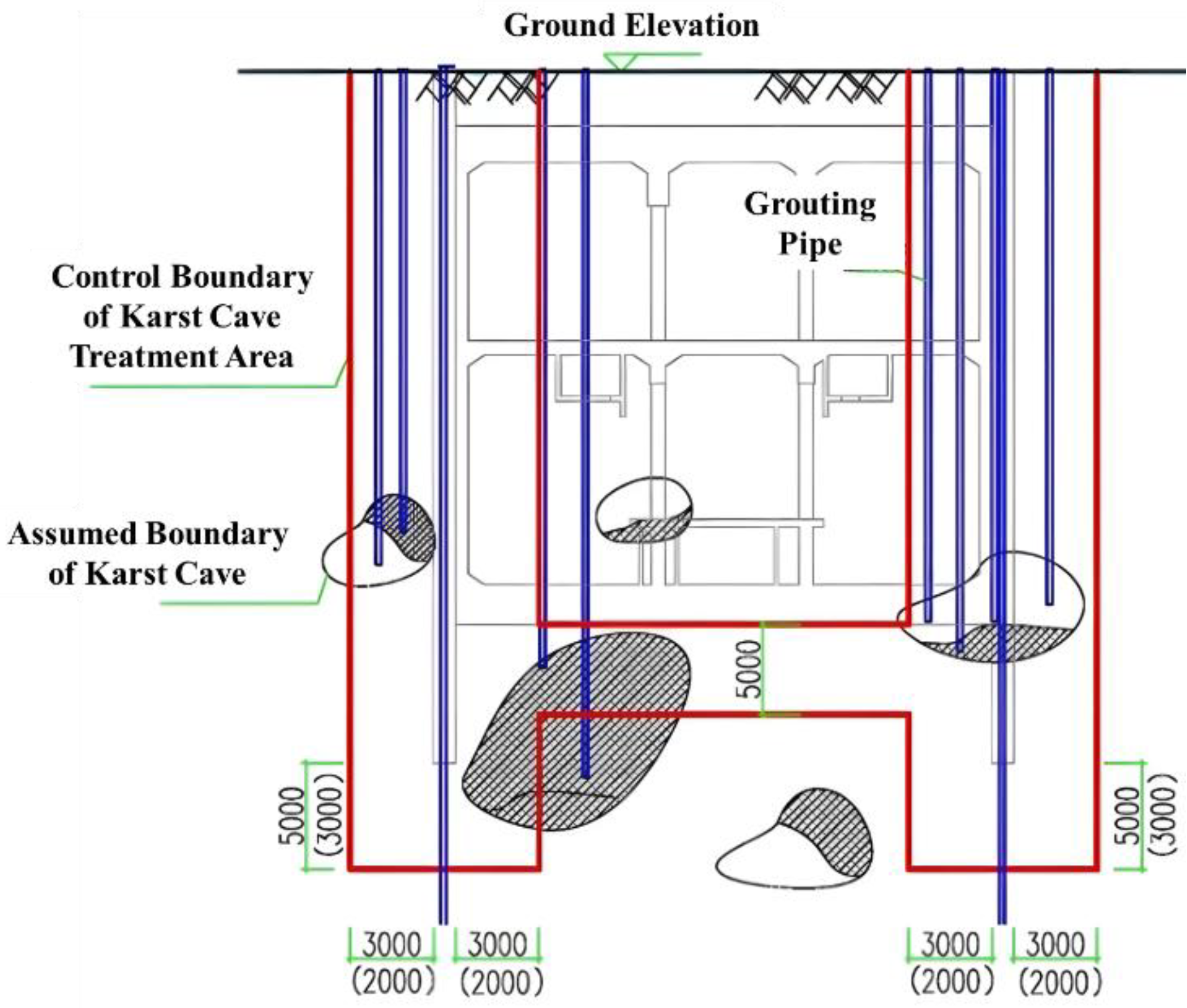
The karst treatment scheme in this study defines the treatment scope for diaphragm walls and foundation base as follows:
- ♦
Diaphragm wall treatment: 3 m inside and outside the wall and 5 m below the wall base.
- ♦
Foundation base treatment: 5 m below the base (
Figure 1, red line indicates the treatment boundary).
- ♦
During the construction of diaphragm walls and foundation bases, the “one-trench two-drilling” method (advanced drilling and edge-probing drilling) was adopted. Key principles include the following:
- ♦
Advanced drilling depth: Extending 5 m below the wall base.
- ♦
Dual functionality: Both advanced and edge-probing drill holes serve as grouting holes and venting holes.
- ♦
Adaptable operational execution: Grouting and drilling sequences follow total-quantity control principles and allow real-time adjustments.
Figure 1.
Schematic diagram of diaphragm wall and foundation base treatment scope in karst area. Red lines denote the treatment area.
Figure 1.
Schematic diagram of diaphragm wall and foundation base treatment scope in karst area. Red lines denote the treatment area.
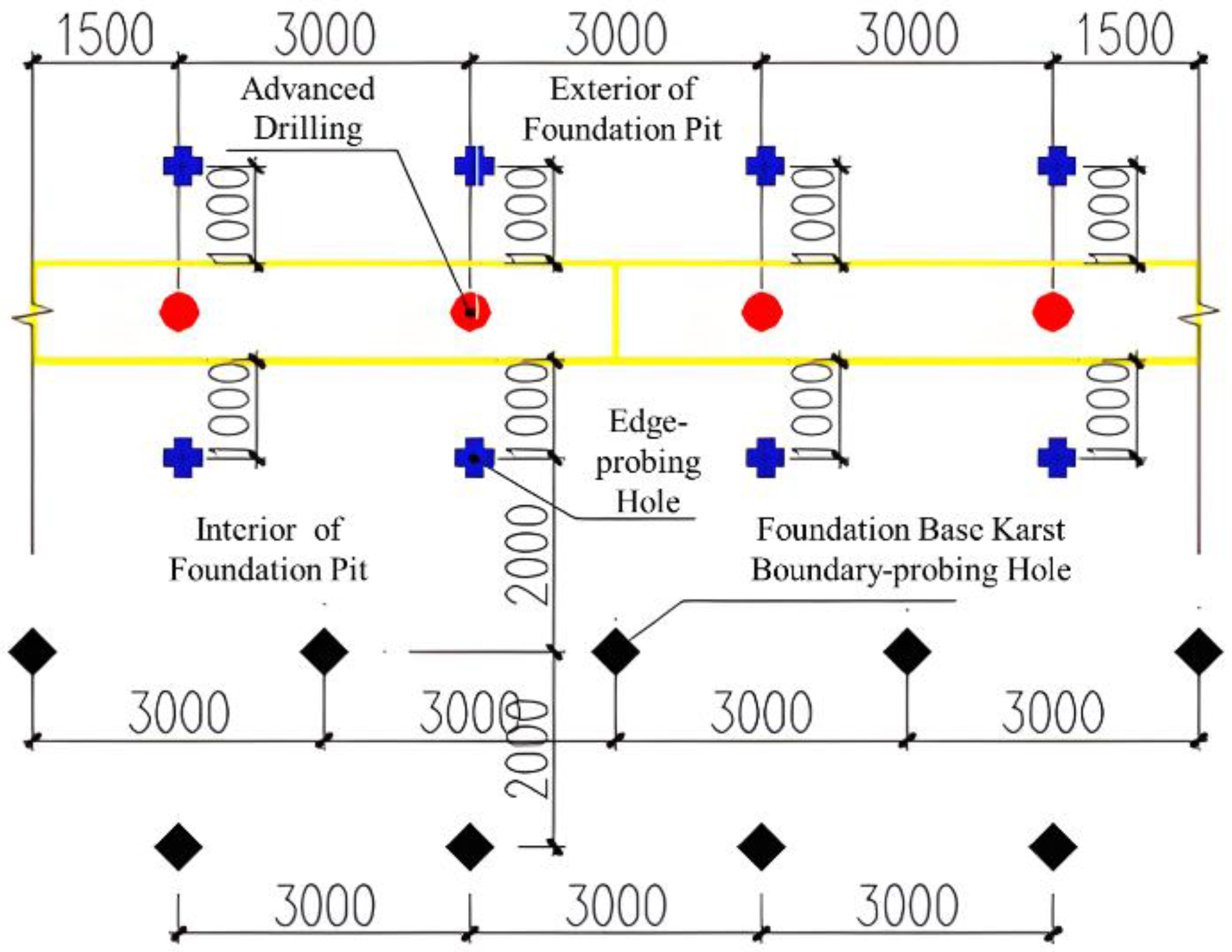
Drilling Specifications:
Temporary vertical piles and uplift piles: 1 advanced drilling hole per pile.
Bearing piles:
Pile diameter ≤ 1.5 m: 3 advanced drilling holes.
Pile diameter 1.8 m: 4 advanced drilling holes (compliant with provincial standards).
Depth Requirements for Advanced Drilling:
End-bearing piles (for station-supporting bearing piles and subway foundation pit temporary vertical piles): H ≥ 3 d (where H is the depth below the pile tip, and d is the pile diameter) and H ≥ 5 m.
Friction-end-bearing piles (for station foundation pit temporary vertical piles):
H ≥ 2.5 d and H ≥ 4 m.
Pure friction piles (all uplift piles):
H ≥ 1.5 d and H ≥ 2 m.
The layout of advanced and edge-probing drill holes is illustrated in
Figure 2 and
Figure 3.
Anchor Cable Karst Treatment Scope:
Horizontal range: 3 m on both sides of the anchor cable area and 5 m beyond the anchor segment end.
Vertical depth: 5 m below the anchor cable, determined by edge-probing drilling at the actual anchor depth.
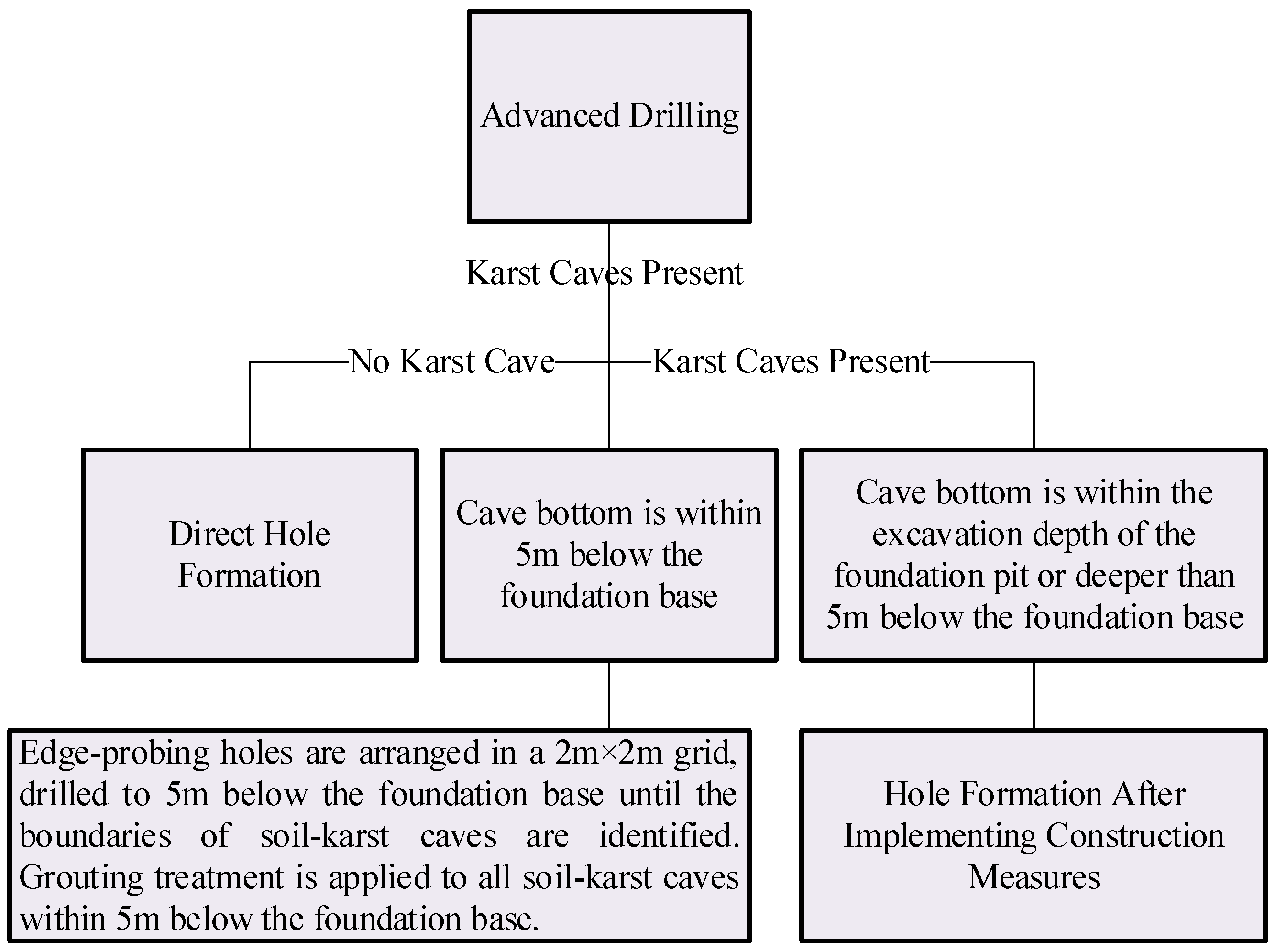
Additionally, the following depth extension principles shall be followed when engineering piles encounter karst caves:
For diaphragm walls: If a karst cave is encountered within the embedment depth range of the diaphragm wall, the wall shall penetrate the cave and extend into intact moderately to slightly weathered rock by at least 1 m while ensuring the final trench depth meets the design requirements.
For engineering piles (including vertical piles, uplift piles, and bearing piles): If a karst cave exists within the depth H below the pile tip, the pile shall penetrate the cave and extend into intact moderately to slightly weathered rock by 1 m. Furthermore, the rock stratum within the H-meter depth below the pile tip must extend into intact moderately to slightly weathered rock.
For uplift piles: If a karst cave is present along the pile shaft, the uplift pile shall be lengthened to ensure the cumulative embedded depth into intact rock is not less than the designed pile length.
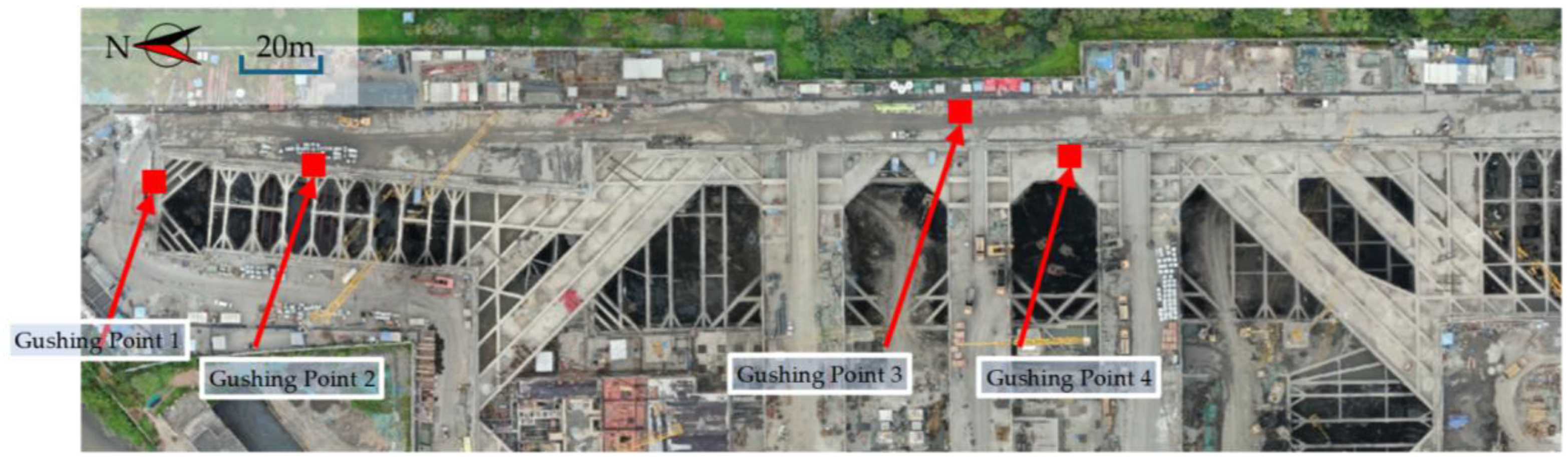
4. Emergency Treatment Scheme for Base Gushing Water
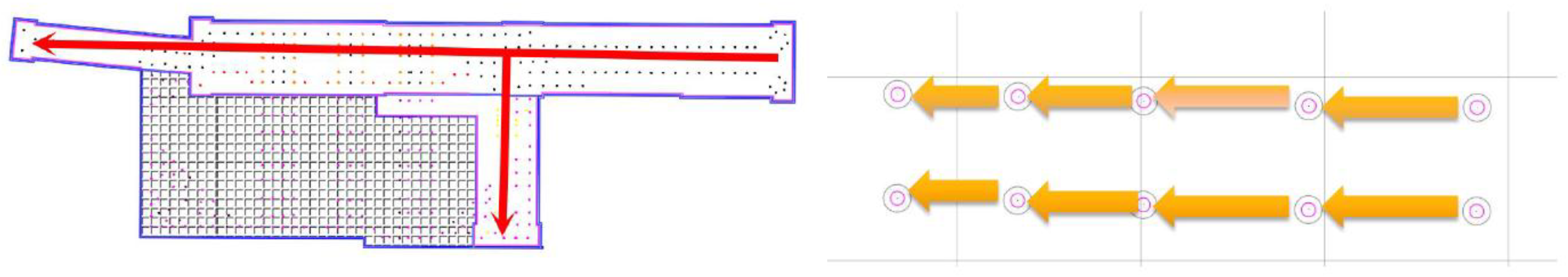
During the excavation of Section 1 at Tangxi Station, approximately four water inflow points emerged within the 35 m deep subway foundation pit (Lines 12/24). The locations of these points are illustrated in
Figure 4, and the on-site gushing conditions are shown in
Figure 5. The specific scenarios are as follows:
Gushing Point 1: Sudden water inflow occurred at the base when excavation reached 6 m above the foundation base.
Gushing Point 2: Sudden water inflow occurred at 8 m above the foundation base.
Gushing Point 3: Sudden water inflow occurred at 10 m above the foundation base, with a flow rate of approximately 20 m3/h.
Gushing Point 4: Water and sand gushing occurred near the diaphragm wall during base cleaning after reaching the foundation base, with a flow rate of 20 m3/h.
The emergency treatment scheme comprises four key steps:
Immediate sealing: Use cofferdams combined with concrete counter-pressure pouring to block the gushing points.
Cross-hole CT scanning: Conduct geological profiling outside the diaphragm wall to delineate karst cave boundaries.
Geological verification: Perform detailed drilling at identified karst cave locations to guide grouting operations.
Grouting treatment: Inject dual-fluid grout (cement slurry and sodium silicate), polyurethane, or mortar into the karst caves.
5. Key Technologies for Structural Fissure Seepage Remediation
5.1. Seepage Conditions in Base Slabs, Sidewalls, and Roofs
The zoning of the foundation pit in Section 1 is shown in
Figure 6. Reinforced concrete columns (vertical piles) are connected to the base slab through pre-reserved post-casting openings, which exhibited seepage. During structural construction, pre-embedded sleeves and reinforcement bars were installed for future connections, along with waterstop steel plates. The openings measure 2.7 m × 2.7 m, totaling 560 across all zones. The number of openings and base slab elevations for each zone are listed in
Table 2. Additionally, 496 seepage points were identified in the sidewalls and roof. This section analyzes the causes and remediation strategies for these seepage issues.
5.2. Analysis of Seepage Causes
Field investigations identified five primary causes of seepage:
Base slab opening leakage: Caused by untreated karst caves beneath the base, allowing water to seep through gaps between vertical piles and bedrock.
Sidewall leakage:
Thick sidewalls (1200/1000/800 mm from bottom to top) and the 450 m long subway structure led to significant thermal fissures during concrete curing.
Construction difficulties due to dense supports and the sidewalls’ location below waist beams introduced potential defects.
Thermal stress and deformation induced by cement hydration heat.
Internal and external constraint effects (e.g., uneven structural restraints).
Ambient temperature fluctuations.
5.3. Overall Scheme for Base Slab Opening Sealing
The sealing strategy is tailored to the seepage severity. Construction progresses in two routes:
Route 1: North to south, aligned with vertical pile removal.
Route 2: West to east along the Foshan Metro Line 8 (Fo’ba Line).
Adjacent openings on the same route are sealed with a minimum 7-day interval to mitigate hydraulic pressure buildup. The workflow is illustrated in
Figure 7 (Right indicates north).
5.4. Sealing Solutions for Non-Leaking, Minor, and Major Seepage Openings
- 1.
Case 1: No or Minor Seepage
Water collection pit: Excavate a 300 mm deep pit outside the pile head for drainage, ensuring dry conditions for rebar installation.
Grouting pipe setup: Install DN50 grouting pipes (temporarily sealed at the bottom with tape/check valves, extending 15 cm above the slab).
Concrete pouring: Cast 800 mm thick concrete up to the waterstop steel plate. After 7-day curing, seal the opening if no leakage is observed.
Grouting pipe reservation: Alternate spans are reserved with grouting pipes to prevent post-sealing leakage (
Figure 8a).
- 2.
Case 2: Major Seepage
Diversion and sealing: Install plum-blossom patterned perforated pipes to divert water flow, followed by staged grouting (
Figure 8b).
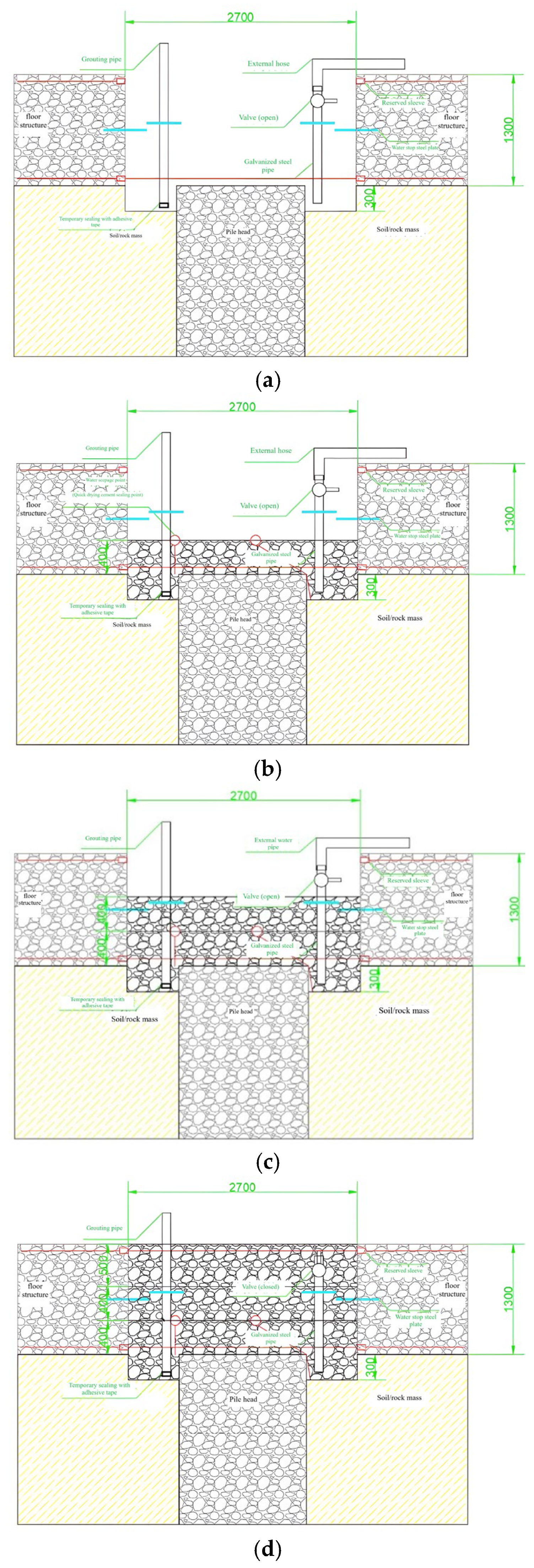
For Major Seepage in Base Slab Openings, the following prioritized construction scheme is adopted:
Water collection and drainage:
Excavate a 300 mm deep pit outside the pile head as a sump for water collection and pumping, ensuring dry conditions for rebar installation.
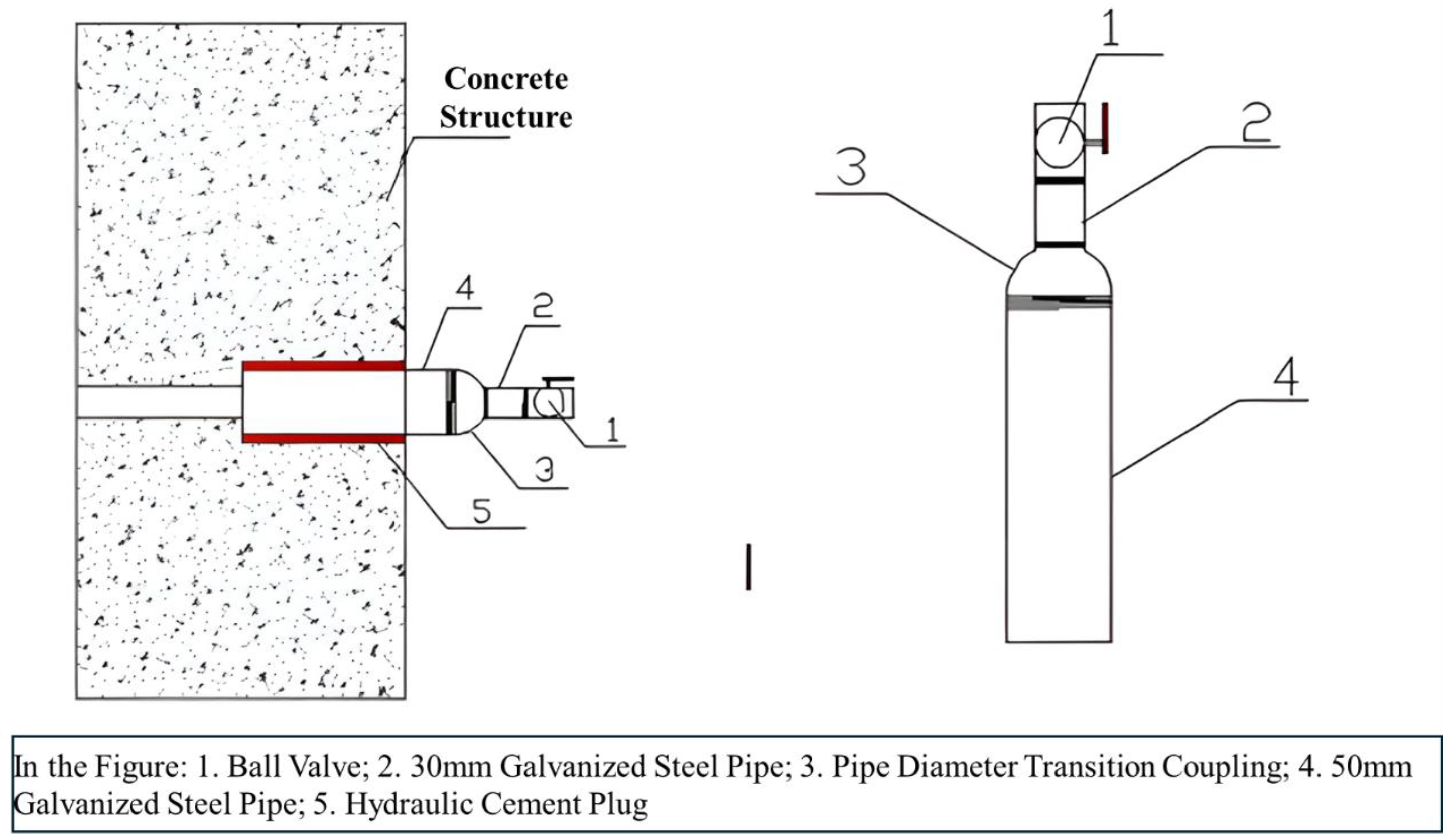
Embed a DN50 galvanized steel pipe with an external waterstop ring into the sump after installing rebar. The pipe bottom is temporarily sealed with tape or a check valve for future grouting.
Install another DN50 galvanized steel pipe on the opposite side, equipped with a waterstop ring and valve, connected to a flexible hose for drainage (
Figure 9a).
First-stage concrete pouring:
Pour a 400 mm thick concrete layer after base cleaning and rebar installation.
Temporary seal significant seepage points with hydraulic cement (e.g., “waterplug”), allowing water to drain through the diversion pipe (
Figure 9b).
Second-stage concrete pouring:
Pour a second 400 mm thick layer up to the waterstop steel plate and below the valve.
Begin curing after successful drainage (
Figure 9c).
Final-stage sealing:
Close the valve after 7-day strength development and pour the final concrete layer (
Figure 9d).
5.5. Systematic Grouting Treatment Scheme for Visible Water Leakage
General Principles:
- 1.
Leakage control strategy: “Drain before sealing”—transform large-area leakage into localized points for centralized sealing.
- 2.
Treatment sequence: Address major leaks first, then minor leaks; treat from low to high elevations, starting with the base slab, followed by walls, and finally the roof.
- 3.
Structural reinforcement: Conduct strength tests for fissures in concrete structures; reinforce if necessary before fissure sealing.
- 4.
Construction joints: Apply cement grout combined with polymer-modified epoxy resin waterproof mortar.
- 5.
Surface leakage: Reinforce structurally compromised areas and apply waterproofing; non-critical areas receive direct waterproofing.
- 6.
Point leakage: Apply targeted waterproof sealing.
- 7.
Prohibition: Polyurethane is strictly prohibited for leakage treatment.
Grout Selection Criteria:
- 1.
Single-fluid grout: Ordinary Portland cement PO42.5 with a Cement grout: w/c = 1.0 by mass (adjustable based on field conditions).
- 2.
Chemical grout: Low-viscosity epoxy resin grout meeting JC/T 1041—2007 (Grade II), with an epoxy resin: base/hardener = 3:1 (volumetric).
- 3.
Ultrafine cement grout: High-performance micro-cement with a cement/water ratio of 1:1 (adjustable as needed).
Grout Selection Rationale:
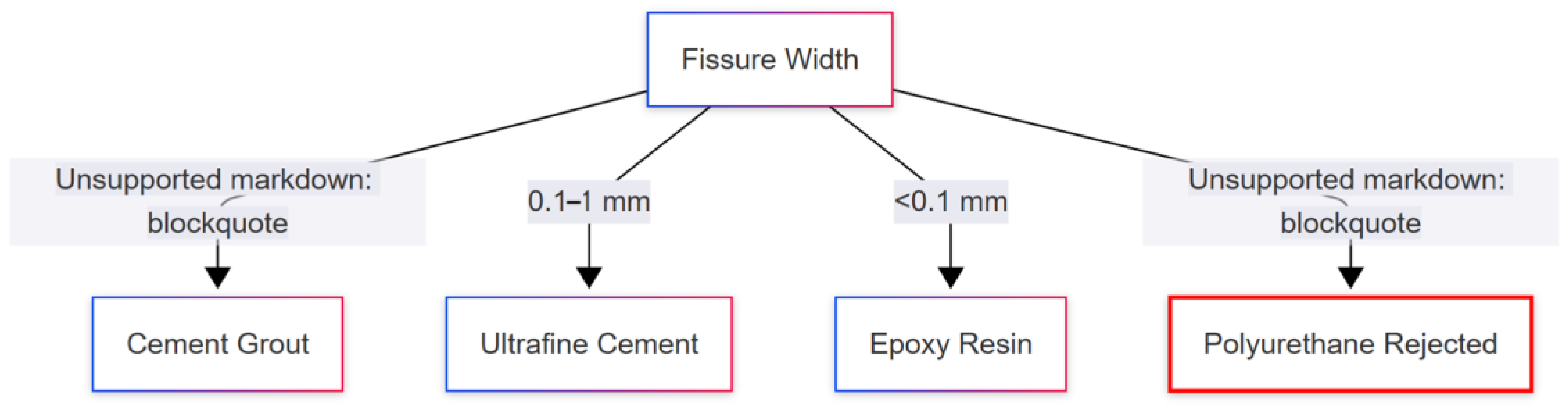
Material selection is optimized for fissure-scale hydrogeological conditions (as shown in
Figure 10):
- 1.
Cement grout: >1 mm macro-fissures
- ♦
Cost efficiency: CNY 580/ton vs. epoxy CNY 12,000/ton;
- ♦
Viscosity: 250–450 mPa·s (adequate for macro-penetration).
- 2.
Ultrafine cement: 0.1–1 mm meso-fissures
- ♦
Particle size: D95 = 8 μm (vs. standard cement D95 = 45 μm);
- ♦
CT-verified filling efficiency: 92%.
- 3.
Epoxy resin: <0.1 mm micro-fissures
- ♦
Low viscosity: 220 mPa·s (25 °C);
- ♦
Tensile strength: 35 MPa.
- 4.
Polyurethane rejection:
- ♦
Alkaline degradation: 12%/year in pH > 10 concrete;
- ♦
Five-year strength retention: 62% (vs. epoxy 92%).
- ♦
VOC emissions: >200 ppm (exceeds GB-50325) [
36].
Base slab grouting:
- 1.
Target pre-embedded grouting pipes at openings and construction joints.
- 2.
Pressure management protocol:
- ♦
Initial: 0.2–0.3 MPa (gauge);
- ♦
Final: ≤0.4 MPa (gauge).
- ♦
Termination criteria:
- (a)
Chinese standard GB 50446-2017 [
37] for fracture grouting in karst rocks (0.1–0.5 MPa safety range);
- (b)
Site-specific tests showing optimal permeability reduction (to 1.1 × 10⁻⁹ m/s) at 0.3 MPa for 0.1–1 mm fissures.
- 3.
Monitor pressure and flow rate; terminate grouting when pressure stabilizes at the final value for 30 min or grout overflows.
Sidewall grouting:
- 1.
Prioritize construction joints.
- 2.
Drill holes:
- ♦
Horizontal spacing: 15–20 m;
- ♦
Vertical arrangement: staggered positions (within 1/3 wall height).
- 3.
Maintain final pressure at 0.3 MPa.
- 4.
Ensure grout pipes are perpendicular to the structural surface (
Figure 11).
5.6. Epoxy Resin Treatment Scheme in the Absence of Visible Water
When no visible water is present, the epoxy resin treatment scheme proceeds as follows:
- 1.
Fissure Cleaning and Marking
Visible fissures: Directly mark the fissures with colored pens.
Damp surfaces: Remove accumulated water or dry the surface using an alcohol blowtorch (40–60 °C) before marking.
- 2.
Drilling Arrangement
Hole spacing: Determined by fissures width:
- ♦
A total 0.4–0.5 mm fissure width: holes spaced at ~0.4 m intervals.
- ♦
A total 0.3–0.4 mm fissure width: holes spaced at ~0.3 m intervals.
- ♦
A <0.3 mm fissure width: holes spaced at ~0.2 m intervals.
Layout: Holes are drilled in a plum-blossom pattern along both sides of the fissure, with a general spacing of 20–30 cm.
Drilling angle: Adjustable between 45 and 75° relative to the fissure plane, ensuring intersection with the fissure. Invalid holes occur if the drill fails to intersect the fissure.
- 3.
Waterstop Needle Installation
Pre-installation: Clean drill holes thoroughly with brushes to remove debris.
Depth control:
Avoid shallow embedding: Prevents grout leakage and residue accumulation.
Needle tip position: Must not exceed the fissure depth to ensure grout injection into the fissure.
Tightening: Securely fasten waterstop needles to prevent leakage.
- 4.
Epoxy Resin Specification:
The low-viscosity epoxy resin (JC/T 1041—2007 [
38] Grade II) exhibited the following:
Glass transition temperature (Tg): 58 ± 3 °C (per DSC testing, ASTM E1356 [
39])
Viscosity–temperature relationship:
- ♦
5 °C: 350 ± 20 mPa·s;
- ♦
25 °C: 220 ± 10 mPa·s ← Field application temperature;
- ♦
40 °C: 110 ± 5 mPa·s.
This profile ensures penetration into >95% of micro-fissures (0.05–0.2 mm) at karst groundwater temperatures (18–22 °C), with viscosity < 250 mPa·s being optimal for karst microfracture infiltration.
- 5.
Grout Injection
Sequence: Inject epoxy resin from the bottom upward along the structural surface. Stop immediately if grout overflows from the fissure.
Procedures:
- ♦
Bypass adjacent holes when grout saturation occurs.
- ♦
Drill supplementary holes for extended fissures.
- ♦
Complete secondary grouting prior to resin gelation.
- 6.
Equipment Cleaning
Thoroughly clean grouting tools and machinery after use.
6. Comprehensive Evaluation of Treatment Technology Effectiveness
6.1. Definition and Measurement Methods of Key Indicators
To systematically evaluate the technical effectiveness, the following core indicators (
Table 3) are defined and measured.
6.2. Effectiveness Analysis of Karst Treatment Technology
- 1.
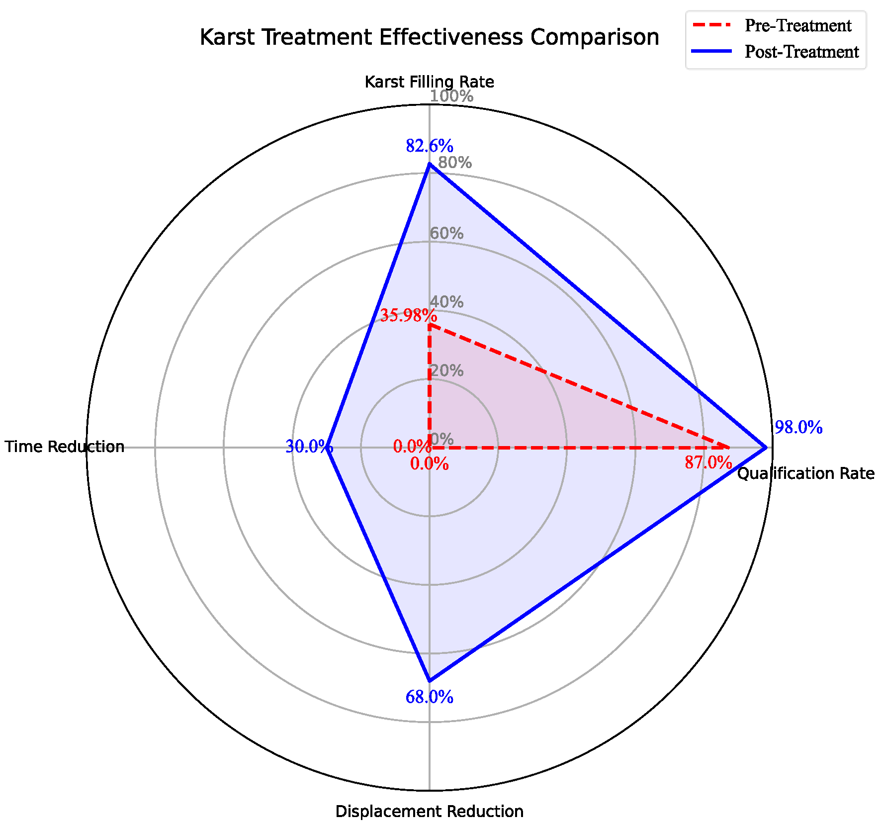
Significant Improvement in Karst Cave Filling Rate
Pre-treatment: The average filling rate was 35.98%, with fill materials predominantly composed of soft-flow clay (exhibiting poor stability).
Post-treatment: It increased to 82.6% (
Table 4), with fill materials transformed into cement–clay consolidated bodies, validated for compactness through borehole core sampling (
Figure 1). The comprehensive performance improvements across key parameters are visually synthesized in
Figure 12.
- 2.
Enhanced Foundation Pit Stability
Horizontal displacements at monitoring points decreased significantly:
D1: Reduced from 28.7 mm to 9.3 mm.
D2: Reduced from 25.4 mm to 8.1 mm (
Table 5).
This improvement primarily resulted from optimized karst cave filling and increased embedment depth of diaphragm walls.
- 3.
Improved Construction Efficiency
“One-trench two-drilling” method: Reduced redundant drilling operations, shortening single pile hole formation time by 30% compared to conventional methods.
Qualification rate of pile hole formation: Increased to 98%, significantly lowering rework rates and associated costs.
6.3. Verification of Emergency Water Inflow Control Effectiveness
- 1.
Timeliness of water inflow control
The maximum gushing point (20 m3/h) was reduced to 0.4 m3/h within 52 h using cofferdam sealing + dual-fluid grout injection.
Cross-hole CT scanning shortened karst cave localization time by 40%, enabling rapid grouting decisions.
- 2.
Validation of Grout Material Performance
Dual-fluid grout (Sodium silicate: cement/silicate = 1:0.8):
Initial setting time: 3–5 min.
The permeability coefficient decreased from 2.3 × 10
−4 cm/s to 1.1 × 10
−9 m/s (
Figure 2).
Polyurethane grout: Superior for sealing wide fissures (>5 mm) but with higher costs.
- 3.
Environmental Impact Control
Post-grouting maximum ground settlement: 4.2 mm (monitored by leveling instruments), with no secondary geological hazards.
6.4. Evaluation of Structural Seepage Remediation Effectiveness
- 1.
Base Slab Opening Repair Rate
A total of 560 openings were treated with layered casting + grouting pipe diversion, achieving a 96.4% success rate (540 sealed). The remaining 20 required secondary grouting due to micro-fissures.
- 2.
Sidewall Fissure Control
Epoxy resin grouting reduced fissure recurrence to 4.6% (23/496), primarily in thermal stress zones.
Grouted specimens achieved 35.2 MPa ± 1.8 compressive strength at 28 days, exceeding the original concrete strength (28 MPa) (
Table 6).
- 3.
Comparative Grout Performance
The technical–economic rationale for grout selection is validated by long-term performance data. Comparison results are shown in
Table 7.
- 4.
Economic Benefits
Reduced rework concrete removal: 1200 m3.
Cost savings: CNY 12 million.
Schedule shortened: 45 days.
6.5. Comprehensive Technical Advantages and Limitations
- 1.
Advantages
Multi-technology synergy: Combines sealing (water control), grouting (anti-seepage), and drainage (water level reduction) to address complex issues.
Dynamic adaptability: Real-time monitoring data optimizes grouting parameters (pressure: 0.3–0.4 MPa; grout ratios: 1:1 to 1:0.8), accommodating irregular karst distribution.
Environmental compatibility: No significant settlement or pollution, aligning with green construction principles.
- 2.
Limitations
Micro-fissure repair boundary: Mercury intrusion porosimetry (ASTM D4404 [
40]) of epoxy-grouted cores quantified the filling efficiency threshold:
>0.2 mm fissures: >98% filling (primary contributor to the 96.4% repair rate);
0.1–0.2 mm fissures: 85 ± 5% filling;
<0.1 mm fissures: <40% filling (accounting for 68.6% of residual permeability).
This delineates the 96.4% repair rate as effective primarily for macro-fissures (>0.2 mm), with efficiency declining exponentially below 0.1 mm.
Long-term durability uncertainty: Anti-aging performance of epoxy resin grout requires > 10 years of monitoring.


