Abstract
When deep-buried tunnels are excavated using the drill-and-blast method, the surrounding rock is subjected to combined cyclic blasting loads and excavation-induced stress unloading. Understanding the distribution characteristics of rock damage zones under these conditions is crucial for the design and safety of building-integrated underground structures. This study investigates the relationship between surrounding rock damage and in situ stress conditions through numerical simulation methods. A constitutive model suitable for simulating rock mass damage was developed and implemented in the LS-DYNA (version R12) code via a user-defined material model, with parameters determined using the Hoek–Brown failure criterion. A finite element model was established to analyze surrounding rock damage under cyclic blasting loads, and the model was validated using field data. Simulations were then carried out to explore the evolution of the damage zone under various stress conditions. The results show that with increasing hydrostatic pressure, the extent of the damage zone first decreases and then increases, with blasting-induced damage dominating under lower pressure and unloading-induced shear failure prevailing at higher pressure. When the hydrostatic pressure is less than 20 MPa, the surrounding rock stabilizes at a distance greater than 12.6 m from the tunnel face, whereas at hydrostatic pressures of 30 MPa and 40 MPa, this distance increases to 29.4 m. When the lateral pressure coefficient is low, tensile failure occurs mainly at the vault and floor, while shear failure dominates at the arch waist. As the lateral pressure coefficient increases, the failure mode at the vault shifts from tensile to shear. Additionally, when the horizontal stress perpendicular to the tunnel axis (σH) is less than the vertical stress (σv), variations in the axial horizontal stress (σh) have a significant effect on shear failure. Conversely, when σH exceeds σv, changes in σh have little impact on the extent of rock damage.
1. Introduction
With the rapid development of urban infrastructure and the increasing demand for land resources, the integration of underground space into building systems has become an important direction in sustainable urban development. In this context, the construction of deep-buried tunnels for building-integrated underground structures has seen a significant rise. The drill-and-blast method remains widely employed among various excavation techniques due to its adaptability to complex geological conditions. However, in high in situ stress environments, tunnel excavation often induces significant excavation damage zones (EDZs) in the surrounding rock, which can severely compromise the mechanical integrity and long-term stability of underground structures. An in-depth understanding of tunnel rock damage mechanisms is crucial for enhancing the long-term performance of underground structures, reducing maintenance costs and environmental risks, and supporting global efforts to promote green infrastructure construction and resource efficiency. Studies have shown that during drill-and-blast excavation, the combined action of high-frequency dynamic loads from blasting and static stress unloading leads to varying degrees of fracturing and cumulative damage in the surrounding rock [1].
Extensive field monitoring has revealed the strong influence of drill-and-blast excavation on the characteristics and spatial distribution of the EDZ. Techniques such as seismic velocity testing, scanning electron microscopy (SEM), acoustic emission analysis, and borehole imaging have been commonly used to evaluate damage. For instance, Hong et al. [1] employed ultrasonic reflection testing and found that EDZs at the vault and sidewalls of deep tunnels were significantly larger than at the arch shoulders, with depths ranging from 0.36 to 1.72 m depending on burial depth. Li et al. [2] utilized in situ sonic velocity measurements and the modified Hoek–Brown failure criterion to assess strength reduction, finding compressive and tensile strength reductions of over 70% and 90%, respectively. Further studies confirmed that drill-and-blast excavation causes irreversible cumulative damage with increasing blast cycles [3,4]. Martino and Chandler [5] reported that even under low-energy excavation, high-stress environments can lead to a differentiated EDZ comprising a severely damaged inner zone caused by blasting shock waves and a moderately damaged outer zone influenced by stress redistribution. Yang et al. [6] reached similar conclusions using numerical simulation methods. Case studies, such as those conducted at the Jinping II Hydropower Station, demonstrated that EDZ depths in TBM-excavated tunnels were around 3.0 m, while drill-and-blast sections exhibited EDZs of approximately 4.2 m due to more intense dynamic and static effects [7]. Similar observations were made in high-speed railway tunnel monitoring using extensometers and ground-penetrating radar [5,8]. Overall, these studies consistently indicate that the coupling of blasting loads and static stress release during excavation accelerates rock damage and significantly enlarges the EDZ [3,9]. It is estimated that only 20–40% of the energy from blasting contributes to direct rock breakage, while the remaining energy propagates into the surrounding rock in the form of elastic waves and plastic deformation, leading to strain concentration and cumulative degradation [4].
With advancements in computational tools, numerical simulation has become a key approach for investigating rock damage mechanisms during blasting. Various constitutive models have been developed to describe the damage evolution of rock materials. Since the introduction of the damage variable D in the GK model by Kipp and Grady [10,11], numerous dynamic damage models have emerged, including the TCK model [12], the KUS model [13], and the THRONE model [14]. Additionally, models based on statistical damage theory and fractal theory have been proposed to capture the complex failure behavior of rocks under dynamic loading [7,15,16,17]. Several dynamic damage models were originally developed for concrete—such as the Riedel–Hiermaier–Thoma (RHT) model [2], the Johnson–Holmquist (JH) model [18], and the Holmquist–Johnson–Cook (HJC) model [19]—have also been widely applied in rock blasting simulations. For example, Cui et al. [3] utilized the JH-2 model in ABAQUS (v2022) to simulate progressive damage from cyclic blasting and analyzed acoustic wave velocity attenuation to quantify damage. Ji et al. [8] used LS-DYNA to simulate both single and multiple full-face blasting scenarios, validating the model’s predictive accuracy for EDZ extent and peak particle velocity (PPV). Li et al. [2] estimated the Geological Strength Index (GSI) and disturbance factor from field P-wave velocity data, used the modified Hoek–Brown criterion to calibrate RHT parameters, and achieved close agreement between simulated and measured EDZ depths. Yilmaz and Unlu [20] examined the influence of the loading rate and anisotropic stress using FLAC3D (v.2.1), while Wang and Konietzky [21] applied a FEM–DEM coupled approach to investigate fracture evolution under in situ stress. Li et al. [22] found that as the ratio of horizontal-to-vertical in situ stresses increases, the dynamic effects on the tunnel-surrounding rock become significantly more intense, characterized by more cracks, larger failure zones, and greater kinetic energy release. Zou and Ma [23,24] found that plastic zones develop more extensively along the direction of minimum principal stress, reaching depths of up to 21.2 m without support, compared with just 7.9 m in the direction of maximum principal stress. This indicates that in situ stress governs both the depth and orientation of shear failure. Xu et al. [25,26] systematically investigated the influence of geostress on the reinforcement effectiveness of tunnel-surrounding rock. Their results show that when geostress exceeds 8 MPa, the reinforcement effect deteriorates significantly. Furthermore, when geostress is below 16 MPa, ignoring stress conditions may cause the grouting area to be overestimated by up to 91%. Ma and An [27] studied the effects of pre-existing joints and stress conditions, finding that blast-induced fractures tend to align with the principal stress direction. These studies demonstrate the value of numerical modeling for understanding and predicting damage evolution in drill-and-blast tunnel excavation.
Despite the progress made, current research still faces limitations. Most previous simulations have focused on stress redistribution and transient unloading effects using two-dimensional models, which cannot fully capture the complexities of actual tunnel excavation. In recent years, more advanced three-dimensional simulations have been employed, but they still tend to overlook the effects of continuous unloading and cumulative damage from cyclic blasting. In this study, an improved HJC constitutive model based on the Hoek–Brown failure criterion is proposed and implemented in the dynamic finite element software LS-DYNA (version R12). Using a large-scale deep-buried tunnel for a building-integrated underground project in China as the engineering background, a multi-cycle excavation simulation is conducted through LS-DYNA’s restart capability. The evolution of surrounding rock damage under cyclic blasting is analyzed in detail, and the numerical results show strong agreement with field data. After validating the model, simulations under varying in situ stress conditions are performed to systematically investigate their influence on damage distribution. The results provide valuable insights for the design, assessment, and safety control of building-integrated underground structures involving deep-buried tunnel excavation.
2. Numerical Model
2.1. Blasting Load
During tunnel excavation using the drill-and-blast method, hundreds of blast holes typically exist on the tunnel face. Modeling each individual hole poses significant challenges for mesh generation and computational efficiency. Consequently, several simplified methods for estimating blasting loads have been proposed, which approximate the explosive pressure using semi-empirical formulas and detonation theory. The blasting pressure of the cutting holes is calculated using the following equation [8]:
where Pc denotes the equivalent boundary blasting pressure of the cutting holes; P0 is the detonation pressure of the blast hole; m is the multi-hole detonation influence coefficient; μ is the Poisson’s ratio of the rock mass; and the parameters rb, rc, and rf represent the blast hole radius, the radius of the crushed zone, and the radius of the fracture zone, respectively. The blasting pressure for other types of holes (such as breaking holes, smooth holes, and bottom holes) is calculated using the following equation [28]:
where Ps denotes the equivalent boundary blasting pressure of the other types of holes; S represents the spacing between adjacent blast holes; and db denotes the diameter of the blast hole. The pressure–time history of the detonation pressure in a blast hole is typically simplified as a bilinear function [29,30]:
where td denotes the total duration of blast hole pressure, typically ranging from 10−6 to 10−1 s. tr represents the pressure rise time, which can be calculated from the blast hole length L and the detonation velocity of the explosive VD as tr = L/VD [31]. Pm is the peak pressure in the blast hole, and it is calculated using the following equation:
where ρ0 is the density of the explosive and γ is the specific heat ratio of emulsion explosives, typically approximated as 3.0 [32]. K is the radial decoupling coefficient, defined as the ratio of the blast hole diameter to the explosive charge diameter. l is the axial decoupling coefficient, calculated as the ratio of the sum of the charging interval and the charge length to the charge length. n denotes the amplification factor of shock wave pressure acting on the blast hole wall.
The computational model used in this study is from Ji et al. [8]. Full-face millisecond delayed blasting is adopted for tunnel excavation, with an advance of 4.2 m per round. The blast hole layout is shown in Figure 1. Each full-face blast is divided into seven delay segments, initiated using non-electric millisecond delay detonators numbered from 1 to 13. It is assumed that all blast holes within the same delay segment detonate simultaneously, and the delay deviation of detonators is not considered. The cutting holes, breaking holes, and bottom holes are charged continuously from the bottom upward, while the smooth holes are charged with one explosive cartridge every 80 cm from the bottom of the hole. Using Equations (1)–(4), the equivalent blasting pressures for different types of blast holes are determined, as summarized in Table 1.
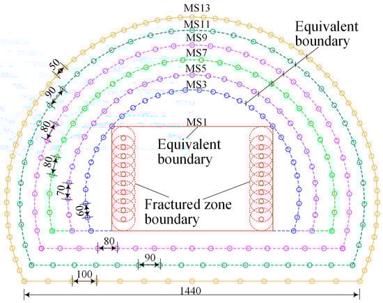
Figure 1.
Schematic diagram of the blast holes in the excavated tunnel cross-section (Units: cm) [8].

Table 1.
Equivalent blasting load.
2.2. Rock Mass
The mechanical parameters of the rock are primarily obtained from laboratory tests conducted on intact rock specimens. In this study, the granite reported in reference [8] is selected as the material; its mechanical properties are summarized in Table 2.
Table 2.
Mechanical parameters of rock specimens [8].
However, in practical rock engineering applications, the rock mass typically contains numerous discontinuities. As a result, using mechanical parameters derived from laboratory tests on rock specimens tends to overestimate the strength characteristics of the in situ rock mass. To address this, the Hoek–Brown failure criterion is employed to estimate rock mass parameters based on the mechanical properties of intact rock specimens obtained from the test tunnel [33]. The Hoek–Brown failure criterion establishes a relationship between the strength of intact rock and that of the rock mass, as follows [34]:
where σrc is the uniaxial compressive strength of the intact rock, and mb, s, and a are the three parameters of the Hoek–Brown failure criterion, which are calculated using the following three equations:
where mi is the intact rock constant, which is typically taken as 32 for granite. For undisturbed rock masses, the disturbance factor D = 0, and the Geological Strength Index (GSI) can be calculated using the following equation [2]:
where Vpm represents the wave velocity of the rock mass. According to Ji et al. [8], the wave velocity of intact rock is approximately 4.2 km/s. Although Table 2 does not explicitly provide the uniaxial compressive strength of the rock specimen, it can be estimated using the Mohr–Coulomb criterion as follows:
where c is the cohesion and ϕ is the friction angle. In the Hoek–Brown failure criterion, to reflect the overall strength of the rock mass, the “global rock mass strength” of the rock mass is defined as follows [34]:
Hoek et al. [34] proposed an equation for estimating the rock mass modulus of deformation (Em) using GSI and D:
The longitudinal wave velocity of the rock mass is associated with the shear modulus by the following equation:
where λ is the Lamé constant, G is the shear modulus, and ρ is the density of the rock mass. The Lamé constant can be calculated using the following equation:
where μ is the Poisson’s ratio. According to Equations (13) and (14), once the Poisson’s ratio is specified, the bulk and shear moduli of the rock mass can be derived from the longitudinal wave velocity. In this study, Poisson’s ratio of the rock mass is 0.20. The mechanical parameters of the rock mass based on the Hoek–Brown failure criterion are summarized in Table 3.
Table 3.
Values of undisturbed rock mass parameters.
2.3. Description of Rock Damage Model
LS-DYNA incorporates a variety of constitutive models capable of simulating the complex dynamic response of rock materials under blasting loads. Common rock constitutive models include the HJC model, the RHT model, and the JH series models, among others. Each of these models has its own strengths and is suited to different scenarios of rock failure simulation. However, since these models were originally developed for concrete materials, they exhibit certain limitations when applied to rock simulation. Therefore, this study proposes a modified HJC model to enhance the predictive capability for rock damage characteristics. In the modified model, when strain rate effects are neglected and no damage has occurred, the yield surface of the material is divided into two segments based on the magnitude of the normalized hydrostatic pressure p*:
where represents the normalized equivalent strength of the undamaged material; σeq is the effective stress strength; fc is the uniaxial compressive strength; and A, B, and N are parameters of the yield surface. denotes the normalized hydrostatic pressure and is the normalized hydrostatic tensile strength. When the material damage reaches a value of 1.0, the yield strength is calculated using the following equation:
where represents the normalized strength of the fully damaged material, σeq1 is the effective stress strength at full damage, and Bf and Nf are the parameters of the residual strength surface.
In the original HJC model, the strain rate effect is described using a logarithmic linear function based on the Cowper–Symonds model. However, previous studies have shown that the influence of strain rate is significantly greater in tension than in compression. Therefore, drawing on the strain rate enhancement factor approach used in the RHT model, this study incorporates both tensile and compressive strain rate effects:
where DIFc and DIFt represent the dynamic increase factors under compressive and tensile loading, respectively. Based on the work of Zhang and Zhao [35], Xie et al. [36] proposed using an exponential model to account for the dynamic enhancement effects as follows:
where denotes the strain rate. = 3.0 × 10⁻⁵ s−1 and = 3.0 × 10⁻⁶ s−1 are the reference strain rates under compressive and tensile loading, respectively. = 0.1 s−1 and = 30 s−1 represent the threshold strain rates at which tensile and compressive effects become significant. βc = 0.512, βt = 2.4, = 0.026, and = 0.007 are empirical coefficients [35]. In the modified HJC model, the damage calculation method remains unchanged. Damage accumulates based on equivalent plastic strain and plastic volumetric strain. The damage variable is expressed as follows:
where D is the damage variable; and are the increments of effective plastic strain and plastic volumetric strain, respectively. D1 and D2 are damage constants. EFmin is used to suppress the cracking caused by low-tensile stress waves. In summary, the equivalent yield stress of the rock is expressed as follows:
where σ* represents the normalized equivalent yield strength. In addition to reducing the deviatoric stress strength, damage also leads to the degradation of the shear modulus:
where GD is the shear modulus after damage, and ξ is the shear modulus reduction factor, which can be taken as 0.5 according to Equation (12).
In the proposed modified model, the parameters of the yield surface must be determined through calibration and fitting. By substituting D = 0 into Equations (2) and (3), the parameters of the Hoek–Brown failure criterion for the undamaged state are obtained. By setting σ2 = σ3 and substituting σ3 into Equation (5), σ1 can be derived. A series of σ1, σ2, and σ3 values is then used to fit the parameters A, B, and N. Similarly, by substituting D = 1 into Equations (6) and (7), the parameters of the Hoek–Brown failure criterion for the fully damaged state are determined. The residual strength parameters Bf and Nf are obtained through fitting. As shown in Figure 2a, the fitted strength curve demonstrates good agreement with the Hoek–Brown failure envelope.
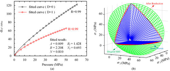
Figure 2.
Fitting results of the modified HJC model parameters: (a) fitting results of strength; (b) fitting results of yield surface.
By plotting the yield surface of the modified model together with that of the Hoek–Brown failure criterion in the principal stress space, as shown in Figure 2b, it can be observed that although the two yield surfaces exhibit good agreement along the compressive meridian after fitting, significant discrepancies remain in other regions. Therefore, a Lode angle function is introduced to reduce the strength along the shear and tensile meridians:
where is the Lode angle, and Q is a coefficient calculated using the following equation:
where Q0 and B0 are constants. Tests indicate that the yield surface of the modified model most closely matches that of the Hoek–Brown failure criterion when Q0 = 0.6 and B0 = 0.01. The modified yield surface is represented by the blue curve in Figure 2b.
The values of D1, D2, and EFmin are adopted from those reported in the reference [2]. The detailed material parameter values are presented in Table 4.
Table 4.
Modified HJC parameters of an undisturbed rock mass.
3. Model Validation
To verify the rationality of the modified HJC constitutive model parameters, a three-dimensional numerical model of tunnel blasting excavation was established using the LS-DYNA finite element software. Except for the right boundary, which is defined as a symmetry boundary, all the other boundaries are specified as non-reflecting. In LS-DYNA, non-reflecting boundaries are implemented using the * BOUNDARY_NON_REFLECTING Keyword. This boundary condition essentially functions as a viscous boundary, where the program computes an impedance matching function for all non-reflecting boundary segments based on an assumption of linear material behavior, effectively suppressing stress wave reflections [37]. Initial in situ stresses were applied to all elements, with σv = 0.60 MPa and σH = σh = 0.45 MPa [38]. A total of 14 excavation cycles were simulated, each with a length of 4.2 m. The rock mass corresponding to each detonator series was divided into separate geometric bodies, with equivalent blasting loads applied to their surfaces, as shown in Figure 3a. Excavation was initiated from the center of the model rather than from a boundary to avoid instability caused by deleting elements at the model edges. Because rock remained unexcavated behind the excavation face, the stress state near the excavation face differed from real conditions. To approximate the true stress state, elements located 8.4 m behind the first excavation cycle and within the excavation contour were removed after applying the initial stress field. After each excavation cycle, dynamic relaxation was conducted to dissipate kinetic energy and ensure the model remained in quasi-static equilibrium before the next cycle. Prior to each blast initiation, LS-DYNA’s small restart function was used to delete excavated elements and apply the blasting load to the excavation boundary. A delay interval of 20 ms was used for sequential blasting [8]. The mesh size in finite element models influences both stress wave propagation and computational accuracy. In this study, the wave velocity in intact rock is 4.2 km/s, while in damaged rock—where the modulus is reduced by half—the wave velocity drops to 2.1 km/s. The blast load duration is 5 ms, leading to a wavelength of 21 m in intact rock and 10.5 m in damaged rock. To ensure accurate stress wave propagation, the mesh size should be less than one-sixth of the wavelength [39,40,41]. This means the element size should not exceed 3.5 m in regions far from the tunnel and should be no more than 1.75 m near potential damage zones close to the tunnel. However, beyond stress wave propagation, computational accuracy is equally important. Tunnel excavation profiles consist of multiple element boundaries, and oversized elements may distort the geometric accuracy of the excavation. Additionally, since damage data are recorded at the element level, excessively large elements reduce the precision of damage assessment. Therefore, to balance computational accuracy with computational efficiency, we adopted a zoned mesh refinement strategy [42]. Specifically, fine meshes with a minimum element size of 0.15 m were applied near the tunnel, especially in regions where damage is expected to concentrate, while the mesh was gradually transitioned to a maximum element size of 2.3 m in zones far from the tunnel. To avoid numerical reflections caused by abrupt changes in element size, we implemented a multistage gradual transition in the mesh spacing, ensuring the stability of the simulation and fidelity of stress wave propagation. Based on model symmetry, a numerical model with dimensions of 70 × 35 × 84 m was constructed. The mesh included 526,812 nodes and 509,980 elements, as shown in Figure 3b.

Figure 3.
Tunnel excavation model: (a) symmetric half-model; (b) finite element mesh.
Although the model requires several minor restarts to simulate rock excavation and apply equivalent blast loading, these restarts do not modify the boundary conditions. As a result, the boundary stresses remain constant, allowing the model to simulate both blast-induced damage and progressive unloading damage caused by continuous tunnel face advancement.
The variation in model kinetic energy throughout the excavation process is shown in Figure 4a, with a peak value of approximately 40 MJ. The total physical time simulated is 3.5 s. The kinetic energy trend for a single excavation cycle is illustrated in Figure 4b, where the maximum energy occurs at the fifth-millisecond delay (MS9). After the application of blasting loads, kinetic energy gradually dissipates due to the presence of non-reflecting boundaries. However, in the later stage of the current excavation cycle, the energy dissipation through viscous boundaries alone becomes inefficient. Therefore, when the rate of energy decay significantly slows down, we introduce dynamic relaxation to accelerate the dissipation process. During the dynamic relaxation phase, the application of artificial damping causes the kinetic energy to rapidly decrease and approach zero, as shown in Figure 4b. When the distortion kinetic energy falls to one-thousandth of its peak value, the computation is considered to have converged, indicating that the model has reached a quasi-static equilibrium [43]. This final state is then used as the initial condition for the next excavation cycle.
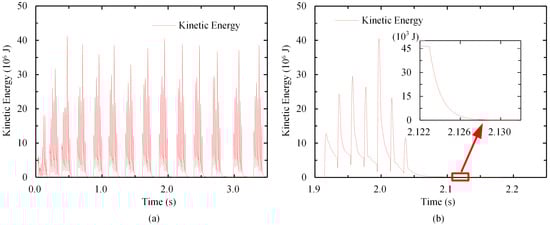
Figure 4.
Kinetic energy variation curves: (a) kinetic energy curve of the model during the entire excavation process; (b) kinetic energy curve of the model during a single excavation cycle.
The longitudinal section of the simulation results is shown in Figure 5. It can be observed that the extent of the damage in the first few excavation cycles differs significantly from that in the later cycles. This discrepancy is mainly due to the confining effect of the unexcavated section behind the tunnel face, which distorts the in situ stress condition during blasting. Similarly, the surrounding rock damage in the 14th excavation cycle differs from that in the middle sections, as the damage in the latter cycles has not fully evolved and will continue to develop as the tunnel face advances. In contrast, the damage states of the surrounding rock during the intermediate excavation cycles are relatively consistent, indicating that the influence of the front and rear constraints has largely dissipated. This allows for a more realistic representation of the actual damage characteristics of the surrounding rock during tunnel excavation.

Figure 5.
Distribution of surrounding rock damage on the longitudinal cross-section and position of the horizontal cross-section.
To evaluate the damage distribution of surrounding rock in the tunnel cross-section, three cross-sectional planes (Section 1, Section 2, and Section 3) were placed at the locations corresponding to the 7th to 9th excavation cycles, as shown in Figure 5. Since a single cross-section may not fully represent the damage characteristics, the damage cloud data over the length of one excavation cycle were averaged to obtain a more representative damage profile, as illustrated in Figure 6. The results show that the damage distribution across the three sections is largely consistent, with the minimum damage occurring at the arch waist and the maximum damage depth observed at the vault and floor. The damage distribution exhibits a distinct zonal pattern: a relatively wide zone of severe damage is observed near the excavation boundary, followed by a weakly damaged zone where the damage intensity gradually decreases to almost zero.
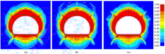
Figure 6.
Distribution of surrounding rock damage on the horizontal cross-section: (a) Section 1; (b) Section 2; (c) Section 3.
To verify the accuracy of the simulation results, a comparison was made with the field measurements conducted by Ji et al. [8]. In the field test, three acoustic testing holes (designated as S1, S2, and S3) were arranged near the tunnel arch foot at the excavation cross-section, as illustrated in Figure 7, for assessing the depth of rock damage. Each testing hole was 5 m long and had a diameter of 40 mm. The testing holes were inclined downward at an angle of 5° with respect to the horizontal plane.
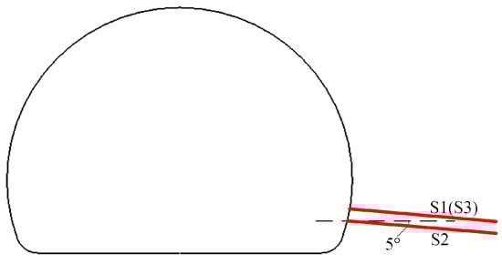
Figure 7.
Arrangement of acoustic wave testing holes.
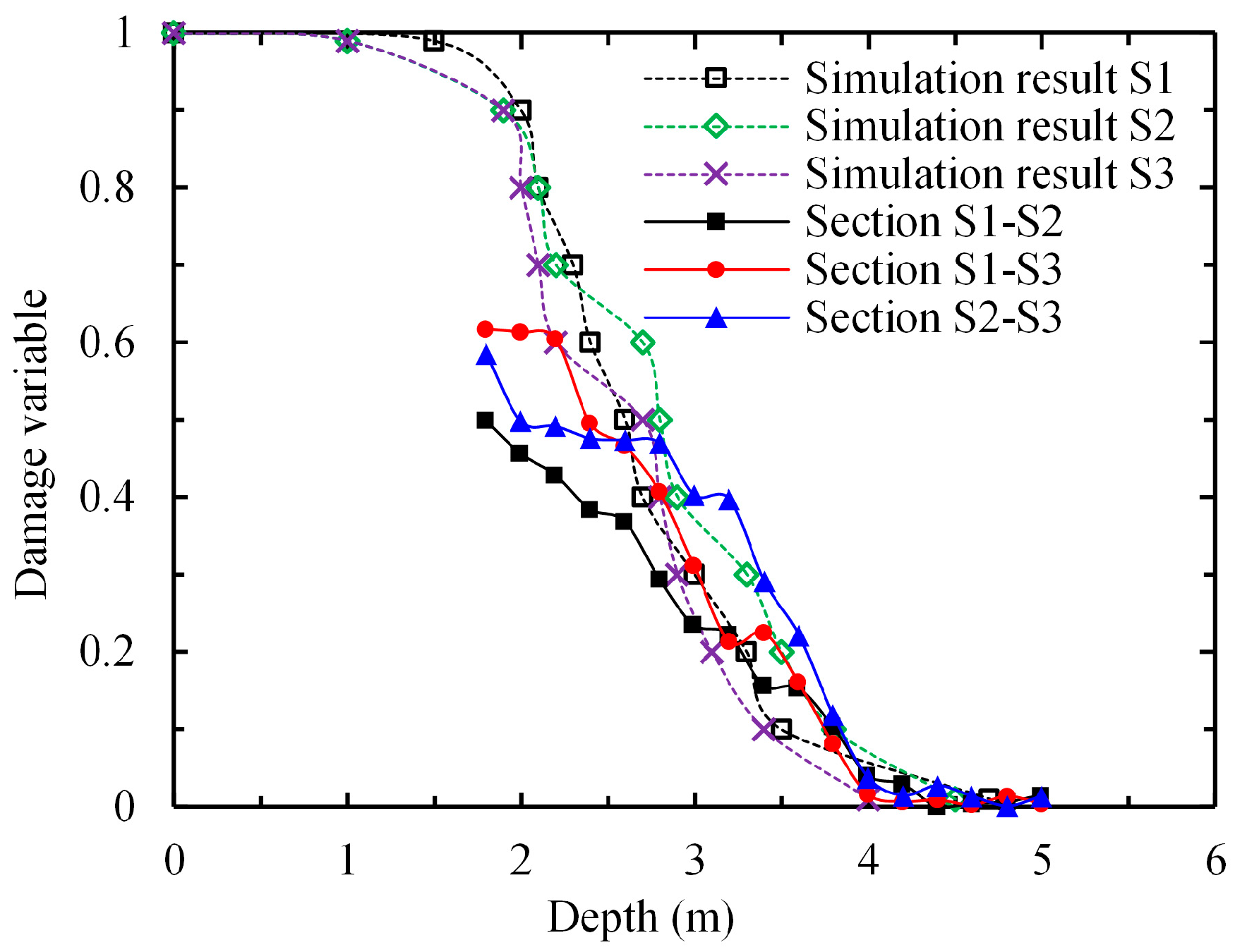
Figure 8 shows a comparison between the simulated damage of the surrounding rock above the arch waist and the acoustic wave detection results. The consistent trends in damage depth observed in both datasets indicate the reliability of the material model, loading assumptions, and finite element modeling approach adopted in this study.
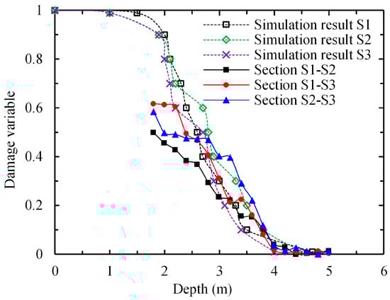
Figure 8.
Variation in damage variable D with depth.
4. Results
To investigate the characteristics of surrounding rock damage under various in situ stress conditions during drill-and-blast excavation, numerical simulations were conducted based on the previously validated model. The simulations were performed under different hydrostatic pressures and lateral pressure conditions. Apart from modifications to the initial stress state, all the other modeling parameters remained consistent with those used in the validation model.
4.1. Damage Distribution Under Different Hydrostatic Pressures
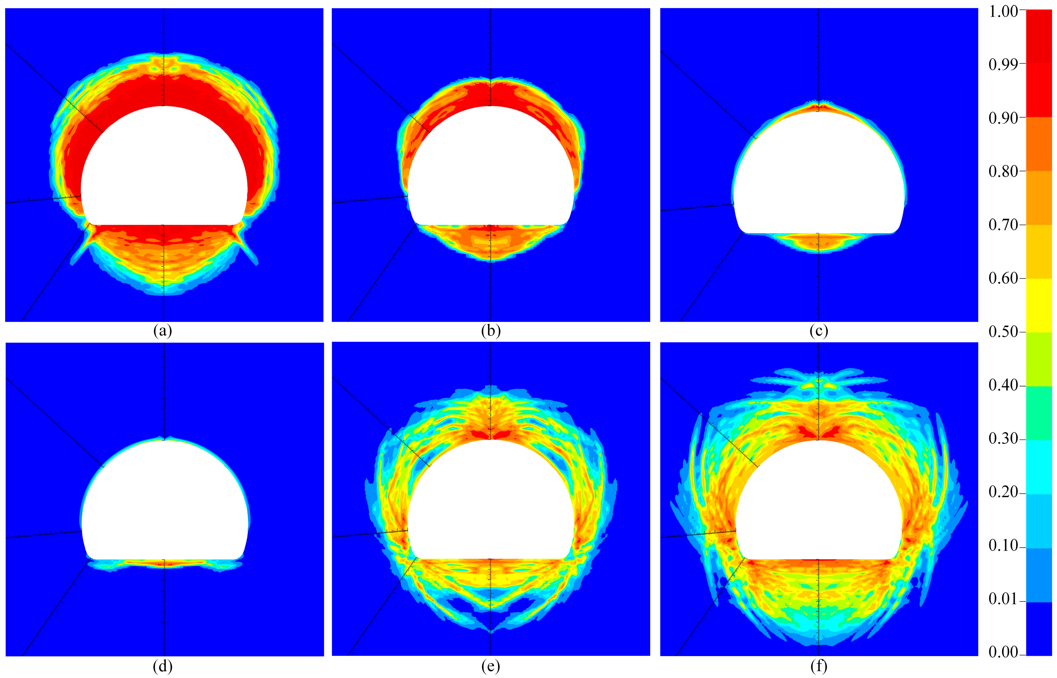
Figure 9 illustrates the damage distribution of tunnel-surrounding rock under hydrostatic pressures of 5 MPa, 10 MPa, 15 MPa, 20 MPa, 30 MPa, and 40 MPa, corresponding to Figure 9a–f. The blasting load remains constant across all the cases to isolate and highlight the influence of hydrostatic pressure variations on damage characteristics. The color contours in the figures represent the damage variable, ranging from 0 (undamaged) to 1 (fully damaged). Under low-stress conditions (Figure 9a,b), the surrounding rock exhibits extensive damage, particularly above the arch foot, where high damage values (close to 1) are concentrated, indicating that blasting is the dominant cause of failure due to the limited confinement. As the hydrostatic pressure increases to 15 MPa and 20 MPa (Figure 9c,d), the damage zone contracts significantly, owing to the hydrostatic pressure effect of rock, which increases tensile and compressive strength and thus suppresses damage propagation. With further increases in hydrostatic pressure to 30 MPa and 40 MPa (Figure 9e,f), the damage characteristics shift: direct blast-induced damage continues to decrease, while strong stress relief from excavation induces pronounced shear failures. Circumferential and radial shear bands emerge, forming damage strip structures oriented at specific angles, indicative of strong shear action near the tunnel face under high stress. This shift occurs because high initial stresses drop rapidly after excavation, reducing radial confinement and triggering shear-dominated failures. In summary, hydrostatic pressure significantly influences the damage pattern and mechanism: at low stress, tensile damage from blasting prevails; increased confinement strengthens the rock and reduces damage; and at high stress, excavation-induced unloading becomes dominant, leading to shear-governed damage distributions.
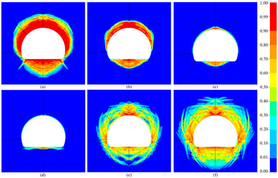
Figure 9.
Distribution of surrounding rock damage under different hydrostatic pressures: (a) pressure = 5 MPa; (b) pressure = 10 MPa; (c) pressure = 15 MPa; (d) pressure = 20 MPa; (e) pressure = 30 MPa; (f) pressure = 40 MPa.
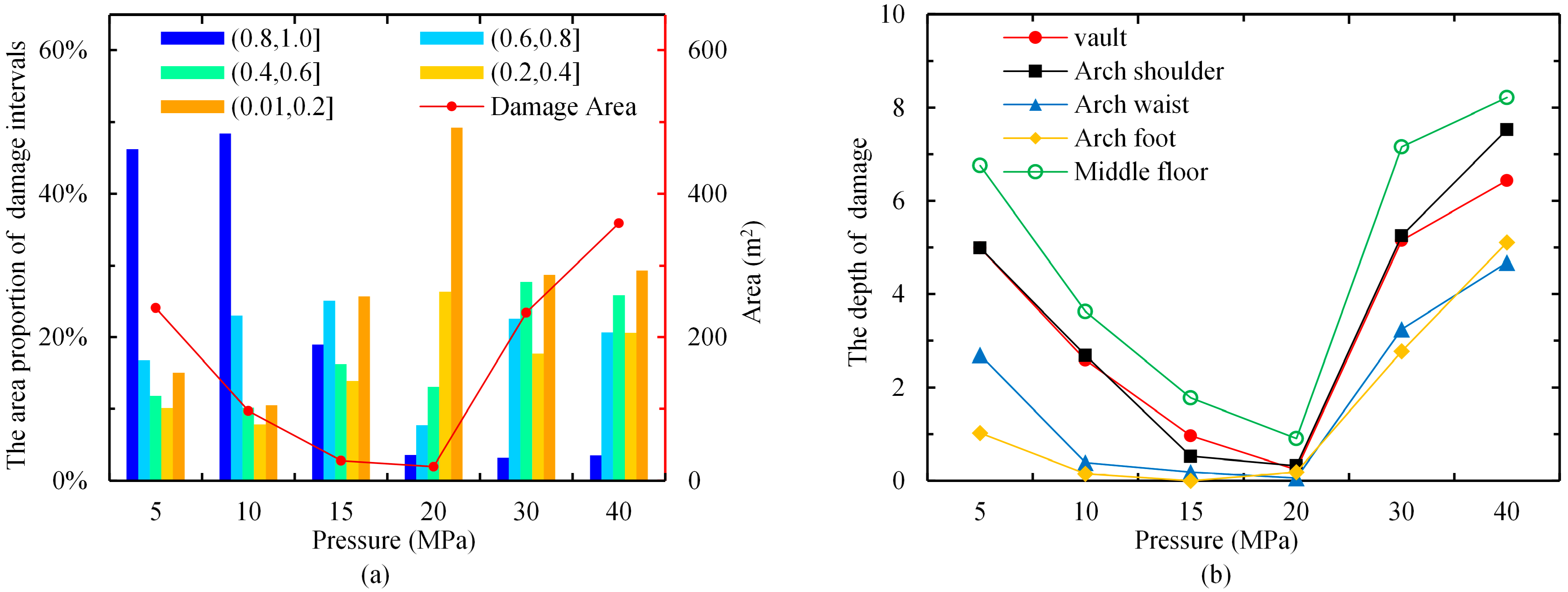
Figure 10 presents a statistical analysis of the damage characteristics of tunnel-surrounding rock under various hydrostatic pressure conditions after blasting excavation. Figure 10a shows the proportion of areas with different damage levels relative to the total damage area and its variation with hydrostatic pressure. Figure 10b illustrates the variation in damage depth at different positions around the tunnel as the hydrostatic pressure changes. As shown in Figure 10a, under low hydrostatic pressure conditions (5 MPa and 10 MPa), severely damaged zones (damage variable between 0.8 and 1.0) account for the largest portion of the total damage area. At 5 MPa, this proportion reaches nearly 50%, indicating that blasting loads cause substantial damage to the surrounding rock under low hydrostatic pressure. As the hydrostatic pressure increases to 15 MPa and 20 MPa, the proportion of severely damaged areas declines significantly. This phenomenon further supports the hydrostatic pressure effect in rock mechanics, where higher hydrostatic pressure effectively suppresses the development of severely damaged regions. However, when the hydrostatic pressure increases further to 30 MPa and 40 MPa, the proportion of severely damaged zones remains relatively low, but the total damage area increases significantly (as shown by the red curve), primarily due to intense unloading effects that trigger extensive shear failure under high-stress conditions. Figure 10b further reveals the variation patterns in damage depth at different locations around the tunnel. At low stress levels (5 MPa and 10 MPa), the vault, arch shoulder, and middle floor regions exhibit greater damage depths, with the middle floor showing the most significant damage. This suggests that tensile failure induced by blasting is more pronounced in these areas. As the stress increases to 15 MPa and 20 MPa, the damage depth at all positions significantly decreases, reaching a minimum of 20 MPa. This trend is consistent with the results in Figure 10a, reaffirming the suppressive effect of hydrostatic pressure on damage propagation. However, when the hydrostatic pressure increases further to 30 MPa and 40 MPa, damage depths rise again across all the positions, particularly at the vault, arch shoulder, and middle floor. This aligns with earlier findings indicating that high-stress unloading exacerbates shear damage. In summary, the damage characteristics and spatial distribution of the tunnel-surrounding rock exhibit distinct patterns with varying initial hydrostatic pressure. Under low-stress conditions, blasting results in extensive damage in terms of both area and depth. At moderate stress levels, enhanced hydrostatic pressure mitigates damage development. In contrast, high-stress conditions lead to intensified shear failure due to unloading effects, resulting in renewed increases in both damage area and depth.
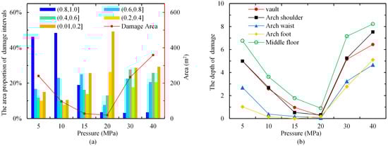
Figure 10.
Statistics of surrounding rock damage area and depth under different hydrostatic pressures: (a) proportion of different damage intervals; (b) damage depth at different locations.
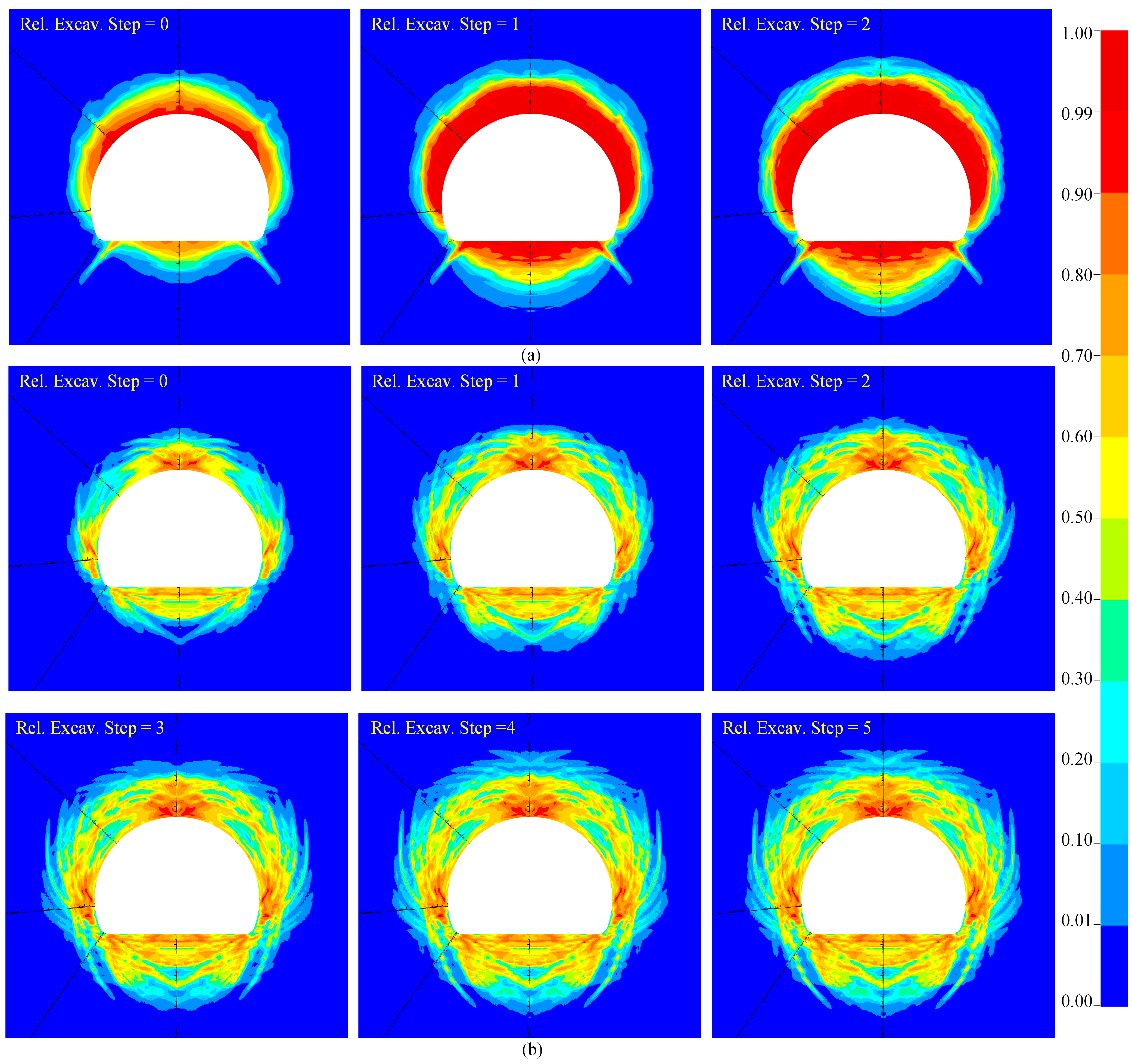
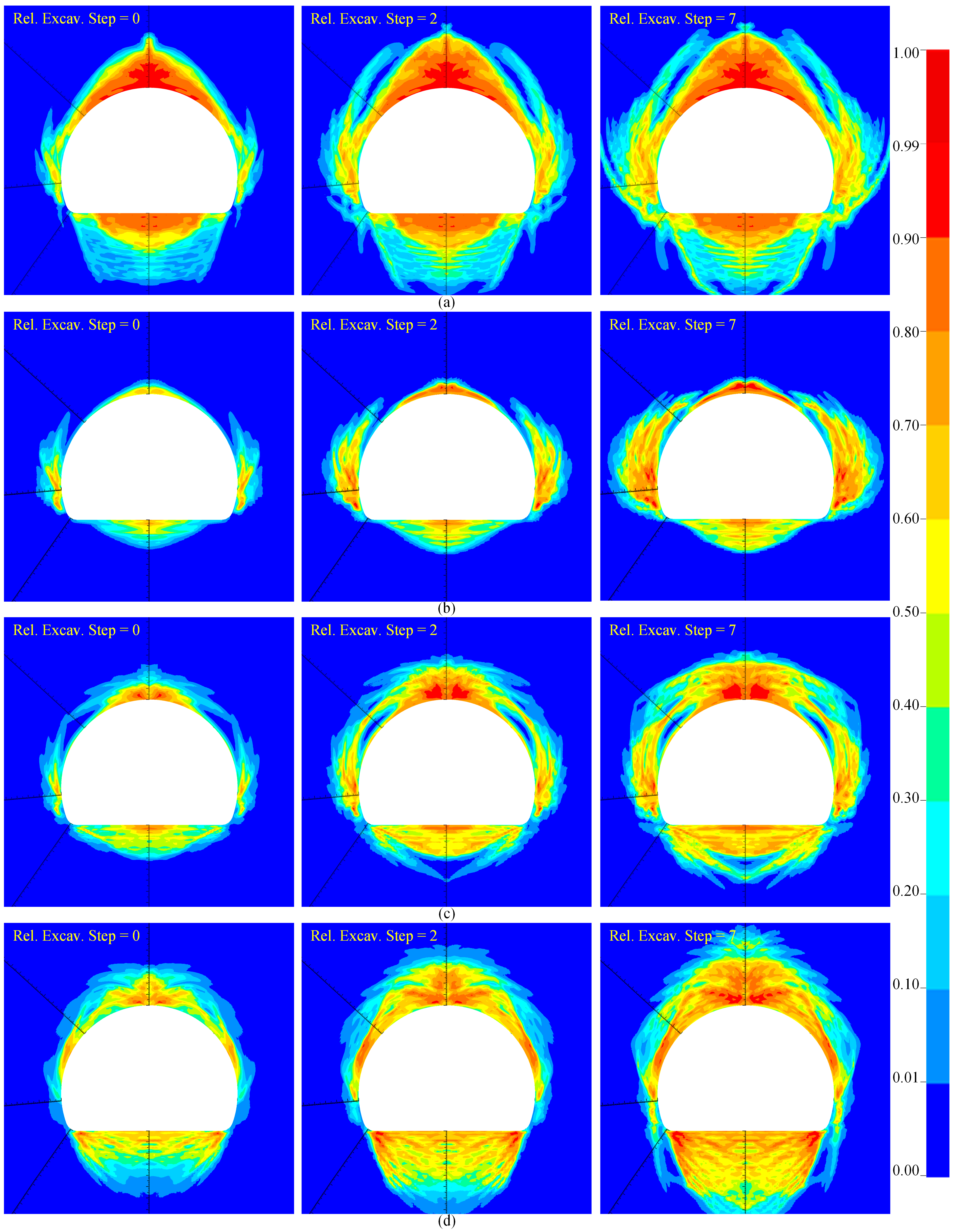
Figure 11 illustrates the evolution of tunnel-surrounding rock damage under different hydrostatic pressure conditions: Figure 11a depicts the damage progression under low hydrostatic pressure (5 MPa), while Figure 11b shows the damage evolution under high hydrostatic pressure (40 MPa) throughout the excavation process. The “relative excavation step” in the figures represents different time points corresponding to the advancing position of the tunnel face during sequential excavation. As shown in Figure 11a, under low hydrostatic pressure (5 MPa), significant damage appears immediately after the initial excavation (relative excavation step = 0), mainly concentrated in the vault and arch shoulder regions, with damage values close to 1, forming pronounced damage zones. As the tunnel face advances (relative excavation steps = 1 and 2), the damage zone slightly expands and begins to stabilize, with limited increases in damage intensity and extent. This indicates that under low hydrostatic pressure, damage induced by the blasting develops rapidly and stabilizes quickly, suggesting a relatively simple damage evolution process. In contrast, Figure 11b shows that under high hydrostatic pressure (40 MPa), the damage evolution of the surrounding rock exhibits distinctly different characteristics. After the initial excavation (relative excavation step = 0), the damage area is limited and mild. However, as the tunnel face progresses (relative excavation steps = 1–5), the unloading effect becomes more pronounced, leading to significant increases in both the extent and severity of damage, accompanied by the development of shear failure bands. Throughout the tunnel face advancement, damage in the surrounding rock continues to expand and only stabilizes after several excavation steps, reaching a final equilibrium state. This evolution pattern indicates that under high hydrostatic pressure, excavation-induced unloading triggers dominant shear failure, with the damage process exhibiting strong time dependence and cumulative effects. In summary, the evolution of surrounding rock damage varies significantly under different hydrostatic pressure conditions. Under low hydrostatic pressure, damage evolves rapidly and quickly stabilizes, whereas under high hydrostatic pressure, the damage undergoes a complex and progressive expansion process, ultimately stabilizing with shear failure as the dominant mechanism.
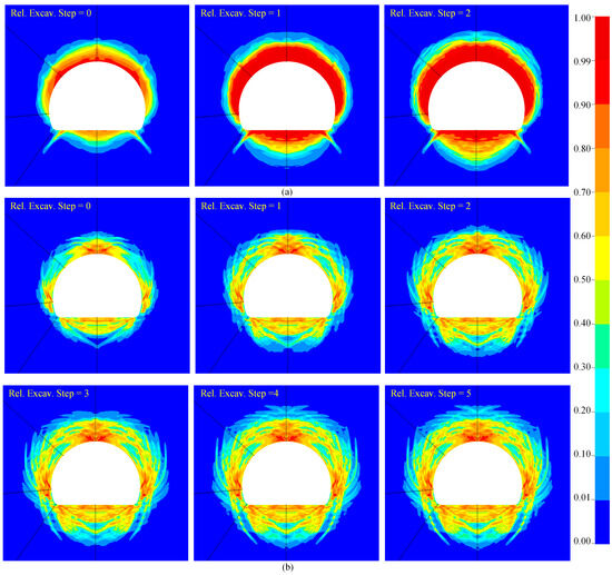
Figure 11.
Evolution of surrounding rock damage: (a) pressure = 5 MPa; (b) pressure = 40 MPa.
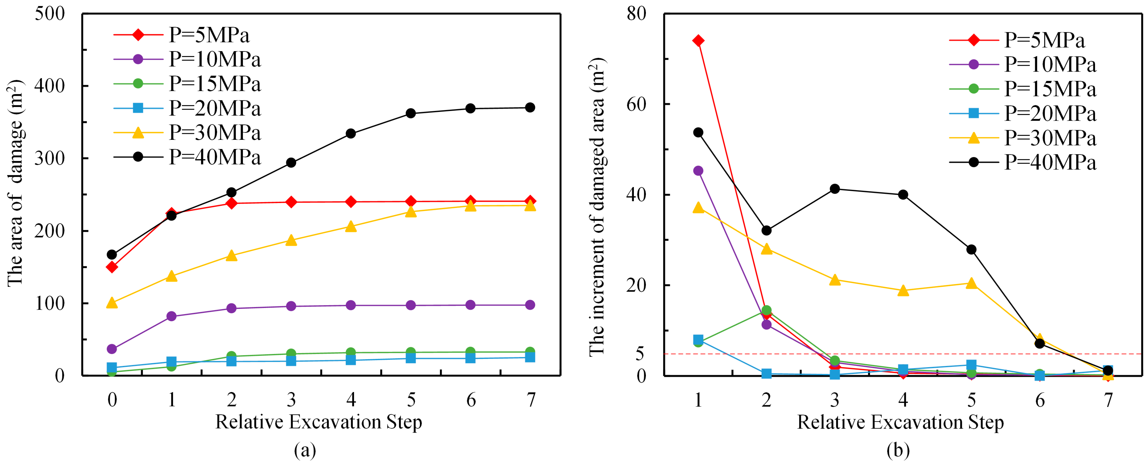
Figure 12a shows the statistical evolution of the surrounding rock damage area under various hydrostatic pressure conditions during tunnel excavation. The horizontal axis denotes the relative excavation step, while the vertical axis represents the damage area. Each curve in the figure corresponds to a different hydrostatic pressure condition, ranging from 5 MPa to 40 MPa. As shown in Figure 12a, under low hydrostatic pressures (e.g., 5 MPa and 10 MPa), the damage area increases rapidly in the early excavation stages, with final damage areas of about 240 m2 at 5 MPa and 96 m2 at 10 MPa. This indicates that under low hydrostatic pressure, blasting loads induce rapid and extensive damage to the surrounding rock. As the hydrostatic pressure increases to 15 MPa and 20 MPa, the damage area decreases significantly and remains almost unchanged with further excavation steps. This suggests that at moderate hydrostatic pressure, the confining effect is prominent, and both blasting and subsequent unloading have minimal impact on damage area expansion. However, as the hydrostatic pressure rises to 30 MPa and 40 MPa, the damage area increases again and exhibits a clear cumulative effect: the damage area continues to grow with each excavation step and only stabilizes after multiple cycles. This trend is particularly evident under the 40 MPa condition, where the damage area gradually increases to approximately 366 m2. Figure 12b illustrates how the damage area increases under different hydrostatic pressures. According to the figure, if stability is defined as an increase in damage area of less than 5 m2, the surrounding rock reaches stability within three excavation cycles when the hydrostatic pressure is 20 MPa or lower; specifically, when the hydrostatic pressure is 20 MPa, stability is achieved within just two excavation cycles. At hydrostatic pressures of 30 MPa and 40 MPa, the surrounding rock reaches stability after seven excavation cycles. Since each excavation cycle advances the tunnel face by 4.2 m, it follows that when hydrostatic pressure is 20 MPa or less, stability is reached beyond 12.6 m from the tunnel face, while under 30 MPa and 40 MPa, this distance increases to 29.4 m. This phenomenon suggests that under high hydrostatic pressure, the excavation-induced unloading effect becomes the dominant factor, leading to the progressive formation of extensive shear failure zones. In summary, the results reveal a clear nonlinear trend in damage area evolution with changing hydrostatic pressure: under low hydrostatic pressure, the damage area is large and stabilizes quickly; under moderate pressure, it is minimal and stable; and under high pressure, the damage area increases again and continues to accumulate over time.
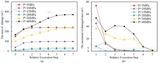
Figure 12.
Damage evolution under different hydrostatic pressures: (a) the area of damage; (b) the increment of damaged area.
4.2. Rock Damage Under Different Lateral Pressures
4.2.1. Influence of Different Lateral Pressure Coefficients on Surrounding Rock Damage
In practical engineering, tunnel-surrounding rocks are typically subjected to complex stress conditions under non-hydrostatic pressure states. Therefore, investigating the distribution characteristics of surrounding rock damage under various lateral pressure coefficients provides essential engineering guidance for tunnel design and construction safety. The lateral pressure coefficient is defined as λ = σH/σv, where σH is assumed to be equal to σh, and the vertical principal stress σv is maintained at 30 MPa.
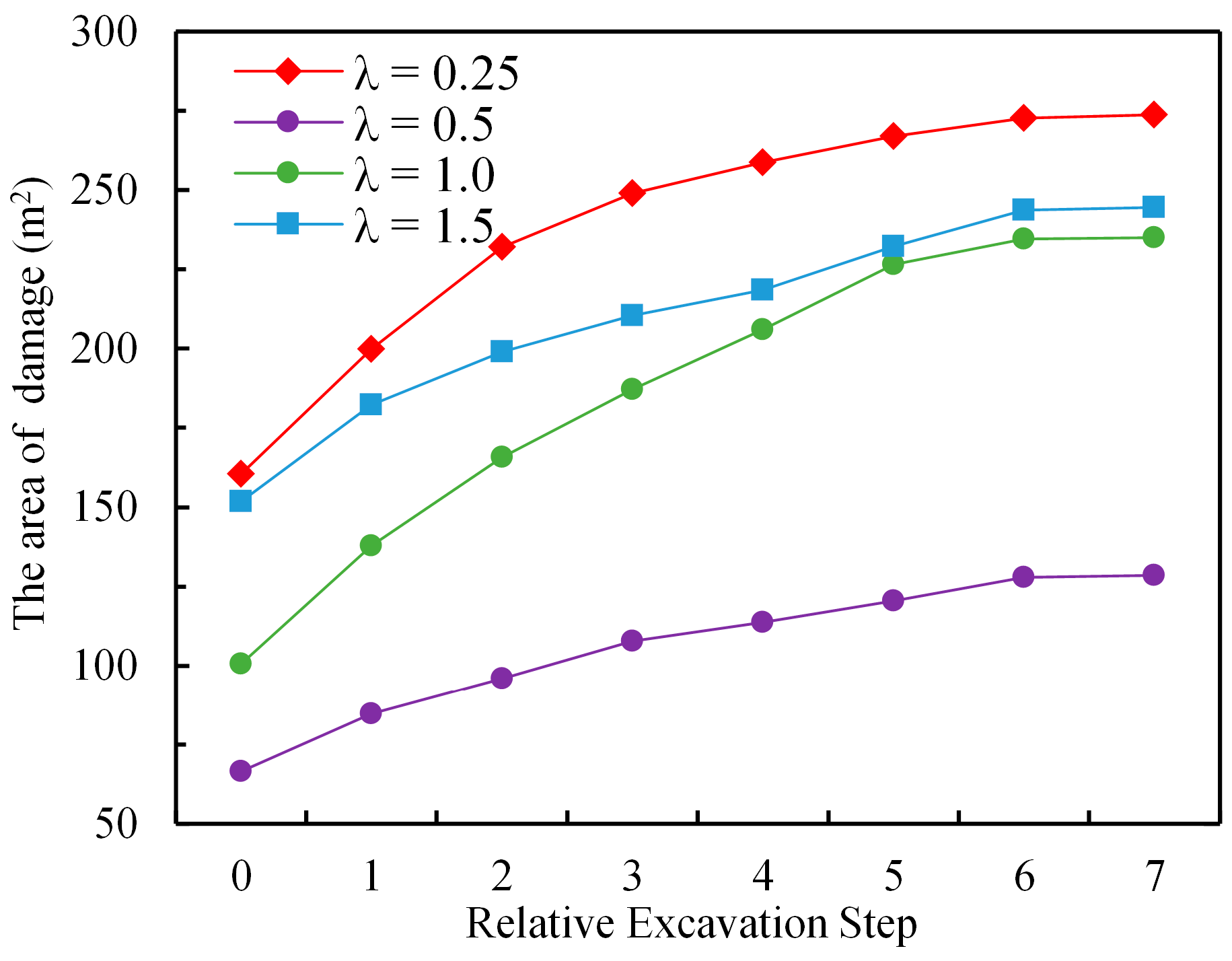
Figure 13a–d illustrates the damage distribution characteristics of the surrounding rock when the lateral pressure coefficient λ is set to 0.25, 0.5, 1.0, and 1.5. When λ = 0.25 (Figure 13a), initial excavation induces severe damage that is mainly concentrated in the vault and invert regions of the tunnel. Only slight damage is observed on the sidewalls, but the extent of the damage progressively expands as the tunnel face advances. As shown by the red curve in Figure 14, the damage area increases rapidly for relative excavation steps less than 2, then gradually slows and stabilizes at 273 m2. When λ = 0.5 (Figure 13b), initial rock damage is primarily located in the sidewall region and expands progressively as the tunnel face advances. As indicated by the purple curve in Figure 14, the damage area grows rapidly for relative excavation steps less than 3, then the growth rate slows and stabilizes at 128 m2. When λ = 1.0 (Figure 13c), the initial damage is relatively uniformly distributed around the tunnel. As excavation proceeds, the damage zones expand in multiple directions and stabilize at step 6, with a final damage area of 235 m2 (as shown by the green curve in Figure 14). When λ = 1.5 (Figure 13d), initial rock damage occurs mainly at the vault and invert with low severity, and slight damage is observed at the sidewalls. As excavation continues, damage expands in the vault and invert and stabilizes at step 6, with a final damage area of 244 m2 (blue curve in Figure 14). Overall, under lower lateral pressure coefficients, the damage is concentrated at the vault and invert with dominant tensile failure, while the sidewalls exhibit minor shear damage. As the lateral pressure coefficient increases, the damage mechanism gradually transitions to shear-dominated failure.

Figure 13.
Damage characteristics of surrounding rock when σH = σh: (a) σH = σh = 7.5 MPa, σv = 30 MPa; (b) σH = σh = 15 MPa, σv = 30 MPa; (c) σH = σh = 30 MPa, σv = 30 MPa; (d) σH = σh = 45 MPa, σv = 30 MPa.
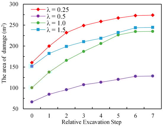
Figure 14.
Damage area evolution under different lateral pressure coefficients.
4.2.2. Influence of Different σh on Surrounding Rock Damage
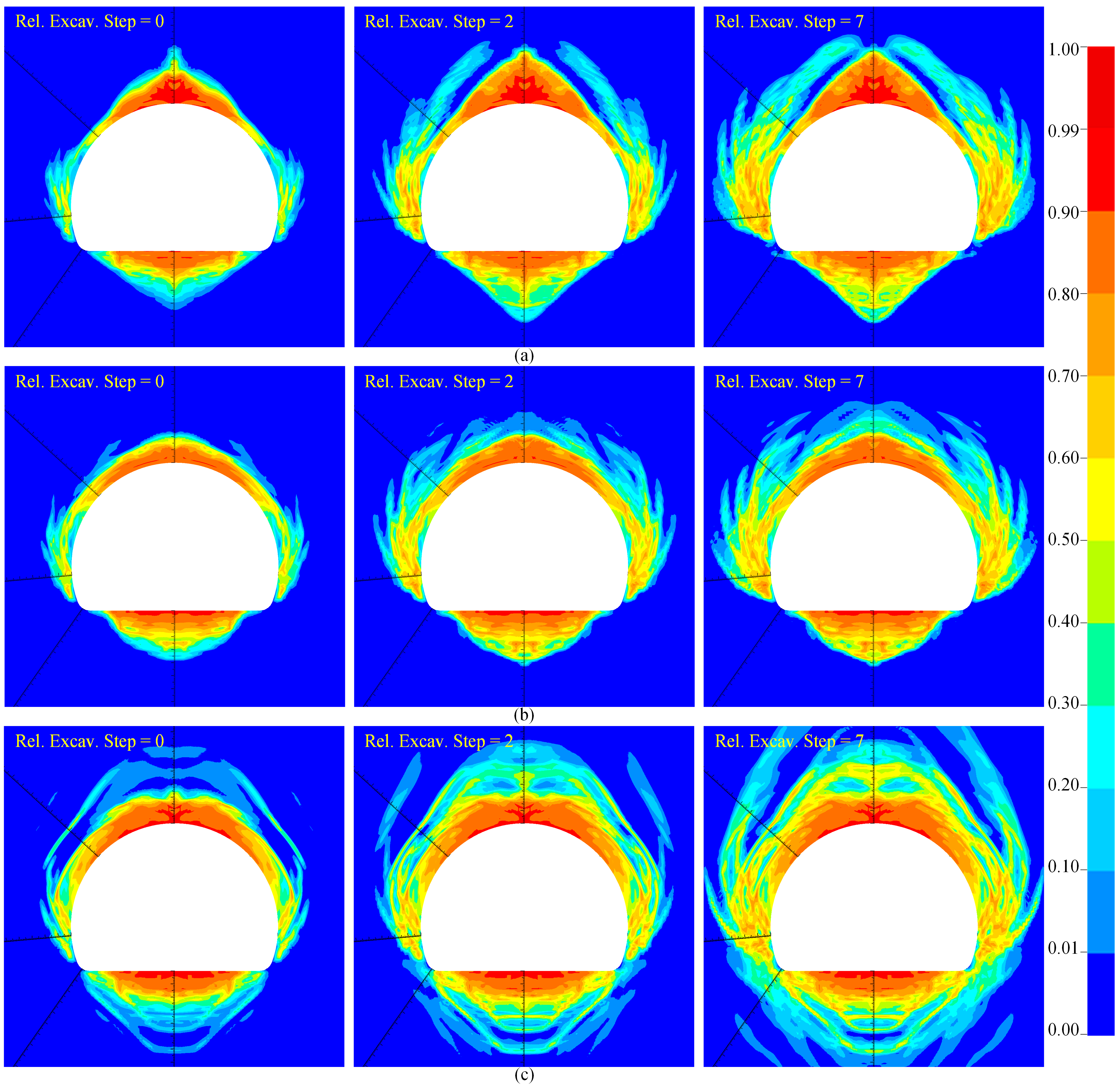
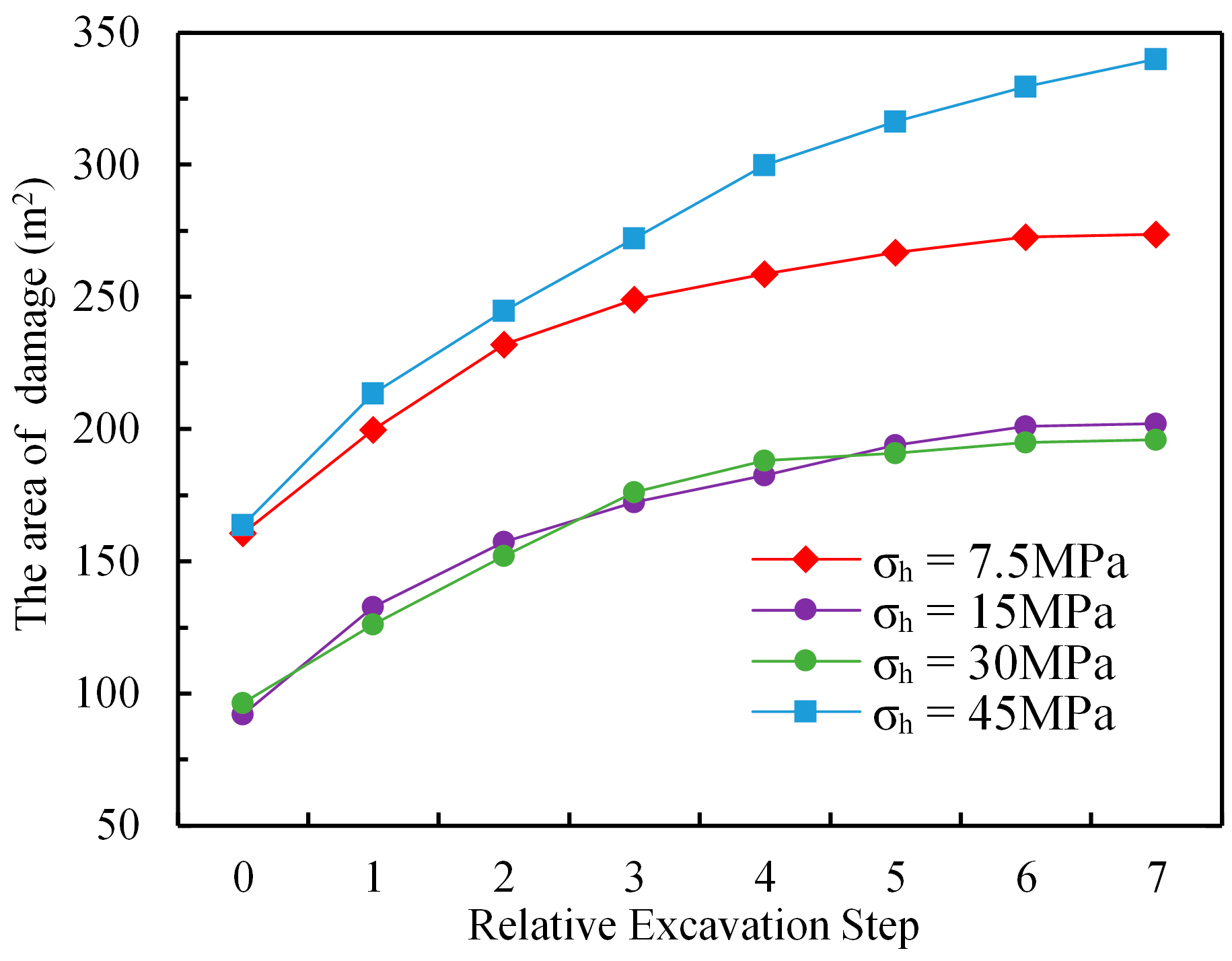
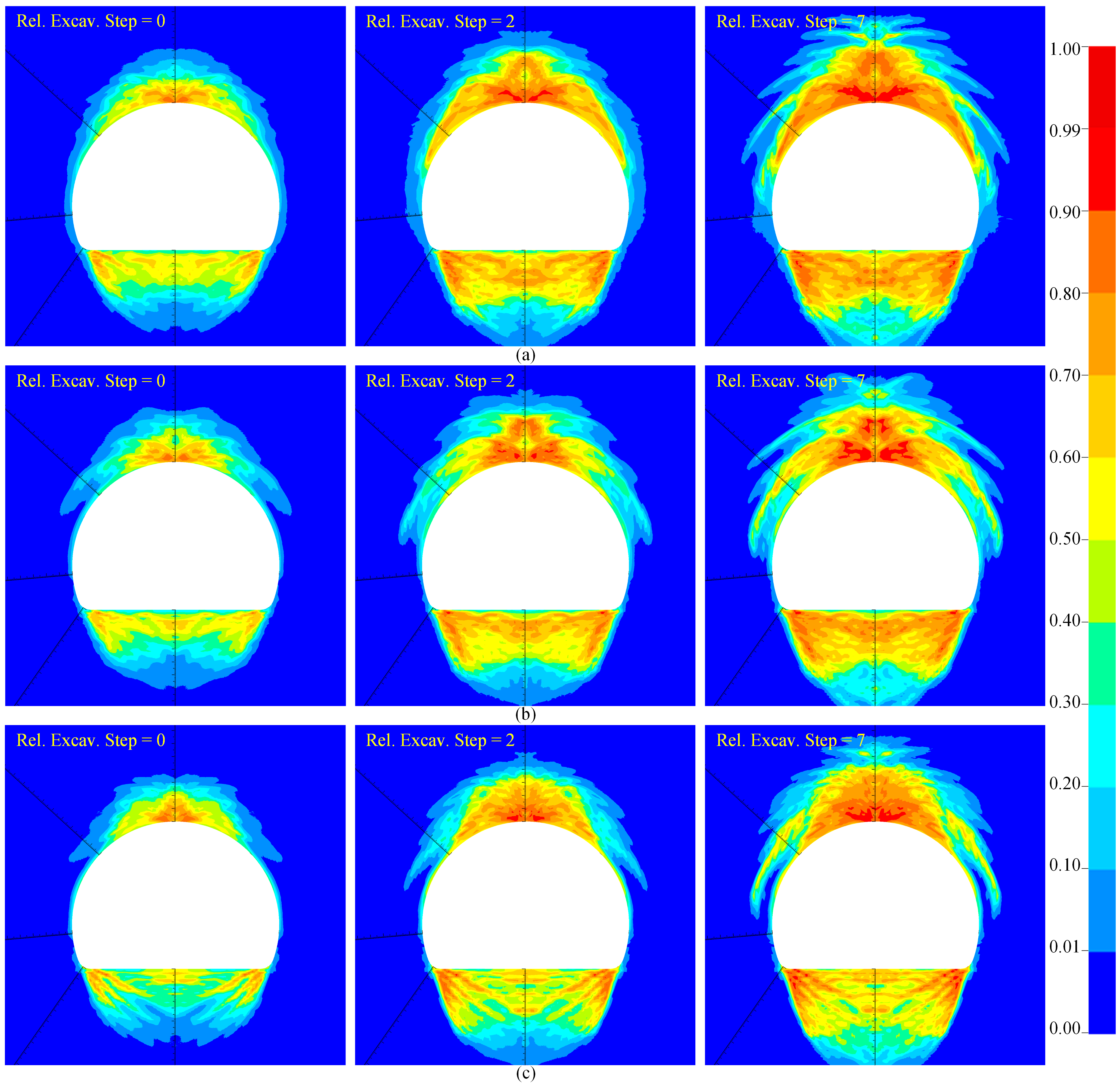
The influence of axial stress on tunnel-surrounding rock damage is often overlooked, particularly in traditional two-dimensional numerical simulations. Figure 15a–c illustrate the evolution of surrounding rock damage under a constant transverse stress σH = 7.5 MPa and varying axial stresses σh of 15 MPa, 30 MPa, and 45 MPa, respectively. As shown in Figure 15a (σh = 15 MPa), the surrounding rock primarily exhibits tensile failure at the vault and invert, and shear failure at the sidewalls and shoulders. The shear zone at the sidewalls expands markedly with tunnel face advancement, resulting in a final damage area of 202 m2 (see the purple curve in Figure 16). When σh increases to 30 MPa, the damage evolution trend remains similar, but the overall damage extent slightly decreases (Figure 15b), with a final damage area of 196 m2 (green curve in Figure 16). At σh = 45 MPa, multiple discontinuous damage bands emerge around the tunnel and expand continuously with face advancement, resulting in a significantly enlarged damage area (see Figure 15c). At relative excavation step 7, the damage area reaches 340 m2, and the blue curve in Figure 16 indicates that damage stabilization has not yet been achieved. Therefore, it can be concluded that under conditions where σH < σv, the axial horizontal stress σh exerts a significant influence on the evolution of surrounding rock damage.

Figure 15.
Damage characteristics of surrounding rock (σH = 7.5 MPa, σv = 30 MPa): (a) σh = 15 MPa; (b) σh = 30 MPa; (c) σh = 45 MPa.
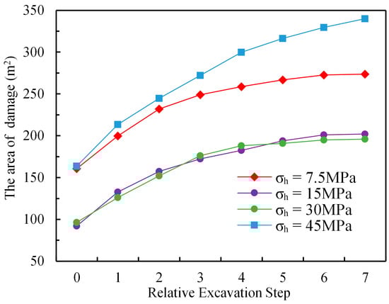
Figure 16.
Damage area evolution under different σh (σH = 7.5 MPa, σv = 30 MPa).
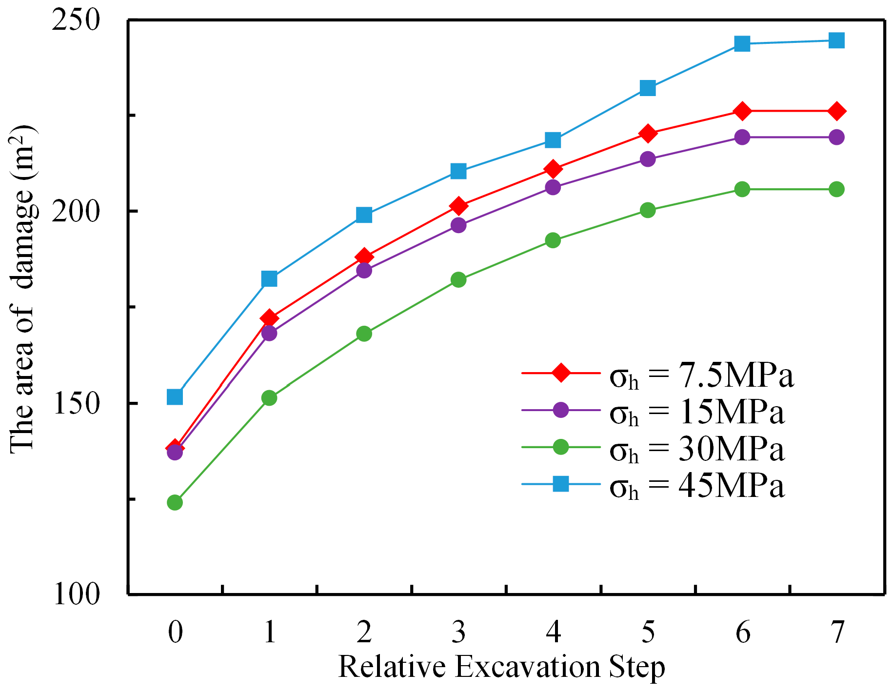
Figure 17a–c show the evolution of surrounding rock damage under a fixed transverse horizontal stress σH = 45 MPa and axial stresses σh of 7.5 MPa, 15 MPa, and 30 MPa, respectively. As observed in Figure 17a–c, the damage evolution under these three stress states is largely consistent. Initial damage is concentrated at the vault and invert, and expands progressively with tunnel face advancement. The final damage areas for all three cases fall within the range of 200–250 m2, as illustrated in Figure 18. It can, therefore, be concluded that when σH > σv, the axial stress σh has a relatively limited influence on the damage evolution of the surrounding rock.
Figure 17.
Damage characteristics of surrounding rock (σH = 45 MPa, σv = 30 MPa): (a) σh = 7.5 MPa; (b) σh = 15 MPa; (c) σh = 30 MPa.
Figure 18.
Damage area evolution under different σh (σH = 45 MPa, σv = 30 MPa).
5. Discussion
The failure mechanisms and damage evolution patterns of rock masses vary significantly under different hydrostatic pressures and lateral pressure coefficients. Although the existing studies differ in methodology and focus, they exhibit consistent overall trends, with clear mechanical explanations accounting for the differences. Li et al. [44], through theoretical analysis and numerical simulation using the RHT model, showed that increasing hydrostatic pressure significantly enhances the dynamic compressive strength of rock masses and restricts the propagation of tensile stress waves. As a result, the radius of the crushed zone and the extent of fracturing decrease notably, connectivity between cracks is hindered, and blasting efficiency is significantly reduced. In contrast, Hong et al. [1], based on field acoustic tests and numerical inversion, found that higher hydrostatic pressure causes more severe stress redistribution and unloading disturbances, which substantially enhance shear yielding in the surrounding rock. This leads to deeper EDZ and more pronounced zonal failure structures. Integrating both findings, this study identifies a nonlinear response of rock damage to hydrostatic pressure, initially decreasing and then increasing. At medium-to-low pressures, enhanced confinement effectively suppresses blasting-induced damage; at high pressures, however, unloading-induced shear failure dominates, leading to the gradual expansion of the damage zone across excavation cycles. This finding reveals that in situ stresses influence blasting outcomes not only by suppressing tensile stress-induced failure but also by modulating the development and distribution of shear failure through unloading effects.
Regarding variations in lateral pressure coefficients, Li et al. [44] demonstrated that under high values, blasting-induced fractures preferentially propagate along the principal stress direction (typically vertical), significantly reducing fracture connectivity in the perpendicular directions. Hong et al. [1] further observed that as the lateral pressure coefficient increases, the excavation damaged zone (EDZ) gradually evolves from an isotropic circular shape to an elliptical one, accompanied by exponential growth in vertical damage depth. Zhu et al. [45] found that when the lateral pressure coefficient is 1.0, the damage zone is minimal and the surrounding rock remains optimally stable. At a coefficient of 0.2, significant tensile failure occurs at the tunnel vault, resulting in deeper damage. In contrast, when the coefficient reaches 2.0, large-scale shear failure tends to develop at both the tunnel vault and floor, causing the most severe damage. The simulation results of this study further demonstrate that the lateral pressure coefficient not only controls the spatial distribution of damage but also dictates shifts in dominant failure mechanisms. Under low-λ conditions, extensive tensile fracture zones form at the vault and floor, accompanied by multiple shear bands at the arch waist. Conversely, under high λ conditions, shear failure at the arch waist diminishes, while the tensile damage at the vault and floor gradually transitions to shear-dominated failure.
This study employed an improved HJC model, with parameter inversion and field validation based on the Hoek–Brown criterion. Although the Hoek–Brown criterion partially accounts for structural features in rock masses, its representation of joints and weak interlayers is still approximate and empirical, requiring further validation through comprehensive modeling and field testing. Moreover, this study focused solely on rock damage associated with a specific tunnel cross-sectional shape without exploring how different shapes may affect damage behavior. Future research should systematically investigate a broader range of factors influencing rock damage. Despite these limitations, this study provides new insights into the mechanisms of rock damage around tunnels under high-stress conditions.
6. Conclusions
This study proposes a modified HJC constitutive model based on the Hoek–Brown failure criterion to simulate rock damage, which is implemented in the dynamic finite element software LS-DYNA. Using a large-section tunnel excavation in China as a case study, the proposed model and LS-DYNA’s cumulative damage simulation technique were employed to simulate the damage evolution of the surrounding rock under cyclic blasting loads. The simulation results were validated against field test data. Subsequently, a series of numerical simulations were performed to investigate rock mass damage under various in situ stress conditions during drill-and-blast excavation, leading to the following conclusions:
- (1)
- With increasing hydrostatic pressure, the extent of the damage zone in the surrounding rock initially decreases and then expands. Under low hydrostatic pressure, blasting-induced damage dominates. As hydrostatic pressure increases, it suppresses the spread of blasting damage, thereby reducing the extent of the damage. With a further increase in stress, unloading-induced shear failure becomes dominant, resulting in a progressive expansion of the damage zone.
- (2)
- At lower hydrostatic pressure, a larger proportion of the damaged zone exhibits damage values exceeding 0.8 compared with higher pressure scenarios. For this horseshoe-shaped tunnel, the damage depth is greatest at the vault and floor and minimal at the arch waist under hydrostatic pressure. When the hydrostatic pressure is less than 20 MPa, the surrounding rock stabilizes at a distance greater than 12.6 m from the tunnel face, whereas at hydrostatic pressures of 30 MPa and 40 MPa, this distance increases to 29.4 m.
- (3)
- When σH = σh and σv = 30 MPa, under low lateral pressure coefficients, damage primarily involves tensile failure at the vault and floor and shear failure at the arch waist. As the lateral pressure coefficient increases, shear failure at the arch waist diminishes, while the extent of tensile failure at the vault and floor decreases, gradually transitioning into shear failure, which then intensifies. Overall, the damaged area decreases initially and then increases as the lateral pressure coefficient rises.
- (4)
- When σH < σv = 30 MPa and σh < σv, the damage characteristics resemble those under low lateral pressure: tensile failure occurs at the vault and floor, and shear failure at the arch waist and arch shoulder. However, when σh ≥ σv, shear failure intensifies at the arch waist, forming multiple long shear damage zones. When σH > σv = 30 MPa, increases in σh have a limited influence on the extent of the damage. Thus, when the horizontal stress perpendicular to the tunnel exceeds the vertical stress, the axial stress has a negligible effect on the extent of surrounding rock damage.
Based on these conclusions, the design and construction of deeply buried tunnels should fully account for the influence of varying in situ stress conditions on rock damage mechanisms, ensuring an appropriate match between blasting parameters and support systems. In regions with low hydrostatic pressure, precautions should be taken against blasting-induced tensile failures, with reinforcement appropriately strengthened at the vault and floor. Conversely, under high hydrostatic pressure and high lateral pressure ratios, attention should be directed toward progressive shear failure induced by unloading. The timely installation of flexible support systems that accommodate the gradual evolution of damage is recommended. Additionally, it is recommended that three-dimensional stress measurements and numerical inversions be performed during the design phase. Excavation schedules and blasting plans should be dynamically adjusted based on simulation results, and multiple rounds of damage monitoring should be implemented during construction to effectively predict and control rock damage, thereby enhancing the overall stability and durability of the tunnel structure.
Author Contributions
Conceptualization, P.Z. and C.Z.; methodology, W.C., C.H. and C.Z.; validation, P.Z., Y.L. and Z.C.; formal analysis, P.Z., Y.L. and Z.C.; investigation, W.C., C.H., C.Z., Y.L. and Z.C.; writing—original draft, P.Z.; writing—review and editing, W.C., C.H., C.Z., Y.L. and Z.C.; visualization: P.Z., Y.L. and Z.C.; supervision: C.H.; project administration: W.C.; funding acquisition: W.C. and C.Z. All authors have read and agreed to the published version of the manuscript.
Funding
This work was supported by the Postdoctoral Fund of the Power China Chengdu Engineering Corporation Limited (Grant No. P60324).
Data Availability Statement
The original contributions presented in this study are included in the article. Further inquiries can be directed to the corresponding author.
Conflicts of Interest
Authors Penglin Zhang, Chong Zhang, Weitao Chen and Chunhui He were employed by Power China Chengdu Engineering Corporation Limited. The remaining authors declare that the research was conducted in the absence of any commercial or financial relationships that could be construed as a potential conflict of interest.
References
- Hong, Z.; Tao, M.; Wu, C.; Zhou, J.; Wang, D. The Spatial Distribution of Excavation Damaged Zone around Underground Roadways during Blasting Excavation. Bull. Eng. Geol. Environ. 2023, 82, 155. [Google Scholar] [CrossRef]
- Li, S.; Ling, T.; Liu, D.; Liang, S.; Zhang, R.; Huang, B.; Liu, K. Determination of Rock Mass Parameters for the RHT Model Based on the Hoek–Brown Criterion. Rock Mech. Rock Eng. 2023, 56, 2861–2877. [Google Scholar] [CrossRef]
- Cui, Y.; Wu, B.; Meng, G.; Xu, S. Research on Blasting Cumulative Dynamic Damage of Surrounding Rock in Step Construction Tunnel. Sci. Rep. 2023, 13, 1974. [Google Scholar] [CrossRef] [PubMed]
- Ji, L.; Yao, Y.; Zhou, C.; Zhang, Z.; Cao, H.; Wu, T. Research on Cumulative Damage Effects and Safety Criterion of Surrounding Rock in Bench Blasting of a Large Cross-Section Tunnel. Alex. Eng. J. 2024, 108, 626–639. [Google Scholar] [CrossRef]
- Martino, J.B.; Chandler, N.A. Excavation-Induced Damage Studies at the Underground Research Laboratory. Int. J. Rock Mech. Min. Sci. 2004, 41, 1413–1426. [Google Scholar] [CrossRef]
- Yang, J.H.; Yao, C.; Jiang, Q.H.; Lu, W.B.; Jiang, S.H. 2D Numerical Analysis of Rock Damage Induced by Dynamic In-Situ Stress Redistribution and Blast Loading in Underground Blasting Excavation. Tunn. Undergr. Space Technol. 2017, 70, 221–232. [Google Scholar] [CrossRef]
- Yang, J.; Lu, W.; Hu, Y.; Chen, M.; Yan, P. Numerical Simulation of Rock Mass Damage Evolution during Deep-Buried Tunnel Excavation by Drill and Blast. Rock Mech. Rock Eng. 2015, 48, 2045–2059. [Google Scholar] [CrossRef]
- Ji, L.; Zhou, C.; Lu, S.; Jiang, N.; Gutierrez, M. Numerical Studies on the Cumulative Damage Effects and Safety Criterion of a Large Cross-Section Tunnel Induced by Single and Multiple Full-Scale Blasting. Rock Mech. Rock Eng. 2021, 54, 6393–6411. [Google Scholar] [CrossRef]
- Yan, P.; Lu, W.; Chen, M.; Hu, Y.; Zhou, C.; Wu, X. Contributions of In-Situ Stress Transient Redistribution to Blasting Excavation Damage Zone of Deep Tunnels. Rock Mech. Rock Eng. 2015, 48, 715–726. [Google Scholar] [CrossRef]
- Kipp, M.E.; Grady, D.E. Numerical Studies of Rock Fragmentation; Sandia National Laboratories: Albuquerque, NM, USA, 1980.
- Grady, D.E.; Kipp, M.E. Mechanisms of Dynamic Fragmentation: Factors Governing Fragment Size. Mech. Mater. 1985, 4, 311–320. [Google Scholar] [CrossRef]
- Taylor, L.M.; Chen, E.-P.; Kuszmaul, J.S. Microcrack-Induced Damage Accumulation in Brittle Rock under Dynamic Loading. Comput. Methods Appl. Mech. Eng. 1986, 55, 301–320. [Google Scholar] [CrossRef]
- Kuszmaul, J.S. A New Constitutive Model for Fragmentation of Rock Under Dynamic Loading; Sandia National Laboratories: Albuquerque, NM, USA, 1987.
- Thorne, B.J.; Hommert, P.J.; Brown, B. Experimental and Computational Investigation of the Fundamental Mechanisms of Cratering; Sandia National Laboratories: Albuquerque, NM, USA, 1990. [CrossRef]
- Krajcinovic, D.; Silva, M.A.G. Statistical Aspects of the Continuous Damage Theory. Int. J. Solids Struct. 1982, 18, 551–562. [Google Scholar] [CrossRef]
- Xie, L.X.; Lu, W.B.; Zhang, Q.B.; Jiang, Q.H.; Wang, G.H.; Zhao, J. Damage Evolution Mechanisms of Rock in Deep Tunnels Induced by Cut Blasting. Tunn. Undergr. Space Technol. 2016, 58, 257–270. [Google Scholar] [CrossRef]
- Lyu, G.; Zhou, C.; Jiang, N. Experimental and Numerical Study on Tunnel Blasting Induced Damage Characteristics of Grouted Surrounding Rock in Fault Zones. Rock Mech. Rock Eng. 2023, 56, 603–617. [Google Scholar] [CrossRef]
- Johnson, G.R.; Holmquist, T.J. Response of Boron Carbide Subjected to Large Strains, High Strain Rates, and High Pressures. J. Appl. Phys. 1999, 85, 8060–8073. [Google Scholar] [CrossRef]
- Liu, K.; Wu, C.; Li, X.; Li, Q.; Fang, J.; Liu, J. A Modified HJC Model for Improved Dynamic Response of Brittle Materials under Blasting Loads. Comput. Geotech. 2020, 123, 103584. [Google Scholar] [CrossRef]
- Yilmaz, O.; Unlu, T. Three Dimensional Numerical Rock Damage Analysis under Blasting Load. Tunn. Undergr. Space Technol. 2013, 38, 266–278. [Google Scholar] [CrossRef]
- Wang, Z.L.; Konietzky, H. Modelling of Blast-Induced Fractures in Jointed Rock Masses. Eng. Fract. Mech. 2009, 76, 1945–1955. [Google Scholar] [CrossRef]
- Li, X.; Cao, W.; Zhou, Z.; Zou, Y. Influence of Stress Path on Excavation Unloading Response. Tunn. Undergr. Space Technol. 2014, 42, 237–246. [Google Scholar] [CrossRef]
- Zou, X.-W.; Zhou, T.; Li, G.; Hu, Y.; Deng, B.; Yang, T. Intelligent Inversion Analysis of Surrounding Rock Parameters and Deformation Characteristics of a Water Diversion Surge Shaft. Designs 2024, 8, 116. [Google Scholar] [CrossRef]
- Ma, W.-B.; Zou, W.-H.; Zhang, J.-L.; Li, G. Prediction of Shear Strength in Anisotropic Structural Planes Considering Size Effects. Designs 2025, 9, 17. [Google Scholar] [CrossRef]
- Xu, X.; Wu, Z.; Weng, L.; Chu, Z.; Liu, Q.; Zhou, Y. Numerical Investigation of Geostress Influence on the Grouting Reinforcement Effectiveness of Tunnel Surrounding Rock Mass in Fault Fracture Zones. J. Rock Mech. Geotech. Eng. 2024, 16, 81–101. [Google Scholar] [CrossRef]
- Xu, X.; Wu, Z.; Weng, L.; Chu, Z.; Liu, Q.; Wang, Z. Investigating the Impacts of Reinforcement Range and Grouting Timing on Grouting Reinforcement Effectiveness for Tunnels in Fault Rupture Zones Using a Numerical Manifold Method. Eng. Geol. 2024, 330, 107423. [Google Scholar] [CrossRef]
- Ma, G.W.; An, X.M. Numerical Simulation of Blasting-Induced Rock Fractures. Int. J. Rock Mech. Min. Sci. 2008, 45, 966–975. [Google Scholar] [CrossRef]
- Lu, W.; Yang, J.; Chen, M.; Zhou, C. An Equivalent Method for Blasting Vibration Simulation. Simul. Model. Pract. Theory 2011, 19, 2050–2062. [Google Scholar] [CrossRef]
- Yang, J.; Xia, Y.; Chen, Z.; Chen, D.; Pei, Y.; Zhu, W. Dynamic Behavior of Road High Cutting Rock Slope under the Influence of Blasting for Excavation. Procedia Earth Planet. Sci. 2012, 5, 25–31. [Google Scholar] [CrossRef]
- Yang, J.; Lu, W.; Jiang, Q.; Yao, C.; Jiang, S.; Tian, L. A Study on the Vibration Frequency of Blasting Excavation in Highly Stressed Rock Masses. Rock Mech. Rock Eng. 2016, 49, 2825–2843. [Google Scholar] [CrossRef]
- Lu, W.; Yang, J.; Yan, P.; Chen, M.; Zhou, C.; Luo, Y.; Jin, L. Dynamic Response of Rock Mass Induced by the Transient Release of In-Situ Stress. Int. J. Rock Mech. Min. Sci. 2012, 53, 129–141. [Google Scholar] [CrossRef]
- Persson, P.-A.; Holmberg, R.; Lee, J. Rock Blasting and Explosives Engineering; CRC Press: Boca Raton, FL, USA, 2018; ISBN 0203740513. [Google Scholar] [CrossRef]
- Martin, C.D.; Kaiser, P.K.; McCreath, D.R. Hoek-Brown Parameters for Predicting the Depth of Brittle Failure around Tunnels. Can. Geotech. J. 1999, 36, 136–151. [Google Scholar] [CrossRef]
- Hoek, E.; Carranza-Torres, C.; Corkum, B. Hoek-Brown Failure Criterion-2002 Edition. Proc. NARMS-Tac 2002, 1, 267–273. [Google Scholar] [CrossRef]
- Zhang, Q.B.; Zhao, J. A Review of Dynamic Experimental Techniques and Mechanical Behaviour of Rock Materials. Rock Mech. Rock Eng. 2014, 47, 1411–1478. [Google Scholar] [CrossRef]
- Xie, L.X.; Lu, W.B.; Zhang, Q.B.; Jiang, Q.H.; Chen, M.; Zhao, J. Analysis of Damage Mechanisms and Optimization of Cut Blasting Design under High In-Situ Stresses. Tunn. Undergr. Space Technol. 2017, 66, 19–33. [Google Scholar] [CrossRef]
- Livermore Software Technology Corporation (LSCT). LS-DYNA, version 971; Keyword User’s Manual; Livermore Software Technology Corporation (LSCT): Livermore, CA, USA, 2012; Volume I. [Google Scholar]
- Zhu, B.; Zhou, C.; Jiang, N. Dynamic Response Characteristics and Safety Control of Mortar Bolts under the Action of Tunnel Blasting Excavation. J. Vib. Eng. 2023, 36, 235–246. [Google Scholar] [CrossRef]
- Mustapha, S.; Ye, L. Leaky and Non-Leaky Behaviours of Guided Waves in CF/EP Sandwich Structures. Wave Motion 2014, 51, 905–918. [Google Scholar] [CrossRef]
- Ji, L.; Zhou, C.; Lu, S.; Jiang, N.; Li, H. Modeling Study of Cumulative Damage Effects and Safety Criterion of Surrounding Rock under Multiple Full-Face Blasting of a Large Cross-Section Tunnel. Int. J. Rock Mech. Min. Sci. 2021, 147, 104882. [Google Scholar] [CrossRef]
- Marburg, S. Six Boundary Elements per Wavelength: Is That Enough? J. Comput. Acoust. 2002, 10, 25–51. [Google Scholar] [CrossRef]
- Bagheri, M.; Jamkhaneh, M.E.; Samali, B. Effect of seismic soil–pile–structure interaction on mid-and high-rise steel buildings resting on a group of pile foundations. Int. J. Geomech. 2018, 18, 04018103. [Google Scholar] [CrossRef]
- Yang, J.; Liu, K.; Li, X.; Liu, Z. Stress initialization methods for dynamic numerical simulation of rock mass with high in-situ stress. J. Cent. South Univ. 2020, 27, 3149–3162. [Google Scholar] [CrossRef]
- Li, X.; Zhu, Z.; Wang, M.; Wan, D.; Zhou, L.; Liu, R. Numerical Study on the Behavior of Blasting in Deep Rock Masses. Tunn. Undergr. Space Technol. 2021, 113, 103968. [Google Scholar] [CrossRef]
- Zhu, W.C.; Wei, J.; Zhao, J.; Niu, L.L. 2D Numerical Simulation on Excavation Damaged Zone Induced by Dynamic Stress Redistribution. Tunn. Undergr. Space Technol. 2014, 43, 315–326. [Google Scholar] [CrossRef]

Disclaimer/Publisher’s Note: The statements, opinions and data contained in all publications are solely those of the individual author(s) and contributor(s) and not of MDPI and/or the editor(s). MDPI and/or the editor(s) disclaim responsibility for any injury to people or property resulting from any ideas, methods, instructions or products referred to in the content. |
© 2025 by the authors. Licensee MDPI, Basel, Switzerland. This article is an open access article distributed under the terms and conditions of the Creative Commons Attribution (CC BY) license (https://creativecommons.org/licenses/by/4.0/).