3.1. Failure Modes and Phenomena of Specimens
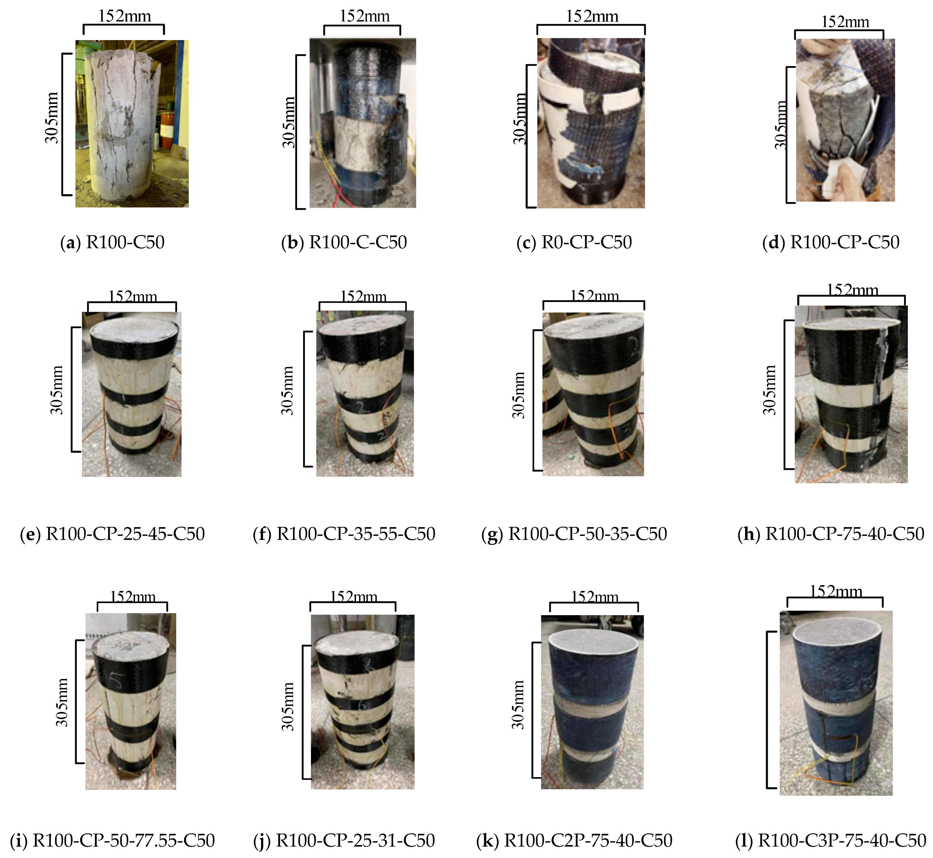
The failure states of different restrained specimens are shown in
Figure 6. When the load is increased to 659 kN, small cracks appeared in unconfined specimen R100-C50 (
Figure 6a). As the load is increased to the peak value of 843 kN, the crack widens rapidly, the concrete on the surface of the specimen falls off into flakes, and the specimen is destroyed. There is no warning before the failure.
The middle part of specimen R100-C-C50 (
Figure 6b) expands laterally and bulges when the load is increased to 1001 kN, and the RAC produces a slight cracking sound. When the load is increased to the peak load of 1213 kN, cracks appear in the middle of the CFRP and rapidly extend vertically to the bottom. As the crack length of the CFRP increases to 100 mm, the specimen fails with the fracture of the CFRP and the slamming of the RAC crushed stone. For specimens R0-CP-C50 and R100-CP-C50 (
Figure 6c,d), when the load is increased to 1274 kN and 1219 kN, the middle part of the carbon fiber begins to turn white, and the specimens have no obvious deformation. If the load is further increased to the peak load of 1341 kN and 1411 kN, the CFRP crack occurs in the middle and the crack width is extended to about 300 mm at both ends in a zigzag pattern, which is slower than that of the R100-C-C50 crack. Finally, the PVC and CFRP are destroyed at the same time, and the specimen is broken. It can be seen that CFRP-PVC plays a role in improving the ductility of the specimen.
Specimens R100-CP-25-45-C50 (
Figure 6e), R100-CP-35-55-C50 (
Figure 6f), R100-CP-50-35-C50 (
Figure 6g), and R100-CP-25-31-C50 (
Figure 6j) all fail in the same way. With the increase in load, the middle part of the specimen bulges. While the specimen fails, the core concrete cracks, the middle part of the CFRP begins to crack but does not break, and there is no obvious phenomenon of damage to the PVC.
Once the load is increased to 1310 kN, an outer bulge appears in the middle of specimen R100-CP-75-40-C50 (
Figure 6h), followed by a small crack of about 3 mm in the middle strip. The CFRP strips at both ends of the specimen do not reach the constraint limit when the load is increased to 1331 kN, and the specimen retains its bearing capacity. Subsequently, the central CFRP strip develops a serrated fracture. While the pressure is increased further, the CFRP strips at both ends crack simultaneously with the PVC, with a cracking length of 305 mm. The specimen is damaged.
There is no obvious sign of damage on the surface of specimens R100-C2P-75-40-C50 and R100-C2P-75-40-C50, and no trace of damage on the PVC tube and CFRP strips. Because of the increased number of layers of outer CFRP strips in the middle of the RAC column, the central CFRP strips do not fracture, and the failure locations of the specimens are concentrated in the inner RAC. Thus, the CFRP restraint with sufficient strip width in the middle of the specimen can make the CFRP-PVC tube fully exert its restraint effect. Since the CFRP strips are broken one by one from the middle to both ends, the specimens have better ductility.
Furthermore, the friction forces at the specimen ends against the loading plates influence the failure modes. For unconfined specimens (e.g., R100-C50), end friction restrains lateral expansion, inducing localized conical crushing at the end zones (
Figure 6a) and delaying vertical crack propagation. In CFRP strip-confined specimens (e.g., R100-CP-75-40-C50), friction enhances the confinement effectiveness of end strips, concentrating cracks within the mid-span strip gap regions. Notably, the low friction coefficient of PVC (μ ≈ 0.1) mitigates end friction effects. Conversely, fully wrapped CFRP specimens (R100-C-C50) exhibit exacerbated CFRP stress concentration due to direct CFRP-plate contact, accelerating CFRP fracture (
Figure 6b).
3.2. Axial Stress–Strain Behavior
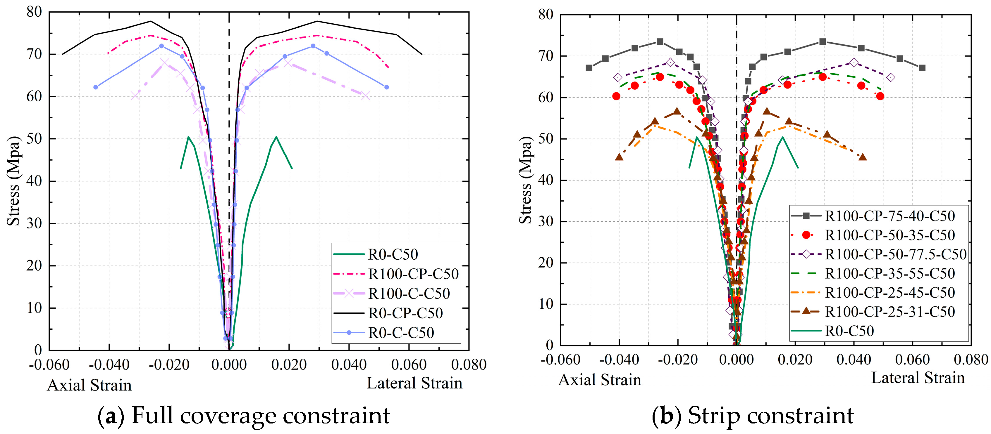
Figure 7 displays the stress–strain curves of specimens under various restrictions. The stress–strain curves of unconfined specimen R0-C50 exhibit typical unconstrained characteristics, including (1) a tiny ascending section slope, (2) almost no reinforcement phase, (3) a steep descent curve, and (4) a fast destruction of the specimen upon reaching the peak load. The compressive performance and deformation capacity of other specimens increase to varying degrees because the PVC and CFRP limit the lateral deformation of the core concrete.
When just the CFRP is constrained, as depicted in
Figure 7a, RAC specimen R100-C-C50 with 100% replacement rate performs worse in terms of deformation capacity and compressive strength than NAC specimen R0-C-C50. This is due to the fact that there are numerous microcracks inside the re-fractured RAs and the surface is coated with cement mortar, resulting in large pores, many micro cracks, and high brittleness of RAC. When cracks occur in the RAC column, uneven lateral expansion affects the confining ability of the CFRP directly in contact with the RAC column, resulting in uneven force. The core concrete strength of specimen R0-C-C50 has a greater value. Although its compressive strength is larger than that of other CFRP-PVC joint restraint specimens, the ductility is still not as excellent because as the load grows, cracks emerge inside the core concrete of the joint restraint specimen and the lateral deformation increases. At this time, the joint restraint effect of PVC and CFRP on concrete makes the bearing capacity of the specimen continue to rise. The reasons are as follows: (1) When the PVC is located between core concrete and CFRP cloth, direct contact between the CFRP and the concrete surface is avoided, local stress concentration of carbon fiber caused by uneven transverse expansion of concrete column is reduced, and the strength of the CFRP is fully utilized. Therefore, as the transverse deformation of the core concrete increases, the PVC deforms and absorbs a portion of the energy due to extrusion, leading to a certain load-holding capacity of the specimen. (2) PVC has a certain thickness and stiffness. The constraint stress of CFRP on the concrete column may be uniformly conveyed to the concrete column via PVC, avoiding partial damage of the concrete column in advance. (3) PVC has a particular toroidal tensile strength. It has a restraint effect on the concrete column before the compressive strength of the concrete column reaches the ultimate compressive strength. In addition, the effect of the RA substitution rate on the ductility of the RAC column is reduced under the combined constraints of the PVC and CFRP, and the compressive strength of R100-CP-C50 is slightly lower than that of R0-CP-C50. It can be seen from
Figure 7b that the strip width and spacing have significant influence on the compressive strength and ductility of the RAC column.
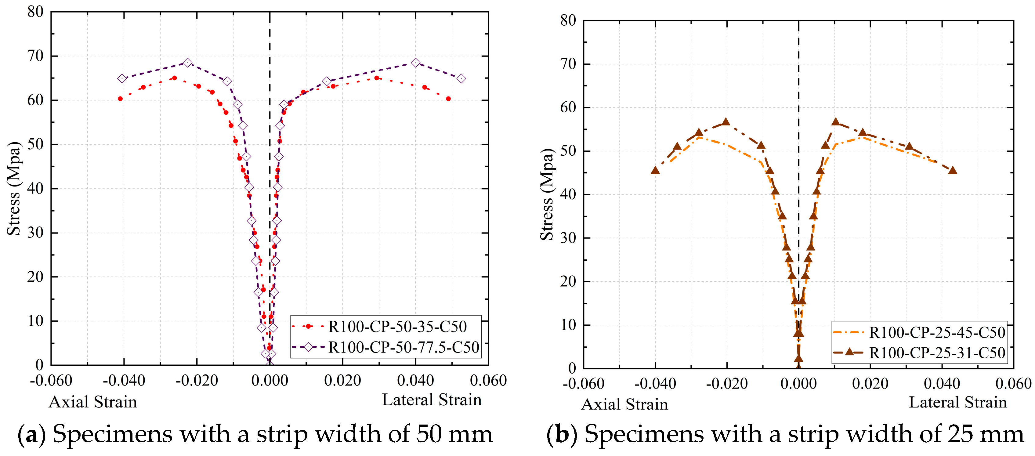
To reflect the characteristics of different strong and weak constraints,
Figure 8 depicts the stress–strain curves of the specimens with strong and weak constraints. Specimens R0-CP-C50, R100-CP-C50, R100-CP-75-40-C50, and R100-CP-75-77.5-C50 (
Figure 8a) show a typical strong constraint state: the stress rises during the curve strengthening phase, but the specimen retains some load-holding capacity. As shown in
Figure 8b, the specimens R0-C-C50, R100-C-C50, R100-CP-25-31-C50, R100-CP-25-45-C50, R100-CP-35-55-C50, and R100-C-50-35-C50 exhibit poor constraints: the curve does not rise clearly in the strengthening stage, and the specimen is softening. When compared to the weakly constrained specimens, strongly constrained specimens have higher compressive strength and ductility. Among the band restraint specimens, R100-CP-75-40-C50 and R100-CP-50-77.5-C50 are strongly restrained specimens. The reason for this is that, in comparison to other band constrained specimens (weakly constrained specimens), CFRP bands of sufficient width are attached to their outer middle.
The comparison of the restraint effects of specimens with the same strip width but varying strip spacing is shown in
Figure 9. To further explore the above mechanisms, specimens R100-CP-50-77.5-C50 and R100-CP-50-35-C50, with the same strip width, are compared (
Figure 9a), and it is found that the bands of specimen R100-CP-50-35-C50 are more densely arranged and more CFRP materials are employed. On the contrary, its compressive strength and ductility are lower than those of R100-CP-50-77.5-C50. This is related to the fact that the core stress area of specimen R100-CP-50-35-C50 is not externally attached with a CFRP band and only constrained by PVC, which causes the middle of the RAC column to be crushed in advance and fail, and the CFRP of the restraint specimen cannot fully implement its restraint effect. As shown in
Figure 9b, the load-bearing capacity of specimen R100-CP-25-45-C50 is lower than that of specimen R100-CP-25-31-C50, but the deformation capacity is similar. The axial deformation of the specimens under the constraints of a CFRP strip and PVC pipe presents a continuous “arch” distribution, so the existence of an “arch” may mean part of the load under the axial load is shared, but the total reinforcement effect is not optimum because the strip is too narrow. Therefore, the effect of strip restraint is mainly affected by whether there is a strip constraint in the middle of the specimen and the width of the strip.
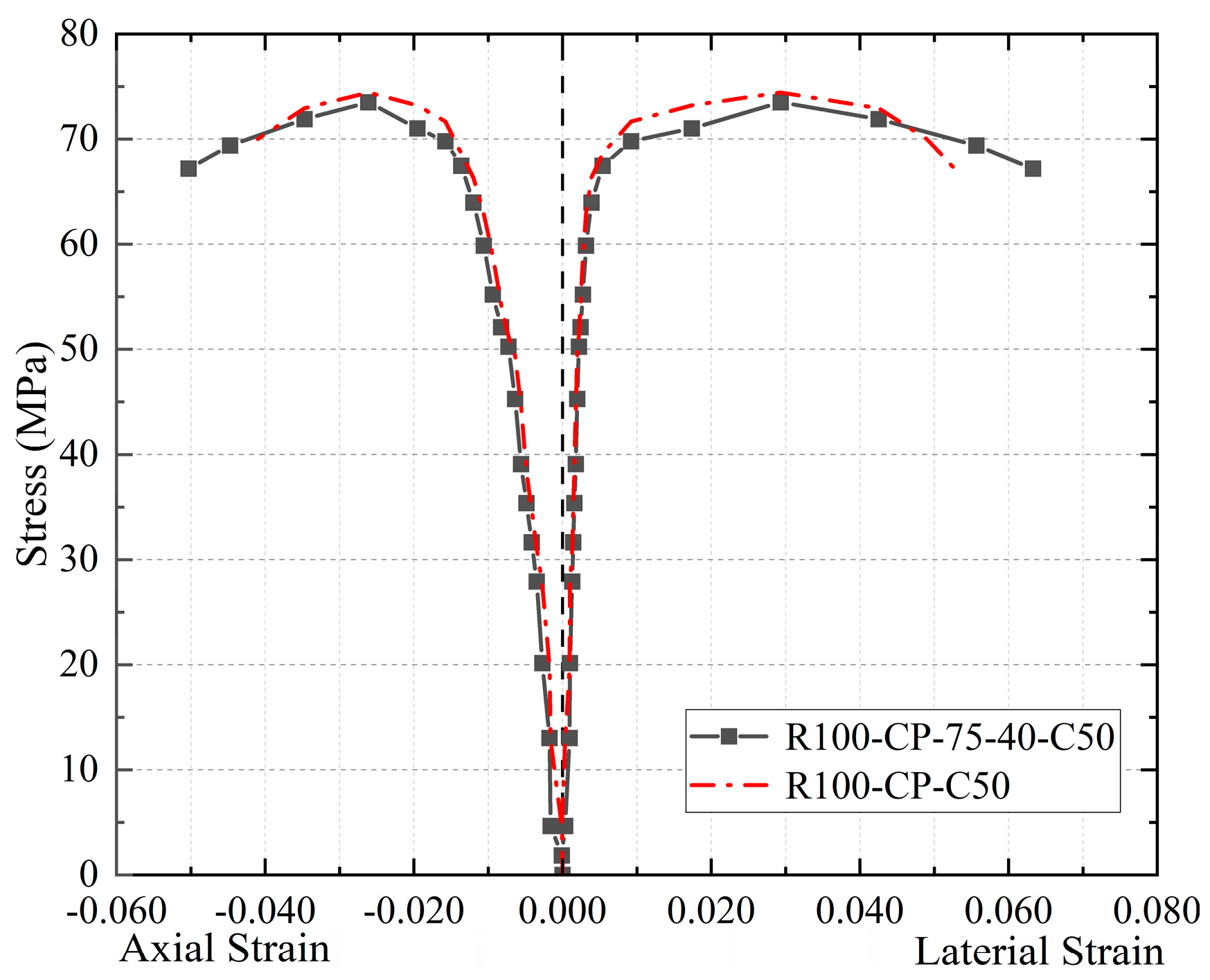
Figure 10 depicts a comparison of the stress–strain curves of the best CFRP strip restraint specimen, R100-CP-75-40-C50, in this experiment with the CFRP full-coverage restraint specimen R100-CP-C50. As can be observed, the bearing capacity of the two types of specimens is almost the same, while the strip constrained specimens have a higher deformation capacity. The reasons are as follows: (1) When the middle CFRP band reaches the constraint limit and breaks in specimen R100-CP-75-40-C50, the upper and lower CFRP bands can continue to work normally, and each CFRP band is unaffected by the other. (2) The binding force on the core concrete is non-uniform in the lateral direction due to the CFRP strip wrapping mode, and the restraint mechanism is different from that of the whole wrapped concrete. To summarize, specimens in the strip restraint mode are more economical and effective than those in the whole restraint mode.
It should be noted that the core role of CFRP strips (or full wrapping) is to provide circumferential confinement, restrict the lateral expansion of concrete, and thereby increase its axial compressive strength and ductility. Based on the above failure mechanism, the mid-region of the specimen is the part with the highest confinement demand and the most significant confinement effect. Therefore, concentrating CFRP strips in the mid-region of the specimen (especially for strip wrapping) can most effectively provide confinement force to the weakest area. The test results (as seen in
Figure 6,
Figure 8 and
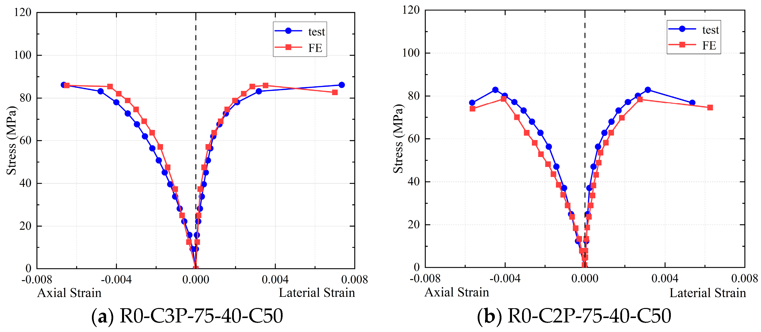
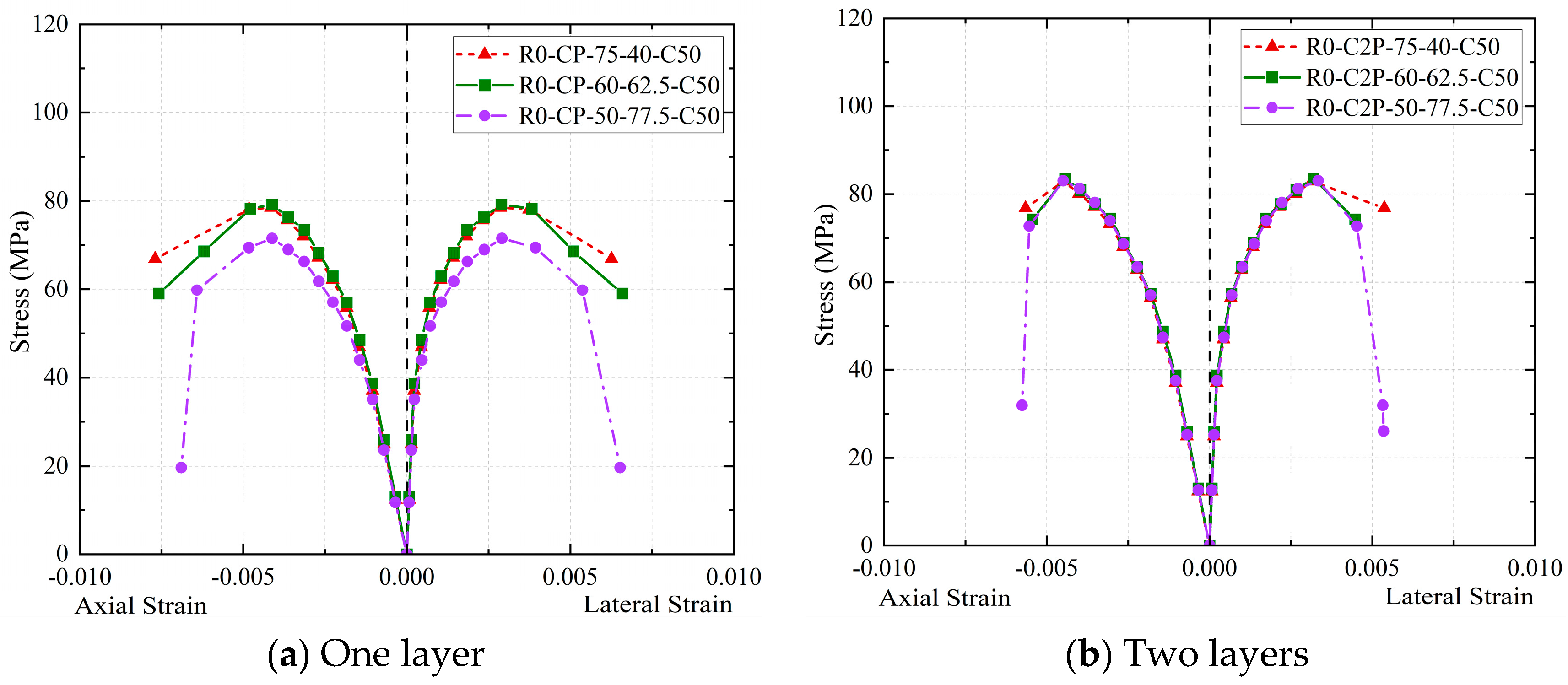
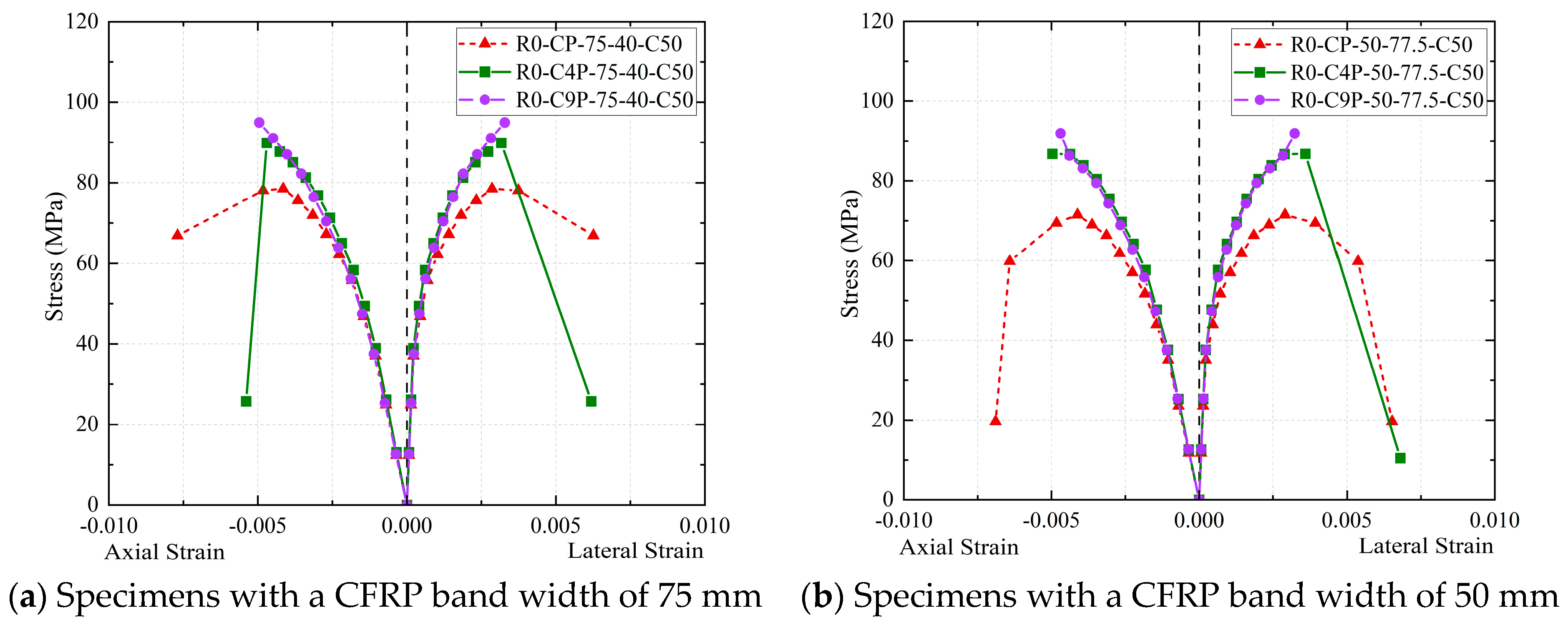
Figure 10) show that when the mid-region lacks CFRP strip confinement of sufficient width or number of layers (e.g., R100-CP-25-45-C50, R100-CP-50-35-C50), premature crushing failure of the concrete occurs in this area. This causes the PVC and unbroken CFRP strips to fail to fully exert their potential confinement capacity, and the specimen exhibits weak confinement characteristics. Conversely, when CFRP strips of sufficient width (e.g., R100-CP-75-40-C50) or increased layers (e.g., R100-C2P-75-40-C50, R100-C3P-75-40-C50) are arranged in the mid-region, the confinement in this area is fully strengthened. This effectively delays the crushing of the core concrete, significantly improving the bearing capacity and deformation capacity of the specimen, which exhibits strong confinement characteristics, even surpassing the ductility of some fully wrapped specimens (
Figure 10). Therefore, the targeted arrangement of CFRP strips in the mid-region is a key strategy for optimizing confinement efficiency and economy.
In addition, the impact of end friction on confinement efficiency is discussed below. Friction generates additional confining pressure at specimen ends (equivalent to 5–10% local pressure enhancement). This explains the slower initial crack development in unconfined specimens (
Figure 7). For CFRP-PVC composite confined specimens, however, the PVC’s plastic deformation capacity absorbs localized stresses from friction, leaving the core confinement mechanism largely unaffected (
Figure 8a). This effect slightly alters failure localization (e.g., conical crushing in plain concrete) but does not compromise the core confinement mechanism [
39].
The above failure mechanism and test phenomena indicate that when CFRP confinement with sufficient strip width exists in the mid-region of the specimen, the combined CFRP–PVC strip confinement mode can most effectively function for the core failure zone. Moreover, due to the progressive nature of CFRP fracture—meaning that after CFRP in the compressed concrete core (specimen mid-region) cracks, the fracture extends towards both ends—the CFRP–PVC can fully exert its confinement action.
