Article

Axial Performances of CFRP-PVC Confined RAC Columns: Experimental and Numerical Study

1
Central South Architectural Design Institute Co., Ltd., Wuhan 430064, China
2
School of Civil Engineering and Architecture, Wuhan Institute of Technology, Wuhan 430073, China
3
School of Civil and Hydraulic Engineering, Huazhong University of Science and Technology, Wuhan 430074, China
*
Author to whom correspondence should be addressed.
Buildings 2025, 15(12), 2089; https://doi.org/10.3390/buildings15122089
Submission received: 25 April 2025 / Revised: 13 June 2025 / Accepted: 14 June 2025 / Published: 17 June 2025

Abstract

The use of recycled aggregate concrete (RAC) in construction mitigates environmental pollution by repurposing demolition waste, but its lower compressive strength compared to natural aggregate concrete (NAC) limits broader application. Although carbon fiber reinforced polymer (CFRP) composites and polyvinyl chloride (PVC) tubes have individually been shown to improve concrete strength and ductility, existing studies focus on fully wrapped CFRP jackets on NAC columns and do not systematically explore CFRP–PVC hybrid confinement using strips on RAC. To address this research gap, this study investigates the axial compressive behavior of CFRP–PVC–RAC columns by varying CFRP strip width (from 25 to 75 mm), strip spacing (from 31 to 77.5 mm), and the number of CFRP layers (one to nine) over a central PVC tube. Axial compression tests reveal that specimens with a central CFRP strip width equal to or greater than 75 mm achieve peak loads up to 1331 kN and that, after rupture of the central strip, the remaining strips continue to carry load, producing a more gradual stress–strain decline and enhanced ductility compared to fully wrapped controls (peak load 1219 kN). These results show that CFRP–PVC composites enhance the axial compressive strength and ductility of RAC columns. The confinement mechanism increases the ultimate axial strain and redistributes transverse stresses, delaying brittle failure and improving deformation capacity. When two or more CFRP layers are applied, strip width and spacing affect axial stress by no more than three percent. Increasing layers from one to four raises axial strength by approximately 23 percent, whereas adding layers beyond four yields diminishing returns, with less than a six percent increase. Finally, a multilayer lateral confined pressure formula is derived and validated against thirty-two specimens, exhibiting errors no greater than three percent and accurately predicting effective confinement. These findings offer practical guidance for optimizing strip dimensions and layering in CFRP–PVC reinforcement of RAC columns, achieving material savings without compromising performance.

1. Introduction

With the development of social economies, the quantity of engineering construction is increasing, and the amount of concrete used as one of the most commonly used materials in engineering construction is also increasing [1]. The urbanization process produces a large amount of construction and demolition waste (CDW), resulting in environmental pollution problems and processing difficulties. Recycled aggregate concrete (RAC) is an environmentally friendly concrete in which some or all of the natural aggregate (NA) is replaced by recycled aggregate (RA). The full utilization of RAC can not only alleviate the disposal problem of CDW but also reduce the consumption of natural resources [2,3]. However, traditional RA has not been widely used in engineering fields because of its low strength and high processing cost. To compensate for RAC’s brittleness, confining RAC with fiber products is an effective way to improve its mechanical properties. Fiber reinforced polymer (FRP) composites, such as glass fiber reinforced polymer (GFRP), carbon fiber reinforced polymer (CFRP), basalt fiber reinforced polymer (BFRP), and steel fiber, have been widely employed to improve the strength and ductility of natural aggregate concrete (NAC) [3]. It has also been widely used in maintenance and reinforcement projects [4,5,6,7,8,9,10].
Existing studies show that CFRP can significantly improve the bearing capacity and deformation capacity of concrete members [11,12,13,14,15,16]. Carbon fiber has good bonding performance with concrete [17]. Its density is 25% that of steel, but its tensile strength is 7 times that of steel. It is lightweight, has high strength, and is easy to be constructed. It has been proven in engineering practice that the bearing capacity of concrete beams and columns can be improved to a certain extent after CFRP wrapping. Liang [18] used CFRP to construct the constrained shell and studied the influence of the number of CFRP wrapping layers and the strength grade of concrete on the bearing capacity of CFRP-constrained concrete specimens. Compared with traditional building materials, the cost of CFRP is too high, so it is obviously uneconomical to use fully wrapped CFRP for components that can meet the seismic requirements only by slightly increasing the bearing capacity. In this regard, Saadatmanesh [19] proposed the idea that CFRP bands constrain concrete in sections. Xie [20] used CFRP bands with different widths, spacing, thicknesses, and layers to constrain standard concrete cylinder specimens, and studied the influence of the above parameters on compressive strength. Shitindi [21] analyzed the test results of using FRP spirals to strengthen concrete. The results show that its performance is similar to that of steel screw-fixed concrete, but the effect of improving the bearing capacity is not great.
In order to solve the corrosion resistance problem of concrete, Kurt [22] first proposed the concept of PVC tube restraint concrete. It is proven that PVC tube restraints in concrete can improve the ductility of core concrete. With the development of FRP materials, FRP-PVC composite materials combining FRP and PVC tubes have begun to be investigated. Toutanji and Saafi [23,24,25] studied the mechanical properties and durability of FRP-PVC tube concrete short columns. Yu [26] carried out a series of axial compression, bias compression, and durability tests on CFRP-PVC tube constrained concrete, mainly considering the influence of strip spacing, axial reinforcement, and slenderness ratio on the mechanical properties of CFRP-PVC tube constrained concrete. Jiang [27] studied the mechanical properties of medium-length concrete columns with four different slenderness ratios constrained by CFRP-PVC tube under axial compression, and deduced the calculation formula for bearing capacity. Li [28] conducted axial compression test research on BFRP-PVC tube constrained RAC. The experimental results show that the binding effect of the BFRP-PVC tube can obviously improve the strength and ultimate strain of RAC, and there is no significant size effect on the specimen constrained by the BFRP-PVC tube. Feng [29] and Fang [30] investigated the influence of the joint restraint of PVC and FRP on the axial compression performance of short concrete columns through a mathematical model. Gao [31] and Fang [32] respectively conducted experiments on constraining short concrete columns by PVC-PFRP and CFRP–PVC, and demonstrated that the mechanical properties, such as axial compression, shear resistance, and ductility of short concrete columns under the synergistic action of PVC and FRP, are significantly improved compared with those of short concrete columns constrained only by FRP. Building upon these foundations, recent research has employed sophisticated finite element analysis and machine learning to investigate CFRP-PVC confined concrete under diverse conditions, significantly deepening the mechanistic understanding [33]. Studies have rigorously quantified the axial stress–strain behavior and confinement efficacy for novel core materials, including coral seawater and sea–sand concrete [34] and spontaneous combustion gangue concrete [35]. The system’s application has been extended to complex structural forms, such as CFRP-PVC tube composite with internal I-shaped steel sections [36] and square cross-sections [37], with numerical models developed to analyze their axial compression mechanisms and predict bearing capacity. Moreover, advanced computational approaches have been successfully applied to model the complex behavior of CFRP-PVC confined concrete under uniaxial eccentric compression [38]. However, the investigations into CFRP–PVC strip-confined recycled aggregate concrete columns remain limited, with existing studies often constrained by narrow parameter variations and oversimplified design variables. Critical gaps persist in understanding the synergistic effects of strip geometry, localized layering configurations, and multi-variable interactions under axial compression.
To address these limitations, this study systematically explores the mechanical behavior of hybrid CFRP–PVC strip-confined RAC columns, incorporating diverse strip dimensions, spacing, layered confinement strategies, and recycled aggregate substitution levels. The model for lateral confinement pressure is developed to quantify the influence of multi-layered CFRP strips, complemented by finite element validation. The findings advance the optimization of sustainable composite confinement systems, offering practical insights for enhancing the axial performance of RAC structures.
Figure 1 illustrates the flowchart of the method and the proposed validation in this work.

2. Experimental Program

2.1. Test Materials

2.1.1. Concrete

In this test, the plain concrete with a matrix strength of C50 and the raw materials of the RAC specimen are provided by China Construction Commercial Concrete Co., Ltd., and manually prepared by the laboratory. The specimen template is made of PVC tube with an inner diameter of 152 mm, a height of 305 mm, and a thickness of 4 mm (Figure 2). While pouring the concrete specimens, three groups of cube test blocks with a size of 150 mm × 150 mm × 300 mm are left for each concrete specimen of matrix strength, and the test blocks and the concrete specimens completed by pouring are cured at the same time. The mix ratios of RAC columns with different replacement rates are shown in Table 1, where R100-C50 represents a core concrete strength of C50 and an RA replacement rate of 100%.

2.1.2. Carbon Fiber Cloth

The carbon fiber cloth used is CFS-I-300G, produced by Beijing Carbon Engineering Research Institute Co., Ltd. Its performance indexes are shown in Table 2.

2.1.3. Carbon Fiber Cloth Impregnating Glue

The selected carbon fiber cloth impregnating glue is a supporting product for carbon fiber cloth, which is divided into A glue and B glue. At the same time, two glues are prepared according to the ratio A:B = 2:1 and stirred evenly. The performance indexes are shown in Table 3.

2.2. Specimen Design

The cross-sectional shape of the specimen selected for this test is circular, and its size is 152 mm (diameter) × 305 mm (height). The strengthening and winding methods of carbon fiber cloth are integrated wrapping and strip wrapping, respectively. The integrated wrapping method can be divided into only CFRP wrapping and CFRP-PVC combined wrapping. All the strip wrapping methods are CFRP-PVC combined wrapping, and the number of PVC wrapping layers is one. The specimens wrapped by CFRP strips are shown in Figure 3. CFRP strips come in widths of 25, 35, 50, and 75 mm, respectively. The strip spacing for each of these widths is 31, 35, 40, 45, 55, and 77.5 mm, respectively. For the specimens with a CFRP strip width of 75 mm and a distance of 40 mm, the number of central CFRP strip layers is one, two, and three, and the number of central CFRP strips for all other specimens is one. The RA substitution rate for all strip wrapping specimens is 100%. For the specimens with no confinement and an integrated wrapping method, the RA substitution rates for the specimens are 0% and 100%, respectively. In order to more intuitively reflect the advantages of PVC, the control group specimens are set as the unreinforced plain concrete specimen and the RAC specimen wrapped with only one layer of CFRP. The finished specimens are shown in Figure 4.
The characteristic parameters of the test piece are shown in Table 4. R100 indicates that the RA substitution rate is 100% for specimen R100-CP-50-77.5-C50. C, P, 50, and 77.5 represent one layer of CFRP strip wrapping, one layer of PVC wrapping, a strip width of 50 mm, and a strip spacing of 77.5 mm, respectively. C50 represents the concrete strength grade of the specimen. In specimen R100-C2P-75-40-C50, C2 represents CFRP strip wrapping, and the number of wrapping layers is two. The CP in specimen R100-CP-C50 means that the CFRP and PVC are wrapped as a whole and that the number of wrapping layers is one. In specimen R100-C-C50, C indicates that the CFRP is integrated and that the number of wrapping layers is one. R100-C50 represents an unconfined C50 RAC column with 100% RA substitution.

2.3. Arrangement of Measuring Points

As illustrated in Figure 5, a pair of strain gauges are arranged at symmetrical positions on the surface of the CFRP strip in the center of the CFRP-PVC-RAC column (a). In addition, a pair of strain gauges are positioned in symmetric places on both sides of the unconfined RAC column’s midsection (see Figure 5b).

2.4. Loading

Based on the Standard for Concrete Structures Test Methods (GB 50152–2012), axial compression tests are carried out on a 3000 kN hydraulic testing machine. To avoid the influence of external factors on the loading process, the specimens need to be preloaded before being loaded. First, the specimens are formally loaded using the load control method at a rate of 3 kN/s. After reaching peak load, the displacement control method is adopted, and the growth rate of the displacement is around 0.0025 mm per minute until the specimens fail. The specimen loads and strains are read directly from the DH3820 high-speed static strain test and analysis system.

3. Results and Discussion

3.1. Failure Modes and Phenomena of Specimens

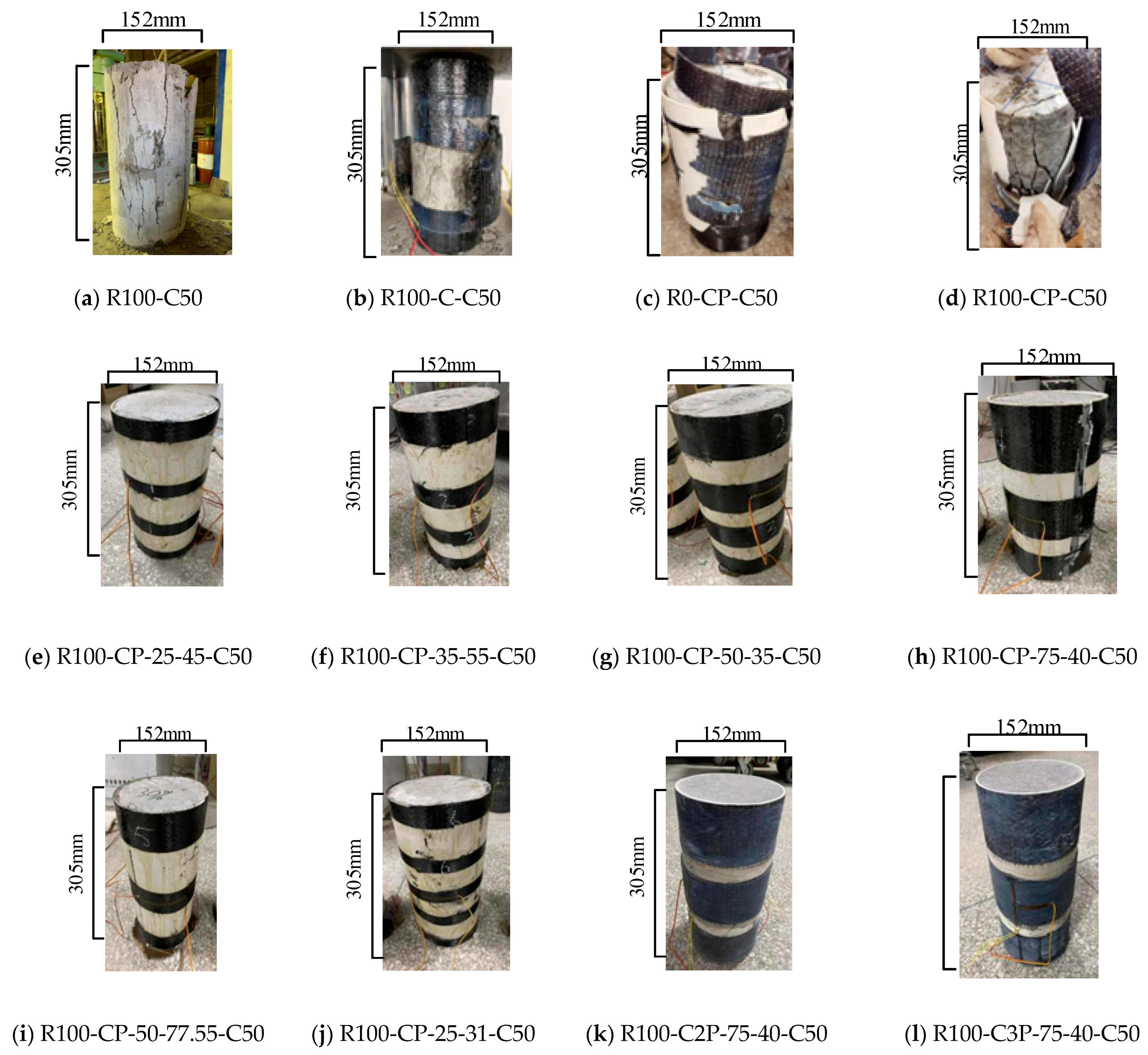
The failure states of different restrained specimens are shown in Figure 6. When the load is increased to 659 kN, small cracks appeared in unconfined specimen R100-C50 (Figure 6a). As the load is increased to the peak value of 843 kN, the crack widens rapidly, the concrete on the surface of the specimen falls off into flakes, and the specimen is destroyed. There is no warning before the failure.
The middle part of specimen R100-C-C50 (Figure 6b) expands laterally and bulges when the load is increased to 1001 kN, and the RAC produces a slight cracking sound. When the load is increased to the peak load of 1213 kN, cracks appear in the middle of the CFRP and rapidly extend vertically to the bottom. As the crack length of the CFRP increases to 100 mm, the specimen fails with the fracture of the CFRP and the slamming of the RAC crushed stone. For specimens R0-CP-C50 and R100-CP-C50 (Figure 6c,d), when the load is increased to 1274 kN and 1219 kN, the middle part of the carbon fiber begins to turn white, and the specimens have no obvious deformation. If the load is further increased to the peak load of 1341 kN and 1411 kN, the CFRP crack occurs in the middle and the crack width is extended to about 300 mm at both ends in a zigzag pattern, which is slower than that of the R100-C-C50 crack. Finally, the PVC and CFRP are destroyed at the same time, and the specimen is broken. It can be seen that CFRP-PVC plays a role in improving the ductility of the specimen.
Specimens R100-CP-25-45-C50 (Figure 6e), R100-CP-35-55-C50 (Figure 6f), R100-CP-50-35-C50 (Figure 6g), and R100-CP-25-31-C50 (Figure 6j) all fail in the same way. With the increase in load, the middle part of the specimen bulges. While the specimen fails, the core concrete cracks, the middle part of the CFRP begins to crack but does not break, and there is no obvious phenomenon of damage to the PVC.
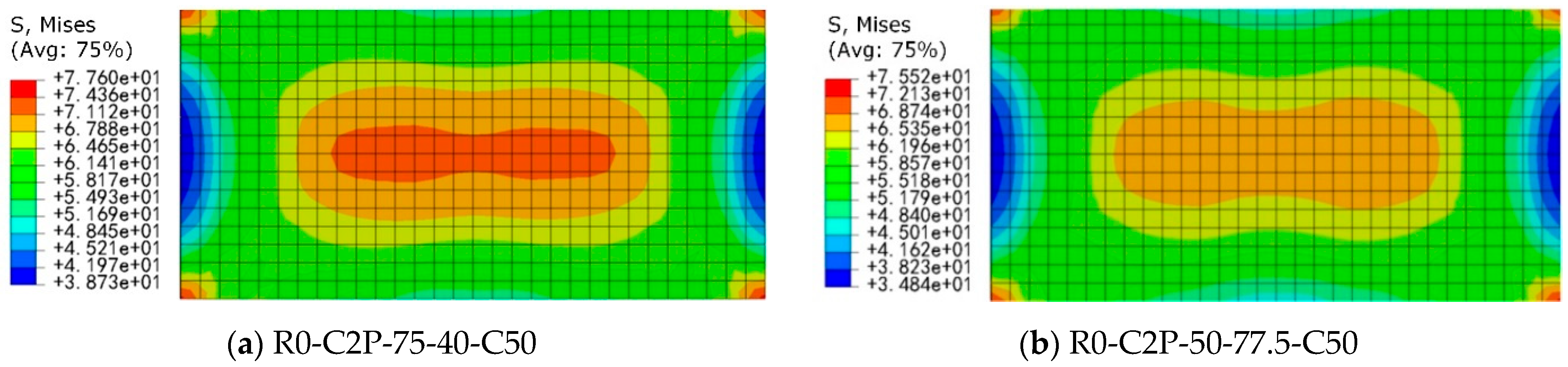
Once the load is increased to 1310 kN, an outer bulge appears in the middle of specimen R100-CP-75-40-C50 (Figure 6h), followed by a small crack of about 3 mm in the middle strip. The CFRP strips at both ends of the specimen do not reach the constraint limit when the load is increased to 1331 kN, and the specimen retains its bearing capacity. Subsequently, the central CFRP strip develops a serrated fracture. While the pressure is increased further, the CFRP strips at both ends crack simultaneously with the PVC, with a cracking length of 305 mm. The specimen is damaged.
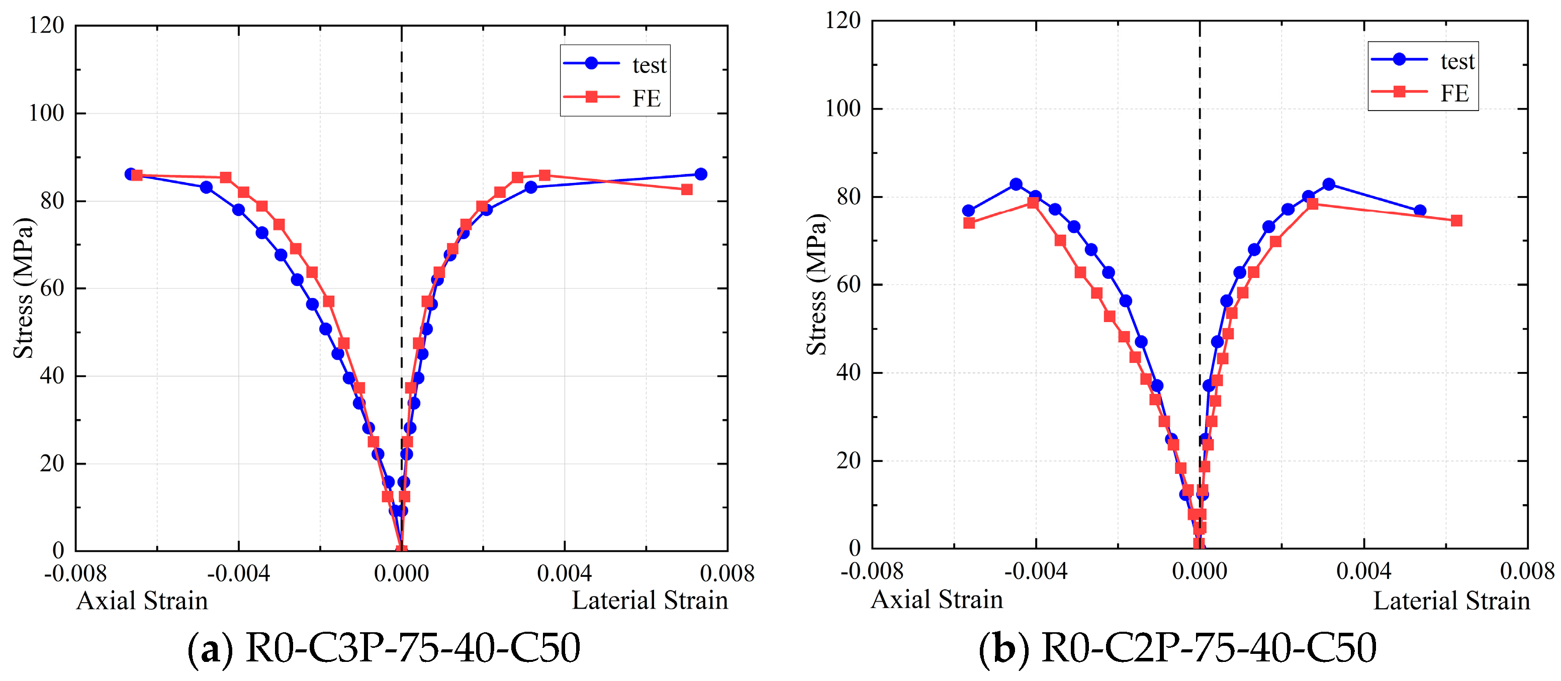
There is no obvious sign of damage on the surface of specimens R100-C2P-75-40-C50 and R100-C2P-75-40-C50, and no trace of damage on the PVC tube and CFRP strips. Because of the increased number of layers of outer CFRP strips in the middle of the RAC column, the central CFRP strips do not fracture, and the failure locations of the specimens are concentrated in the inner RAC. Thus, the CFRP restraint with sufficient strip width in the middle of the specimen can make the CFRP-PVC tube fully exert its restraint effect. Since the CFRP strips are broken one by one from the middle to both ends, the specimens have better ductility.
Furthermore, the friction forces at the specimen ends against the loading plates influence the failure modes. For unconfined specimens (e.g., R100-C50), end friction restrains lateral expansion, inducing localized conical crushing at the end zones (Figure 6a) and delaying vertical crack propagation. In CFRP strip-confined specimens (e.g., R100-CP-75-40-C50), friction enhances the confinement effectiveness of end strips, concentrating cracks within the mid-span strip gap regions. Notably, the low friction coefficient of PVC (μ ≈ 0.1) mitigates end friction effects. Conversely, fully wrapped CFRP specimens (R100-C-C50) exhibit exacerbated CFRP stress concentration due to direct CFRP-plate contact, accelerating CFRP fracture (Figure 6b).

3.2. Axial Stress–Strain Behavior

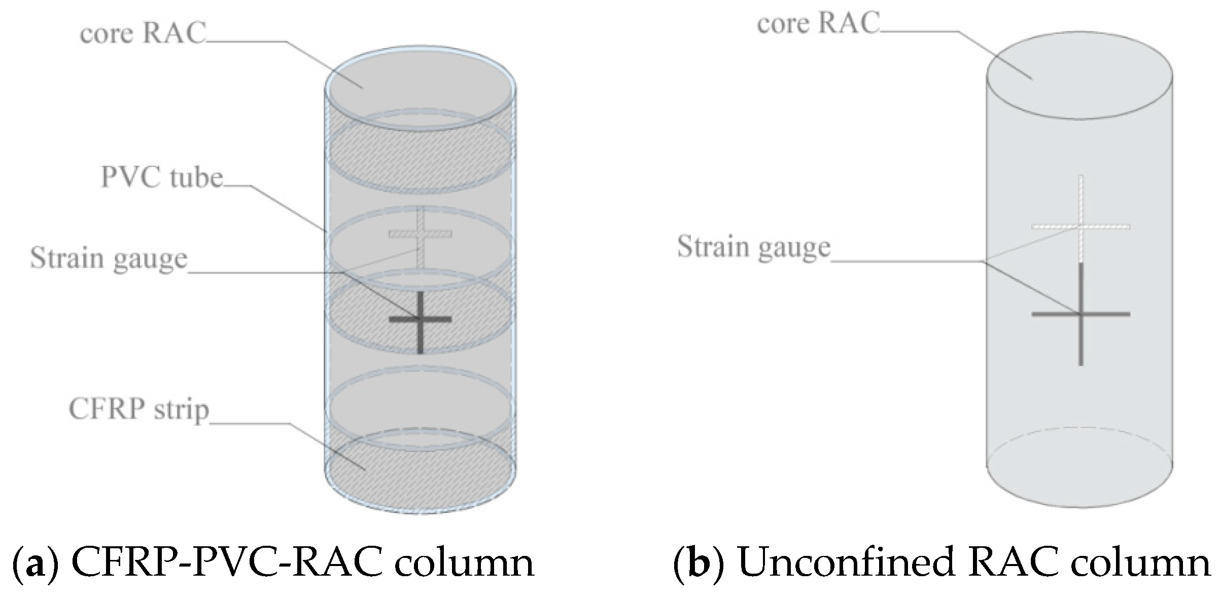
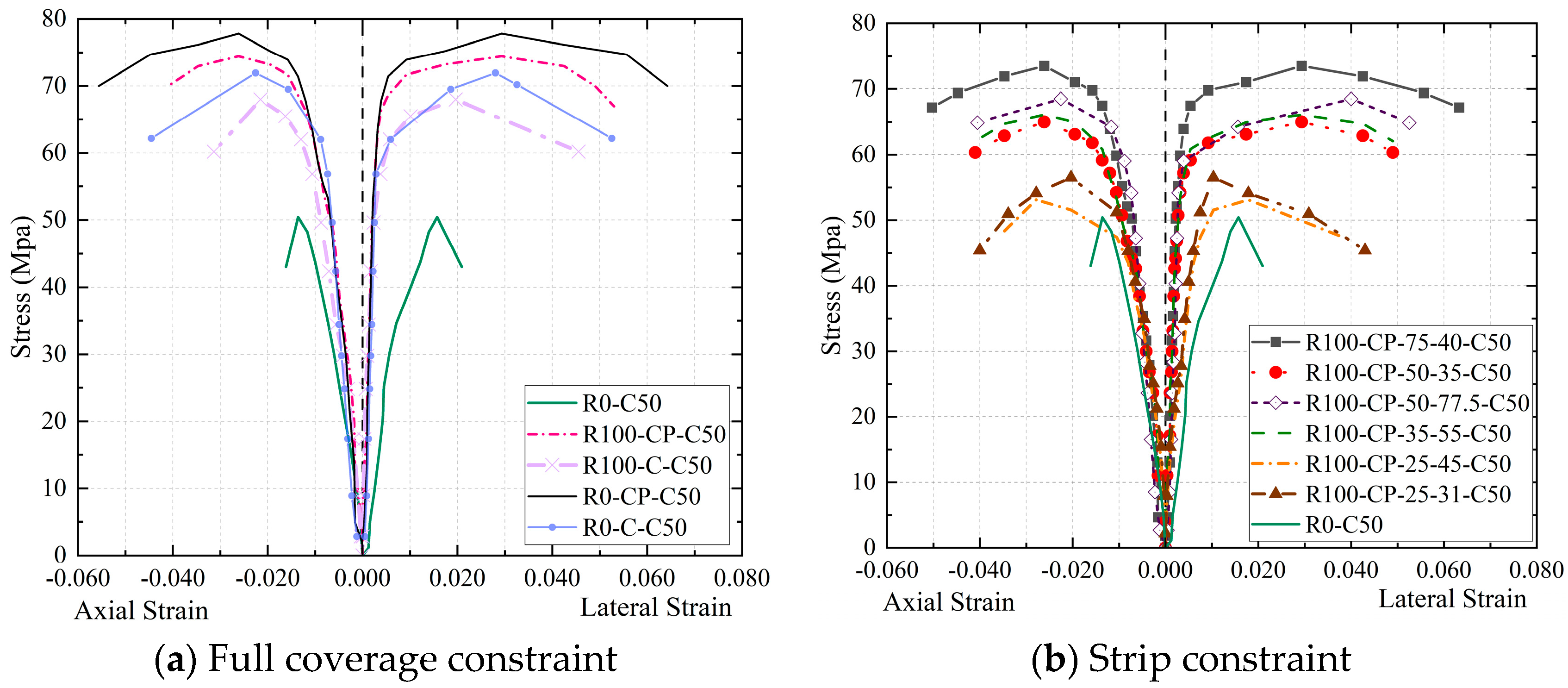
Figure 7 displays the stress–strain curves of specimens under various restrictions. The stress–strain curves of unconfined specimen R0-C50 exhibit typical unconstrained characteristics, including (1) a tiny ascending section slope, (2) almost no reinforcement phase, (3) a steep descent curve, and (4) a fast destruction of the specimen upon reaching the peak load. The compressive performance and deformation capacity of other specimens increase to varying degrees because the PVC and CFRP limit the lateral deformation of the core concrete.
When just the CFRP is constrained, as depicted in Figure 7a, RAC specimen R100-C-C50 with 100% replacement rate performs worse in terms of deformation capacity and compressive strength than NAC specimen R0-C-C50. This is due to the fact that there are numerous microcracks inside the re-fractured RAs and the surface is coated with cement mortar, resulting in large pores, many micro cracks, and high brittleness of RAC. When cracks occur in the RAC column, uneven lateral expansion affects the confining ability of the CFRP directly in contact with the RAC column, resulting in uneven force. The core concrete strength of specimen R0-C-C50 has a greater value. Although its compressive strength is larger than that of other CFRP-PVC joint restraint specimens, the ductility is still not as excellent because as the load grows, cracks emerge inside the core concrete of the joint restraint specimen and the lateral deformation increases. At this time, the joint restraint effect of PVC and CFRP on concrete makes the bearing capacity of the specimen continue to rise. The reasons are as follows: (1) When the PVC is located between core concrete and CFRP cloth, direct contact between the CFRP and the concrete surface is avoided, local stress concentration of carbon fiber caused by uneven transverse expansion of concrete column is reduced, and the strength of the CFRP is fully utilized. Therefore, as the transverse deformation of the core concrete increases, the PVC deforms and absorbs a portion of the energy due to extrusion, leading to a certain load-holding capacity of the specimen. (2) PVC has a certain thickness and stiffness. The constraint stress of CFRP on the concrete column may be uniformly conveyed to the concrete column via PVC, avoiding partial damage of the concrete column in advance. (3) PVC has a particular toroidal tensile strength. It has a restraint effect on the concrete column before the compressive strength of the concrete column reaches the ultimate compressive strength. In addition, the effect of the RA substitution rate on the ductility of the RAC column is reduced under the combined constraints of the PVC and CFRP, and the compressive strength of R100-CP-C50 is slightly lower than that of R0-CP-C50. It can be seen from 
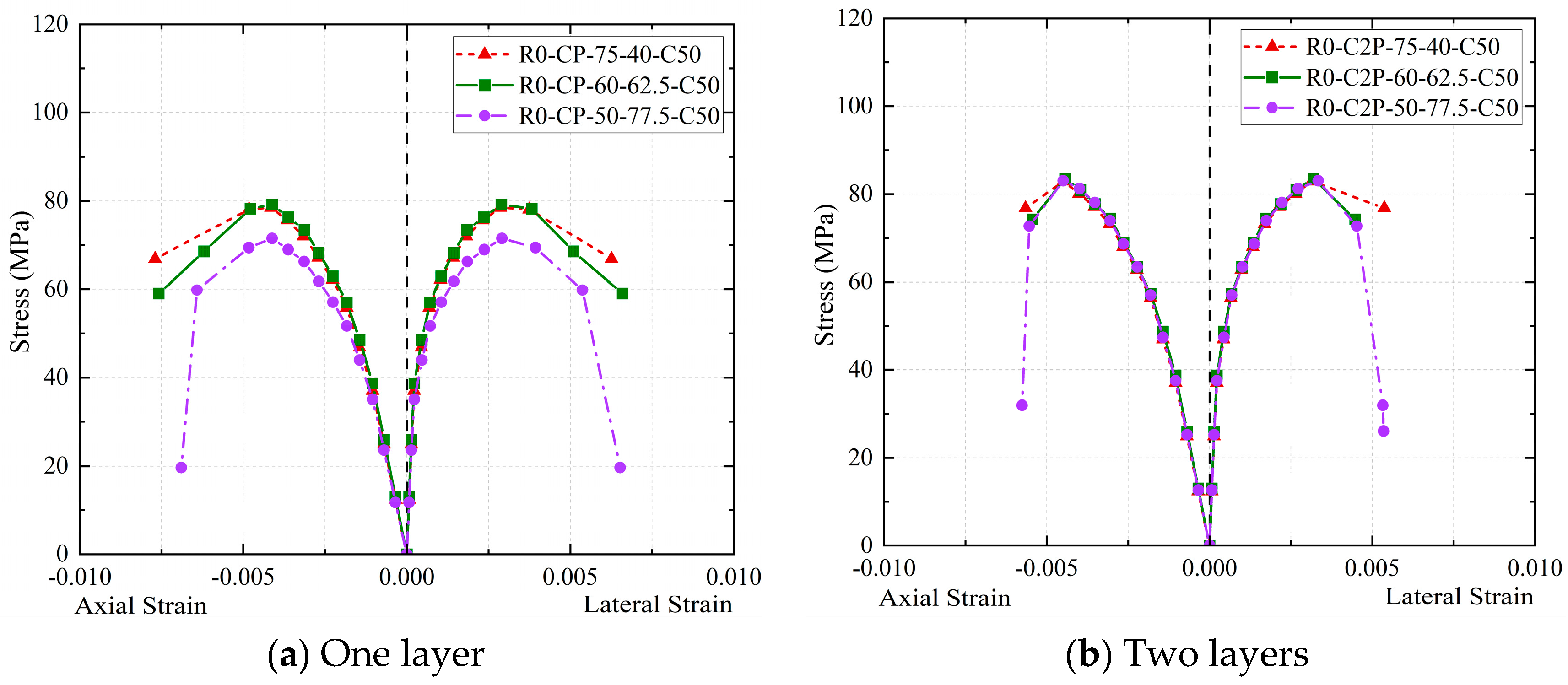
Figure 7b that the strip width and spacing have significant influence on the compressive strength and ductility of the RAC column.
To reflect the characteristics of different strong and weak constraints, Figure 8 depicts the stress–strain curves of the specimens with strong and weak constraints. Specimens R0-CP-C50, R100-CP-C50, R100-CP-75-40-C50, and R100-CP-75-77.5-C50 (Figure 8a) show a typical strong constraint state: the stress rises during the curve strengthening phase, but the specimen retains some load-holding capacity. As shown in Figure 8b, the specimens R0-C-C50, R100-C-C50, R100-CP-25-31-C50, R100-CP-25-45-C50, R100-CP-35-55-C50, and R100-C-50-35-C50 exhibit poor constraints: the curve does not rise clearly in the strengthening stage, and the specimen is softening. When compared to the weakly constrained specimens, strongly constrained specimens have higher compressive strength and ductility. Among the band restraint specimens, R100-CP-75-40-C50 and R100-CP-50-77.5-C50 are strongly restrained specimens. The reason for this is that, in comparison to other band constrained specimens (weakly constrained specimens), CFRP bands of sufficient width are attached to their outer middle.
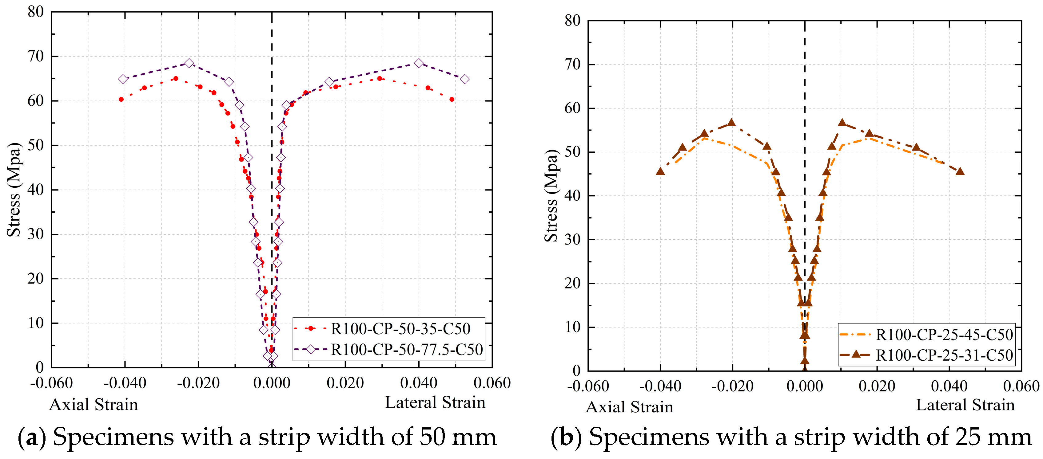
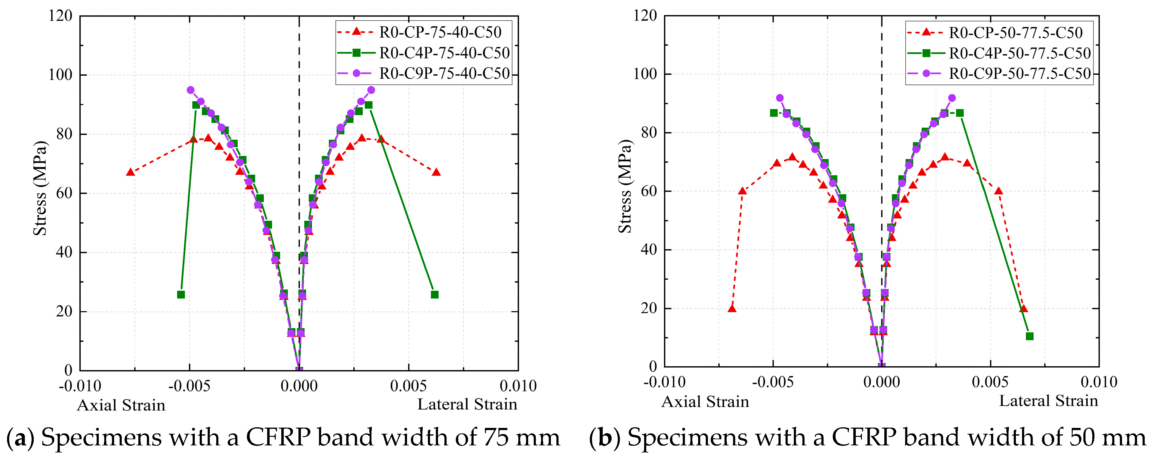
The comparison of the restraint effects of specimens with the same strip width but varying strip spacing is shown in Figure 9. To further explore the above mechanisms, specimens R100-CP-50-77.5-C50 and R100-CP-50-35-C50, with the same strip width, are compared (Figure 9a), and it is found that the bands of specimen R100-CP-50-35-C50 are more densely arranged and more CFRP materials are employed. On the contrary, its compressive strength and ductility are lower than those of R100-CP-50-77.5-C50. This is related to the fact that the core stress area of specimen R100-CP-50-35-C50 is not externally attached with a CFRP band and only constrained by PVC, which causes the middle of the RAC column to be crushed in advance and fail, and the CFRP of the restraint specimen cannot fully implement its restraint effect. As shown in Figure 9b, the load-bearing capacity of specimen R100-CP-25-45-C50 is lower than that of specimen R100-CP-25-31-C50, but the deformation capacity is similar. The axial deformation of the specimens under the constraints of a CFRP strip and PVC pipe presents a continuous “arch” distribution, so the existence of an “arch” may mean part of the load under the axial load is shared, but the total reinforcement effect is not optimum because the strip is too narrow. Therefore, the effect of strip restraint is mainly affected by whether there is a strip constraint in the middle of the specimen and the width of the strip.
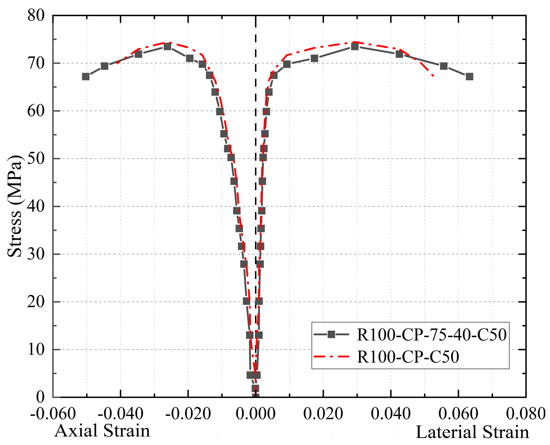
Figure 10 depicts a comparison of the stress–strain curves of the best CFRP strip restraint specimen, R100-CP-75-40-C50, in this experiment with the CFRP full-coverage restraint specimen R100-CP-C50. As can be observed, the bearing capacity of the two types of specimens is almost the same, while the strip constrained specimens have a higher deformation capacity. The reasons are as follows: (1) When the middle CFRP band reaches the constraint limit and breaks in specimen R100-CP-75-40-C50, the upper and lower CFRP bands can continue to work normally, and each CFRP band is unaffected by the other. (2) The binding force on the core concrete is non-uniform in the lateral direction due to the CFRP strip wrapping mode, and the restraint mechanism is different from that of the whole wrapped concrete. To summarize, specimens in the strip restraint mode are more economical and effective than those in the whole restraint mode.
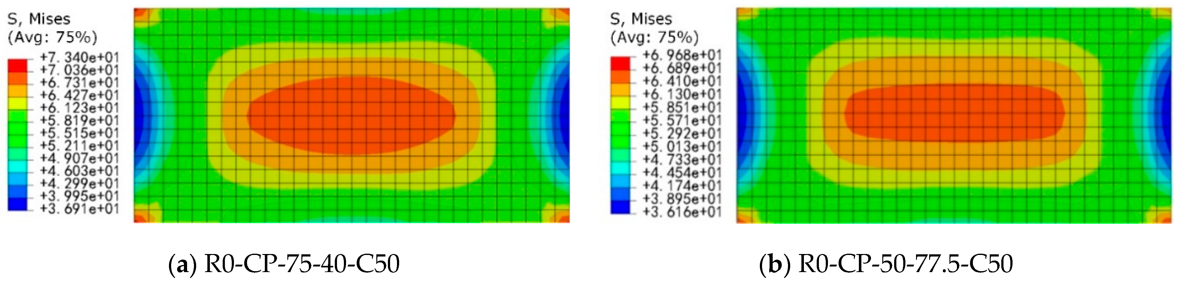
It should be noted that the core role of CFRP strips (or full wrapping) is to provide circumferential confinement, restrict the lateral expansion of concrete, and thereby increase its axial compressive strength and ductility. Based on the above failure mechanism, the mid-region of the specimen is the part with the highest confinement demand and the most significant confinement effect. Therefore, concentrating CFRP strips in the mid-region of the specimen (especially for strip wrapping) can most effectively provide confinement force to the weakest area. The test results (as seen in Figure 6, Figure 8 and Figure 10) show that when the mid-region lacks CFRP strip confinement of sufficient width or number of layers (e.g., R100-CP-25-45-C50, R100-CP-50-35-C50), premature crushing failure of the concrete occurs in this area. This causes the PVC and unbroken CFRP strips to fail to fully exert their potential confinement capacity, and the specimen exhibits weak confinement characteristics. Conversely, when CFRP strips of sufficient width (e.g., R100-CP-75-40-C50) or increased layers (e.g., R100-C2P-75-40-C50, R100-C3P-75-40-C50) are arranged in the mid-region, the confinement in this area is fully strengthened. This effectively delays the crushing of the core concrete, significantly improving the bearing capacity and deformation capacity of the specimen, which exhibits strong confinement characteristics, even surpassing the ductility of some fully wrapped specimens (Figure 10). Therefore, the targeted arrangement of CFRP strips in the mid-region is a key strategy for optimizing confinement efficiency and economy.
In addition, the impact of end friction on confinement efficiency is discussed below. Friction generates additional confining pressure at specimen ends (equivalent to 5–10% local pressure enhancement). This explains the slower initial crack development in unconfined specimens (Figure 7). For CFRP-PVC composite confined specimens, however, the PVC’s plastic deformation capacity absorbs localized stresses from friction, leaving the core confinement mechanism largely unaffected (Figure 8a). This effect slightly alters failure localization (e.g., conical crushing in plain concrete) but does not compromise the core confinement mechanism [39].
The above failure mechanism and test phenomena indicate that when CFRP confinement with sufficient strip width exists in the mid-region of the specimen, the combined CFRP–PVC strip confinement mode can most effectively function for the core failure zone. Moreover, due to the progressive nature of CFRP fracture—meaning that after CFRP in the compressed concrete core (specimen mid-region) cracks, the fracture extends towards both ends—the CFRP–PVC can fully exert its confinement action.

4. The Effect of CFRP Strip Layers

In order to further study the influence of the number of CFRP band layers on the mechanical properties of CFRP-PVC-RAC columns, this work simulates the CFRP-PVC-RAC column test model with a different number of band layers (1–9 layers of CFRP bands attached outside the core compression zone) by finite element (FE) software (Abaqus 6.14).

4.1. Establishment of Model

To better reflect the properties of concrete, this work uses the concrete damage plastic (CDP) model of compression failure and tensile cracking. The basic parameters of CDP are shown in Table 5.
CFRP cloth is an anisotropic material that exhibits different properties in each direction under external force, and is directly pulled apart when its ultimate strength is reached. The basic damage parameters of the CFRP are displayed in Table 6. In this study, the discrete model is used to define the material direction, which can effectively simulate the constrained situation of CFRP cloth. The engineering constants of the CFRP elastic modulus are shown in Table 7, where E is the elastic modulus of the CFRP, N is Poisson’s ratio, and G is the shear modulus of the CFRP.

4.2. Correctness Verification of Finite Element Model

The reliability of the FE model is verified by the stress–strain curve comparison between the FE results and the test results, as shown in Figure 11. The stress–strain curves of the FE simulation results and the test results fit well, which indicates that the FE simulation of axial compression test results in this study has reference value. Therefore, this FE model is used to simulate the axial compression tests of CFRP-PVC-RAC columns with multilayer CFRP strips in the middle.

4.3. Stress–Strain Curve Analysis of Concrete Columns with Different Numbers of Strip Layers

Due to space limitation, only the stress–strain curves of specimens with one, two, four, and nine layers of CFRP strips attached to the middle are shown in Figure 12. When one layer of CFRP band is attached to the middle of the concrete, the stress–strain difference between specimen R0-CP-75-40-C50 and specimen R0-CP-60-62.5-C50 is small, while the axial compressive stress of specimen R0-CP-50-77.5-C50, with a strip width of 50 mm, is significantly lower than that of the former two. This is caused by the fact that, when one layer of CFRP strip is pasted outside, the 50 mm width of the strip is insufficient to cover the concrete core compression zone, resulting in insufficient lateral restraints supplied by CFRP-PVC (Figure 13).
When the number of CFRP band layers in the middle of the concrete exceeds two, the band width and band spacing have little influence on the stress–strain of the concrete columns. The reason is that the strip not only increases the restraint ability of the middle part of the concrete structure but also limits its deformation ability. The position of the core compression zone is gradually transferred from the middle to the position of the strip spacing at both ends. From the stress nephogram of the concrete in Figure 14, it can clearly be seen that with the increase in the number of outer CFRP strip layers in the middle of the structure, the influence of strip width on the axial compression performance of the structure gradually decreases.
As shown in Figure 15, with the increase in the number of band layers in the core compression zone, the structural stress increases and the strain decreases. This may be associated with the fact that increasing the number of CFRP band layers not only improves the confining ability of CFRP-PVC but also limits the deformation ability of the structure’s core compression zone. When the number of CFRP strip layers does not exceed four, it has a great influence on the stress and strain of the concrete. The axial compressive stresses of specimen R0-C4P-75-40-C50 and specimen R0-C4P-50-77.5-C50 increase by 23% and 24% compared with specimen R0-CP-75-40-C50 and specimen R0-CP-50-77.5-C50, respectively. However, the axial compressive stresses of these specimens increase by only 7% and 5%, respectively, when the nine-layer band is attached to the outer surface compared with the four-layer band.

5. The Lateral Confining Pressure of CFRP-PVC on RAC

5.1. Derivation of Formulas

This work proposes a calculation formula to predict the effective lateral confining pressure of a CFRP-PVC-RAC column with multiple layers of CFRP strips attached to the middle part (core compression zone). Externally bonded PVC-FRP composite jacketing induces triaxial compression in the core concrete of strengthened structural elements. This confinement mechanism significantly enhances both the compressive strength and the deformability of the concrete. The composite action of the FRP and PVC layers collectively generates lateral confinement pressure on the concrete core [31], as schematically represented in Figure 16. Here, f l is the total lateral confinement pressure exerted on the core concrete by the PVC-FRP composite system, f l f is the lateral confinement pressure contribution attributable to the CFRP layer, f l p is the lateral confinement pressure contribution attributable to the PVC layer (within the PVC-FRP composite), E f r p is the elastic modulus of the CFRP, E p v c is the elastic modulus of the PVC, ε f r p is the tensile strain developed in the CFRP under confinement, ε p v c is the tensile strain developed in the PVC under confinement, t f r p is the nominal thickness of the CFRP laminate, and t p v c is the nominal thickness of the PVC layer.
The mechanical properties of the RAC column with multi-layer CFRP strips attached to the core compression zone are shown in Figure 17. The first layer is reinforced with the overall strip, and the other layers are only reinforced with the middle strip. Based on the mechanical equilibrium relationship, the lateral confining pressure f l of CFRP-PVC on the core concrete can be expressed as:
f l = f l f 1 + f l f 2 + f l f x + f l p
where f l f 1 , f l f 2 , and f l f x are the lateral confining pressures provided by the first layer, the second layer, and the x layer ( x 2 ) CFRP strips on the core concrete, respectively, and f l p is the lateral confining pressure provided by the PVC tube.
Based on the force equilibrium of the cross-section, f l f 1 can be described as [31]:
f l f 1 = k e 1 2 n b f r p E f r p ε f r p t f r p H d + 2 t p v c
k e 1 = d H m s 2 t p v c 2 2 d H
Since only the central CFRP band is attached externally starting from the second layer, f l f x is defined as ( x = 2 , 3 , ):
f l f x = k e x 2 b f r p E f r p ε f r p t f r p H d + 2 t p v c
k e x = d H 4 s 2 t p v c x 1 t f r p 2 2 d H
f l p can be represented as:
f l p = 2 E p v c ε p v c t p v c d
where k e 1 and k e x are the effective lateral confining pressure coefficients of the CFRP bands in the first and x layers, respectively; n is the number of CFRP bands in the first layer; m is the number of unconstrained regions under the action of the first layer of CFRP bands; b f r p , E f r p , ε f r p , and t f r p are the width, elastic modulus, tensile strain, and thickness of the CFRP bands, respectively; E p v c , ε p v c , and t p v c are the elastic modulus, tensile strain, and thickness of the PVC pipe, respectively; H is the height of the RAC column; d is the diameter of the core concrete section; and s is the spacing of the CFRP bands.
The effective lateral confining pressure f l f provided by all CFRP bands can be expressed as:
f l f = k e 2 b f r p E f r p ε f r p t f r p H d + 2 t p v c
k e = n k e 1 + k e 2 + k e x
where k e is the effective lateral confining pressure coefficient of multilayer CFRP bands.
In conclusion, Equation (1) can be written as:
f l = k e 2 b f r p E f r p ε f r p t f r p H d + 2 t p v c + 2 E p v c ε p v c t p v c d
Based on the equations and the FEM analysis results above, it can be inferred that:
(1)
The more layers x of CFRP strips in the middle of the concrete column, the greater lateral confining pressure f l , and the influence of x on f l is the most significant.
(2)
The greater the CFRP band width b f r p , the larger the f l . However, with an increase in x , the influence of b f r p on f l gradually decreases. Therefore, it is more economical and effective to increase the number of CFRP strip layers in the middle of the concrete than the strip width.
(3)
The greater the CFRP band spacing s , the smaller the f l , but the effect on f l is small.

5.2. Verification of Formulas

In general, the ultimate stress is related to the elastic modulus of the restraining material and the core concrete. The elastic modulus of the core concrete E c is proportional to the square root of the compressive strength f c o [40]. To verify the accuracy of Equation (9) and better explore the relationship between the ultimate stress and the elastic modulus, the eigenvalue λ [31] is used in Equation (10):
λ = E l f c o
where f c o is the compressive strength of the unconfined RAC column, and E l is the effective lateral confining stiffness of CFRP-PVC, which is related to the effective lateral confining pressure f l . According to Equation (9), it can be expressed as:
E l = k e 2 b f r p E f r p t f r p H d + 2 t p v c + 2 E p v c t p v c d
The compressive strength f c c of the CFRP-PVC-RAC column can be calculated as [31]:
f c c f c o = 1 + k λ f c o α
where α and k are the fitting coefficients. Through regression analysis and iterative computations of the FE analysis results, the fitting curve can be obtained, and the fitting coefficients (here, α = 0.28 and k = 0.56 ) are determined, as shown in Figure 18. Thus, Equation (12) in this work can be rewritten as Equation (13):
f c c f c o = 1 + 0.56 λ f c o 0.28
Based on Equation (13), the strength comparison between the test data ( f c u ) and the prediction values ( f c c ) are shown in Table 8. It can be seen that Equation (9), in which the calculation error is less than 3%, has a high accuracy and a certain reference value. It should be noted that Equation (13) is calibrated using short concrete columns (152 × 305 mm) with CFRP-PVC confinement (strip widths of 50–75 mm, spacings of 40–77.5 mm, up to 9 layers), assuming perfect bond and axial compression at room temperature. Consequently, it provides a reasonable prediction for CFRP-PVC-RAC columns only when those exact material grades, dimensions, confinement details, loading modes, and environmental conditions are met. Its reliability diminishes for configurations beyond these ranges or for RAC with varying recycled-aggregate replacement ratios that are not fully integrated into the model, or for full-scale structures. Therefore, further experimental validation covering wider parameters, recycled-aggregate influences, and full-scale tests is recommended for broader application.

6. Conclusions

This work investigates the effects of strip width, strip spacing, and strip layers of CFRP on the axial compressive properties of CFRP-PVC-RAC specimens. Axial compression tests are carried out to study the failure modes, bearing capacity, and stress–strain curves of each CFRP-PVC-RAC specimen, and the effects of strip spacing and strip width on the specimens’ mechanical properties are discussed. An FE simulation model is established to simulate axial compression tests of the specimens with one to nine layers of CFRP strips in the middle to explore the influence of the number of layers of CFRP strips. Based on the FE simulation and axial compression tests, the lateral confining pressure formula of a CFRP-PVC-RAC column is deduced and verified to guide the design of RAC columns. The following conclusions are drawn:
(1)
When CFRP strips (single-layer thickness: 0.167 mm) are externally bonded to the mid-height core region of RAC columns with a minimum strip width of 75 mm, the CFRP can fully develop its confinement effect. In this case, the specimen reaches a peak load of 1331 kN. Furthermore, after rupture of the central CFRP strips, the remaining upper and lower strips (cross-sectional area: 75 mm × 0.167 mm = 12.5 mm2 per layer) continues to function, resulting in a stress–strain response that declines more gradually than that of a fully wrapped specimen, thereby exhibiting markedly improved ductility.
(2)
For concrete columns in which two or more layers of CFRP strips are applied at mid-height, the strip width has only a minor influence on the axial stress–strain behavior. When the number of CFRP layers is more than 2, the difference in axial compressive stress between specimens with 50 mm and 75 mm strip widths is less than 3% (for example, specimen C4P-75-40-C50 achieves 89.88 MPa, whereas C4P-50-77.5-C50 attains 86.72 MPa). This is attributed to the fact that total CFRP cross-sectional area governs confinement efficacy more than individual width.
(3)
When the number of CFRP layers in the core zone does not exceed four, increasing the layer count significantly enhances axial compression performance. Specimen C4P-75-40-C50 (50.1 mm2 total cross-section) exhibits a 23% higher axial stress capacity compared to single-layer specimen CP-75-40-C50 (12.5 mm2 total cross-section). However, beyond four layers, further improvement becomes marginal: specimen C9P-75-40-C50 (112.5 mm2 total cross-section) shows only a 5.8% increase over C4P-75-40-C50. Therefore, for practical engineering applications, it is recommended to limit the number of CFRP layers in the core region to four or fewer.
(4)
The derived lateral confining pressure equation indicates that the number of CFRP layers has the most significant effect on the lateral confining pressure, followed by the strip width, while the strip spacing has the least influence. Validation against thirty-two test data points shows that the calculated value deviates by no more than 3%. For instance, for specimen C9P-75-40-C50, the measured confined pressure is 94.06 MPa versus a calculated value of 95.05 MPa, demonstrating high reliability.
Overall, the configuration of CFRP strip layers in CFRP–PVC confined short concrete columns can be investigated in the future. Specifically, some studies should be conducted to explore the effects of independently or simultaneously varying the number of strip layers in both the middle and end regions to uncover deeper underlying mechanisms. Meanwhile, given that the current study employs a limited range of strip widths and spacings, with large intervals between parameter values, the selection of strip width and strip spacing parameters can be further studied in detail.

Author Contributions

Conceptualization, Z.H. and Q.W.; methodology, Q.W.; software, R.C.; validation, Z.H., R.C. and Q.W.; formal analysis, Z.H. and R.C.; investigation, Q.W.; resources, Z.H.; data curation, R.C. and J.L.; writing—original draft preparation, Z.H. and C.Z.; writing—review and editing, C.Z. and J.L.; visualization, J.L.; supervision, X.C.; project administration, Z.H.; funding acquisition, Q.W. All authors have read and agreed to the published version of the manuscript.

Funding

This research was funded by the National Natural Science Foundation of China (NSFC, grant No. 52078395 and No. 52478319), the Natural Science Foundation of Hubei province for Distinguished Young Scholars (grant No. 2023AFA103), and the Young Topnotch Talent Cultivation Program of Hubei Province and Central South Architectural Design Institute Co., Ltd. (grant No. CSADI-2022-03).

Data Availability Statement

Data will be made available on request.

Conflicts of Interest

Author Zidong Hu was employed by the company Central South Architectural Design Institute Co., Ltd. The remaining authors declare that the research was conducted in the absence of any commercial or financial relationships that could be construed as a potential conflict of interest.

References

  1. Feng, P.; Wang, J.; Zhang, X.; Ye, L.P.; Yue, Q.R. Development and innovation of combined application of FRP and sea sand concrete. Fiberglass/Compos. Mater. 2014, 12, 13–18. [Google Scholar]
  2. Ghisellini, P.; Ji, X.; Liu, G.; Ulgiati, S. Evaluating the transition towards cleaner production in the construction and demolition sector of China: A review. J. Clean. Prod. 2018, 195, 418–434. [Google Scholar] [CrossRef]
  3. Nežerka, V.; Hrbek, V.; Prošek, Z.; Somr, M.; Tesárek, P.; Fládr, J. Micromechanical characterization and modelling of cement pastes containing waste marble power. J. Clean. Prod. 2018, 195, 1081–1090. [Google Scholar] [CrossRef]
  4. Xu, F.; Chen, J.; Jin, W.L. Experimental investigation of thin-walled concrete-filled steel tube columns with reinforced lattice angle. Thin-Walled Struct. 2014, 84, 59–67. [Google Scholar] [CrossRef]
  5. Kim, D.W.; Shim, C.S. Experiments on flexural strength on composite modular bridge pier cap for CFT columns. KSCE J. Civ. Eng. 2016, 20, 2483–2491. [Google Scholar] [CrossRef]
  6. Han, L.H.; Hou, C.; Wang, Q.L. Square concrete filled steel tubular (CFST) members under loading and chloride corrosion: Experiments. J. Constr. Steel Res. 2012, 71, 11–25. [Google Scholar] [CrossRef]
  7. Park, T.; Hwang, W.-S.; Leon, R.T.; Hu, J.W. Damage evaluation of composite-special moment frames with concrete-filled tube columns under strong seismic loads. KSCE J. Civ. Eng. 2011, 15, 1381–1394. [Google Scholar] [CrossRef]
  8. Yu, F.; Zhou, H.; Jiang, N.; Fang, Y.; Song, J.; Feng, C.; Guan, Y. Flexural experiment and capacity investigation of CFRP repaired RC beams under heavy pre-damaged level. Constr. Build. Mater. 2020, 230, 117030. [Google Scholar] [CrossRef]
  9. Long, Y.-L.; Li, W.-T.; Dai, J.-G.; Gardner, L. Experimental study of concrete-filled CHS stub columns with inner FRP tubes. Thin-Walled Struct. 2018, 122, 606–621. [Google Scholar] [CrossRef]
  10. Wang, Z.; Feng, P.; Zhao, Y.; Yu, T. FRP-confined concrete core-encased rebar for RC columns: Concept and axial compressive behavior. Compos. Struct. 2019, 222, 110915. [Google Scholar] [CrossRef]
  11. Pi, T.; Chen, Y.; He, K.; Han, S.; Wan, J. Study on circular CFST stub columns with double inner square steel tubes. Thin-Walled Struct. 2019, 140, 195–208. [Google Scholar] [CrossRef]
  12. Mao, W.J.; Wang, W.D.; Xian, W. Numerical analysis on fire performance of steel-reinforced concrete-filled steel tubular columns with square cross-section. Structures 2020, 28, 1–16. [Google Scholar] [CrossRef]
  13. Yu, F.; Xu, G.; Niu, D.; Cheng, A.; Wu, P.; Kong, Z. Experimental study on CFRP–PVC confined concrete columns under low cyclic loading. Constr. Build. Mater. 2018, 177, 287–302. [Google Scholar] [CrossRef]
  14. Feng, P.; Cheng, S.; Bai, Y.; Ye, L. Mechanical behavior of concrete-filled square steel tube with FRP-confined concrete core subjected to axial compression. Compos. Struct. 2015, 123, 312–324. [Google Scholar] [CrossRef]
  15. Cai, B.; Wu, A.S.; Zhao, L.L. Reliability of bearing capacity of carbon fiber reinforced columns with large eccentric compression. Concrete 2018, 2, 9–12. [Google Scholar]
  16. Feng, P.; Cheng, S.; Yu, T. Seismic performance of hybrid columns of concrete-filled square steel tube with FRP confined concrete core. J. Compos. Constr. 2018, 22, 04018015. [Google Scholar] [CrossRef]
  17. Xu, R.T. Study on Mechanical Properties of CFRP-PVC Spiral Reinforcement Composite Constrained Self-Compacting Concrete; Guangxi University: Nanning, China, 2021. [Google Scholar]
  18. Liang, J.B.; Yu, H.Q.; Zhu, J.; Long, Y.L. Research on Axial compression performance of CFRP constrained concrete cylinder. Concrete 2013, 1, 6–9. [Google Scholar]
  19. Saadatmanesh, H.; Ehsani, M.R.; Lim, W. Strength and ductility of concrete columns externally reinforced with fiber composite straps. ACI Struct. J. 1996, 91, 434–447. [Google Scholar]
  20. Xie, Z.H.; Chen, W.P.; Guo, Y.C.; Xie, J.H. Experimental study on axial pressure of CFRP strip constrained concrete. Concrete 2017, 12, 68+13. [Google Scholar]
  21. Shitindi, R.V. Behaviors of Concrete Cylinders Confined with FRP Spirals. Ph.D. Thesis, University of Kyoto, Kyoto, Japan, 1999. [Google Scholar]
  22. Kurt, C.E. Concrete filled structural plastic columns. J. Struct. Div. 1978, 104, 55–63. [Google Scholar] [CrossRef]
  23. Toutanji, H. Design equations for concrete columns confined with hybrid composite materials. Adv. Compos. Mater. 2001, 10, 127–138. [Google Scholar] [CrossRef]
  24. Toutanji, H.; Saafi, M. Durability studies on concrete columns encased in PVC–FRP composite tubes. Compos. Struct. 2001, 54, 27–35. [Google Scholar] [CrossRef]
  25. Toutanji, H.; Saafi, M. Stress-strain behavior of concrete columns confined with hybrid composite materials. Mater. Struct. 2002, 35, 338–347. [Google Scholar] [CrossRef]
  26. Yu, F. Experimental Study and Theoretical Analysis of Mechanical Properties of PVC-FRP Pipe Concrete Columns; Xi’an University of Architecture and Technology: Xi’an, China, 2007. [Google Scholar]
  27. Jiang, S.F.; Ma, S.L.; Wu, Z.Q. Experimental study and theoretical analysis on slender concrete-filled CFRP– PVC tubular columns. Constr. Build. Mater. 2014, 53, 475–487. [Google Scholar] [CrossRef]
  28. Li, P.P. The Research of Mechanical Behavior of BFRP-PVC Tube Self-Compacting Recycled Concrete Short Column Under Uniaxial Compression; Liaoning University of Technology: Jinzhou, China, 2015. [Google Scholar]
  29. Feng, Y.; Niu, D.T. Stress-strain model of PVC-FRP confined concrete column subjected to axial compression. Int. J. Phys. Sci. 2015, 5, 2304–2309. [Google Scholar]
  30. Fang, Y.; Yu, F.; Guan, Y.; Wang, Z.; Feng, C.; Li, D. A model for predicting the stress–strain relation of CFRP–PVC confined concrete stub columns under axial compression. Structures 2020, 26, 259–270. [Google Scholar] [CrossRef]
  31. Gao, C.; Huang, L. Strength and ductility improvement of recycled aggregate concrete by polyester FRP-PVC tube confinement. Compos. Part B-Eng. 2018, 27, 279–288. [Google Scholar] [CrossRef]
  32. Fang, C.; Ali, M.S.M.; Sheikh, A.H. Experimental and numerical investigations on concrete filled carbon FRP tube (CFRP-CFFT) columns manufactured with ultra-high-performance fiber reinforced concrete. Compos. Struct. 2020, 239, 111982. [Google Scholar] [CrossRef]
  33. Isleem, H.F.; Jagadesh, P.; Qaidi, S.; Althoey, F.; Rahmawati, C.; Najm, H.M.; Sabri, M.M.S. Finite element and theoretical investigations on PVC–CFRP confined concrete columns under axial compression. Front. Mater. 2022, 9, 1055397. [Google Scholar] [CrossRef]
  34. Chen, Z.; Xu, R.; Liang, Y.; Xu, W.; Liang, Y. Experimental study and finite element analysis on axial compression performance of CFRP-PVC confined coral seawater and sea-sand concrete columns. Eng. Struct. 2024, 302, 117443. [Google Scholar] [CrossRef]
  35. Zhang, J.; Liu, H.; Wang, J.; Lei, M.; Chen, Z. Stress–strain characteristics of FRP–PVC confined spontaneous combustion gangue concrete columns. Sci. Rep. 2024, 14, 1482. [Google Scholar] [CrossRef] [PubMed]
  36. Xu, R.; Chen, Z.; Ning, F. Axial compression mechanism and numerical analysis of CFRP-PVC tube and I-shaped steel composite confined concrete column. Constr. Build. Mater. 2025, 461, 139931. [Google Scholar] [CrossRef]
  37. Liu, Y.; Qiu, Q.; Huang, H.; Yu, Y. Experimental Study on the Axial Compression Performance and Bearing Capacity Calculation Method of Concrete Filled CFRP-PVC Square Tube Column. J. Test. Eval. 2025, 53, 106–120. [Google Scholar] [CrossRef]
  38. Wang, Y.; Elmeligy, M.A.; Isleem, H.F.; Hamed, A.Y.; Qader, D.N.; Sharaf, M.; Jangir, P.; Arpita; Tejani, G.G. Modeling of concrete-filled PVC tube columns confined with CFRP strips under uniaxial eccentric compression: Machine learning and finite element approaches. J. Big Data 2025, 12, 34. [Google Scholar] [CrossRef]
  39. Saber, O.; Chester, F.M.; Alvarado, J.L. Development of a material-testing machine for study of friction: Experimental analysis of machine dynamics and friction of rock. Exp. Mech. 2016, 56, 813–831. [Google Scholar] [CrossRef]
  40. Xiao, Y.; Wu, H. Compressive behavior of concrete confined by various types of FRP composite jackets. J. Reinf. Plast. Compos. 2003, 22, 1187–1201. [Google Scholar] [CrossRef]
Figure 1. Flow chart of the method and the proposed validation in this work.
Buildings 15 02089 g001
Figure 2. The dimensions of the tested recycled aggregate concrete specimen with a PVC tube.
Buildings 15 02089 g002
Figure 3. Schematic diagram of the CFRP-PVC tube confined recycled aggregate concrete column with different CFRP strip widths (unit: mm).
Buildings 15 02089 g003
Figure 4. The dimensions of the CFRP-PVC tube confined recycled aggregate concrete columns.
Buildings 15 02089 g004
Figure 5. Schematic diagram of the strain gauge arrangement.
Buildings 15 02089 g005
Figure 6. Failure states of specimens with different constraints.
Buildings 15 02089 g006
Figure 7. Stress-strain curves of specimens with different constraints.
Buildings 15 02089 g007
Figure 8. Comparison of stress-strain curves of specimens with strong and weak constraints.
Buildings 15 02089 g008
Figure 9. Comparison of stress-strain curves of specimens with the same strip width and different strip spacing.
Buildings 15 02089 g009
Figure 10. Comparison of stress-strain curves of specimens with optimal strip constraint and full coverage constraint.
Buildings 15 02089 g010
Figure 11. Comparison of the stress-strain curves between the finite element results and test results.
Buildings 15 02089 g011
Figure 12. Stress-strain curves of CFRP-PVC-RAC columns constrained by different CFRP strips.
Buildings 15 02089 g012aBuildings 15 02089 g012b
Figure 13. Stress nephogram of peak axial compression inside the concrete of 1 layer of CFRP strip (unit: MPa).
Buildings 15 02089 g013
Figure 14. Stress nephogram of the peak axial compression inside the concrete with multiple layers of CFRP strips (unit: MPa).
Buildings 15 02089 g014aBuildings 15 02089 g014b
Figure 15. Comparison of the stress-strain curves of the CFRP-PVC-RAC columns with the same strip width and different strip layers.
Buildings 15 02089 g015
Figure 16. Mechanical model of the CFRP-PVC confined RAC column.
Buildings 15 02089 g016
Figure 17. Mechanical model of CFRP-PVC-RAC columns with multilayer CFRP bands.
Buildings 15 02089 g017
Figure 18. Fitting curve of the ultimate stress model.
Buildings 15 02089 g018
Table 1. The mix ratios of the RAC columns.
SpecimensCement (kg/m3)Sand (kg/m3)Gravel (kg/m3)Recycled Gravel (kg/m3)Fly Ash (kg/m3)Water Reducer (kg/m3)Water (kg/m3)Test Strength (MPa)
R0-C5044062511200306.615556.4
R30-C50440625784336306.615549.5
R100-C5044062501120306.615546.1
Table 2. The performance indexes of the carbon fiber cloth.
ModelTensile Strength (MPa)Elastic Modulus (MPa)Elongation at Break (%)Calculated Thickness (mm)Unit Mass (g/m2)Bending Strength (MPa)Interlaminar Shear Strength (MPa)
CFS-I-3003 5202.68 × 1051.770.16729681351.9
Table 3. The performance indexes of the carbon fiber cloth impregnating glue.
Tensile Strength (MPa)Elastic Modulus (MPa)Compressive Strength (MPa)Bending Strength (MPa)Non-Volatile Matter Content (%)
55.12.71 × 10381.786.799.4
Table 4. Characteristic parameters of the specimens.
Specimen NumberCFRP Strip Layers in the MiddlePVC LayersStrip Width (mm)Strip Spacing (mm)
R100-CP-50-77.5-C50115077.5
R100-CP-50-35-C50115035
R100-CP-75-40-C50117540
R100-CP-35-55-C50113555
R100-CP-25-45-C50112545
R100-CP-25-31-C50112531
R100-C3P-75-40-C50317540
R100-C2P-75-40-C50217540
R100-CP-C50/1//
R100-C-C50/0//
R100-C50/0//
Table 5. Basic parameters of CDP.
Expansion Angle f b o / f c o EccentricityKViscous Parameters
351.160.10.6670.0005
Table 6. Basic damage parameters of the CFRP.
Tensile Strength (MPa)Elastic Modulus (MPa)Elongation at Break (%)Calculated Thickness (mm)Unit Mass (g/m2)Bending Strength (MPa)Interlaminar Shear Strength (MPa)Damage Factor
35202.68 × 1051.770.16729681351.90.0001
Table 7. Engineering constants of the CFRP elastic modulus.
E1 (GPa)E2 (GPa)E3 (GPa) N μ 11 N μ 12 N μ 13 G11 (GPa)G12 (GPa)G23 (GPa)
23015.015.00.20.20.2524245.03
Table 8. Compressive strength comparison data between the prediction and the test.
Specimen Number f c c (MPa) f c u (MPa) f c u / f c c
C2P-75-40-C5082.8884.341.02
C3P-75-40-C5086.9786.180.99
C4P-75-40-C5089.8887.810.98
C5P-75-40-C5091.1889.270.98
C6P-75-40-C5092.0590.610.98
C7P-75-40-C5092.82991.840.99
C8P-75-40-C5093.692.990.99
C9P-75-40-C5095.0594.060.99
CP-60-62.5-C5079.2180.640.98
C2P-60-62.5-C5083.4883.111.01
C3P-60-62.5-C5085.1485.181.00
C4P-60-62.5-C5086.386.971.00
C5P-60-62.5-C5089.0688.571.01
C6P-60-62.5-C5090.0290.010.99
C7P-60-62.5-C5090.7291.331.00
C8P-60-62.5-C5091.3392.541.01
C9P-60-62.5-C5091.8993.681.01
CP-50-77.5-C5077.5580.401.02
C2P-50-77.5-C5083.0782.701.03
C3P-50-77.5-C5085.4984.791.00
C4P-50-77.5-C5086.7286.600.99
C5P-50-77.5-C5089.1788.201.00
C6P-50-77.5-C5090.8089.650.99
C7P-50-77.5-C5091.4190.970.99
C8P-50-77.5-C5092.1292.201.00
C9P-50-77.5-C5091.9193.331.00
Disclaimer/Publisher’s Note: The statements, opinions and data contained in all publications are solely those of the individual author(s) and contributor(s) and not of MDPI and/or the editor(s). MDPI and/or the editor(s) disclaim responsibility for any injury to people or property resulting from any ideas, methods, instructions or products referred to in the content.

