Article

Influence of Fast Freeze-Thaw Cycles on the Behavior of Segmental Bridge Shear Key Joints Using Nonlinear Finite Element Analysis

by
Bara’a R. Alnemrawi
* and
Rajai Al-Rousan
*
Department of Civil Engineering, Engineering, Jordan University of Science and Technology, P.O. Box 3030, Irbid 22110, Jordan
*
Authors to whom correspondence should be addressed.
Buildings 2025, 15(11), 1892; https://doi.org/10.3390/buildings15111892
Submission received: 6 May 2025 / Revised: 21 May 2025 / Accepted: 27 May 2025 / Published: 30 May 2025

Abstract

The structural behavior of precast concrete segmental bridges is very important to investigate, and the necessity is increased under the effect of being exposed to severe environmental conditions, such as freezing and thawing cycles. In this study, nonlinear finite element analysis (NLFEA) was adopted to address the behavior of reinforced shear keys where they were very small and distributed within the overall depth of the connection region. The effect of the amount of lateral confinement was investigated using six values (1, 2, 3, 4, 5, and 6 MPa), along with the effect of different freezing-thawing cycles (0 (undamaged), 100, 200, 300, and 400). Simulation was accomplished using the direct static shear method, where vertical loading was applied. The simulated models were first validated using experimental data from the literature, where the overall structural behavior was captured well. Thirty NLFEA models were simulated, and results were reported in terms of the load-deflection characteristics and the detailed cracking propagation process. It was found that increasing the lateral confinement will increase the shear strength capacity of the confined joint, in addition to increasing the ultimate deflection and initial stiffness values. Furthermore, a new formula was introduced for calculating the shear capacity compared with experimental data, NLFEA results, literature models, and AASHTO predictions, where good matching was observed, with a minor margin error.

1. Introduction

The durability of reinforced concrete (RC) structures is a major concern in the concrete construction industry and reflects the structure’s ability to maintain its structural behavior after a long time of being in service [1,2,3]. Several factors result in degrading the mechanical properties of the concrete material and could be mainly categorized as physical and chemical actions, such as abrasion, steel corrosion, and freezing and thawing actions [4]. However, many RC structures are built in cold regions and subjected to freezing and thawing in different numbers of cycles during their service life, where significant damage takes place [5,6,7]. Bridge construction becomes much easier using segmental precast concrete components, where the different segments are attached using the prestressing technique. Many advantages are associated with this type of construction, including economical and safety concerns, in addition to durability [8,9,10]. The precast prestressed concrete segments are composed of short box girders assembled and post-tensioned by a very rapid construction process. The joints at the connection regions represent discontinuity regions where compression and shear forces are transmitted [11]. Therefore, they should be designed carefully to preserve the bridge’s strength and serviceability [12].
The current practice is to provide post-tensioned, single-dried shear keys distributed over the connection height to ensure the monolithic construction process and the structural integrity of the segmentally constructed bridge [13]. Providing joints with epoxy material could be considered a more durable choice, where more uniformity could be ensured in stress distribution [14]. In contrast, more brittle behavior is experienced by these joints, inducing a major challenge regarding quality control and ease of implementation, ending up with unfavorable behavior compared to dried shear key joints. In addition, epoxy has low shear strength and takes time to harden, with poor durability; consequently, this type of joint is prohibited from utilization in bridge construction according to AASHTO regulations [15].
The dry shear key joint is composed mainly of two parts that resist the shear forces induced by the friction of the contact interfaces. However, the shear strength and stiffness capacities of the post-tensioned parts are increased significantly by increasing the value of the lateral confinement pressure [16]. The shear flow within the joint is transferred by the bearing strength, limited by the compressive strength of the utilized concrete and the contact shear area. The main factors determining joint strength are the shape of the utilized shear key, the concrete compressive strength, the number of provided shear keys, the friction at the contact region, and the prestressing level [17]. A trapezoidal shear key is one of the utilized types, where the tensile stresses are concentrated, initiating failure within the join’s lower corner [18]. The main failure modes associated with the single-shear key joints are shearing-off and concrete cracking [19], and these joints they are usually unreinforced due to their small size [20].
The behaviors of single-shear key joints and shear transfer mechanisms were investigated by Li et al. [21] for beams under combined bending and shear actions, where failure was observed at the joint interface with accompanying joint opening. Moreover, it has been stated that locating joints within the mid-region of the span reduced shearing resistance and increased the probability of joint opening. The shear capacity of shear key joints has been studied in literature, where mathematical expressions have been formulated in terms of lateral confinement, key shape, contact area and its associated friction, and concrete compressive strength. The effect of the prestressing tendon layout and the utilized joint type in resisting different types of stresses (bending, shear, and torsion) has been studied by Algorafi et al. [22]. This study deals with the structural behavior of dry single-shear key joints without torsional or loading eccentricity effects.
An analytical expression for predicting the shear strength capacity of shear keys was addressed by AASHTO using different empirical and experimental formulations in terms of key geometry, prestressing level, and concrete compressive strength. However, the presented formula underestimated the strength capacity, according to Zhou et al. [23], as the cracking propagation process was not considered. A new formula was introduced by Rombach [24] using a numerical data set, considering the friction at the shear interface, and was found to overestimate the actual values by 40% for multiple shear key joints and underestimate the capacity of the single-shear key joints. Different studies in the literature were carried out to investigate the ability to predict the shear capacity of key joints, and results were compared with other predictions, such as design codes [25,26,27,28].
Numerical investigation of the structural behavior of unreinforced dry single-shear key joints has been rarely studied in the literature [29]. Rombach [24] utilized ANSYS software 2002 to study the shear transfer process numerically, and a new shear design formula was proposed. The behavior of castellated joints was studied by Turmo et al. [30] using a finite element modeling (FEM) approach with post-tensioned dried shear-key joints, where interface elements were used to simulate the interfacial zone with different material constitutive laws with respect to shear key geometry. Alcalde et al. [26] studied the behavior of four different joint types, where cracking behavior under the effect of shear action was investigated using different numbers of shear keys varying between one and seven. The results revealed that the average transferred shear stress along the key depends on the utilized number of shear keys. Limited numerical studies exist in the literature considering the behavior of shear key joints exposed to freezing and thawing cycles. Therefore, ABAQUS software 2020 [31] will be used in this study to study the structural behavior of segmental bridge construction with dried single-shear keys under direct shear stresses. The simulated specimens will be validated using experimental work by Zhou et al. [23] in terms of ultimate shear and ductility capacities and cracking propagation. The effect of different parameters was considered, including different lateral confinement pressures (1, 2, 3, 4, 5, and 6 MPa), with different numbers of freezing and thawing cycles (0, 100, 200, 300, and 400). Finally, a modification of the AASHTO equations predicting shear capacity will be introduced.

2. Nonlinear Finite Element Analysis (NLFEA)

Different simulation options are available in the ABAQUS software library [31], such as concrete damage plasticity (CDP) and smeared crack [32]. The inelastic behavior of concrete and the tension stiffening parameters were introduced [33], along with the definition of associated damage values for the stress-strain curve of concrete.

2.1. The CDP Parameters Values

Several factors are defined in the CDP models, including the eccentricity, dilation angle, viscosity, concrete stress state under biaxial loading, stress invariant ratios, and Poisson’s ratio, where the selected values were equal to 0.1, 36, 0.0005, 1.16, 0.667, and 0.2. However, it is well-known that the CDP parameters mainly depend on the material type (concrete) that was extensively studied in the literature. Therefore, reasonable ranges were introduced for the CDP values of concrete as determined by previous research. In this study, the values introduced by Kmiecik and Kamiński [34] were chosen for simulating the behavior of concrete within segmental bridge key joints that proved their efficacy during the validation step.

2.1.1. The Compression Behavior of Concrete

The compression behavior of concrete was described using the stress-strain curves introduced by the Eurocode [25], where the cracking propagation process is captured. The equations are illustrated in Equations (1)–(5) [25], where E c m and f c m are the concrete modulus of elasticity and compressive strength, respectively.
σ c = k η η 2 1 + ( k 2 ) η f c m
η = ε c ε c 1
k = 1.05   E c m ε c 1 f c m
ε c 1 = 0.7 ( f c m ) 0.31 2.8
E c m = 22 ( 0.1 f c m ) 0.3
ε c u 1 and ε c 1 are the strain values corresponding to the fracture and maximum strength, respectively, with the ε c u 1 value adopted as 0.0035, as proposed by the Eurocode 2. The elastic part of the stress-strain curve is assumed to be linear and extends to up to 40% of the concrete strength under compression forces ( σ c 0 ) . The value of the inelastic strain ε c i n ~ is calculated at each point in the stress-strain curve by subtracting the elastic strain ε o c e l values from the total strain value ε c calculated as per Equations (6) and (7) [25].
ε c i n ~ = ε c ε o c e l
ε o c e l = σ c o E c m
Concrete damage parameters are calculated for compression behavior at each point in the stress-strain curve, with values ranging between 0 and 1, representing the residual strength upon unloading and calculated as per Equations (8)–(10) [25].
d c = 0             ε c < ε c 1
d c = f c m σ c f c m             ε c ε c 1
ε c p l ~ = ε c i n ~ d c ( 1 d c ) σ c o E c m

2.1.2. The Tensile Behavior of Concrete Material

The behavior of concrete material under tensile stresses is degraded along with loading history and defined as “tension stiffening”, with an ultimate value of 10% of its ultimate compressive strength corresponding to an ultimate strain value, where strength further decreases under increasing strain values. Cracking occurs once the principal tensile stress reaches its maximum (ɛo), with the cracking strain values ( ε t c k ) calculated at each point by subtracting the elastic tensile strain value ( ε o t e l ) from the total strain value ( ε t ). The tensile damage parameters are also calculated according to the procedure for calculating compressive damage values, as shown in Equations (13)–(15) [25].
ε t c k ~ = ε t ε o t e l
ε o t e l = σ c t E c m
d t = 0             ε t < ε c r
d t = f t σ t f t             ε t ε c r
ε c r = f t E c m
The plastic strain values are calculated per Equation (16) at each point in the stress-strain curve of concrete material under tensile stresses [25].
ε t p l ~ = ε t c k ~ d t 1 d t σ t E c m

2.2. Steel Reinforcement

The connected regions are reinforced with two steel rebars 12 mm in diameter to ensure the joint’s functionality before the unreinforced shear keys fail [35]. Reinforcement elasticity was modeled as perfectly plastic behavior, with 210 GPa modulus of elasticity and 400 MPa yield strength. In addition, Poisson’s ratio was taken as 0.33. However, the reinforcement stresses were much less than the yielding capacity.

2.3. ABAQUS Model Setup and Subroutines

The experimental work of Zhou et al. [36] was utilized to validate the NLFEA models using the CDP model parameters mentioned previously using ABAQUS software [31], as shown in Figure 1. Specimens have dimensions of 620 × 500 × 250 mm3 for the height, width, and thickness, respectively (Figure 1). Stresses are applied over the joint thickness, including the base reaction, confining lateral pressure, and downward vertical stress, with no out-of-plane applied loading (z-direction); therefore, the problem was dealt with as a plane stress problem.
However, reducing the model complexity from a three-dimensional state to a two-dimensional one helps in reducing the required computational time [37]. Therefore, the problem under investigation in this study was simulated using the plane stress assumption where the out-of-plane effect was not considered, as a widely adopted assumption in the literature for simulating shear key behavior. In addition, this assumption was used due to the small thickness of the shear key simulated, where ignoring these stresses has no effect, as confirmed by previous studies in the literature [36].

2.3.1. Finite Element Type

A CPS4 element with bilinear plane stress and four-noded quadrilateral behavior was used to simulate the concrete material in the shear key model with full integration. The element is used to model the plane stress problem where in-plane loading only acts with two degrees of freedom at each node. Moreover, steel was modeled using the T2D2 truss element with two nodes in the two-dimensional plane with two degrees of freedom each.

2.3.2. Finite Meshing (Discretization)

One of the main steps in NLFEA modeling is the mesh sensitivity analysis, where a suitable mesh size is used. In addition, the utilized mesh size must effectively capture concrete cracking and crushing behavior and shearing-off behavior. However, stress concentration within the shear key region necessitates refining the mesh size, where a 2.5 mm element size was used in the stress concentration area compared to a 20 mm element size in the other locations, as per Figure 1.

2.3.3. Key Contact Relationship

The connected parts in the shear key specimens interacted using the node-to-surface contact option available in ABAQUS with small-sliding, where the slave coarse mesh is attached to the master fine mesh, reducing the transferred shear stresses across the shear plane. Moreover, the full load transmission process is ensured by providing a 0.72 value for the tangential friction coefficient [23]. This is confirmed by Hou et al.’s [38] conclusion that the shear capacity of the joint does not depend on the contacted region area with a shear friction coefficient of more than 0.35. In addition, steel reinforcement was connected to the concrete material using the embedded region constraint, where the monotonic construction is properly simulated and the two interacting materials have an equal number of translational degrees of freedom [39], as illustrated in Figure 1.

2.3.4. Boundary Conditions and Applied Load

The simulated specimen is restrained in all the rotational and translational directions, representing a fixed-end constraint. In addition, the NLFEA is composed of two main steps: the initial condition and the lateral confinement steps of the general static type of loading. The applied pressure is initiated by the post-tensioned tendons, where a uniform pressure exists on a 200 × 250 mm2 area distributed on the specimen’s two sides. Another boundary condition is applied at the top of the joint’s surface, with displacement control constraint and 0.0002 automated damping factor for the solution stabilization, as presented in the experimental work of Zhou et al. [23].

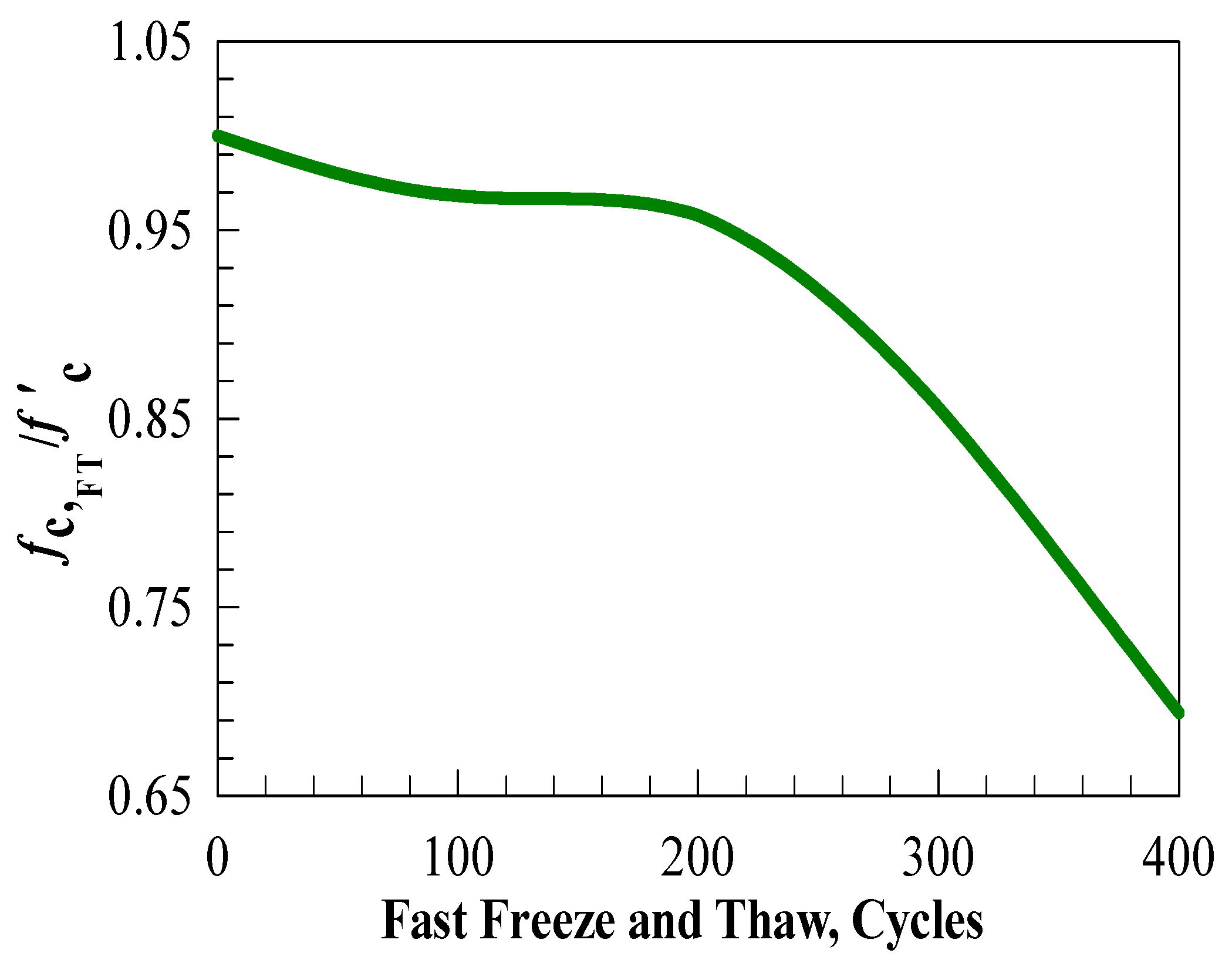
2.3.5. The Freezing-Thawing Effect

The effect of different numbers of freezing-thawing cycles was examined in this study, where the behavior of the NLFEA shear key joints was addressed. It is known that exposing the specimens to different numbers of freezing and thawing cycles reduces the concrete compressive strength with the values proposed by Huai-Shuai et al. [40], as illustrated in Figure 2. Consequently, the tensile strength and the elastic modulus of concrete exposed to a freezing-thawing action are also reduced. However, observing Figure 2 shows that exposing the concrete material to 100 freezing-thawing cycles reduces its compressive strength by 3.2% compared to 4.2% for 200 cycles, 14.4% for 300 cycles, and 30.6% for 400 freezing-thawing cycles.

2.3.6. The Investigated Parameters

After the validation stage was complete, a wide parametric study was carried out on the effect of lateral confinement pressure (1, 2, 3, 4, 5, and 6 MPa) and the effect of different numbers of freezing and thawing cycles (0, 100, 200, 300, and 400) using a ftotal o 30 NLFEA models. The results were reported in terms of their load-deflection behavior characteristics and cracking propagation. Specimens have an identical designation KJ-FT100-C1, where KJ is for keyed dry joint, FT100 is for exposure to 100 freeze and thaw cycles, and C is for a confinement level of 1 MPa, as seen in Table 1.

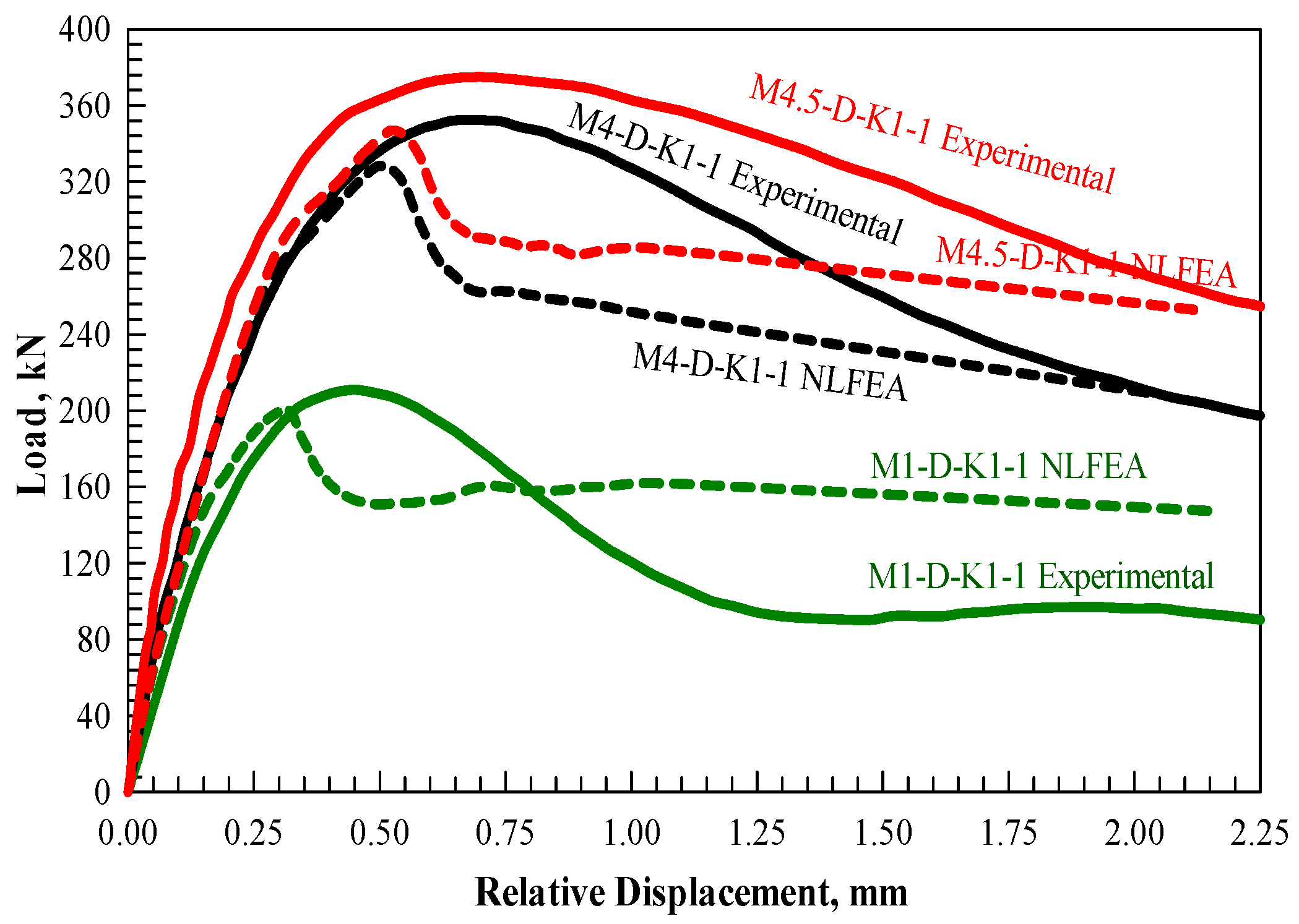
2.3.7. ABAQUS Model Validation

NLFEA validation was performed by comparing failure modes, cracking patterns, ultimate shear capacity, and associated deflection values, where values were compared between the NLFEA and experimental testing values, Figure 3 and Figure 4. Differences were minor, with values less than 5%, revealing a good ability for the simulated specimens to capture the real behavior of shear key joints. The cracking propagation and failure mode validation results are shown in Figure 3, where three cracking stages appear, as proposed by Kaneko et al. [41]. The three stages were the S-crack with curvilinear cracking propagation, followed by the cracks extending from the joint bottom and increasing into multiple ones, intensified at high concentration regions. Finally, there is propagation of multiple M-cracks, which are diagonal cracks, which ends with full concrete crushing, as reported by Jiang et al. [35].

3. New Theoretical Formula for Predicting Shear Key Joint Strength

The theoretical shear capacity formula introduced by Buyukozturk et al. [17] is presented in Equation (17) in terms of different variables: the prestressing stress ( σ n ) , the concrete compressive strength f c , and the joint interface area A f . The shear capacity formula by the AASHTO [15] proves to conservatively predict the shear strength of shear key specimens in terms of smooth key surface friction A s m and bearing area A k , as illustrated in Equation (18).
V u = A j ( 0.647 f c + 1.36 σ n )
V u = A k f c 0.205 σ n + 0.996 + 0.6 A s m σ n
ATEP, the Spanish design code [27], proposes the formula shown in Equation (19) for predicting the join’s shear capacity in terms of the joint area A j , the concrete compressive strength f c d , and the prestressing stress value σ n . Moreover, Rombach’s formula [24] considered the effect of the friction coefficient ( μ ) and presented a 0.2 safety factor ( γ F ), as per Equation (20). The AASHTO formula was reviewed and modified by Turmo et al. [20] using a wide experimental data set from the literature, ending up by modifying the concrete contribution f c m to the shear capacity, as shown in Equations (21) and (22).
V u = A j ( 0.564 f c + 1.41 σ n )
V u = ( μ σ n A j + 014 f c A k ) / γ F
V u = A k f c k 2 / 3 0.07 σ n + 0.33 + 0.6 σ n A s m     f c k 50   MPa
V u = A k   l n 1 + 0.1 f c m ( 0.49 σ n + 0.233 ) + 0.6 σ n A s m     f c k > 50   MPa
Alcalde et al. [26] proposed a formula for predicting the shear strength of shear key joints with confinement levels less than 3 MPa and concrete compressive strength that does not exceed 50 MPa, as shown in Equation (23), where N k is the number of shear keys.
V u = 7.118 A k 1 0.064 N k + 2.436 A s m σ n 1 + 0.127 N k  
The theoretical formulas mentioned concluded and listed the main contributing factors to the shear capacity of shear key joints, including concrete compressive strength, prestressing stress, friction coefficient, and lateral confinement level. However, the associated relationship and contribution percentages are not completely understood. The shear plane is the vertical projection of the contacted area of the key joints, as shown in Figure 1.
In this study, a new theoretical expression was introduced to predict the shear strength of key joints exposed to different numbers of freezing-thawing cycles and confinement levels, as shown in Figure 5. The average value of the normalized shear stress is addressed by dividing the maximum applied shear force shown in Figure 5 by the square root of the concrete strength multiplied by the shear plane area, and is plotted for each case of freezing and thawing cycle numbers. The results plotted in Figure 5 are a function of two major factors: the confinement level and the concrete compressive strength. Hou et al. [38] present the factors affecting the shear capacity of the shear key joints independent of the key shear area or geometry when the friction coefficient is higher than 0.35. In contrast, the confinement level and the concrete compressive strength contributions were obtained using the NLFEA results in this study using regression analysis, which appears in Figure 5 and is shown in Equation (24).
Figure 5. Theoretical model development.
Buildings 15 01892 g005
V u f c , F T A J = α β 0.00045 + 0.1575 σ n 0.9004  
σ n and A J are the lateral confinement pressure in MPa and the shear joint area in mm2, respectively. In addition, the α and β coefficients are regression factors obtained from the NLFEA results, reflecting the effect of freezing and thawing action on the shear capacity of the joint. The expression that appears in Equation (25) is a general formulation for determining the maximum longitudinal shear force, which may be obtained by substituting the values of these coefficients (Figure 5) into Equation (24):
V u = exp - 0.0007 cyles σ n 0.05 0.00045 + 0.1575 σ n 0.9004 f c , T A J  

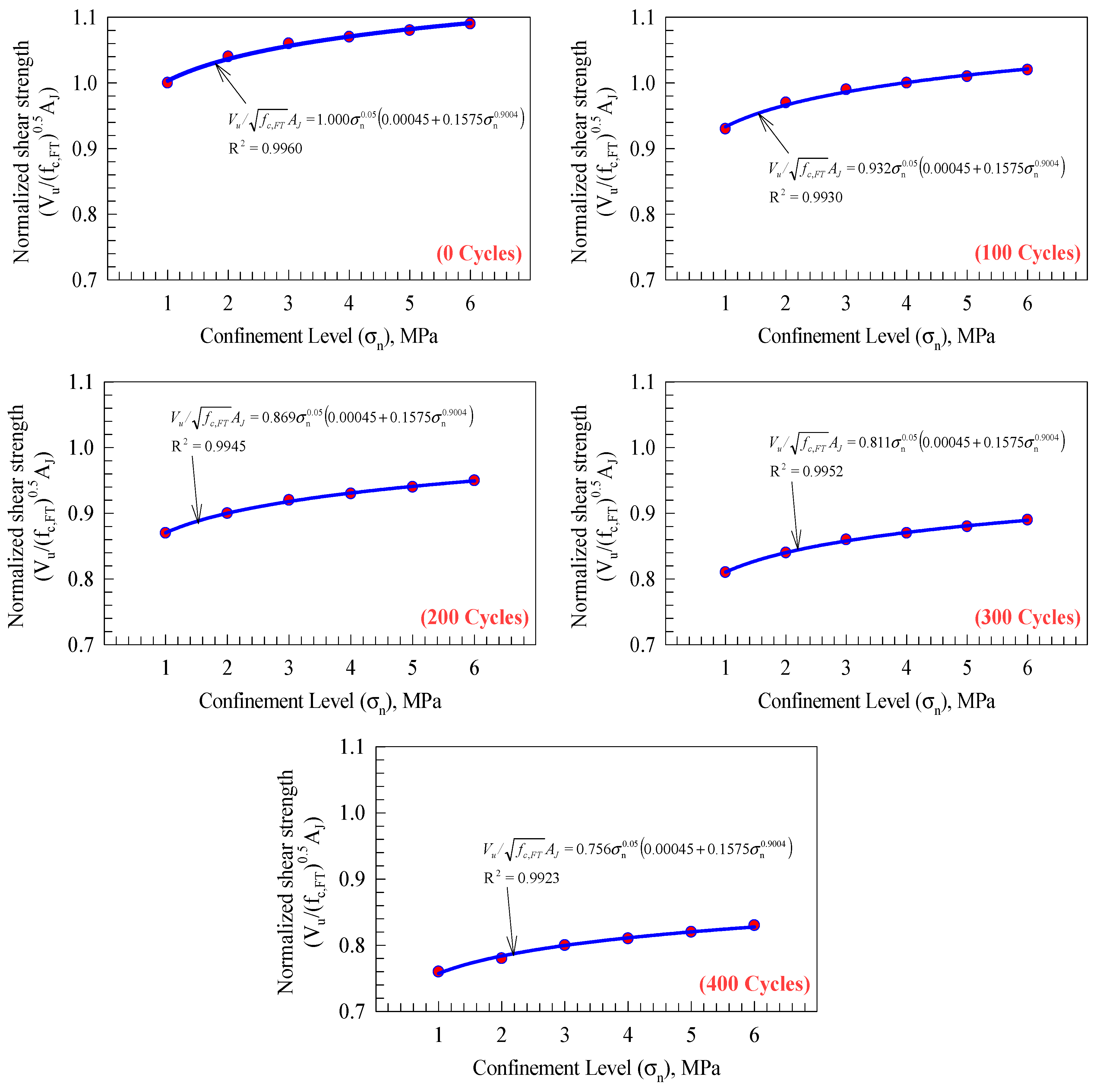
3.1. Results Comparison Against Numerical Data and Theoretical Formulas

During the validation stage, good agreement was found between the experimental and NLFEA results. Therefore, the shear strengths were also calculated using the new theoretical formula proposed in this study, where the effect of the different lateral confinement pressures and concrete compressive strength were addressed. The new model efficiently predicts the shear capacity, with differences ranging between 3.2% and 1.9%. The predicted values using the new model and the calculated ones using the different literature models were all plotted against the experimental values of the joints, as per Figure 6.
It was found that the new formula is effective in predicting the shear strength of the segmental bridge construction assembled using the post-tensioning technique. In addition, it was observed that the AASHTO [15] code prediction was the only one that had the closest predictions, compared to the large scattering and disturbance recorded for the other literature models. It was found that the ATEP code [35] provided the most accepted predictions under confinement pressure of less than 3 MPa and AASHTO code predictions [20]. The values predicted by the new theoretical expressions are very close to the experimentally obtained ones. In addition, the results reveal that increases in the lateral confinement pressure have a linearly increasing relationship with the predicted shear strengths. In addition, the statistical values (R2 and RMSE) for the results were also presented in Table 2, which confirms and demonstrates the accuracy of the new model and the AASHTO code in predicting the shear strength of the key joints.
Figure 6. Shear capacity prediction efficiency.
Buildings 15 01892 g006

3.2. Results Comparison Against Experimental Data

The predictability of the shear capacity formula presented in this research was examined in different numerical and experimental data from the literature, and the prediction was compared with AASHTO values, as per Table 3 [24,27,42,43]. However, different studies obtained good results with different lateral confinement pressure values and concrete compressive strength. The AASHTO results differed between 30% underestimation and 14% overestimation, compared to 30% underestimation and 25% overestimation for the new equation. However, the new model and the AASHTO code were chosen for comparison, since they give the closest predictions in the previous section. The statistical values (R2 and RMSE) of the results were also presented in Table 3, where the new model has a higher R2 value of 0.79 compared to only 0.46 for the AASHTO code, while the RMSE was lower by half, revealing the accuracy of the new expression.

4. NLFEA Results and Discussion

The validation stage revealed good agreement between the experimental and NLFEA results, revealing the availability to conduct the previously mentioned parametric study. The numerical results of the NLFEA models are presented in detail in Table 4, and the results are discussed and explained in the following sections.

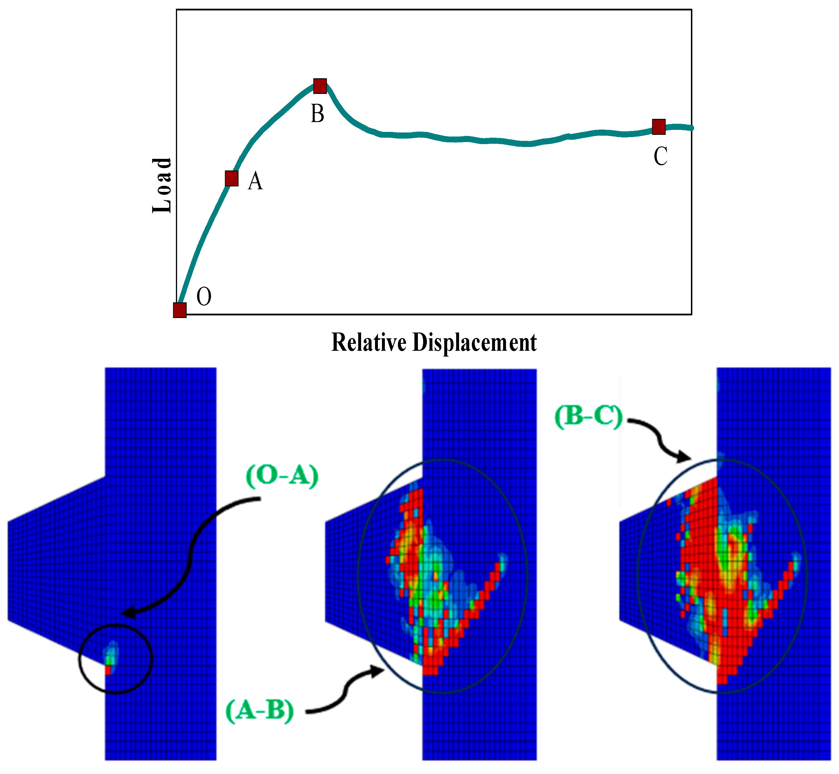
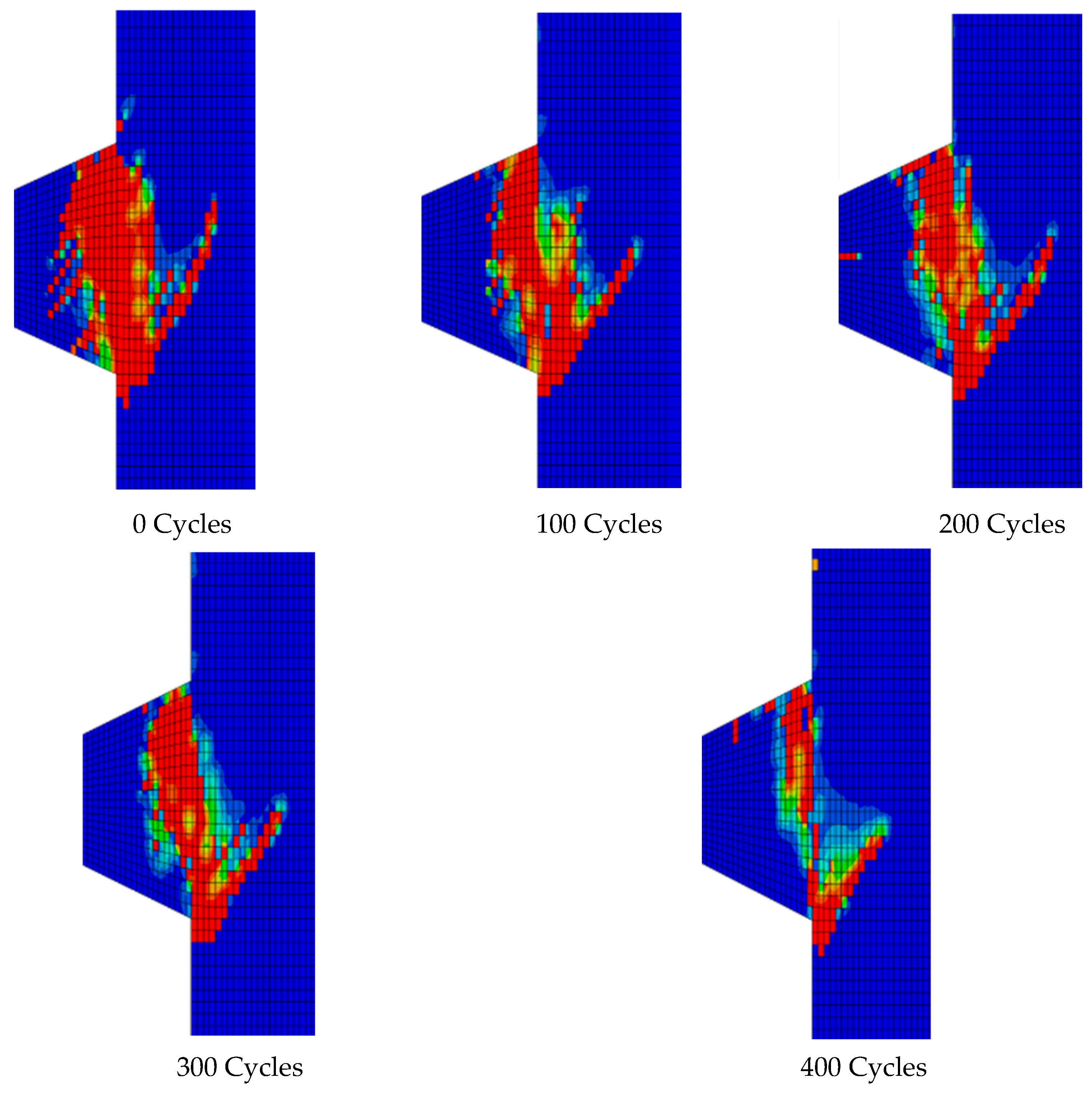
4.1. NLFEA Behavior and Concrete Damage

The load-deflection curves of the simulated specimens are plotted in Figure 7 and are mainly composed of three main stages. The first part extends between the O and A points, where it ends with increasing the applied tensile load to the concrete capacity in tension, where crack propagation takes place, as shown in Figure 7. The second stage extends between the A and B points, where nonlinear behavior exists with associated expansion and upward propagation of the tensile damage in the shear key. The final stage extends between B and C, where the load-deflection curve declines as failure occurs. The resulting crack appears diagonally at 45 degrees during the last stage of the loading history. Moreover, increasing the lateral confinement pressure decreases the resulting failure damage. The obtained NLFEA failure mode agrees with the experimentally obtained ones, with the tensile damage for specimens exposed to freezing and thawing cycles illustrated in Figure 8.

4.2. Crack Patterns

The detailed cracking propagation process is illustrated in Figure 9 using the induced strain criteria. However, the resulting concrete strain values exceed the ultimate cracking strain for concrete material, estimated as per the EC2 code as 0.0035, by ten times [25]. The simulated NLFEA specimens match the experimentally tested ones, especially in their failure modes and strain values. The cracking process starts at the lower bottom of the shear key and extends with 45 inclination degrees until the induced shear strength is about 60% to 80% from the specimen’s ultimate shear capacity, revealing initiation of the S-crack type. Once the ultimate shear strength is reached, the S-crack fully appears, followed by propagation of multiple cracks along the key length (M cracks). A large vertical crack appears where the multiple propagated ones are connected and open the shear key at their interface, where shearing-off behavior dominates the shear key behavior. A visible drop in the load-deflection curve appeared where the full concrete cracking and crushing occurred. It could be concluded that the cracking propagation obtained numerically by ABAQUS [31] is similar to the experimental one reported by Zhou et al. [23].

4.3. Cracking Propagation Process

The effect of lateral confinement pressure on cracking propagation is illustrated in Figure 10, where the shear key specimen’s behavior under different confinement levels is captured. The black areas appear and indicate cracking and associated separation of the connected regions where the compression strut is formed. Moreover, it is stated that increasing the lateral confinement pressure decreases the length of the propagated S-crack, revealing the role of the confinement level in stabilizing the crack propagation process where the shear key bearing carries the larger portion of the applied load.
Increasing the lateral confinement pressure to 6 MPa resulted in disappearance of the propagated crack, as per Figure 10. Propagation of the S-crack type could reflect its nature, as these cracks appear at the specimen’s sides at low-stress regions within the concrete material constituents and accordingly release energy [44]. Consequently, increasing the lateral confinement pressure increases the distribution of the compression stress concentration zones to include the entire shear key region, where the inclined crack disappears, and a new vertically propagated crack takes place, inducing a higher strain energy release rate.

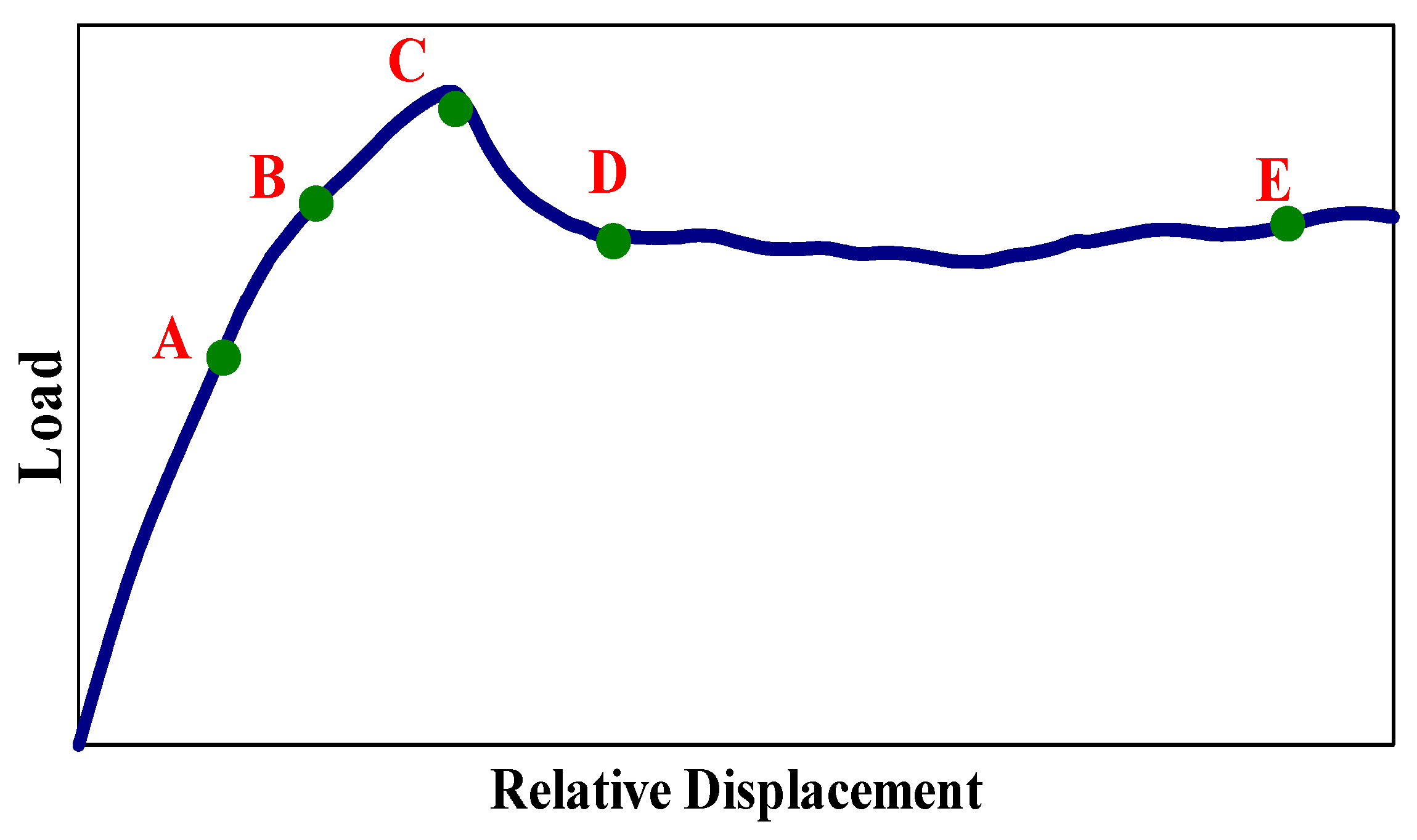
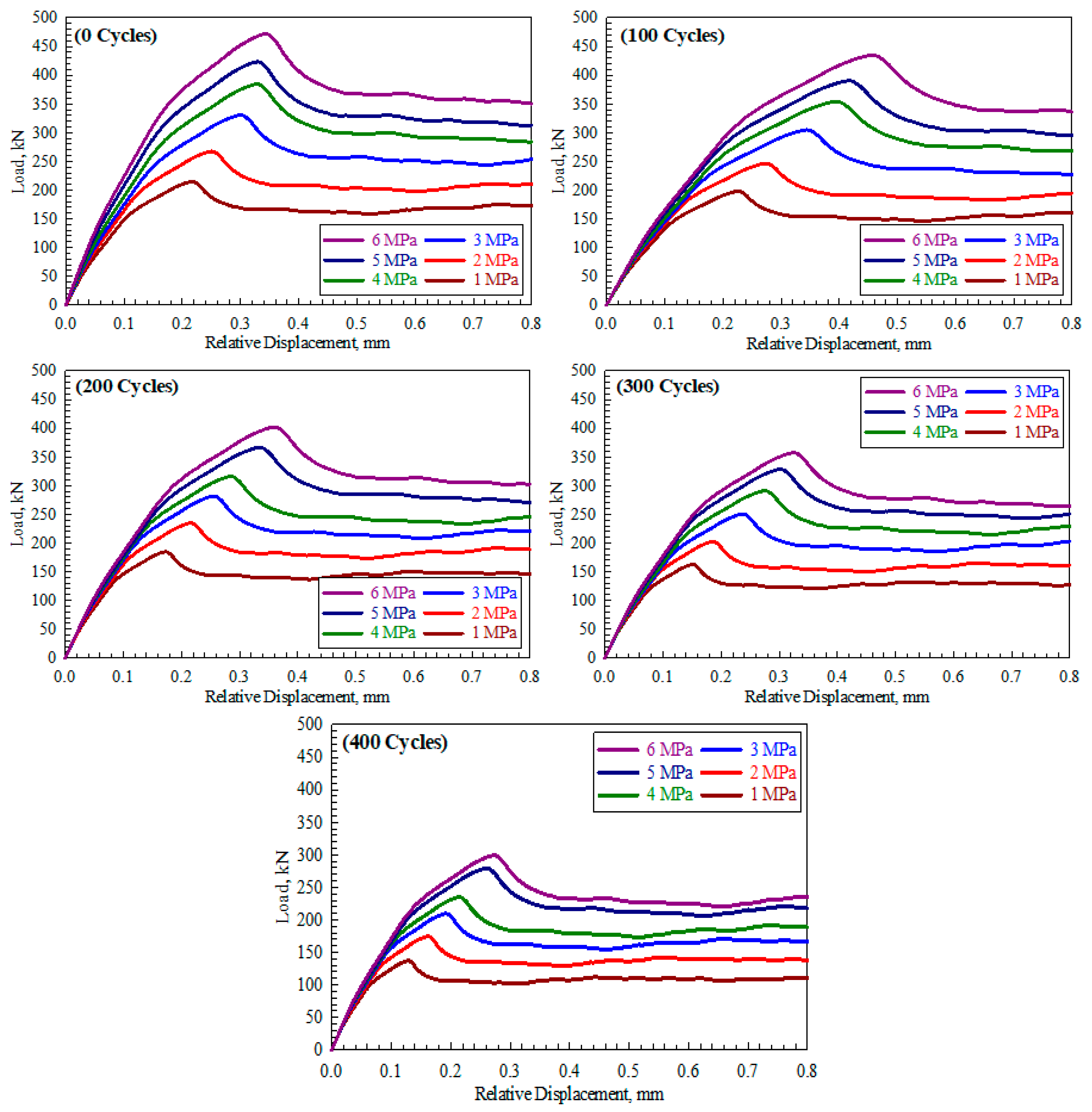
4.4. Load-Displacement Curves

The applied load versus the resulting deflection values are plotted in Figure 11 for all simulated specimens. Two main mechanisms resist vertically applied loading: the shear key bearing and the associated friction at the contracted areas. After failure occurrence, separation between the two connected parts occurs, starting from the bottom of the shear key and propagating to the upper part of the joint, forming the shearing-off phenomenon. The shear key loses its overall bearing capacity, resulting in a decline in load-deflection curve behavior. However, the load capacity experiences steady-state behavior after failure occurrence, forming residual shear strength capacity due to the friction forces surrounded by the lateral confinement pressure, as presented by Ahmed and Aziz [19].
A sudden drop in the load-deflection curves was observed, associated with the shearing-off phenomenon. Generally, increasing the confinement pressure applied to the joint increases its ultimate capacity. In contrast, increasing the number of freezing and thawing cycles reduces the ultimate shear capacity of the affected joint. The residual shear strength observed after the shearing-off phenomenon is due to friction forces between the cracked concrete parts under the effect of lateral confinement pressure. However, increasing the lateral confinement pressure value from 1 MPa to 6 MPa increases the resulting residual shear strength by a value depending on the concrete strength. Moreover, it has been observed that increasing the pressure increases the stiffness of the joints, along with the vertical deformation value, and this confirmed Buyukozturk et al.’s [17] conclusions. Finally, exposing the joints to freezing and thawing action reduces ultimate and residual strength.

4.5. Ultimate Shear Capacity and Corresponding Deflection Ratios

It has been stated previously that the shear key joint’s capacity is highly dependent on the level of confinement and the concrete compressive strength. The behavior of the load strength versus the number of freezing and thawing cycles is illustrated in Table 3 and Figure 12. Increasing the lateral confinement pressure for undamaged joint values to 2, 3, 4, 5, and 6 MPa increases the ultimate load-carrying capacity by 25, 54, 79, 97, and 120%, respectively, normalized with respect to an undamaged shear key joint (number of cycles = 0, with 1 MPa confinement level), as shown in Figure 12a. Moreover, exposing the shear key joint to 100 cycles of freezing and thawing reduces the ultimate capacity by 8% compared to an undamaged specimen at a 1 MPa confinement level, compared to increasing percentages of 15, 42, 65, 82, and 102% for lateral confinement values of 2, 3, 4, 5, and 6 MPa, respectively. In addition, increasing the number of freezing and thawing cycles to 200 increases the reduction percentage to 14% at 1 MPa pressure, compared to enhancement percentages of 9, 31, 47, 71, and 87% for confinement pressure values of 2, 3, 4, 5, and 6 MPa, respectively, as per Figure 12a.
The ultimate capacity of shear key joints with 300 freezing and thawing cycles is reduced by 24% and 6% for joints with confinement pressure values of 1 MPa and 2 MPa, respectively, normalized with respect to an undamaged joint, compared to enhancement percentages of 17, 35, 53, and 66% for increasing the confinement values to 3, 4, 5, and 6 MPa, respectively. In addition, the ultimate capacity is reduced by 36, 16, and 2% for confinement pressure values of 1, 2, and 3 MPa, respectively, for specimens exposed to 400 cycles of freezing and thawing, compared to increasing percentages of 9, 30, and 39%, for lateral confinement pressure values of 4, 5, and 6 MPa. At the same time, the corresponding deflection percentages equal almost half of the ultimate load percentages (Figure 12b). Therefore, confinement pressure values of 2, 2, 3, and 4 MPa are classified as the minimum required confinement values for specimens exposed to freezing and thawing cycles of 100, 200, 300, and 400, respectively, to maintain their structural performance without any degradation.
The resulting enhancement percentages observed in the shear key joint’s structural behavior at the ultimate stage upon increasing the lateral confinement pressure decreases as the number of freezing and thawing cycles increases. However, this could be related to the induced large stress values exceeding the concrete strength capacity, limiting the confinement effect on the ultimate load-carrying capacity. The normalization method of average shear stress values is compatible with the shear design steps provided by AASHTO, where the effect of the different strength grades is omitted.

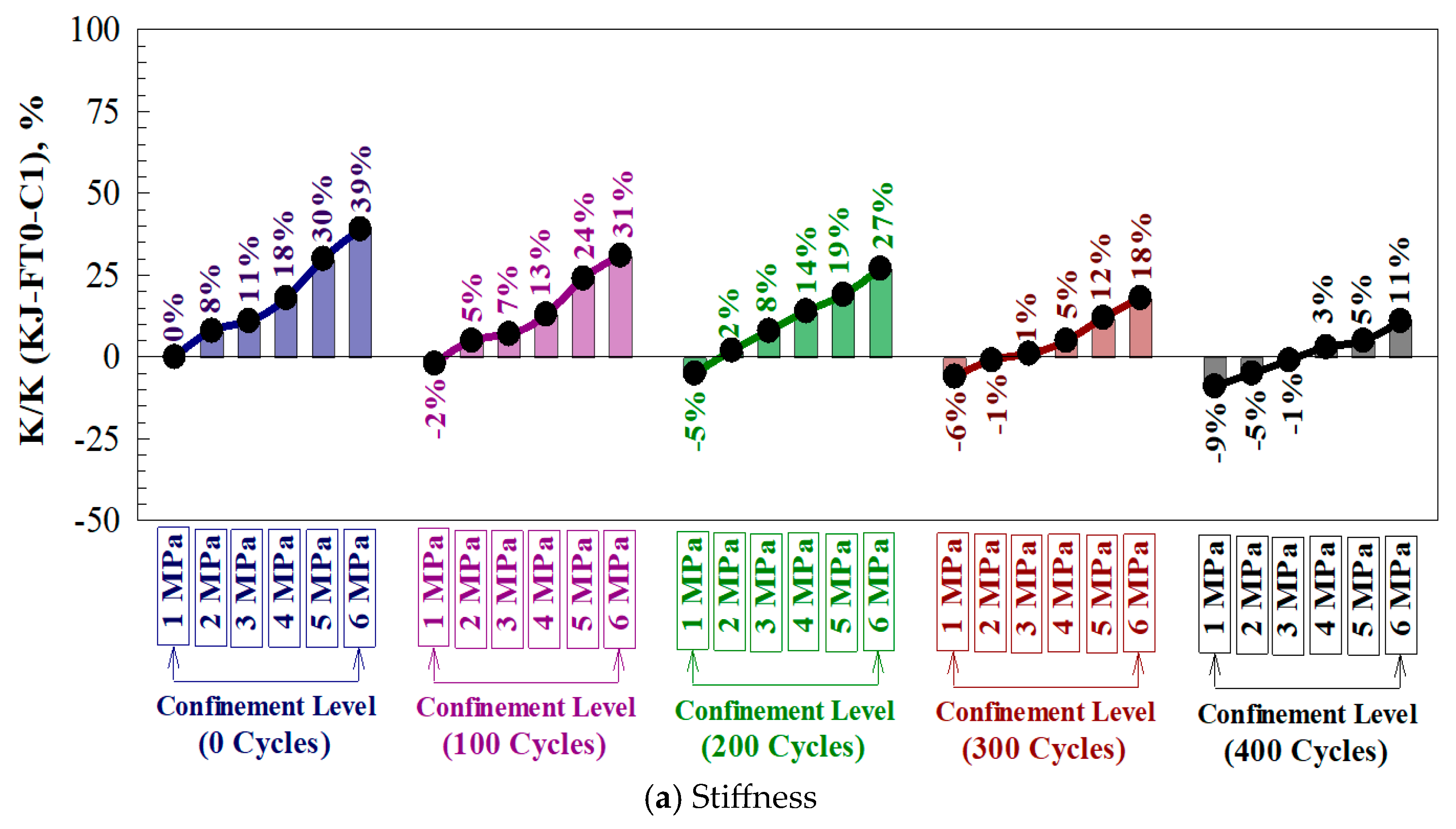
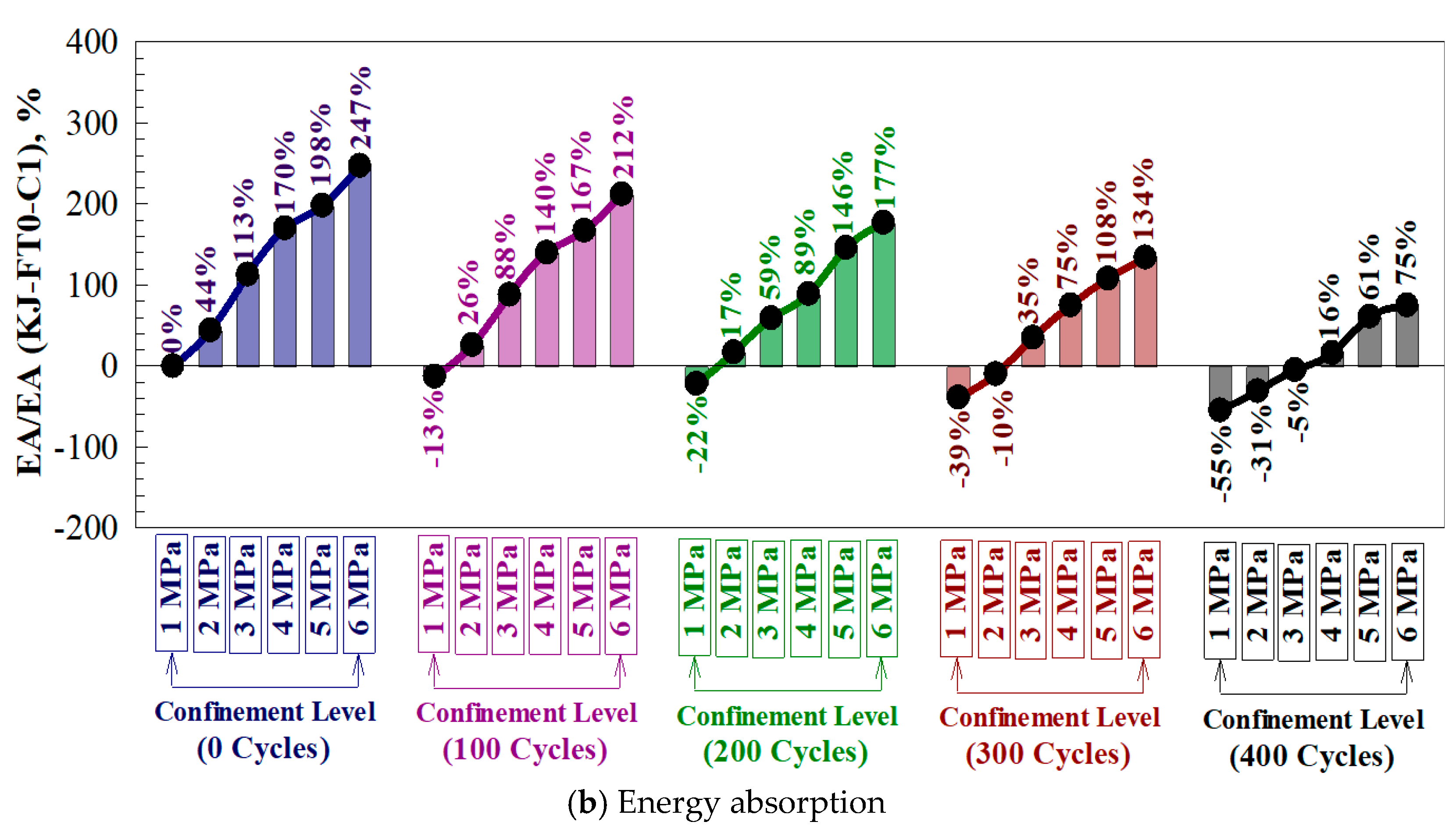
4.6. Stiffness and Energy Absorption Ratios

The ability of a material to maintain its structural behavior under loading increment is known as stiffness and is calculated as the ratio between the cracking load and the cracking deflection values. The overall area under the load-deformation curve is the energy absorption capacity. Exposing the shear key joints to 100, 200, 300, and 400 freezing and thawing cycles reduces the stiffness capacities by 4, 6, 11, and 14%, normalized with respect to the undamaged specimen, as per Figure 13a. In addition, the energy absorption is reduced by 11, 22, 34, and 52%, as shown in Figure 13b for 100, 200, 300, and 400 freezing and thawing cycles, respectively. In contrast, increasing the lateral confinement to 2, 3, 4, 5, and 6 MPa increases the join’s stiffness by 6, 10, 16, 23, and 31%, respectively, normalized with respect to a specimen with a 1 MPa confinement pressure value, compared to increasing percentages of 47, 113, 167, 219, and 263% for the energy absorption capacity.

5. Conclusions

The NLFEA method was used to investigate the behavior of single-shear-key joints under the effect of different confinement levels and freezing-thawing cycles. Based on the results obtained, the following could be concluded:
  • Two main shear transfer mechanisms contribute to the shear capacity of a single dried key joint: key bearing and friction. The observed failure is associated with a 45-degree inclination crack, shearing-off, concrete crushing, and joint slippage.
  • The propagated cracks are significantly affected by the amount of lateral confinement provided, where cracks are shortened and narrowed at high confinement levels until they become invisibly propagated.
  • Exposing the shear keys to 100, 200, 300, and 400 freeze and thaw cycles reduces the ultimate shear capacity by 8, 15, 24, and 36%, respectively, compared to 4, 9, 14, and 25% for the ultimate deflection, 6, 11, and 14% for the stiffness, and 11, 22, 34, and 42% for the energy absorption.
  • Providing a confinement level of 2, 3, 4, 5, and 6 MPa improves the overall behavior, where increasing percentages of 25, 53, 76, 99, and 119% and 18, 39, 52, 61, and 67% were recorded for the ultimate load and ultimate deflection, compared to 6, 10, 16, 23, and 31% and 47, 113, 167, 219, and 263% for the stiffness and energy absorption.
  • A new expression was proposed for predicting single-shear key capacity, where good predictions were recorded with an average standard deviation value of less than 4% in the conservative direction.
  • The results of this study are subject to some limitations regarding the concrete material grade, where it applies to normal concrete strength only and it is not valid for high and ultra-high grades due to their different behavior.

Author Contributions

Conceptualization, B.R.A. and R.A.-R.; methodology, B.R.A. and R.A.-R.; formal analysis, B.R.A. and R.A.-R.; investigation, B.R.A. and R.A.-R.; resources, B.R.A. and R.A.-R.; data curation, B.R.A. and R.A.-R.; writing—original draft preparation, B.R.A. and R.A.-R.; writing—review and editing, B.R.A.; visualization, B.R.A. and R.A.-R.; supervision, B.R.A. and R.A.-R.; project administration, B.R.A. and R.A.-R. All authors have read and agreed to the published version of the manuscript.

Funding

This research received no external funding.

Data Availability Statement

Data are contained within the article.

Acknowledgments

This work was fully supported by Jordan University of Science, and this support is gratefully acknowledged.

Conflicts of Interest

The authors declare no conflicts of interest.

References

  1. Pan, R.; Yang, P.; Shi, X.; Zhang, T. Effects of freeze–thaw cycles on the shear stress induced on the cemented sand–structure interface. Constr. Build. Mater. 2023, 371, 130671. [Google Scholar] [CrossRef]
  2. Wang, W.; Li, J.; Chen, P.; Zhou, C.; Wang, Z. Effects of Freeze-Thaw Cycles on Interfacial Shear Transfer Characteristics in Section Steel Reinforced Concrete Composite Structures with Stud Connectors. Eng. Struct. 2024, 307, 117948. [Google Scholar] [CrossRef]
  3. Al-Rousan, R.Z.; Alnemrawi, B.a.R. Impact of column axial load level of the seismic behavior of concrete-filled UHPC tubular column-to-footing connections reinforced with different spiral stirrup spacing. Results Eng. 2025, 26, 104952. [Google Scholar] [CrossRef]
  4. Yun, Y.; Wu, Y.-F. Durability of CFRP–concrete joints under freeze–thaw cycling. Cold Reg. Sci. Technol. 2011, 65, 401–412. [Google Scholar] [CrossRef]
  5. Özgan, E.; Serin, S. Investigation of certain engineering characteristics of asphalt concrete exposed to freeze–thaw cycles. Cold Reg. Sci. Technol. 2013, 85, 131–136. [Google Scholar] [CrossRef]
  6. Wang, W.; Zhang, X.; Yu, S.; Guan, J. Effect of Cyclic Soil Freezing and Thawing on the Lateral Load Response of Bridge Pile Foundations. Buildings 2024, 14, 2540. [Google Scholar] [CrossRef]
  7. Dong, L.; Liu, J.; Wang, K.; Tian, S.; Su, Y. The Longitudinal Push-Out Effect and Differential Settlement Control Measures of the Transition Section of Road and Bridge Induced by Freeze–Thaw Inducing. Sustainability 2024, 16, 9972. [Google Scholar] [CrossRef]
  8. Zou, Y.; Xu, D. Mechanical Characteristics of Steel Shear Keyed Joints in the Construction and Finished States. Adv. Civ. Eng. 2021, 2021, 7252122. [Google Scholar] [CrossRef]
  9. Wang, X.; Li, L.; Mu, W.; Yang, T.; Du, Y.; Lu, J. Damage characteristics and mechanisms of shear strength at the interface between fiber-reinforced concrete and rock under freeze-thaw cycles. J. Build. Eng. 2024, 98, 111191. [Google Scholar] [CrossRef]
  10. Xiao, L.; Wei, X.; Kang, Z.; Zhang, J.; Zhan, G. Numerical Studies on the Performance Degradation of Headed Stud Shear Connectors in Composite Structures Under Freeze–Thaw Cycles. Int. J. Civ. Eng. 2024, 22, 639–653. [Google Scholar] [CrossRef]
  11. Al-Rousan, R.Z.; Alnemrawi, B.a.R. The extent of high-temperatures on the interfacial shear strength of CFRP-strengthened shear keys: NLFEA and theoretical calculation. Comput. Concr. 2025, 35, 441. [Google Scholar] [CrossRef]
  12. Gerges, N.N.; Issa, C.A.; Fawaz, S. The effect of construction joints on the flexural bending capacity of singly reinforced beams. Case Stud. Constr. Mater. 2016, 5, 112–123. [Google Scholar] [CrossRef]
  13. Zou, Y.; Xu, D. Experimental study on shear behavior of joints in precast concrete segmental bridges. Structures 2022, 39, 323–336. [Google Scholar] [CrossRef]
  14. Ahmed, G.H.; Aziz, O.Q. Shear behavior of dry and epoxied joints in precast concrete segmental box girder bridges under direct shear loading. Eng. Struct. 2019, 182, 89–100. [Google Scholar] [CrossRef]
  15. AASHTO. Guide Specifications for Design and Construction of Segmental Concrete Bridges 2024; American Association of State Highway and Transportation Officials: Washington, DC, USA, 2024. [Google Scholar]
  16. Mohamad, M.E.; Ibrahim, I.S.; Abdullah, R.; Abd Rahman, A.B.; Kueh, A.B.H.; Usman, J. Friction and cohesion coefficients of composite concrete-to-concrete bond. Cem. Concr. Compos. 2015, 56, 1–14. [Google Scholar] [CrossRef]
  17. Buyukozturk, O.; Bakhoum, M.M.; Beattie, S.M. Shear Behavior of Joints in Precast Concrete Segmental Bridges. J. Struct. Eng. 1990, 116, 3380–3401. [Google Scholar] [CrossRef]
  18. Ahmed, G.H.; Aziz, O.Q. Shear strength of joints in precast posttensioned segmental bridges during 1959–2019, review and analysis. Structures 2019, 20, 527–542. [Google Scholar] [CrossRef]
  19. Ahmed, G.H.; Aziz, O.Q. Stresses, deformations and damages of various joints in precast concrete segmental box girder bridges subjected to direct shear loading. Eng. Struct. 2020, 206, 110151. [Google Scholar] [CrossRef]
  20. Turmo, J.; Ramos, G.; Aparicio, A. Towards a model of dry shear keyed joints: Modelling of panel tests. Comput. Concr. 2012, 10, 469–487. [Google Scholar] [CrossRef]
  21. Li, G.; Yang, D.; Lei, Y. Combined Shear and Bending Behavior of Joints in Precast Concrete Segmental Beams with External Tendons. J. Bridge Eng. 2013, 18, 1042–1052. [Google Scholar] [CrossRef]
  22. Algorafi, M.A.; Ali, A.A.A.; Othman, I.; Jaafar, M.S.; Anwar, M.P. Experimental study of externally prestressed segmental beam under torsion. Eng. Struct. 2010, 32, 3528–3538. [Google Scholar] [CrossRef]
  23. Zhou, X.; Mickleborough, N.; Li, Z. Shear Strength of Joints in Precast Concrete Segmental Bridges. ACI Struct. J. 2005, 102, 3–11. [Google Scholar] [CrossRef]
  24. Rombach, G. Precast segmental box girder bridges with external prestressing-design and construction. Segmental Bridges INSA Rennes 2002, 19, 1–15. [Google Scholar]
  25. EC2. Eurocode 2: Design of Concrete Structures—Part 1-1: General Rules and Rules for Buildings; British Standard Institution: London, UK, 2004. [Google Scholar]
  26. Alcalde, M.; Cifuentes, H.; Medina, F. Influence of the number of keys on the shear strength of post-tensioned dry joints. Mater. Construcción 2013, 63, 297–307. [Google Scholar] [CrossRef]
  27. del Pozo Vindel, F.J. Información sobre ATEP (Asociación Técnica Española del Pretensado), GEHO (Grupo Español del Hormigón), FIP (Federación Internacional del Pretensado) y CEB (Comité Eurointernacional del Hormigón). Hormigón Y Acero 1996, 202, 9–12. [Google Scholar]
  28. Kim, T.-H.; Kim, Y.-J.; Jin, B.-M.; Shin, H.-M. Numerical study on the joints between precast post-tensioned segments. Int. J. Concr. Struct. Mater. 2007, 19, 3–9. [Google Scholar] [CrossRef]
  29. Liu, T.; Wang, Z.; Guo, J.; Wang, J. Shear Strength of Dry Joints in Precast UHPC Segmental Bridges: Experimental and Theoretical Research. J. Bridge Eng. 2019, 24, 04018100. [Google Scholar] [CrossRef]
  30. Turmo, J.; Ramos, G.; Aparicio, A.C. Shear strength of dry joints of concrete panels with and without steel fibres: Application to precast segmental bridges. Eng. Struct. 2006, 28, 23–33. [Google Scholar] [CrossRef]
  31. ABAQUS Dassault Systemes Simulia Corp. P (2024) ABAQUS Analysis User’s Guide (6.24), 14th ed.; ABAQUS Dassault Systemes Simulia Corp.: Providence, RI, USA, 2024. [Google Scholar]
  32. Al-Rousan, R.Z.; Alnemrawi, B.a.R. Interaction diagram of rectangular RC columns confined with CFRP composite under biaxial bending. Structures 2025, 75, 108833. [Google Scholar] [CrossRef]
  33. Al-Rousan, R.Z.; Alnemrawi, B.a.R. Empirical and precise finite element modelling of bond-slip contact behavior between heat-damaged concrete and anchored CFRP composites with groove. Eng. Struct. 2025, 332, 120042. [Google Scholar] [CrossRef]
  34. Kmiecik, P.; KamiŃSki, M. Modelling of reinforced concrete structures and composite structures with concrete strength degradation taken into consideration. Arch. Civ. Mech. Eng. 2011, 11, 623–636. [Google Scholar] [CrossRef]
  35. Jiang, H.; Chen, L.; Ma, Z.J.; Feng, W. Shear Behavior of Dry Joints with Castellated Keys in Precast Concrete Segmental Bridges. J. Bridge Eng. 2015, 20, 04014062. [Google Scholar] [CrossRef]
  36. Shamass, R.; Zhou, X.; Alfano, G. Finite-Element Analysis of Shear-Off Failure of Keyed Dry Joints in Precast Concrete Segmental Bridges. J. Bridge Eng. 2015, 20, 04014084. [Google Scholar] [CrossRef]
  37. Wai, C.; Rivai, A.; Bapokutty, O. Modelling Optimization Involving Different Types of Elements in Finite Element Analysis. In IOP Conference Series: Materials Science and Engineering; IOP Publishing: Bristol, UK, 2013; Volume 1, p. 012036. [Google Scholar] [CrossRef]
  38. Hou, W.; Peng, M.; Jin, B.; Tao, Y.; Guo, W.; Zhou, L. Influencing Factors and Shear Capacity Formula of Single-Keyed Dry Joints in Segmental Precast Bridges under Direct Shear Loading. Appl. Sci. 2020, 10, 6304. [Google Scholar] [CrossRef]
  39. Garg, A.K.; Abolmaali, A. Finite-Element Modeling and Analysis of Reinforced Concrete Box Culverts. J. Transp. Eng. 2009, 135, 121–128. [Google Scholar] [CrossRef]
  40. Shang, H.-s.; Cao, W.-q.; Wang, B. Effect of Fast Freeze-Thaw Cycles on Mechanical Properties of Ordinary-Air-Entrained Concrete. Sci. World J. 2014, 2014, 923032. [Google Scholar] [CrossRef] [PubMed]
  41. Kaneko, Y.; Connor, J.J.; Triantafillou, T.C.; Leung, C.K. Fracture Mechanics Approach for Failure of Concrete Shear Key. I: Theory. J. Eng. Mech. 1993, 119, 681–700. [Google Scholar] [CrossRef]
  42. Jiang, H.; Li, Y.; Liu, A.; Ma, Z.J.; Chen, L.; Chen, Y. Shear Behavior of Precast Concrete Segmental Beams with External Tendons. J. Bridge Eng. 2018, 23, 04018049. [Google Scholar] [CrossRef]
  43. Yang, I.-H.; Kim, K.-C.; Kim, Y.-J. Shear Strength of Dry Joints in Precast Concrete Modules. In Proceedings of the Thirteenth East Asia-Pacific Conference on Structural Engineering and Construction (EASEC-13), Sapporo, Japan, 11–13 September 2013; pp. 1–5. [Google Scholar]
  44. Bažant, Z.P.; Pfeiffer, P.A. Shear fracture tests of concrete. Mater. Struct. 1986, 19, 111–121. [Google Scholar] [CrossRef]
Figure 1. Shear key joint geometry, reinforcement, loading, and supporting boundary condition details.
Buildings 15 01892 g001
Figure 2. The effect of fast freezing-thawing cycles on concrete compressive strength.
Buildings 15 01892 g002
Figure 3. Crack formulation sequence and final failure mode.
Buildings 15 01892 g003
Figure 4. Shear key joint validation.
Buildings 15 01892 g004
Figure 7. Typical tensile damage and crack propagation sequence.
Buildings 15 01892 g007
Figure 8. Final tensile damage of a specimen under various numbers of freeze and thaw cycles.
Buildings 15 01892 g008
Figure 9. The tensile strain propagation process in concrete material.
Buildings 15 01892 g009
Figure 10. The effect of different confinement levels on key joint cracking behavior.
Buildings 15 01892 g010
Figure 11. Load vs. displacement curves.
Buildings 15 01892 g011
Figure 12. Normalized (a) ultimate load and (b) corresponding deflection with respect to KJ-FT0-C1.
Buildings 15 01892 g012
Figure 13. Normalized (a) stiffness and (b) energy absorption with respect to KJ-FT0-C1.
Buildings 15 01892 g013aBuildings 15 01892 g013b
Table 1. Keyed joint designation.
Keyed Joint DesignationFast Freeze-Thaw Cycles [40]Level of Confinement, MPa f c , MPa [40]
KJ-FT0-C10150.0
KJ-FT0-C2250.0
KJ-FT0-C3350.0
KJ-FT0-C4450.0
KJ-FT0-C5550.0
KJ-FT0-C6650.0
KJ-FT100-C1100148.4
KJ-FT100-C2248.4
KJ-FT100-C3348.4
KJ-FT100-C4448.4
KJ-FT100-C5548.4
KJ-FT100-C6648.4
KJ-FT200-C1200147.9
KJ-FT200-C2247.9
KJ-FT200-C3347.9
KJ-FT200-C4447.9
KJ-FT200-C5547.9
KJ-FT200-C6647.9
KJ-FT300-C1300142.8
KJ-FT300-C2242.8
KJ-FT300-C3342.8
KJ-FT300-C4442.8
KJ-FT300-C5542.8
KJ-FT300-C6642.8
KJ-FT400-C1400134.7
KJ-FT400-C2234.7
KJ-FT400-C3334.7
KJ-FT400-C4434.7
KJ-FT400-C5534.7
KJ-FT400-C6634.7
Table 2. Theoretical prediction statistical properties (Figure 6 results).
CriteriaNew ModelBuyukozturkAASHTORombachTurmoATEP
R20.9640.9450.9550.8940.9520.946
RMSE34.85094.84430.75786.900118.37025.265
Table 3. Experimental shear capacity predictions.
Ref.Specimen Designation f c , (MPa) ξ , (MPa)(AJ) (mm2)ExperimentalNew ModelAASHTO
V u E x p
(kN)
V u E q n (kN) E r r o r % V u A A S H T O (kN) E r r o r %
[31]S60-H10-P1641.017,000768714717
S60-H10-P2642.017,00010510618816
S60-H10-P3643.017,000131125510520
S70-H10-P1641.017,000868717117
S70-H10-P2642.017,00010810628819
S70-H10-P3643.017,000135125710522
S70-H20-P1641.017,000878707118
S70-H20-P3643.017,000112125121056
[43]K1-01421.020,00090838978
K1-02422.020,0001141011112611
K1-03411.020,000918210892
K1-04411.020,00095821410814
R 2 0.790.46
RMSE8.716.3
Table 4. Keyed joint NLFEA results.
Model Designation u , mm P u , kN k , kN/mm A ( P D ) , kN.mm σ u , MPa τ u f c V u , kN V u V u , NLFEA
KJ-FT0-C10.2175214.818801104.300.61214.81.000
KJ-FT0-C20.2511267.520281595.350.76272.41.018
KJ-FT0-C30.3006330.620942356.610.94326.40.987
KJ-FT0-C40.3286384.322262987.691.09378.60.985
KJ-FT0-C50.3294423.224463298.461.20429.71.015
KJ-FT0-C60.3436471.726143839.431.33479.91.017
KJ-FT100-C10.2052198.11837963.960.56197.10.995
KJ-FT100-C20.2386246.619681394.930.70249.91.013
KJ-FT100-C30.2876304.820182076.100.86299.40.982
KJ-FT100-C40.3164354.321322657.091.00347.30.980
KJ-FT100-C50.3192390.223272947.801.10394.21.010
KJ-FT100-C60.3350435.024723448.701.23440.31.012
KJ-FT200-C10.1963184.81792863.700.52182.80.989
KJ-FT200-C20.2335234.819141294.700.66231.80.987
KJ-FT200-C30.2632281.720381755.630.80277.70.986
KJ-FT200-C40.2797316.021512096.320.89322.11.019
KJ-FT200-C50.3133366.722282717.331.04365.60.997
KJ-FT200-C60.3216402.223813058.041.14408.31.015
KJ-FT300-C10.1753162.71767673.250.46161.10.990
KJ-FT300-C20.2067202.61866994.050.57204.31.008
KJ-FT300-C30.2526250.418881495.010.71244.80.977
KJ-FT300-C40.2815291.119681935.820.82283.90.975
KJ-FT300-C50.2963328.521112306.570.93322.20.981
KJ-FT300-C60.3058357.322242587.151.01359.91.007
KJ-FT400-C10.1529137.41711502.750.39135.30.984
KJ-FT400-C20.1853174.61794763.490.49171.50.982
KJ-FT400-C30.2127209.518761054.190.59205.50.981
KJ-FT400-C40.2300235.019451284.700.66238.41.014
KJ-FT400-C50.2699279.519721785.590.79270.50.968
KJ-FT400-C60.2735299.120821935.980.85302.21.010
Note: u is the ultimate deflection, P u is the ultimate load, k is the stiffness, A ( P D ) is the toughness, σ u is the ultimate stress, τ u is the shear stress, f c is the concrete compressive strength, and V u is the ultimate shear force.
Disclaimer/Publisher’s Note: The statements, opinions and data contained in all publications are solely those of the individual author(s) and contributor(s) and not of MDPI and/or the editor(s). MDPI and/or the editor(s) disclaim responsibility for any injury to people or property resulting from any ideas, methods, instructions or products referred to in the content.

