1. Introduction
Reinforced concrete (RC) is one of the most used composite materials in large-scale civil engineering structures. However, its durability has long been a critical issue affecting service life, with reinforcement corrosion being one of the primary causes of premature failure. Worldwide, several methods have been employed to protect reinforced concrete from corrosion. These include modifying the chemical composition of the reinforcing steel, repairing corrosion-damaged concrete covers, applying anti-corrosion coatings to the reinforcement, incorporating corrosion inhibitors into the concrete mix, using waterproof coatings on concrete surfaces, and implementing electrochemical protection measures. Among these techniques, impressed current cathodic protection (ICCP) has been extensively researched and applied globally due to its technical advantage in directly inhibiting the electrochemical corrosion of reinforcement, particularly for structures exposed to Cl
− contamination [
1,
2,
3,
4,
5,
6].
In the Fe-H
2O system, the Pourbaix diagram can be roughly divided into three regions: the corrosion region (where the reinforcement corrodes rapidly), the passivation region (where the corrosion rate is very low), and the immunity region (the stable zone where the reinforcement is essentially uncorroded) [
7]. When a conductive anode material is applied to the exterior of the concrete and connected to the reinforcement, and an external power supply polarizes both the anode and the reinforcement (cathode), a protection circuit is formed. Under the influence of the power supply, the reinforcement is cathodically polarized to a relatively negative potential (generally less than −900 mV vs. a saturated calomel electrode (SCE)) [
8], placing it in the immunity region and inhibiting the anodic dissolution reaction, thereby preventing the thermodynamically driven corrosion of the reinforcement [
7]. In addition to reducing the corrosion rate by polarizing the reinforcement, ICCP can also inhibit reinforcement corrosion by increasing the pH at the reinforcement/concrete interface and reducing Cl
− concentration, thereby shifting the pitting potential positively, and also by enhancing the stability of the passive film on the reinforcement surface and maintaining a high-alkaline interface that effectively protects the reinforced concrete from corrosive damage [
9]. Therefore, provided that sufficient protection current is applied, ICCP can offer long-term corrosion protection for RC structures.
Under the impressed current of ICCP, the external anode mortar—especially in regions directly contacting the anode metal—undergoes the following anodic reactions [
10]:
Under alkaline conditions, reaction (1) predominates; when the alkalinity decreases to a certain level, reaction (2) occurs. Additionally, in Cl
−-containing pore solutions, the following anodic reactions take place simultaneously:
These reactions continuously consume OH
− and generate H
+ in the pore solution in the external anode region, thereby lowering the local pH and causing acidification. This, in turn, promotes the dissolution of Ca(OH)
2:
When the pH of the pore solution near the metal anode falls below that of a saturated Ca(OH)
2 solution, Ca(OH)
2 gradually dissolves, increasing the porosity of the anode mortar and leading to localized cracking and debonding of the primary anode [
11]. The overall electrical resistivity thus increases, resulting in higher concrete permeability and uneven distribution of the protection current, which severely affects the efficiency of the ICCP system. Furthermore, once the Ca(OH)
2 near the anode metal is exhausted due to anodic reactions, the concrete’s high resistivity and the low current required for protection cause a reduced ion migration rate. Consequently, when distant OH
− cannot replenish the deficit in time, the primary anodic reaction shifts from (1) to (2), causing a sharp decline in the mortar’s alkalinity and adversely affecting the durability of the entire anode system. Additionally, the acidification and erosion processes alter the composition, morphology, and microstructure of the mortar’s mineral components, further affecting its electrical uniformity and the overall stability of the ICCP system [
12]. In practical applications, this necessitates frequent removal and replacement of the anode materials, significantly reducing the system’s efficiency.
Research on acidification and erosion effects under a direct current (DC) field has primarily focused on high current densities (2 A/m
2)—specifically, on the impact and mechanisms of acidification induced by electrochemical chloride extraction (ECE) technology. It has been observed that ECE increases the concrete’s porosity and pore size. Orellan et al. [
13] found that the acidification effect of the applied current influences the composition and structure of hydration products in the mortar, thereby compromising the bond at the anode interface. Carmona [
14] reported that after ECE, the pH of the electrolyte near the anode dropped from 7 to approximately 5, possibly due to the combined effects of OH
− oxidation, water decomposition, and carbonation. Jansson et al. developed carbon-based conductive coatings for the utilization as an anode material in an ICCP system to replace the titanium mesh generally used to improve the anode long-term performance [
15]; however, the cost will be increased.
In contrast, there is relatively little research on the acidification and erosion effects produced by low current densities in ICCP. Peelen et al. [
16] established the co-equilibrium relationship among Ca
2+, OH
−, and Ca(OH)
2 under ICCP based on the Nernst–Planck equation, simulating the range of the acidification effect. Bertolini et al. [
17] reported using nickel-coated carbon fiber to enhance the electrical uniformity of the external anode mortar and investigated the maximum allowable current density (10–15 mA/m
2) on the anode mortar surface. They noted that direct repairs to the anode metal and its surrounding area could not fully compensate for the damage caused by current-induced polarization. McArthur [
18] simulated the pH variation process in the concrete pore solution under ICCP and its diffusion toward the cathode. These studies characterize and simulate the acidification and erosion issues associated with ICCP, confirming their harmful effects.
Additionally, research on mitigating acidification in the anode mortar of ICCP systems remains relatively limited; most existing studies have focused on improving the electrical conductivity and uniformity of anode materials. For example, Bertolini et al. [
17] investigated the influence of carbon fiber incorporation under varying current densities on mortar performance and the durability of reinforced concrete. Similarly, Jing and Wu [
19] developed a novel conductive mortar by incorporating specific amounts of carbon fiber and graphite powder to enhance the conductivity and current distribution uniformity of anode materials. Zhu et al. introduced hydroxy-activated Mg/Al double oxide material into the mixture of the anode mortar, which slowed the oxidation of the external anode and increased the Ca(OH)
2 content to some extent [
20]. More recently, Guo et al. [
21,
22,
23] developed a novel type of functional aggregates that loaded with NaOH and corrosion inhibitor (NaNO
2) to mitigate anode degradation and acidification, demonstrating promising prospects for practical use. Fatemi et al. proposed a novel geopolymer mortar, and the geopolymer-induced material was confirmed to have high acid resistance [
24]. Mohamed et al. incorporated calcined hydrotalcite nanoparticles into anode mortar to stabilize the pH around the anode mortar and mitigate acidification damage [
25]. Again, this specially prepared material is not common in the market and would increase the project cost.
Relatively few studies have directly addressed the buffering capacity of anode mortar under ICCP-induced acidification. Acidification leads to the dissolution of Ca(OH)
2 and a sharp drop in local pH, which not only accelerates the corrosion of the anode but also compromises the mortar–aggregate interface by weakening the surrounding cement matrix. This progressive deterioration near the anode undermines the durability and effectiveness of ICCP systems. Inspired by [
21,
22,
23], we propose to counteract this acidification through the use of Ca(OH)
2-loaded aggregates with sustained-release behavior. In this study, a novel type of aggregates loaded with Ca(OH)
2 were prepared to further mitigate acidification of the anode mortar under ICCP. The influences on pH stability were evaluated in a simulated concrete pore solution under different volume fractions. Mortars incorporating the modified aggregates were prepared to analyze the morphological and compositional changes of the anode material before and after different durations of ICCP, and the effects of the aggregates on acidification-induced degradation were investigated. By introducing Ca(OH)
2, this study addresses the problem by tackling the root cause through a fundamental materials-based approach that provides a long-term buffering effect of Ca(OH)
2, offering an effective strategy to mitigate anodic acidification in ICCP.
3. Results and Discussion
3.1. Loading Rate of Agar Gel in Aggregates
The physical features of the porous aggregates used in this study are: performance density: 0.73 g/cm
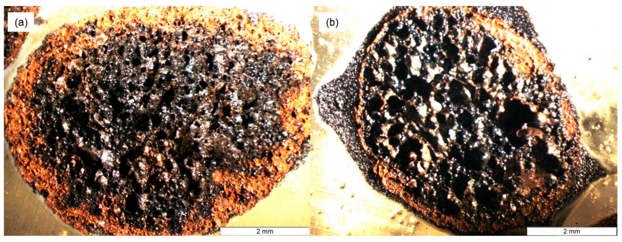
2, 1nh water absorption: 11%, compressive strength: 2.2 Mpa, particle size: 2 to 4 mm. The cross-sectional image of the original porous aggregate is shown in
Figure 3a. The internal pore structure of the aggregate differs from its external surface, both in color and in porosity. Specifically, the inner pores are larger than those on the outer surface. This loose and porous architecture provides sufficient space for loading the modified agar gel. The cross-sectional image of the aggregate after gel loading is presented in
Figure 3b. The ceramsite was able to partially fill the external pores of the aggregate with modified agar gel. However, due to the resolution limitations of optical microscopy, the actual penetration depth of the gel could not be directly observed.
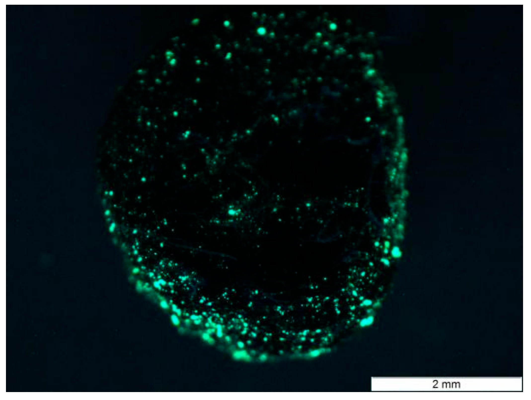
To better visualize the internal loading, a fluorescent resin was introduced into the aggregate, and its distribution was examined under UV light. The results suggest that the modified gel was effectively loaded into the porous ceramsite (see
Figure 4); most of the gel penetrated into the pores located approximately 0.2–0.8 mm beneath the surface, and a small amount of gel was able to reach deeper into the aggregate through interconnected pores. This phenomenon can be attributed to the fact that most of the open, interconnected porosity in the aggregates is concentrated near the surface, as indicated by the friable structure observed under natural light. In contrast, the central region of the aggregate is mostly composed of closed pores, which restrict deeper gel penetration. Although this pore structure limits the overall gel loading capacity, it helps to reduce the bulk density of the material, which can be beneficial for lightweight applications.
The mass and apparent density of the aggregates before and after agar gel loading are shown in
Table 5 and
Table 6, respectively. Based on these data, the mass loading rate and volume loading rate of the modified agar gel in the aggregates were calculated. The mass loading rate (i.e., the percentage of the mass of loaded agar gel relative to the original mass of the empty ceramsite) was calculated using the following formula:
where
w is the mass loading rate of aggregate,
mx is the mass of the loaded aggregate (i.e.,
m1 or
m2), and
m0 is the mass of the empty aggregate. By substituting the values from
Table 5 into Equation (6), the mass loading rates of the modified agar gel in Aggregates 1 and 2 were found to be 36.67% and 44.00%, respectively.
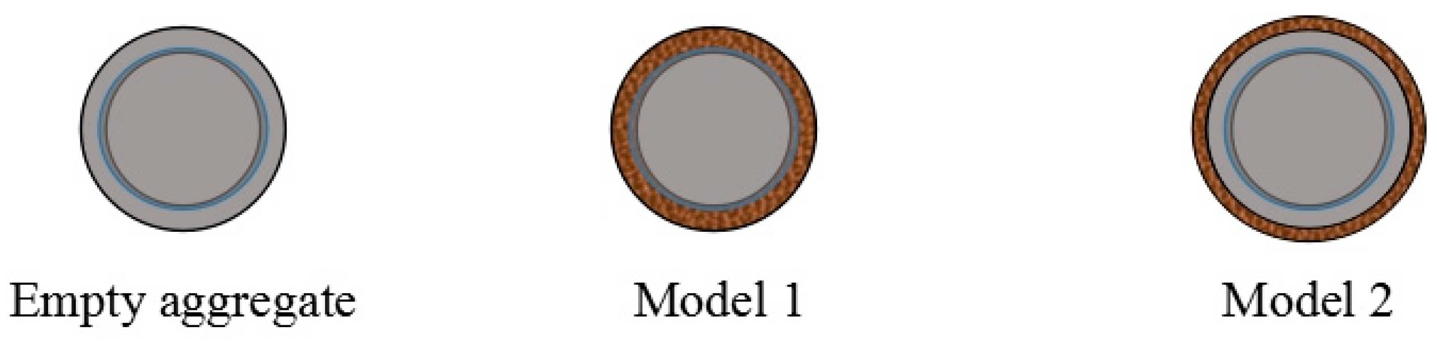
To evaluate the volume loading rate (i.e., the volume fraction of agar gel within the total volume of the loaded aggregate), two simplified models were adopted, as illustrated in
Figure 5.
Model 1 assumes that the modified agar gel entirely enters the interconnected pores of the aggregate. Based on this assumption, the volume loading rate is given by:
Model 2 assumes that the modified agar gel forms a uniform coating on the surface of the aggregate. The corresponding formula is:
where
Vol1 and
Vol2 are the volume loading rates calculated from Model 1 and Model 2, respectively;
V is the loaded agar gel volume (cm
3);
V0 is the apparent volume of the unloaded aggregate (cm
3);
V1 is the total apparent volume after loading (cm
3); and
ρ0 and
ρgel are the apparent densities of the empty aggregate and the agar gel, respectively (see
Table 6). By substituting the values in
Table 5 and
Table 6 into Equations (7) and (8), the volume loading rates of the modified agar gel in Aggregates 1 and 2 were calculated as 27.04% and 27.22%, respectively (for Model 1); 21.28% and 21.40%, respectively (for Model 2).
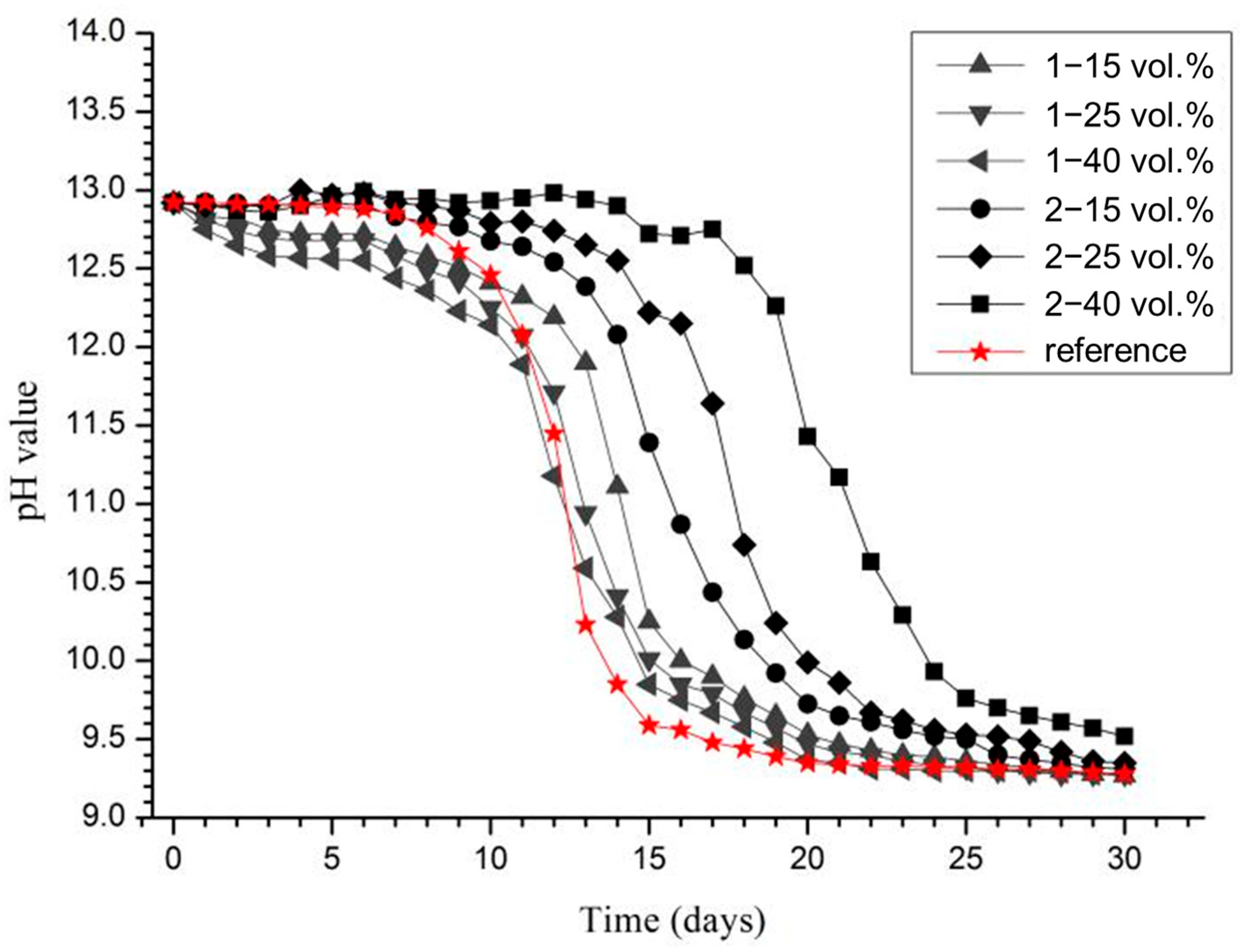
3.2. Effect of Modified Aggregates on the Pore Solution pH
Figure 6 recorded the pH evolution during the ICCP process. For the reference sample without added aggregates, the pH remained stable at approximately 12.90 during the first five days. Starting from day 6, the pH began to decline, and after day 15, it stabilized around 9.4.
With the addition of Aggregate 1, the initial pH was slightly lower than that of the reference, and this trend became more pronounced with increasing volume fractions of the aggregate. This may be attributed to the initial ion exchange or partial dissolution of surface components from Aggregate 1. However, as exposure time increased, the rate of pH decrease was significantly reduced compared to the reference. After day 13, the pH of solutions containing Aggregate 1 remained consistently higher than that of the reference and only dropped to around 9.4 after 20 days. This suggests that although Aggregate 1 did not provide an immediate buffering effect, it effectively slowed the acidification process over time.
In contrast, the addition of Aggregate 2 resulted in a slightly higher initial pH than the reference. Moreover, increasing the volume fraction of Aggregate 2 led to a higher and more sustained pH, remaining above 12 for an extended period. As time progressed, the pH in these solutions declined at a slower rate than in the reference group, maintaining a consistently higher level throughout the test. With Aggregate 2, the pH dropped to 9.4 only after 25 days. These results indicate that the incorporation of functional aggregates helps maintain higher alkalinity near the anode for a longer period, thereby mitigating the acidification-induced degradation during ICCP.
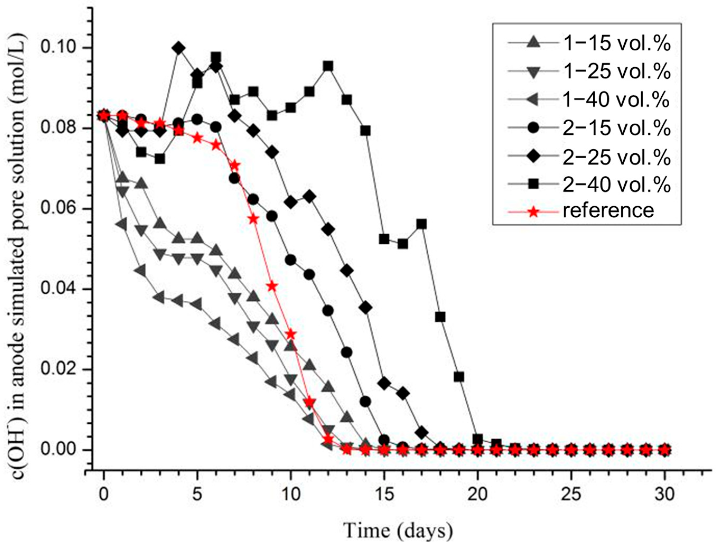
Figure 7 presents the evolution of hydroxide ion concentration c(OH
−) in the anodic pore solution over 30 days, calculated by pH value. With the addition of Aggregate 1, a rapid decline in c(OH
−) was observed in the early stage (0–10 days), primarily because the initial pH of the modified agar gel loaded in Aggregate 1 (12.05) was lower than that of the pore solution (12.92). This pH gradient caused OH
− ions to diffuse into the agar gel within the aggregates.
In contrast, when Aggregate 2 was introduced, c(OH−) initially declined slightly, then increased significantly and remained at a high level for a longer duration, particularly with higher volume fractions. This behavior is attributed to the excess Ca(OH)2 loaded into Aggregate 2. When acidification reduced the OH− concentration in the pore solution below that of the gel in the aggregates, hydroxide ions diffused outward. Additionally, when the solution’s OH− concentration dropped below the solubility of saturated Ca(OH)2, the excess solid Ca(OH)2 gradually dissolved, helping maintain the pore solution pH.
For the reference sample, the OH
− concentration remained stable early on, and began to decrease from day 6 to day 11. In the absence of functional aggregates, this decline followed a nearly linear trend. By fitting the curve, the decrease rate of OH
− concentration during this period was calculated as ν = 0.01305 mol/(L·d). The total OH
− consumption required to reach a low concentration threshold of 0.001 mol/L was then calculated for all systems using Equations (1) and (9), and the results are shown in
Figure 8.
The comparison revealed the cumulative OH− consumption followed the order: 2–40 vol.% > 2–25 vol.% > 2–15 vol.% > 1–15 vol.% > 1–25 vol.% > 1–40 vol.% > Reference. This demonstrates that functional aggregates increase the amount of OH− consumed to reach the same low concentration, thereby enhancing the system’s buffering capacity and effectively prolonging the alkaline condition near the anode. Additionally, Aggregate 2 exhibits a significantly better buffering effect than Aggregate 1.
3.3. Effect of Modified Aggregates on Anode Titanium Mesh in Anode Mortar
The electrochemical impedance spectra of the titanium mesh in anode mortar after different polarization durations are shown in
Figure 9. In the Nyquist plots (
Figure 9a), the x-coordinate of the turning point in the high-frequency region (see enlarged section) corresponds to the bulk resistance of the mortar matrix [
31]. As the polarization time increased, both NAM and CAM specimens exhibited increasing resistance. This trend is attributed to the continued hydration of unreacted cementitious phases (due to the short initial 7-day curing), which led to a denser matrix and subsequently higher resistivity.
At each age, the electrical resistance of CAM was lower than that of NAM. This can be explained by the incorporation of modified aggregates: the Ca(OH)2 embedded in the agar gel inhibited cement hydration, and the electrolytes present in the gel promoted ionic conduction. As a result, the overall compactness of CAM remained lower than NAM during early stages, and the increase in electrical resistance was slower. Notably, while NAM showed continuous resistance growth within the first 28 days of polarization, its resistance significantly decreased after 35 days (even lower than 14 days). This may be due to continuous OH− consumption by anodic reactions under the applied current density, leading to Ca(OH)2 dissolution and increased porosity near the anode. Consequently, the simulated pore solution may have penetrated more deeply into the mortar, decreasing overall resistivity. In contrast, the functional aggregates in CAM helped buffer the pore solution alkalinity, delaying such deterioration.
The Nyquist and Bode plots (
Figure 9) further reveal that both NAM and CAM exhibited relatively small capacitive arc radii and phase angles at day 0, while larger values were observed at days 14, 28, and 35. This indicates a higher corrosion rate of the titanium mesh at early ages, while increased impedance over time suggests reduced anode reactivity due to ongoing hydration and matrix densification. It also suggests that under early-age polarization, continued hydration of unreacted particles in simulated pore solution formed an alkaline environment that was more effective in enhancing anode impedance than the OH
− consumption from anodic reactions.
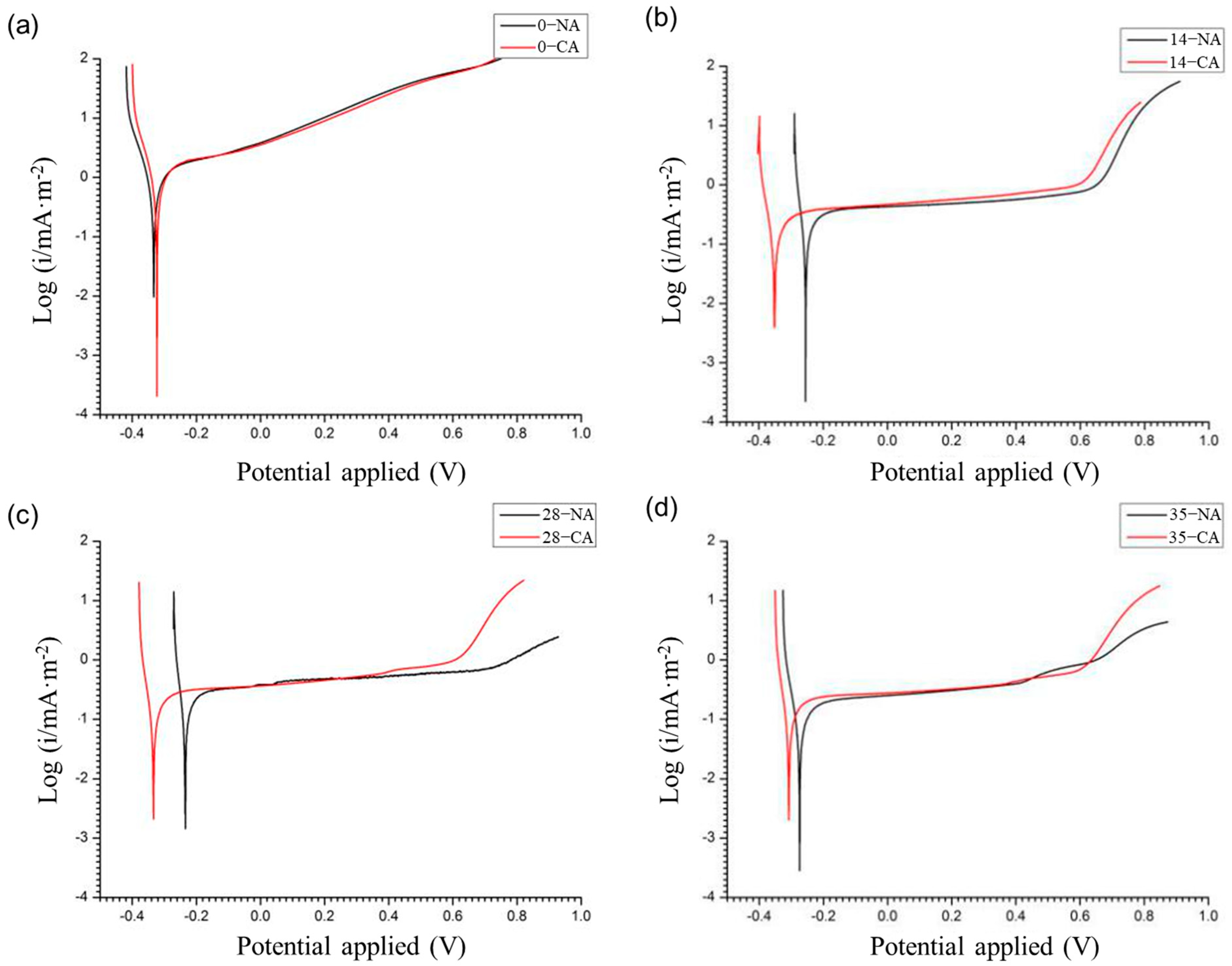
The anodic polarization curves of the titanium mesh under different polarization durations are shown in
Figure 10. The open circuit potential (OCP) of the titanium anode in NAM and CAM at day 0 was similar. However, after 14 days, the corrosion potential of the titanium mesh in CAM became notably more negative than that in NAM. By day 35, the OCP in CAM increased again but remained lower than that in NAM. This indicates a greater corrosion tendency for the titanium mesh in the early, less dense, and oxygen-rich mortar environment compared to later, more compact conditions.
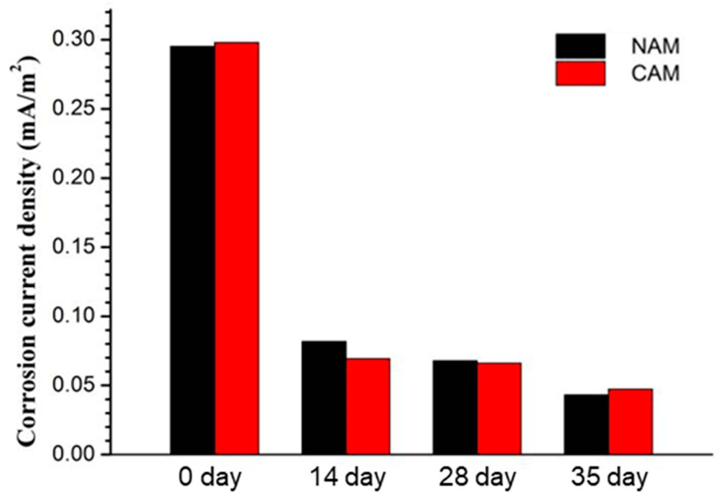
Tafel extrapolation of the titanium mesh anodes in both NAM and CAM at various polarization stages (
Figure 11) revealed little difference in corrosion current density between the two mortars at each age. However, the corrosion current density generally decreased with polarization time and tended to stabilize. This trend suggests that the alkaline environment resulting from post-curing hydration was more effective in suppressing corrosion than the CH consumption caused by anodic polarization at the applied current density (66 mA/m
2). These findings are consistent with the impedance results, as well as the later discussed XRD-based Ca/Si ratio analyses (see
Section 3.4).
3.4. Effect of Modified Aggregates on Hytration Products of Anode Mortar
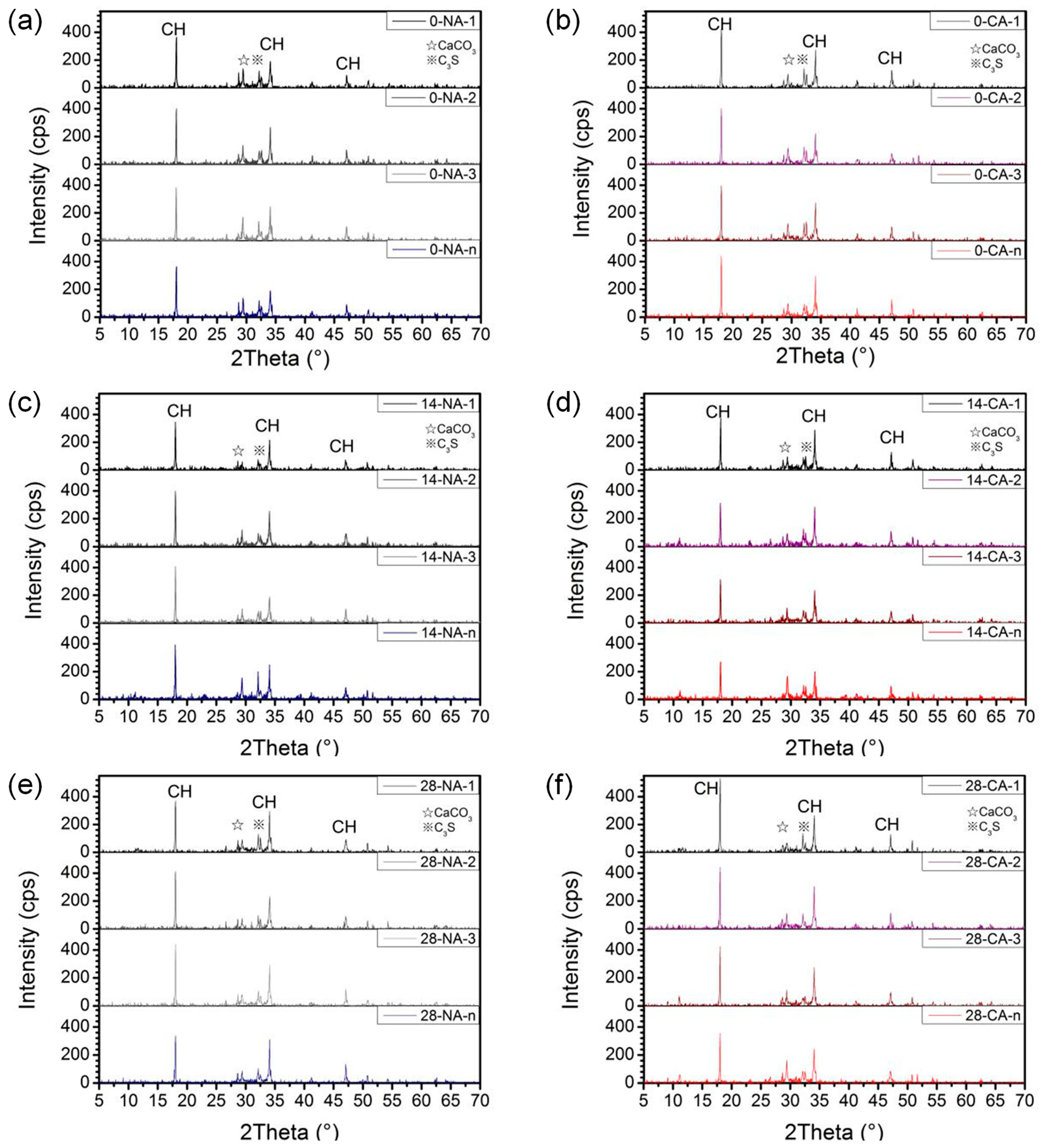
The XRD results of hardened paste samples taken at different ages (0, 14, and 28 days) and distances from the titanium mesh are shown in
Figure 12. The primary crystalline phases identified in the anode mortar include hexagonal Ca(OH)
2, with characteristic peaks corresponding to crystal planes (001), (101), and (102), and d-spacings of approximately 4.92 Å, 2.63 Å, and 1.93 Å, appearing at 2θ values of 17.986°, 34.030°, and 46.988°, respectively. Minor peaks corresponding to orthorhombic CaCO
3 (strongest peak at plane (104), d = 3.035 Å, 2θ = 29.405°) and unhydrated triclinic C
3S (strongest peak at plane (090), d = 2.789 Å, 2θ = 32.066°) were also detected. The mineral phases were identified by matching the diffraction peaks with standard reference patterns from the International Centre for Diffraction Data (ICDD) Powder Diffraction File (PDF) database, specifically using PDF-4+ cards. Portlandite (Ca(OH)
2) was identified with PDF#44-1481, calcite (CaCO
3) with PDF#05-0586, ettringite with PDF#41-1451, and tricalcium silicate (C
3S) with PDF#49-0442. Based on fitted XRD curves, the integrated peak areas of the three strongest Ca(OH)
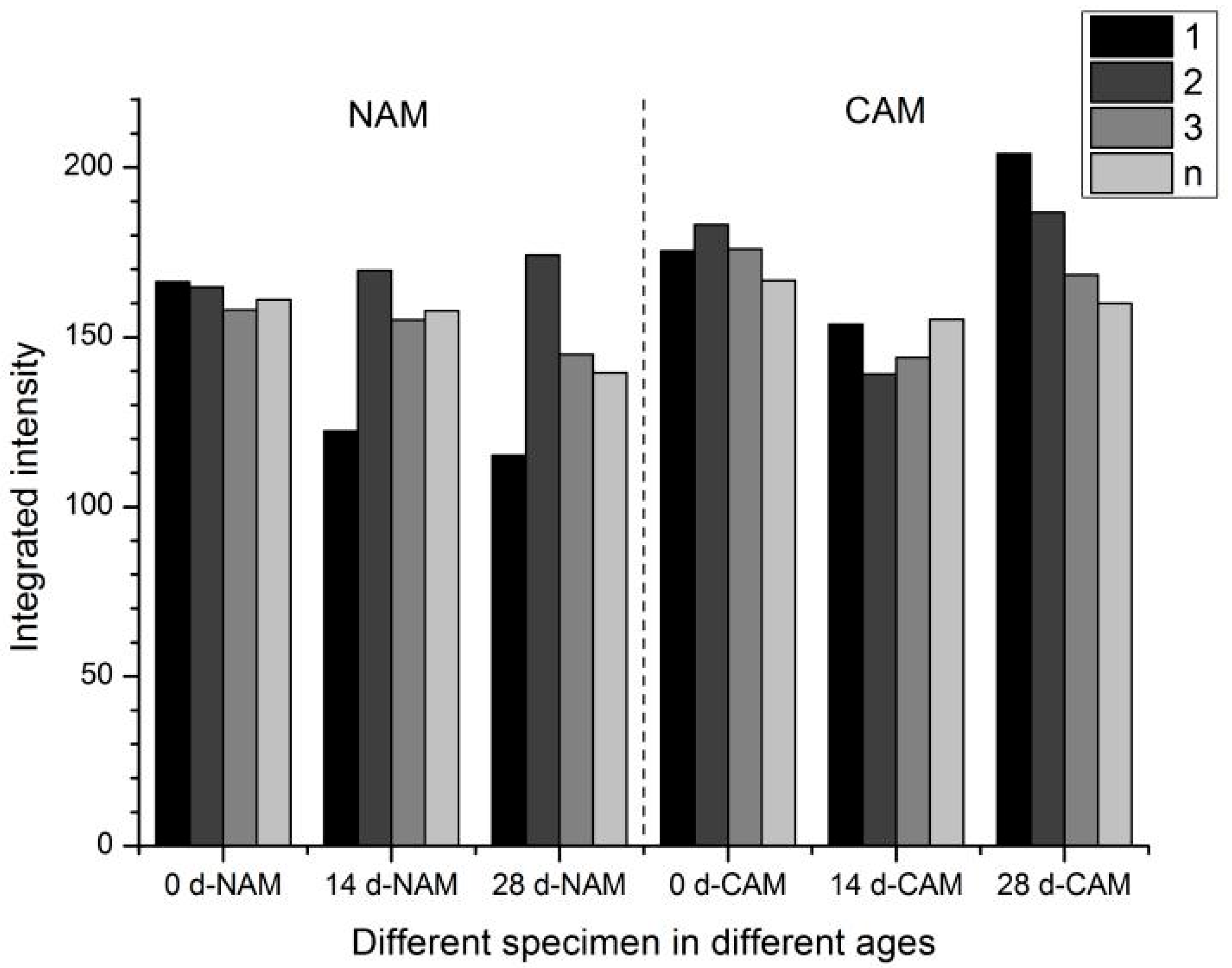
2 (CH) peaks were calculated, as shown in
Figure 13.
As seen in
Figure 13, the overall CH content in NAM and CAM specimens did not significantly change with increased polarization duration, especially in paste layers further from the titanium mesh. This may be attributed to a balance between the consumption of OH
− (due to anodic reactions at the titanium mesh surface leading to CH dissolution) and the continued hydration of unreacted cement particles (given the short initial curing period of only 7 days), which generates additional CH.
Focusing on the layer closest to the titanium mesh (1.0–2.5 mm), the CH peak intensities in NAM and CAM specimens were initially similar. However, by day 28, the CH peak corresponding to the (001) plane (d = 4.92 Å, 2θ = 17.986°) became sharper in CAM, while a decreasing trend was observed in NAM. This suggests a reduction in CH content in NAM due to sustained OH− consumption and CH dissolution near the anode. In CAM, the initially inhibited hydration followed by a pronounced increase in CH crystallinity at later stages may suggest stacking growth of the hexagonal CH (which is known for its easy slippage and may increase paste porosity). The dissolution of CH from within the functional aggregate may also contribute to this phenomenon.
The Ca/Si ratios of hydrated products at different ages and distances from the titanium mesh are shown in
Figure 14. While no significant difference was observed in the Ca/Si ratio between NAM and CAM near the anode, a slight decrease in Ca/Si was noted in the 0–20 μm zone compared to regions more than 30 μm away from the titanium mesh. This may be due to the consumption of OH
− caused by anode polarization, which promotes CH dissolution. However, the more likely cause is the incomplete hydration process due to the relatively short 7-day curing period before testing. It is also acknowledged that some local fluctuations in the Ca/Si ratio appear as irregular peaks, which may seem chaotic. These variations likely arise from inherent heterogeneity in the microstructure at the microprobe scale, combined with minor measurement noise. Based on the resolution and stability of the SEM-EDS system, the amplitude of these peaks does not significantly exceed the expected uncertainty of point analysis.
It is noted that the present study evaluates performance over a 30-day polarization period under simulated pore solution conditions. While such tests provide a controlled environment to assess the early-stage buffering effect of modified aggregates, they cannot fully replicate the complex chemical and physical conditions in actual concrete structures (e.g., variable moisture levels, carbonation, multi-ion interactions). Therefore, further studies involving longer-term exposure and real concrete matrices are needed to verify the long-term applicability of the proposed aggregates in practical ICCP systems.
4. Conclusions
Modified aggregates for mitigating anodic acidification caused by impressed current cathodic protection (ICCP) were successfully prepared by incorporating Ca(OH)2. The effects of the prepared aggregates on anode titanium mesh, pH of pore solution, and anode mortar were investigated. The main conclusions are as follows:
(1) Aggregates loaded with NaOH and corrosion inhibitor (Aggregate 1) and aggregates proposed in this paper (Aggregate 2) were prepared and compared. The mass loading rates were 36.67% and 44.00%, respectively, with volume loading rates ranging between 21% and 28%.
(2) Compared to the NaOH/NaNO2-modified aggregates (Aggregate 1), the Ca(OH)2-modified aggregates proposed in this study (Aggregate 2) exhibit a more sustained buffering effect under anodic polarization. This is attributed to the lower solubility and gradual dissolution behavior of Ca(OH)2, which allows for extended release over time, thereby enhancing the durability of the anode environment. The experimental results confirmed that Ca(OH)2-modified aggregates outperformed the Na-based system in maintaining higher pH levels and delaying acidification-induced degradation, highlighting a key improvement in buffering strategy for ICCP systems.
(3) Compared to ordinary mortars, anode mortars with aggregates proposed in this paper (Aggregate 2) exhibited a slower cement hydration process during ICCP. Under a current density of 66 mA/m2, the incorporation of proposed aggregates demonstrated an inhibitory effect on the acidification-induced degradation of the hardened cement paste within 28 days of polarization, providing a viable material-level strategy for durability enhancement in RC structures toward infrastructure modernization.


