Article

Experimental Investigation on the Mechanical Properties of Geopolymer Recycled Aggregate Concrete Reinforced with Steel-Polypropylene Hybrid Fiber

1
Henan Vocational College of Water Conservancy and Environment, Zhengzhou 450008, China
2
School of Civil Engineering, Architecture and Environment, Hubei University of Technology, Wuhan 430068, China
*
Author to whom correspondence should be addressed.
Buildings 2025, 15(10), 1723; https://doi.org/10.3390/buildings15101723
Submission received: 23 April 2025 / Revised: 15 May 2025 / Accepted: 15 May 2025 / Published: 19 May 2025
(This article belongs to the Section Building Materials, and Repair & Renovation)

Abstract

:
Geopolymer recycled aggregate concrete (GRAC) is an eco-friendly material utilizing industrial byproducts (slag, fly ash) and substituting natural aggregates with recycled aggregates (RA). Incorporating steel-polypropylene hybrid fibers into GRAC to produce hybrid-fiber-reinforced geopolymer recycled aggregate concrete (HFRGRAC) can bridge cracks across multi-scales and multi-levels to synergistically improve its mechanical properties. This paper aims to investigate the mechanical properties of HFRGRAC with the parameters of steel fiber (SF) volume fraction (0%, 0.5%, 1%, 1.5%) and aspect ratio (40, 60, 80), polypropylene fiber (PF) volume fraction (0%, 0.05%, 0.1%, 0.15%), and RA substitution rate (0%, 25%, 50%, 75%, 100%) considered. Twenty groups of HFRGRAC specimens were designed and fabricated to evaluate the compressive splitting tensile strengths and flexural behavior emphasizing failure pattern, load–deflection curve, and toughness. The results indicated that adding SF enhances the specimen ductility, mechanical strength, and flexural toughness, with improvements proportional to SF content and aspect ratio. In contrast, a higher percentage of RA substitution increased fine cracks and reduced mechanical performance. Moreover, the inclusion of PF causes cracks to exhibit a jagged profile while slightly improving the concrete strength. The significant synergistic effect of SF and PF on mechanical properties of GRAC is observed, with SF playing a dominant role due to its high elasticity and crack-bridging capacity. However, the hydrophilic nature of SF combined with the hydrophobic property of PF weakens the bonding of the fiber–matrix interface, which degrades the concrete mechanical properties to some extent.

1. Introduction

Geopolymer recycled aggregate concrete (GRAC) is a novel construction material produced by replacing ordinary Portland cement with industrial byproducts (e.g., fly ash, slag, silica fume) and natural aggregates (NA) with recycled aggregates (RA). It offers significant advantages in excellent mechanical properties and durability, reducing carbon emissions, enhancing eco-friendliness, and promoting sustainability [1,2,3], aligning with “Dual Carbon” and sustainable development strategies. However, like conventional concrete, GRAC exhibits inherent brittleness and poor ductility, which hinder its practical engineering applications [4,5]. In recent decades, fiber reinforcement has been a widely used method to improve the toughness of concrete, namely, fiber-reinforced concrete (FRC) [6,7,8]. Nevertheless, concrete cracking is a multi-scale and multi-level process. Single-type fiber primarily improves the mechanical properties of concrete at specific scales, exerting limited influence at other levels [9]. Consequently, hybrid fiber reinforcement, combining fibers of various scales, e.g., macro steel fiber (SF) and micro polypropylene fiber (PF), has emerged as a promising strategy to develop hybrid-fiber-reinforced geopolymer recycled aggregate concrete (HFRGRAC), thereby enhancing its performance across multiple scales comprehensively [10].
To facilitate the engineering application of GRAC materials, considerable efforts have been made to investigate their mechanical properties, which have yielded important outcomes. Previous studies [2] have shown that GRAC reduces the carbon emission of concrete production by over 50% compared to conventional plain concrete at an equivalent strength level. Notably, GRAC with 75% RA replacement achieves comparable compressive strength to that of plain concrete [10,11,12,13,14,15]. The alkali-activated binders produce a denser interfacial transition zone (ITZ) between RA and matrix than those in ordinary cement-based systems due to the second hydration of cement and fly ash particles in old mortar layers in RA, thereby mitigating the adverse effect of RA incorporation [13,16,17,18]. The compatibility between RA and alkali-activated binders enhances the engineering feasibility of GRAC materials and structures. Moreover, empirical models for predicting the mechanical strength, elastic modulus, and uniaxial compressive response of GRAC have been established [19,20,21,22]. However, under identical water-to-binder (w/b) ratios, geopolymer concrete exhibits higher strength but greater brittleness compared to ordinary cement-based concrete [4].
To address this issue, researchers have incorporated fibers into geopolymer concrete (GC) and then evaluated the effect of fiber type, volume fraction, and aspect ratio on its mechanical performance [23,24,25,26]. Experimental results indicate that fibers interact more effectively with alkali-activated binders [9], thereby significantly improving the failure modes, tensile strength, cracking resistance, and ductility of GC compared to cement-based systems [24]. Similarly, hybrid fiber systems demonstrate superior synergistic effect in enhancing the mechanical properties of GC relative to single-fiber reinforcements [25,26]. Zhou et al. [27] investigated the mechanical properties and microstructures of fiber-reinforced mortar–limestone composites and observed that fibers tend to weaken the fracture properties of aggregate matrix ITZs. Single reinforcements with SF or PF exhibit more pronounced weakening than hybrid fiber systems. With respect to GRAC, Zhao et al. [28] investigated the mechanical properties of SFRGRAC and demonstrated that adding fibers mitigates the performance degradation such as strength loss, abrasion, and reduced thermal and freeze–thaw resistance induced by RA incorporation. Li et al. [29] conducted uniaxial compression tests on the stress–strain behavior of SFRGRAC and found that the incorporation of SF enhances the mechanical performance of GRAC due to its fiber crack-bridging role and adaptation of SF in the GC matrix. Based on the test results, uniaxial compressive constitutive models based on macro test data were established [30,31,32]. These findings provide a theoretical foundation for the practical implementation of GRAC.
In summary, although existing studies have advanced to the understanding of GRAC and single-fiber-reinforced GRAC (e.g., SFRGRAC), research on HFRGRAC remains scarce, especially concerning the synergistic enhancement mechanisms of steel-polypropylene hybrid fibers across multiple scales. The mechanical property evolution of GRAC with different hybrid fiber factors is unclear, as well as the fiber reinforced mechanism. To address this gap, the present study conducted mechanical tests on 20 groups of HFRGRAC specimens. The effect of SF volume fraction and aspect ratio, PF volume fraction, and RA substitution rate on compressive strength, splitting tensile strength, and flexural behavior (cracking patterns, flexural strength, deflection, and toughness) was analyzed. Moreover, scanning electron microscopy (SEM) was used to observe the interfacial transition zone between the fibers, aggregates, and matrix. Combined with macroscopic mechanical testing, this further elucidates the failure mechanism of HFRGRAC, providing theoretical guidance for the engineering applications of HFRGRAC materials and structures.

2. Materials and Methods

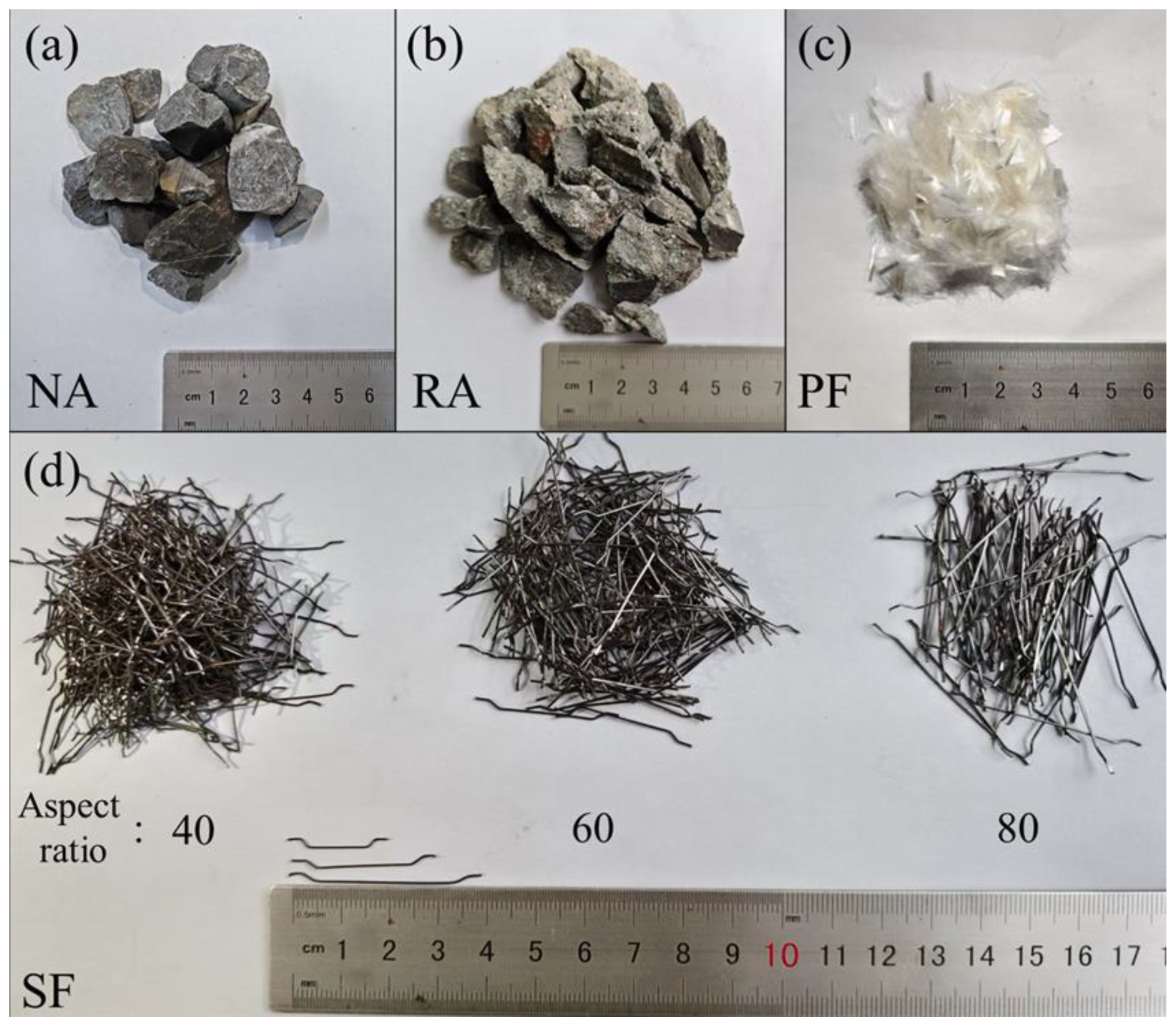
2.1. Materials and Mix Proportions

The binder materials for HFRGRAC consisted of ground granulated blast furnace slag (GGBS) and I-fly ash (FA) (Lingshou County Qiangdong Mineral Products Processing Factory, Shijiazhuang, China), with their chemical compositions provided in Table 1. The alkali activator was formulated by mixing sodium silicate (Na2SiO3) solution (modulus = 3.3, containing 27.3% SiO2 and 8.5% Na2O by mass, Wuhan Jiye Shenghua Co., Ltd., Wuhan, China) with flake sodium hydroxide (purity ≥ 96%, 0.36 mol/dm3, Gongyi Yurun Haiyuan Water Purification Materials Co., Ltd., Gongyi, China). It has been observed that, when the modulus of the activator exceeds the range of 0.5 to 2.0, the workability and mechanical properties of geopolymer concrete significantly decrease [33]. Therefore, based on previous experiments [4], the final modulus of the alkali activator was selected as 1.2. The fine aggregate was natural river sand with a fineness modulus of 2.6 and particle size of 0.5–5 mm. The coarse aggregate (CA) included NA and RA (Wuhan Longchangrui Building Materials Co., Ltd., Wuhan, China), as shown in Figure 1. NA was locally sourced crushed basalt with a maximum particle size of 20 mm and RA was processed from demolished C40-grade concrete. The basic properties of NA and RA are listed in Table 2. A powdered naphthalene-based superplasticizer with a water reduction rate of 18–25% was employed to adjust the fresh state of GRAC mixtures. In addition, hooked-end SF (Anping County Zhihui Engineering Materials Co., Ltd., Hengshui, China) and monofilament PF (Shandong Huayao Rubber and Plastic Co., Ltd., Jinan, China) were employed as shown in Figure 1. This is due to the complementary effect of them, where SF provides effective crack bridging through mechanical anchoring within macrocracks, while PF suppresses the formation of micro cracks [32,34]. Their key properties are provided in Table 3.
Chachar et al. [35] reported that, when the SF content exceeds 1.5%, the workability of concrete decreases significantly. Additionally, in conjunction with Li et al.’s [34] research on the effect of SF aspect ratios (40, 60, 80) on mechanical properties, the variation ranges for both SF content and aspect ratio were determined. The PF content range (0–0.15%) was determined through preliminary experiments, confirming that this range enhances crack resistance without causing workability deterioration due to fiber agglomeration. Furthermore, the RA substitution rate was set to a 25% arithmetic gradient to systematically characterize the transitional behavior of the material’s performance. To evaluate the effect of hybrid fiber and RA parameters on the mechanical performance of GRAC, four experimental variables were selected based on prior research and relevant standards [4,22,29,34,35], and are given as SF volume fraction (0%, 0.5%, 1.0%, 1.5%), SF aspect ratio (40, 60, 80), PF volume fraction (0%, 0.05%, 0.1%, 0.15%), and RA replacement rate (0%, 25%, 50%, 75%, 100%). A total of 20 groups of mixtures were designed, as presented in Table 4.

2.2. Specimen Preparation

The specimen design and preparation were in accordance with the Chinese standard GB/T 50081-2019 [36]. For each mixture, six 100 mm cubic specimens were cast for compressive and splitting tensile strength tests, along with three prismatic specimens (100 × 100 × 400 mm3) for the four-point bending test. The specimen preparation process was conducted as follows: GGBS, FA, fine aggregates, coarse aggregates, and SF were first dry-mixed for 5 min. Then, the water activator solution was added and the mixture was wet-mixed for 3 min. The pre-dispersed PFs were subsequently incorporated until the mixture was homogenized. Finally, the fresh concrete was vibrated into molds and sealed with plastic film in the laboratory at 20 ± 5 °C and 65% RH for 24 h before demolding. After demolding, specimens were stored at 20 ± 2 °C and over 95% RH until testing. It should be noted that the alkali activator solution should be prepared 24 h before casting to dissipate the exothermic heat generated by NaOH hydration.

2.3. Test Methods

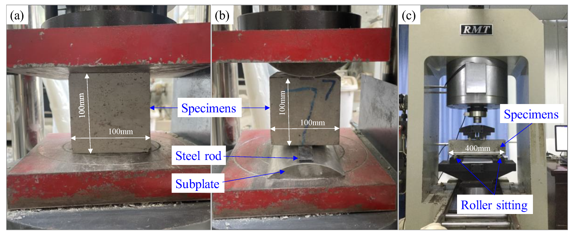
2.3.1. Compressive and Splitting Tensile Strength Test

The experiments of basic mechanical strengths and flexural behavior measurement were conducted following the Chinese recommendation GB/T 50081-2019 [36], as exhibited in Figure 2. A 300-ton servo-controlled testing machine was used to measure the compressive and splitting tensile strengths of HFRGRAC, with the loading rates of 0.5–0.8 MPa/s and 0.05–0.08 MPa/s, respectively. The average results are documented in Table 3.

2.3.2. Four-Point Bending Test

Four-point bending tests were executed on 100 × 100 × 400 mm3 prisms using a computer-controlled RMT-301 test frame, as shown in Figure 2c. The testing regime comprised pre-conditioning and monotonic loading. Firstly, 10% ultimate load application (5 kN/min) was employed to ensure specimen–machine conformity, and then a 0.12 mm/min displacement rate was performed until fracture [37]. Triplicate specimens per mixture underwent testing under ambient conditions (23 ± 2 °C, 60 ± 5% RH).

2.3.3. Microstructure Characterization Method

In order to ascertain the failure mechanism of HFRGRAC, the microstructures of samples at 28 days were captured using field-emission SEM (Hitachi SU8010, 5 kV accelerating voltage, Wuhan Yide (Branch) Direct Reading Spectrometer|Handheld Spectrometer, Wuhan, China) under high vacuum (5 × 10⁻⁴ Pa), especially for the CA matrix and fiber matrix ITZs. The samples were firstly mounted on conductive holders with carbon adhesive tabs, and then they were sputter-coated for a 15 nm thickness. Secondary electron imaging was at an 8.5 mm working distance with 50,000× maximum magnification.

3. Experimental Results and Discussion

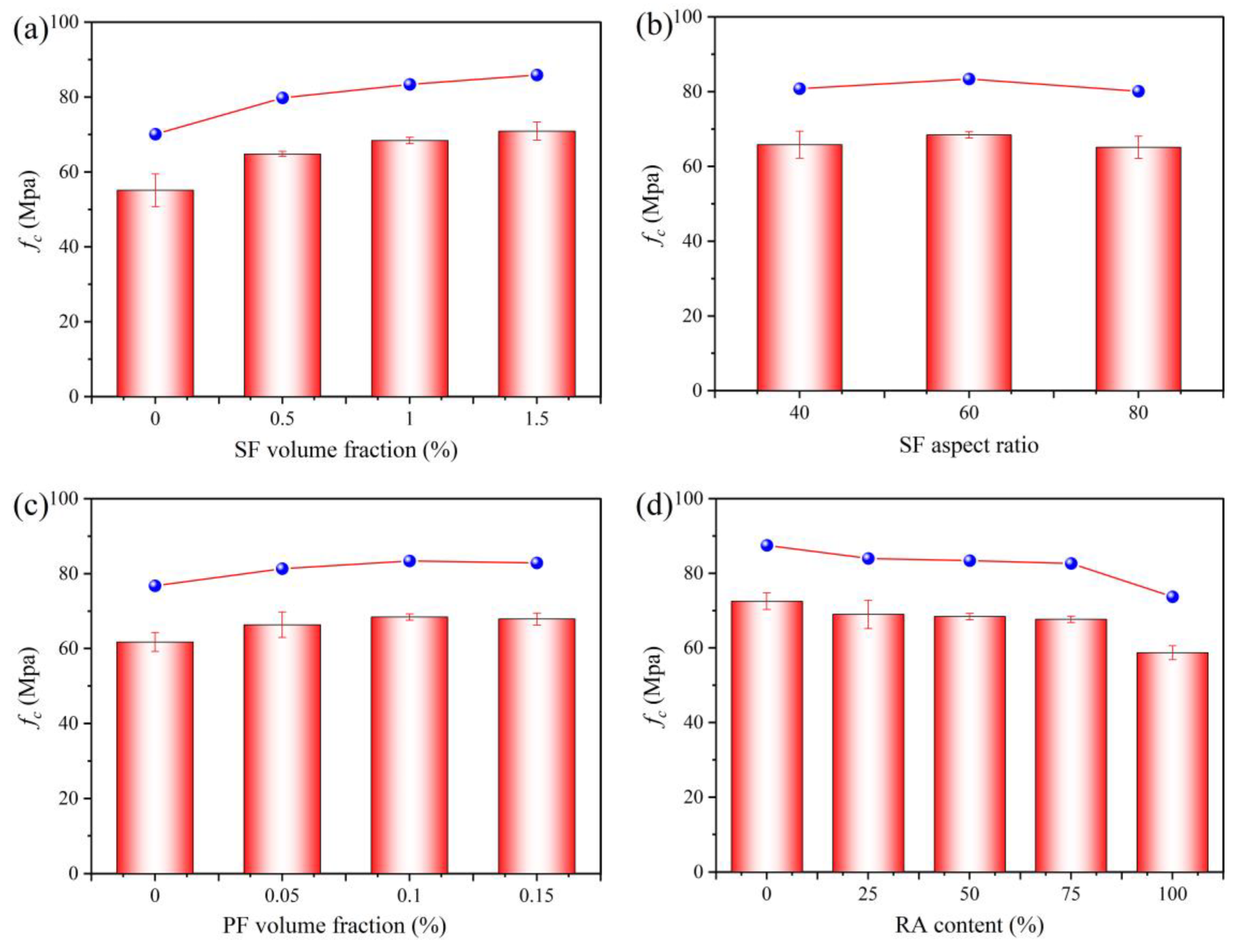
3.1. Compressive Strength

The results of the compressive strength of HFRGRAC averaged by a group of three are illustrated in Figure 3. It can be seen that, as the SF content rises from 0% to 1.5%, the compressive strength of GRAC increases by 17.57%, 24.10%, and 28.64%, respectively, due to the fiber crack-bridging effect [7], in spite of the gradually decreased increasing rate. This phenomenon is primarily attributed to the hydrophilic nature of SF, which results in a slightly higher w/b ratio at the SF–matrix interfaces than in the matrix, thereby forming weak interfacial zones [38]. This interfacial defect can reduce the reinforcing effect of the fibers. Although SF has a high elastic modulus and crack-bridging capability, the additional porosity caused by interface defects significantly reduces the potential for strength improvement.
Figure 3b demonstrates the effect of SF aspect ratio on the compressive strength of GRAC. It can be seen that HFRGRAC achieves the maximum compressive strength at an SF aspect ratio of 60, although the differences across various aspect ratios are minimal. This limited effect may be owing to the fact that the fiber crack-bridging capacity is predominantly governed by a combined influence of fiber quantity at cracks and fiber–matrix bonding area [32]. When the SF aspect ratio fluctuates within a specific range, its variation exerts a minimal impact on the coupling mechanism and, thus, on the compressive strength of GRAC.
Figure 3c presents the compressive strengths of HFRGRAC with varying PF contents. Generally, incorporating PF moderately enhances the compressive strength, with the maximum improvement of 10.76%. However, increasing the PF content from 0.1% to 0.15% results in a 0.76% reduction in the strength, which may originate from the dual effect of PF [39]. Typically, at low PF content, PF could suppress the micro crack initiation and propagation, whereas, once at excessive contents, weak hydrophobic interfaces and poor dispersion would be introduced [37], ultimately degrading the microstructural integrity.
Figure 3d reveals the influence of RA content on the compressive strength of HFRGRAC. It is found that the compressive strength exhibits an overall declining trend with increasing RA content, reaching the maximum reduction of 21.21%, which mainly resulted from the inferior mechanical properties of RA matrix ITZ compared to NA matrix ITZ [4]. However, it should be noted that the reaction between unhydrated binder particles such as cement and fly ash in RA old mortar and alkali activators generates pore-filling products that compensate for initial defects in RA, as confirmed by other researchers [3,10,11,12,13,14]. This compensatory mechanism can explain why GRAC exhibits an insignificant reduction in compressive strength when RA content remains below 75%. When beyond a 75% RA replacement level, a marked 13.23% decrease in strength occurs, as the weakening effect of RA matrix ITZ overwhelms the beneficial contribution of alkali activation.

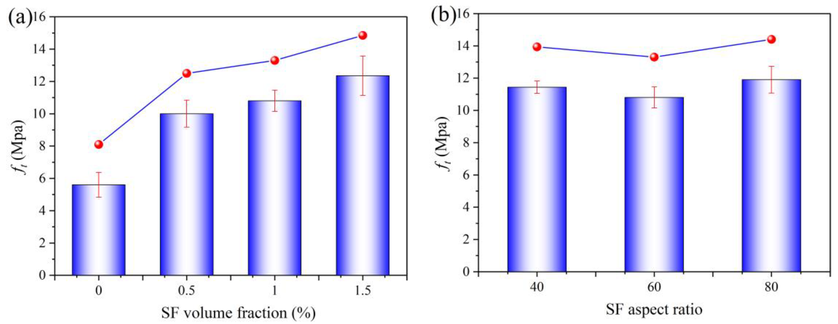
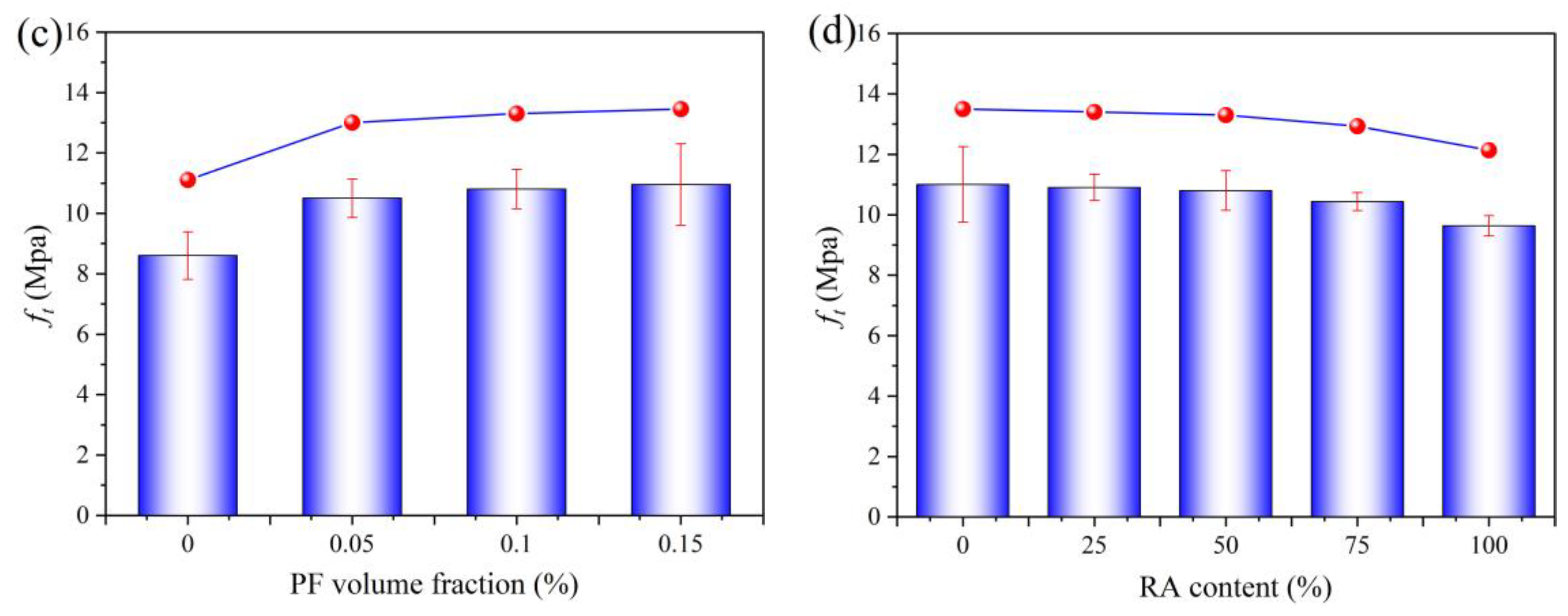
3.2. Splitting Tensile Strength

The splitting tensile strength of HFRGRAC under different fiber parameters and RA content is illustrated in Figure 4. Overall, the variation trend of splitting tensile strength is consistent with that of compressive strength. As shown in Figure 4a, as the SF volume content increases from 0% to 1.5%, and the tensile strength of GRAC increases by 78.75%, 92.86%, and 121.61%, respectively, relative to SB00P10-50, which indicates a significantly greater enhancement effect of SF content on tensile strength than compressive strength. This phenomenon is attributed to the fact that crack propagation under tension depends more strongly on the fiber-bridging effect [34]. The high ductility of SF effectively delays the stress concentration at crack tips and retards its further development, thereby substantially enhancing tensile performance. As expected, the influence of SF aspect ratio on the splitting tensile strength of GRAC also follows a similar trend to that of compressive strength, as shown in Figure 4b.
Figure 4c shows the role of PF content on the splitting tensile strength of HFRGRAC for fixed SF content and aspect ratio. When the PF content is 0.05%, 0.1%, and 0.15%, the splitting tensile strength increases by 24.53%, 25.58%, and 33.95%, correspondingly, compared to SB10P00-50. Notably, PF exhibits a significantly greater enhancement effect on tensile strength (up to 33.95%) compared to compressive strength. The three-dimensional random distribution of PF can form a spatially constrained network to efficiently inhibit the micro crack propagation under tensile loading. However, when the PF content exceeds 0.15%, fiber agglomeration may induce localized stress concentrations, leading to a strength degradation, similar to the negative effect observed on compressive strength at high PF fractions.
Due to the lower elastic stiffness of RA than NA, the incorporation of RA decreases the splitting tensile strength of GRAC, as illustrated in Figure 4d. As RA content increases from 0% to 100%, the split tensile strength decreases by 1.09%, 2.00%, 5.63%, and 12.61%, respectively. Notably, the strength reduction remains marginal at RA content below 50%, but accelerates markedly as the RA content continues to increase, which is primarily accounted for by inherent defects of RA matrix ITZs. Increased RA content elevates crack density and porosity due to residual old mortar layers, thereby accelerating the coalescence of primary cracks [17]. This finding is consistent with previous studies [22], where, when RA content exceeds a critical threshold of about 50%, the connectivity of weak ITZ regions intensifies, resulting in an accelerated deterioration of tensile strength.

3.3. Flexural Behavior

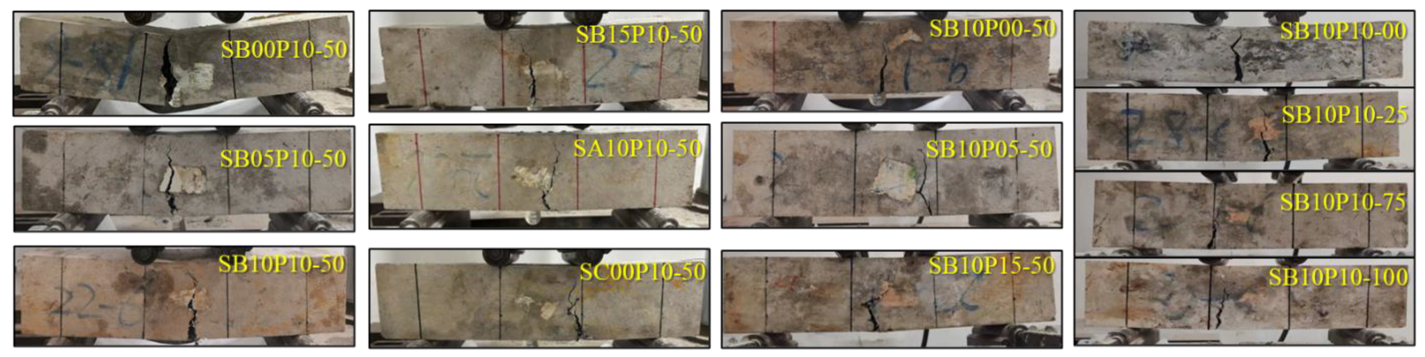
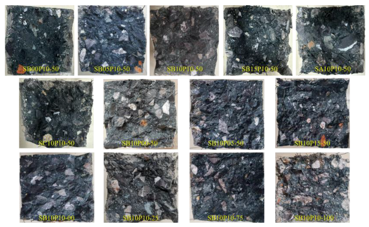
3.3.1. Flexural Process and Failure Modes

The typical failure modes of HFRGRAC beams under four-point bending are shown in Figure 5 and Figure 6. Comparative analysis reveals that specimens without SF addition undergo instantaneous brittle fracture upon reaching the ultimate load, characterized by smooth fracture surfaces. In contrast, specimens reinforced with SF demonstrate pronounced ductile failure characteristics due to the fiber-bridging effect, showing that the primary crack propagation path deflects, accompanied by a secondary crack initiation. This phenomenon becomes increasingly prominent as the SF content increases. Notably, specimens with different SF aspect ratios exhibit similar failure patterns, which are consistent with their mechanical performance trends.
The influence of RA content manifests as a progressive evolution of fracture surface. As RA substitution rate ranges from 0% to 100%, the fracture surface transitions from a smooth continuous form to a discontinuous wavy configuration. This morphological transformation directly correlates with the weak RA matrix ITZ characteristics, wherein pre-existing micro-defect networks induced by residual old mortar layers preferentially coalesce under flexure and, as a result, form complex and multi-scale crack propagation paths [7]. Similarly, increasing PF content transforms fracture surfaces from smooth curvilinear profiles to serrated morphologies. This effect is attributable to modified crack tip stress fields resulting from the random distribution of PFs, which enhances energy dissipation via fiber pull-out and rupture mechanisms.
From the above analysis, it can be seen that, due to the slip and pull-out of SF, the failure modes of HFRGRAC predominantly follow shear failure mechanisms with marked ductile characteristics [34]. Specifically, SF volume fraction governs failure progression through crack path redirection and the modulation of secondary crack density, while RA and PF contents primarily dictate the fracture surface morphology by modifying the internal defect distribution and fracture energy dissipation mechanisms.

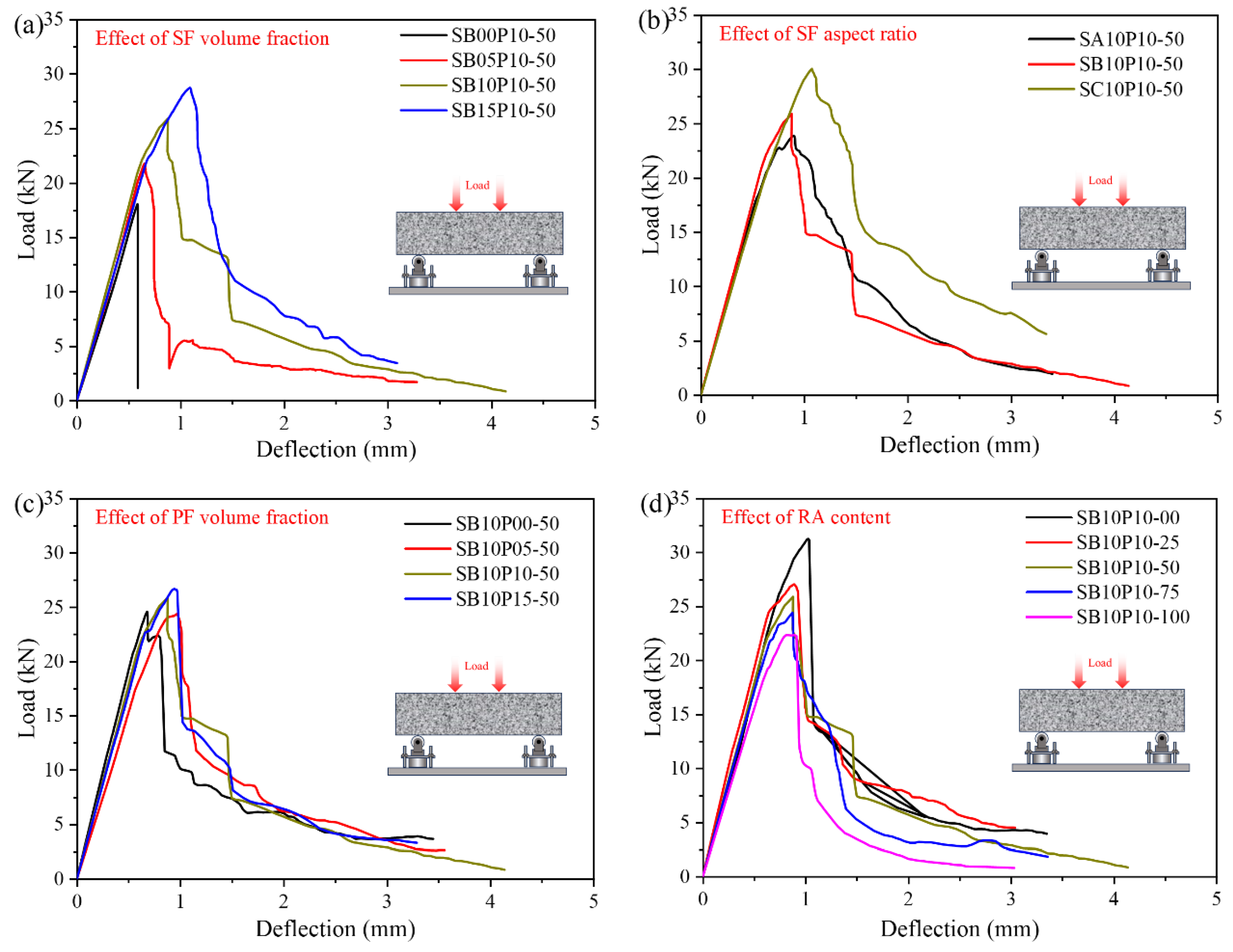
3.3.2. Load–Deflection Curve

The flexural load–deflection curves of HFRGRAC obtained from standard four-point bending tests are plotted in Figure 7. Each curve represents the average of three obtained curves. The key flexural performance parameters including peak load, peak deflection, residual load, and corresponding toughness are summarized in Table 5. According to ASTM C1609/C1609M–2012 [40], the residual loads PL300, PL150, and PL100 correspond to loads measured at deflections of 1, 2, and 3 mm, respectively. Three flexural toughness indices, ΩL300, ΩL150, and ΩL100, are defined as the integral areas under the load–deflection curve up to deflections corresponding to the various residual loads. The peak flexural strength can be calculated using Equation (1) according to the Chinese code GB/T 50081-2019 [36]. The calculated results are presented in Table 5.
f p e a k = P p e a k L b h 2
where, Ppeak denotes the peak load in kN. L represents the span length in 300 mm. b and h correspond to the length and height of specimen cross-section, both in 100 mm.
As illustrated in Figure 7, the curves generally exhibit four evolutionary stages: elastic stage, deflection-hardening stage, deflection-softening stage, and stabilization stage, which is consistent with cement-based HFRC [34,37]. Figure 7a reveals that specimens without SF undergo a direct transition from elastic stage to failure stage immediately after the elastic phase, exhibiting notably brittle fracture behavior. In contrast, SF-reinforced specimens display a complete four-stage curve morphology, with peak load enhancements ranging from 20.85% to 59.44% and increased residual deflection, indicating significant ductility improvement. This case is mainly attributed to the effective retardation of crack propagation by SF through fiber pull-out, slip friction, and deformation during flexure. As the SF dosage increases to 1.5%, the fiber–matrix interface contact area exhibits a linear growth, thereby enhancing the energy dissipation capacity of SF bridges and simultaneously improving both the peak load and deflection.
The impact of SF aspect ratio on the load–deflection curves of GRAC follows a similar pattern, as shown in Figure 7b. The peak load is improved by 8.49–25.78% as the SF aspect ratio rises from 40 to 80, respectively. Notably, although variations in SF aspect ratio simultaneously affect the effective anchorage length and critical pull-out stress of fibers, their combined effect maintains strengthening mechanisms analogous to those observed with changes in volume fraction due to compensatory energy dissipation.
PF content demonstrates differential influences on the load–deflection curves of GRAC, as shown in Figure 7c. While an increment in PF content from 0% to 0.15% achieves peak load improvements of 0.75–9.41%, its strengthening efficiency represents only 8.83–36.50% of that of SF. This discrepancy originates from distinct mechanisms: low-elastic-modulus PF primarily inhibits micro crack initiation and propagation through its three-dimensional spatial confinement networks, whereas high-modulus SF directly bears tensile stresses through superior stress transfer efficiency.
The impact of RA content predominantly manifests in post-peak curve characteristics (seen in Figure 7d). As RA content changes from 0% to 100%, the peak load decreases by 13.50–28.64%, which is correlated with the defect density in RA matrix ITZs. Specifically, the adhered old mortar layer in RA significantly increases the ITZ porosity [16], thereby enabling localized damage accumulation at lower stress levels and the premature triggering of the strengthening stage.

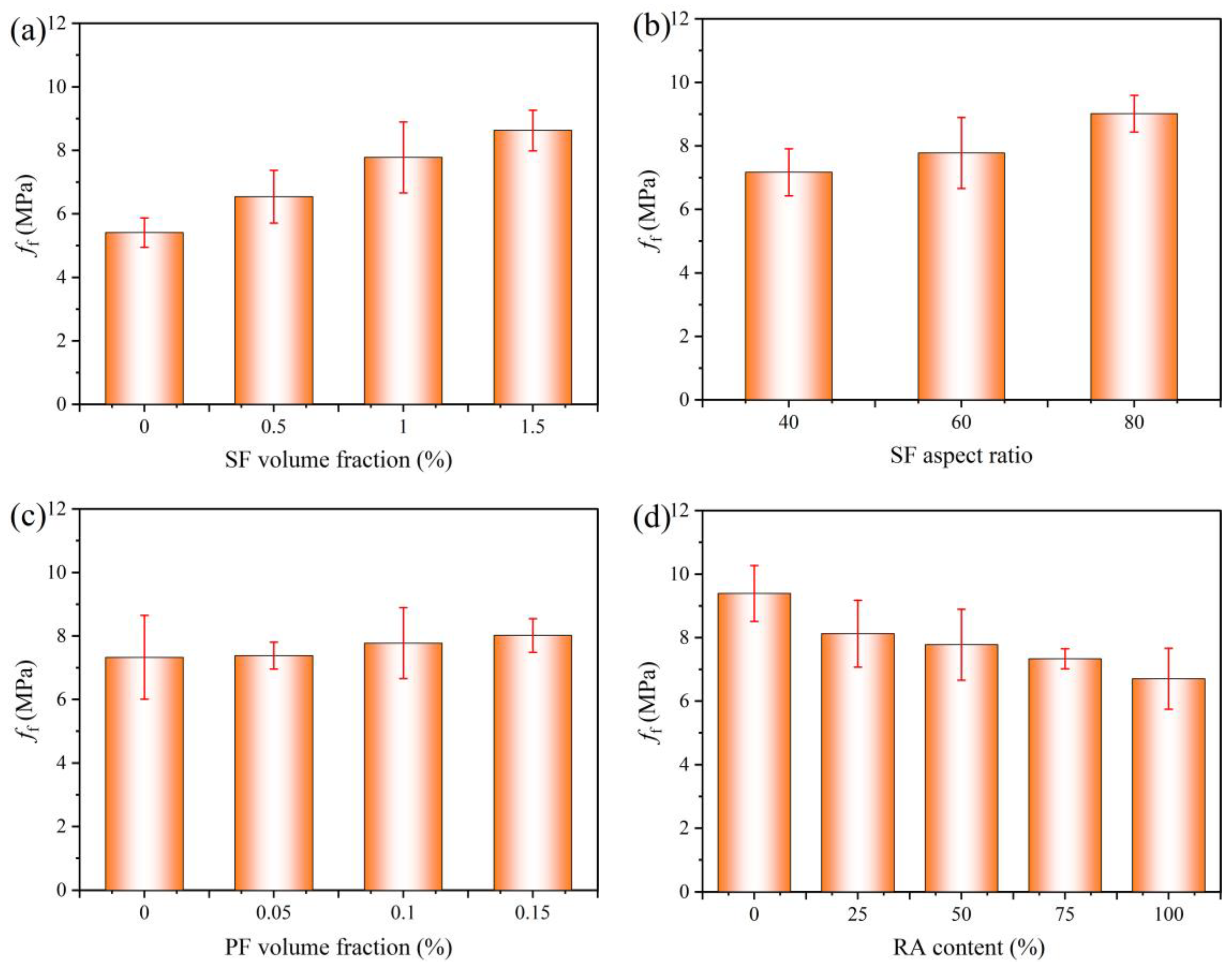
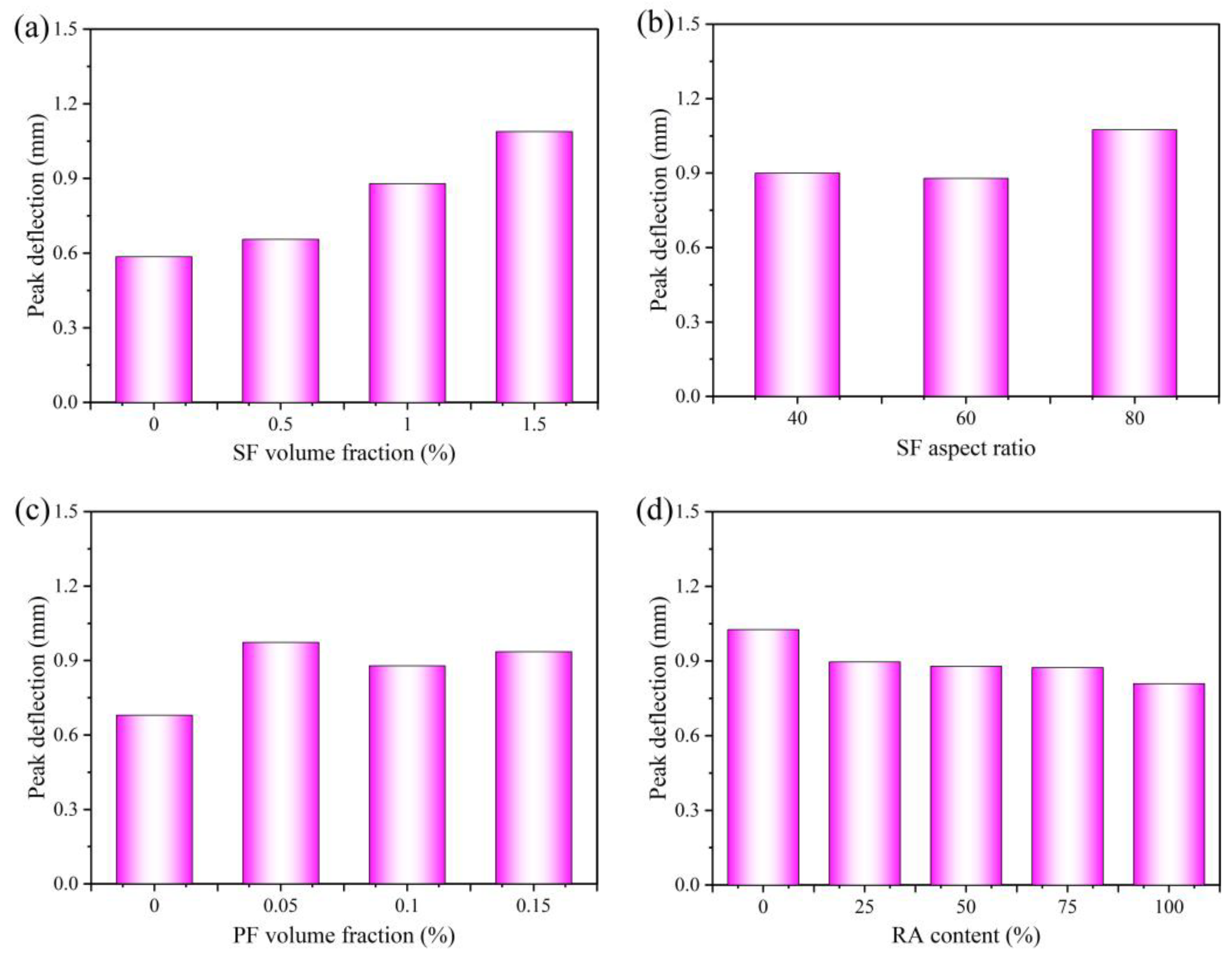
3.3.3. Load and Deflection Characteristics
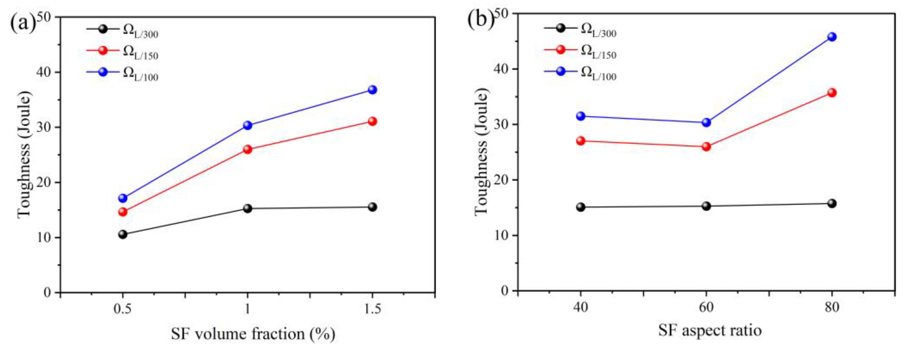
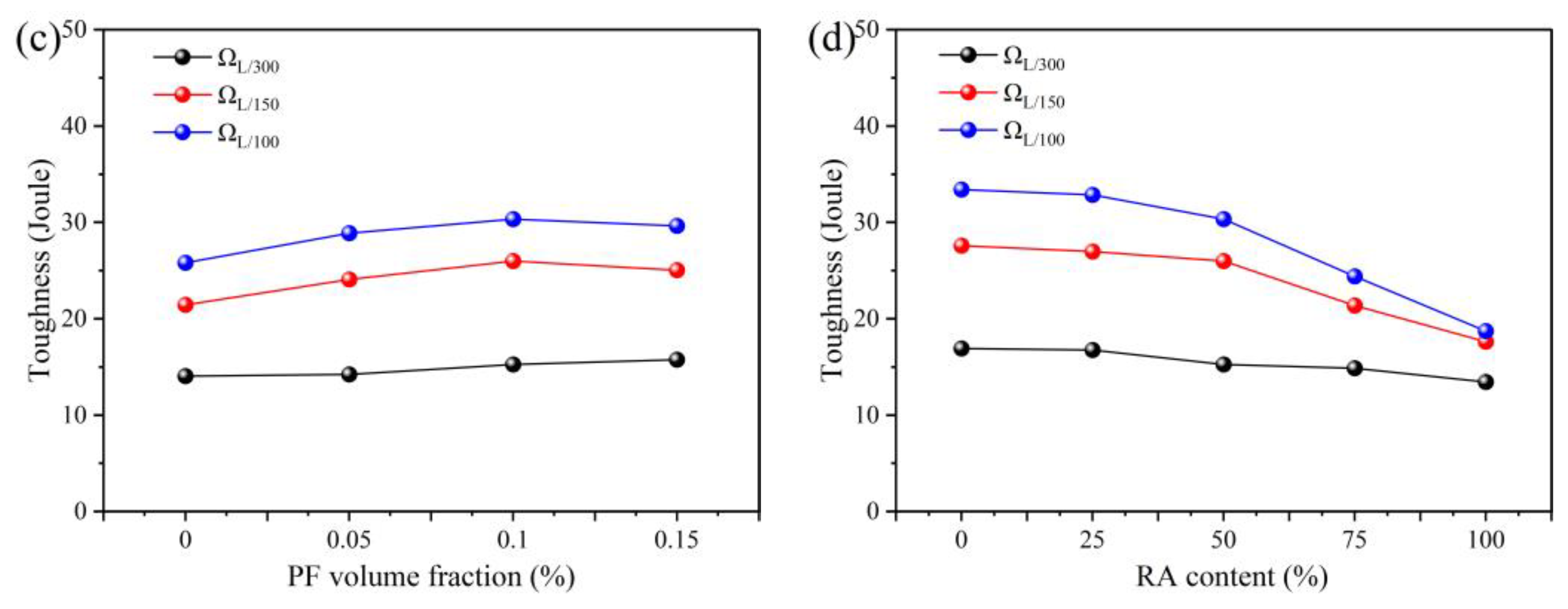
The influence of key parameters on the flexural properties of HFRGRAC is illustrated in Figure 8 and Figure 9. The results demonstrate that SF volume fraction is significantly and positively correlated with both flexural strength and peak deflection. When it increases from 0% to 1.5%, the flexural strength progressively increases, with improvements of 20.92%, 43.79%, and 59.52%, respectively, relative to the reference group. Correspondingly, the peak deflection increases by 11.28%, 50.26%, and 86.50%, respectively. In terms of the role of SF aspect ratio, it shows a non-monotonic manner. As it increases from 40 to 80, the flexural strength improves by 8.48% and 25.78%, while the peak deflection exhibits an oscillatory variation, showing that it initially decreases by 2.23% at an aspect ratio of 60, followed by a 38.40% increase at an aspect ratio of 80.
The incorporation of PF reveals a distinct effect on the flexural strength and peak deflection of HFRGRAC, as illustrated in Figure 8c and Figure 9c. When PF content increases from 0% to 0.15%, a moderate enhancement on flexural strength is observed, with a maximum improvement of 9.39%, while the peak deflection shows a substantial growth. Compared to the control group, the peak deflection increases by 42.94%, 29.26%, and 37.94%, respectively. In addition, the inclusion of RA adversely affects the flexural performance of GRAC. As RA content increases from 0% to 100%, the flexural strength exhibits a monotonically decreasing trend, with reduction amplitudes of 13.49%, 17.21%, 21.94%, and 28.63%, respectively. Simultaneously, the peak deflection shows a consistent downward trend, decreasing by 12.27%, 14.41%, 14.90%, and 21.13%, correspondingly.

3.3.4. Toughness

The flexural toughness of HFRGRAC is a critical factor to reflect the material’s energy absorption capacity under external loads [34]. The impacts of fiber and RA parameters on the flexural toughness of GRAC is illustrated in Figure 10. It is observed that the influencing factors exhibit similar trends for both flexural strength and toughness, yet they display significant variations in their effect on different toughness indexes (ΩL300, ΩL150, ΩL100). Notably, ΩL300 shows lower sensitivity to parameter variations owing to the high similarity in load–deflection curve morphology during the initial stage. Beyond the peak load point, distinct crack propagation paths and fiber interaction mechanisms under different parameters result in pronounced dispersion in ΩL150 and ΩL100.
It can be seen from Figure 10a that SF volume fraction demonstrates a significant positive correlation with flexural toughness, with maximum increments of 112.16% and 114.93% observed for ΩL150 and ΩL100, respectively. This enhancement originates from an intensified fiber crack-bridging effect, as increased SF content enables more fibers to participate in stress transferring during crack propagation, thereby effectively delaying the crack tip energy release rate and improving GRAC ductility. Concurrently, an increase in the SF aspect ratio reinforces the fiber-bridging effect, but showing a threshold-dependent behavior: limited toughness improvement occurs when the aspect ratio increases from 40 to 60, while substantial enhancement, 32.10% for ΩL150 and 45.46% for ΩL100, emerges at an aspect ratio of 80. As for the effect of PF incorporation, it exhibits a dual effect on HFRGRAC flexural toughness (seen in Figure 10c). When PF content is below 0.1%, the PF fiber-bridging action increases ΩL150 and ΩL100 by 21.16% and 17.52%, respectively. However, when PF content exceeds 0.15%, these indices decrease by 3.63% and 2.28%, respectively. The excessive PF induces localized stress concentrations that initiate micro cracks and compromise matrix integrity.
In addition, it can be observed from Figure 10d that increasing the RA substitution rate from 0% to 100% induces a monotonic reduction in flexural toughness, with maximum decreases of 36.10% and 43.96% for ΩL150 and ΩL100, respectively. This deterioration stems from the high porosity at RA surfaces, which facilitates preferential crack propagation along the ITZ, thereby shortening the effective fiber-bridging path length. Notably, when RA content remains below 50%, GRAC maintains comparable toughness due to alkali activator reactions with unhydrated cementitious particles in the RA old mortar, which effectively fill surface pores, as previously analyzed.

3.4. Hybrid Effect Analysis

To better quantify the contribution of steel-polypropylene hybrid fibers on the mechanical properties of HFRGRAC, a fiber reinforcement coefficient β and hybrid effect coefficient α are introduced for further analysis [37] (as, respectively, expressed in Equations (2) and (3)), where β characterizes the enhancement of mechanical properties in GRAC achieved by single or hybrid fiber reinforcement, while α specifically represents the synergistic interaction effect between steel and polypropylene fibers:
β = f f 0
α = β S P β S β P
where f represents the mechanical property of HFRGRAC. f0 denotes the mechanical properties of GRAC. βSP indicates the hybrid fiber reinforcement coefficient. βS refers to the fiber reinforcement coefficient of SFRGRAC. βP represents the fiber reinforcement coefficient of PFRGRAC. α is the hybrid effect coefficient. The value of it being greater than 1 signifies a positive hybrid effect, but it being less than 1 indicates a negative hybrid effect [41].
The calculation results of α are summarized in Table 6. It is obvious that the mechanical performance index of HFRGRAC shows a notable synergetic effect, which is specifically manifested as follows:
(a)
The compressive strength enhancement coefficient exhibits a positive correlation with SF volume fraction, owing to the fact that the superior stiffness of SF primarily drives the reinforcement effect in single-fiber-reinforced systems. However, under a constant SF dosage, the hybrid effect coefficient decreases by 12–28% with increasing PF content.
(b)
SF and PF generally demonstrate a positive synergistic effect on splitting tensile strength, though the intensity of this interaction is highly dependent on fiber proportions. When PF content is below 0.1%, the α value shows a linear decreasing trend with increasing SF content, primarily due to fiber–matrix interfacial competition [37]. When the PF is 0.15%, the α value transitions to a positive correlation with SF content because the crack-bridging capacity of SF effectively suppresses the micro crack propagation caused by PF overdosing.
(c)
The flexural strength predominantly demonstrates negative synergy (α < 1), except for the group with 0.5% SF and 0.15% PF, which shows anomalous positive synergy (α = 1.12). This critical point achieves an optimized three-dimensional network structure where SF governs the macroscopic crack propagation path and PF implements synergistic toughening through micro crack inhibition.
From the above analysis, it is demonstrated that SF has a significantly higher contribution weight than PF in mechanical performance enhancement. When the SF volume fraction exceeds 1.0%, the PF content variation causes remarkable α-value attenuation, confirming the dominant role of SF in hybrid fiber systems.

3.5. Microscopic Mechanism

To elucidate the role of hybrid fiber and RA inclusion on the performance evolution mechanism of GRAC, the microstructural characteristics of concrete, especially for the fiber matrix ITZ and CA matrix ITZ, were examined. Figure 11a reveals the presence of micro cracks and pore defects for SF matrix ITZs. It is obvious that this region is a weak interfacial area. This phenomenon is primarily attributed to the hydrophilic nature of SF, which induces a significantly higher Ca/Si ratio in the surface gel compared to that in the matrix (Figure 11c) [29]. The preferential hydration reaction on SF surfaces consumes localized Ca2⁺ ions, resulting in a non-uniform distribution of hydration products and the subsequent formation of micro cracks and porous structures. In contrast, PF exhibits fewer hydration products at its interface (seen in Figure 11b), potentially due to its hydrophobic properties, which inhibits the hydration of binder materials on the fiber surfaces, and further leads to the formation of abundant initial cracks and voids at the PF–matrix interfaces [38], thereby creating weak interfacial zones. The combined effect of a low elastic modulus and a porous structure in the fiber matrix ITZs introduce multiple initial defects, which consequently compromise the macroscopic mechanical properties of HFRGRAC to some extent.
However, the synergistic crack-bridging effect of hybrid fibers effectively compensates for these negative impacts through multi-scale toughening and crack resistance mechanisms, thereby enhancing the mechanical performance of GRAC [37,42]. Under the external loads, the bridging and constraint effect of PF suppress the micro crack propagation initiated by inherent pore defects (Figure 12b). Upon reaching critical load thresholds, PF undergoes fracture failure, with cracks penetrating through the fiber cross-sections (Figure 12c). Subsequently, SF demonstrates superior crack control capability, which induces the deflection of the crack propagation path. At the crack tip stress concentration zones, SF dissipates strain energy via interfacial slipping until complete fiber–matrix debonding occurs (Figure 12d). In subsequent loading phases, SF maintains its crack-bridging effect through elastoplastic deformation (Figure 12e), thereby establishing a multi-level collaborative toughening effect.
Figure 13 presents microstructural comparisons between NA matrix and RA matrix ITZs in GRAC. Both interfaces exhibit micro cracks and pores, accounting for the hydrophilicity of CA and promoting early hydration reactions in a manner similar to that observed with SF. However, rapid initial hydration leads to the localized accumulation of Ca(OH)2, which impedes the subsequent uniform growth of hydration products and ultimately forms high-porosity and weak interfaces [32]. Unlike NA, RA surfaces retain unhydrated cement particles that serve as additional sources of Ca2⁺ in GRAC, which react with the OH⁻ ions in the alkali activator to generate Ca(OH)2 and ettringite (Aft), thereby partially reducing the original porosity of RA. Nevertheless, the high water absorption rate of RA (seen in Table 2) would also induce more pores and defects in ITZs [43], resulting in a relatively higher porosity compared to that of NA matrix ITZs [17,30].

4. Conclusions

From the present study, the following main conclusions can be drawn.
(1)
The mechanical properties of HFRGRAC are significantly affected by hybrid fiber and RA parameters. Higher RA content negatively impacts compressive and splitting tensile strengths, reducing them by up to 21.21% and 12.61%, respectively. SF and PF enhance mechanical performance, with SF showing notably higher reinforcement efficiency than PF. The aspect ratio of SF has minimal influence.
(2)
Incorporating SF changes the flexural failure mode of GRAC from brittle tensile failure to ductile shear failure due to fiber bridging. A higher SF volume fraction deflects crack paths and induces multi-stage cracking. PF and RA preserve the fundamental flexural failure mode but promote crack bifurcation, micro crack density, and zigzag fracture surfaces.
(3)
The increase in SF volume content and aspect ratio significantly improves flexural ductility and peak load under flexure through optimized fiber-bridging and energy absorption mechanisms. Low PF content enhances flexural performance through the 3D micro crack constraint, whereas excessive PF would cause performance degradation due to stress concentrations. In addition, RA content exceeding 50% raises interfacial porosity, reducing flexural strength by 28.63% and toughness by 43.35%.
(4)
SF and PF exhibit a positive hybrid effect on the mechanical properties of GRAC. The hybrid effect coefficients for compressive and tensile strengths decrease with increasing PF content, which is attributable to dominant SF interfacial competition. However, at a PF content of 0.15%, the α-value for splitting tensile strength shifts to a positive correlation with SF content. In contrast, flexural strength generally shows negative synergy, except for the 0.5% SF and 0.15% PF group.
(5)
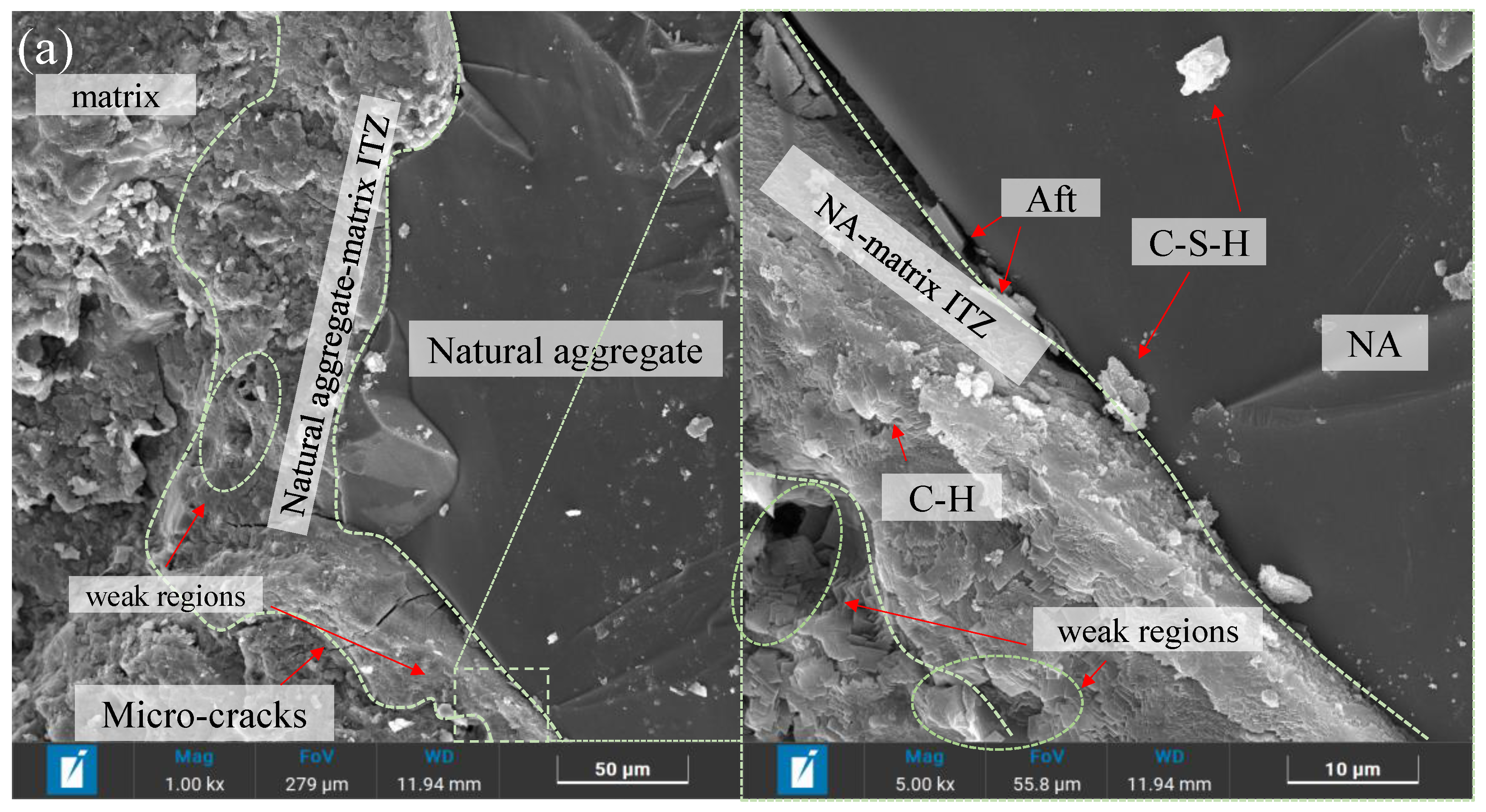
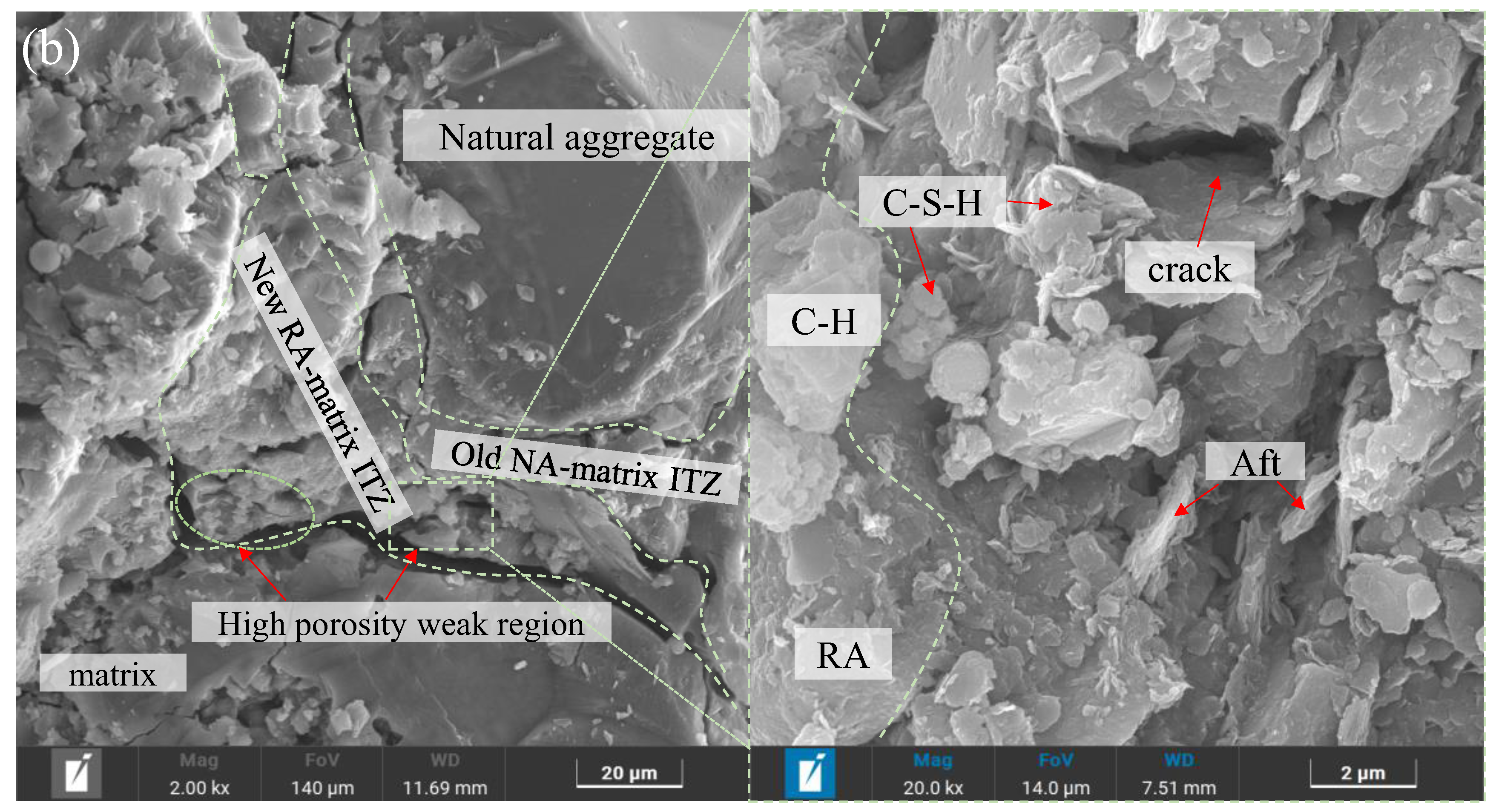
SF’s hydrophilicity induces localized Ca2⁺ depletion, whereas PF’s hydrophobicity inhibits surface hydration, resulting in a heterogeneous distribution of hydration products and the subsequent formation of micro cracks and porous structures. Although alkali activation partially at the old mortar layers fills the pores in RA, insufficient hydration in the ITZ persists due to the higher water absorption of RA, leading to weaker interfaces compared to those of NA.

Author Contributions

Data curation, C.Z.; Investigation, C.Z.; Writing—original draft, L.M.; Formal analysis, L.M.; Funding acquisition, L.M.; Writing—review & editing, B.L.; Visualization, B.L.; Supervision, Q.Z.; Validation, Q.Z. All authors have read and agreed to the published version of the manuscript.

Funding

We appreciate the financial support of the Chinese National Natural Science Foundation (Grant No. 52308248), the Science and Technology Key Project of Henan Province (Grant No. 242102321023; No. 252102320050), and the Research and Practice Project on Teaching Reform in Higher Education of Henan Province (Grant No. 2024SJGLX0855).

Data Availability Statement

The data presented in this study are available on request from the corresponding author due to privacy reasons.

Conflicts of Interest

The authors declare no conflicts of interest.

References

  1. Thomas, B.S.; Yang, J.; Bahurudeen, A.; Chinnu, S.N.; Abdalla, J.A.; Hawileh, R.A.; Hamada, H.M. Geopolymer concrete incorporating recycled aggregates: A comprehensive review. Clean. Mater. 2022, 3, 100056. [Google Scholar] [CrossRef]
  2. Nanyakkara, O.; Gunasekara, C.; Sandanayake, M.; Law, D.W.; Nguyen, K.; Xia, J.; Setunge, S. Alkali activated slag concrete incorporating recycled aggregate concrete: Long term performance and sustainability aspect. Constr. Build. Mater. 2021, 271, 121512. [Google Scholar] [CrossRef]
  3. Shi, X.S.; Collins, F.G.; Zhao, X.L.; Wang, Q.Y. Mechanical properties and microstructures analysis of fly ash geopolymeric recycled concrete. J. Hazard. Mater. 2012, 237–238, 20–29. [Google Scholar] [CrossRef]
  4. Li, B.; Jiang, G.; Hu, J.; Li, Y.; Wu, F.; Qin, Z.; Wang, S. Specimen size effect on compressive and splitting tensile strengths of sustainable geopolymeric recycled aggregate concrete: Experimental and theoretical analysis. J. Clean. Prod. 2024, 434, 140154. [Google Scholar] [CrossRef]
  5. Zheng, Y.; Du, J.; Zheng, L.; Wang, C. Compressive behavior of geopolymer recycled brick aggregate concrete confined by steel tubes. J. Build. Eng. 2023, 70, 106350. [Google Scholar] [CrossRef]
  6. Kan, L.; Wang, F.; Zhang, Z.; Kabala, W.; Zhao, Y. Mechanical properties of high ductile alkali-activated fiber reinforced composites with different curing ages. Constr. Build. Mater. 2021, 306, 124833. [Google Scholar] [CrossRef]
  7. Wang, C.; Zhang, Y.; Ma, Z.; Wang, D. Hysteresis deteriorating behaviors of fiber-reinforced recycled aggregate concrete composites subjected to cyclic compressive loadings. J. Build. Eng. 2022, 49, 104087. [Google Scholar] [CrossRef]
  8. Nis, A.; Eren, N.Q.; Cevik, A. Effects of nanosilica and steel fibers on the impact resistance of slag based self-compacting alkali-activated concrete. Ceram. Int. 2021, 47, 23905–23918. [Google Scholar] [CrossRef]
  9. Amran, M.; Fediuk, R.; Abdelgader, H.S.; Murali, G.; Ozbakkaloglu, T.; Lee, Y.H.; Lee, Y.Y. Fiber-reinforced alkali-activated concrete: A review. J. Build. Eng. 2022, 45, 103638. [Google Scholar] [CrossRef]
  10. Nazir, K.; Canpolat, O.; Uysal, M. Durability properties of steel, polyamide, and polyethylene fiber-reinforced geopolymer mortar made with recycled concrete aggregate and glass powder as fillers. J. Build. Eng. 2023, 76, 107313. [Google Scholar] [CrossRef]
  11. Shaikh, F.U.A. Mechanical and durability properties of fly ash geopolymer concrete containing recycled coarse aggregates. Int. J. Sustain. Built. Environ. 2016, 5, 277–287. [Google Scholar] [CrossRef]
  12. Moulya, H.V.; Chandrashekha, A. Experimental investigation of effect of recycled coarse aggregate properties on the mechanical and durability characteristics of geopolymer concrete. Mater. Today Proc. 2022, 59, 1700–1707. [Google Scholar] [CrossRef]
  13. Kathirvel, P.; Kaliyaperumal, S.R.M. Influence of recycled concrete aggregates on the engineering and durability properties of alkali activated slag concrete. Constr. Build. Mater. 2017, 133, 65–72. [Google Scholar]
  14. Xie, J.; Wang, J.; Rao, R.; Wang, C.; Fang, C. Effects of combined usage of GGBS and fly ash on workability and mechanical properties of alkali activated geopolymer concrete with recycled aggregate. Compos. Part B 2019, 164, 179–190. [Google Scholar] [CrossRef]
  15. Nuaklong, P.; Sata, V.; Chindaprasirt, P. Properties of metakaolin-high calcium fly ash geopolymer concrete containing recycled aggregate from crushed concrete specimens. Constr. Build. Mater. 2018, 161, 365–373. [Google Scholar] [CrossRef]
  16. Pawluczuk, E.; Wichrowska, K.K.; Jimenez, J.R.; Rodríguez, J.M.F.; Morales, D.S. Geopolymer concrete with treated recycled aggregates: Macro and microstructural behavior. J. Build. Eng. 2021, 44, 103317. [Google Scholar] [CrossRef]
  17. Fang, G.; Chen, J.; Dong, B.; Liu, B. Microstructure and micromechanical properties of interfacial transition zone in green recycled aggregate concrete. J. Build. Eng. 2023, 66, 105860. [Google Scholar] [CrossRef]
  18. Pradhan, P.; Panda, S.; Parhi, S.K.; Panigrahi, S.K. Variation in fresh and mechanical properties of GGBS based self-compacting geopolymer concrete in the presence of NCA and RCA. Mater. Today Proc. 2022, 62, 6348–6358. [Google Scholar] [CrossRef]
  19. Kathirvel, P.; Kaliyaperumal, S.R.M. Influence of recycled concrete aggregates on the flexural properties of reinforced alkali activated slag concrete. Constr. Build. Mater. 2016, 102, 51–58. [Google Scholar] [CrossRef]
  20. Xie, J.; Wang, J.; Zhang, B.; Fang, C.; Li, L. Physicochemical properties of alkali activated GGBS and fly ash geopolymeric recycled concrete. Constr. Build. Mater. 2019, 204, 384–398. [Google Scholar] [CrossRef]
  21. Sedaghatdoost, A.; Behfarnia, K.; Bayati, M.; Vaezi, M. Influence of recycled concrete aggregates on alkali-activated slag mortar exposed to elevated temperatures. J. Build. Eng. 2019, 26, 100871. [Google Scholar] [CrossRef]
  22. Li, B.; Wu, F.; Xia, D.; Li, Y.; Cui, K.; Wu, F.; Yu, J. Compressive and flexural behavior of alkali-activated slag-based concrete: Effect of recycled aggregate content. J. Build. Eng. 2023, 67, 105993. [Google Scholar] [CrossRef]
  23. Bernal, S.; Gutierrez, R.; Delvasto, S.; Rodriguez, E. Performance of an alkali-activated slag concrete reinforced with steel fibers. Constr. Build. Mater. 2010, 24, 208–214. [Google Scholar] [CrossRef]
  24. Hammad, N.; EI-Nemr, A.; Hasan, H.E.D. The performance of fiber GGBS based alkali-activated concrete. J. Build. Eng. 2021, 42, 102464. [Google Scholar] [CrossRef]
  25. Hammad, N.; EI-Nemr, A.; Hasan, H.E.D. Flexural performance of reinforced Alkali-activated concrete beams incorporating steel and structural Macro synthetic polypropylene fiber. Constr. Build. Mater. 2022, 324, 126634. [Google Scholar] [CrossRef]
  26. El-Hassan, H.; Elkholy, S. Enhancing the performance of Alkali-activated slag-fly ash blended concrete through hybrid steel fiber reinforcement. Constr. Build. Mater. 2021, 311, 125313. [Google Scholar] [CrossRef]
  27. Zhou, M.; He, X.; Wang, H.; Wu, C.; He, J.; Wei, B. Mechanical properties and microstructure of ITZs in steel and polypropylene hybrid fiber-reinforced concrete. Constr. Build. Mater. 2024, 415, 135119. [Google Scholar] [CrossRef]
  28. Zhao, Q.; Wang, Y.; Xie, M.; Huang, B. Experimental study on mechanical behavior of steel fiber reinforced geopolymeric recycled aggregate concrete. Constr. Build. Mater. 2022, 356, 129267. [Google Scholar] [CrossRef]
  29. Li, B.; Yu, S.; Gao, B.; Li, Y.; Wu, F.; Xia, D.; Chi, Y.; Wang, S. Effect of recycled aggregate and steel fiber contents on the mechanical properties and sustainability aspects of alkali-activated slag-based concrete. J. Build. Eng. 2023, 66, 105939. [Google Scholar] [CrossRef]
  30. Tang, Z.; Hu, Y.; Tam, V.W.Y.; Li, W. Uniaxial compressive behaviors of fly ash/slag-based geopolymeric concrete with recycled aggregates. Cem. Concr. Comp. 2019, 104, 103375. [Google Scholar] [CrossRef]
  31. Zhao, Q.; Dong, S.; Xie, M. Experiments on stress-strain curve of steel fiber reinforced geopolymer recycled concrete under uniaxial compression. J. Build. Struct. 2022, 43, 255–265. (In Chinese) [Google Scholar]
  32. Li, B.; Wang, C.; Yu, S.; Yu, J.; Wang, S. Compressive constitutive behavior of steel fiber reinforced geopolymeric recycled aggregate concrete: Experimental investigation and analytical model. Structures 2023, 58, 105531. [Google Scholar] [CrossRef]
  33. Fang, G.; Ho, W.K.; Tu, W.; Zhang, M. Workability and mechanical properties of alkali-activated fly ash-slag concrete cured at ambient temperature. Construct. Build. Mater. 2018, 172, 476–487. [Google Scholar] [CrossRef]
  34. Li, B.; Xu, L.; Shi, Y.; Chi, Y.; Liu, Q.; Li, C. Effects of fiber type, volume fraction and aspect ratio on the flexural and acoustic emission behaviors of steel fiber reinforced concrete. Constr. Build. Mater. 2018, 181, 474–486. [Google Scholar] [CrossRef]
  35. Chachar, K.H.; Oad, M.; Memon, B.A.; Siyal, Z.A.; Siyal, K.F. Workability and Flexural Strength of Recycled Aggregate Concrete with Steel Fibers. Eng. Technol. Appl. Sci. 2023, 13, 11051–11057. [Google Scholar] [CrossRef]
  36. GB/T 50081-2019; Standard for Test Methods of Concrete Physical and Mechanical Properties. Ministry of Housing and Urban-Rural Development of the People’s Republic of China: Beijing, China, 2019. (In Chinese)
  37. Li, B.; Chi, Y.; Xu, L.; Shi, Y.; Li, C. Experimental investigation on the flexural behavior of steel-polypropylene hybrid fiber reinforced concrete. Constr. Build. Mater. 2018, 191, 80–94. [Google Scholar] [CrossRef]
  38. Xu, L.; Deng, F.; Chi, Y. Nano-mechanical behavior of the interfacial transition zone between steel-polypropylene fiber and cement paste. Constr. Build. Mater. 2017, 145, 619–638. [Google Scholar] [CrossRef]
  39. Yurt, U. An experimental study on fracture energy of alkali activated slag composites incorporated different fibers. J. Build. Eng. 2020, 32, 101519. [Google Scholar] [CrossRef]
  40. ASTM/C1609M-2012; Standard Test Method for Flexural Performance of Fiber-Reinforced Concrete. ASTM: West Conshohocken, PA, USA, 2012.
  41. Banthia, N.; Majdzadeh, F.; Wu, J.; Bindiganavile, V. Fiber synergy in hybrid fiber reinforced concrete (HyFRC) in flexure and direct shear. Cem. Concr. Compos. 2014, 48, 91–97. [Google Scholar] [CrossRef]
  42. Huang, L.; Chi, Y.; Xu, L.; Chen, P.; Zhang, A. Local bond performance of rebar embedded in steel-polypropylene hybrid fiber reinforced concrete under monotonic and cyclic loading. Constr. Build. Mater. 2016, 103, 77–92. [Google Scholar] [CrossRef]
  43. Hasnaoui, A.; Ghorbel, E.; Wardeh, G. Performance of metakaolin/slag-based geopolymer concrete made with recycled fine and coarse aggregates. J. Build. Eng. 2021, 42, 102813. [Google Scholar] [CrossRef]
Figure 1. Morphologies of CA and fibers. (a) NA, (b) RA, (c) PF, and (d) SF.
Buildings 15 01723 g001
Figure 2. Test methods. (a) Cubic compressive strength, (b) splitting tensile strength, and (c) flexural behavior [https://doi.org/10.1016/j.conbuildmat.2023.131417] (accessed on 14 May 2025).
Buildings 15 01723 g002
Figure 3. Compressive strength of HFRGRAC with (a) SF volume fraction, (b) SF aspect ratio, (c) PF volume fraction and (d) RA content.
Buildings 15 01723 g003
Figure 4. Splitting tensile strength of HFRGRAC on (a) SF volume fraction, (b) SF aspect ratio, (c) PF volume fraction and (d) RA content.
Buildings 15 01723 g004aBuildings 15 01723 g004b
Figure 5. Failure pattern of HFRGRAC specimens.
Buildings 15 01723 g005
Figure 6. The fracture surfaces of HFRGRAC specimens.
Buildings 15 01723 g006
Figure 7. Load–deflection curves of HFRGRAC on (a) SF volume fraction, (b) SF aspect ratio, (c) PF volume fraction and (d) RA content.
Buildings 15 01723 g007
Figure 8. Flexural strength of HFRGRAC on (a) SF volume fraction, (b) SF aspect ratio, (c) PF volume fraction and (d) RA content.
Buildings 15 01723 g008
Figure 9. Flexural deflection of HFRGRAC on (a) SF volume fraction, (b) SF aspect ratio, (c) PF volume fraction and (d) RA content.
Buildings 15 01723 g009
Figure 10. Flexural toughness of HFRGRAC on (a) SF volume fraction, (b) SF aspect ratio, (c) PF volume fraction and (d) RA content.
Buildings 15 01723 g010aBuildings 15 01723 g010b
Figure 11. Microstructure of (a) SF matrix and (b) PF matrix ITZs. (c) EDAX analysis.
Buildings 15 01723 g011
Figure 12. Fracture propagation diagram. (a) Original specimen, (b) emergence and (c) propagation of microcracks, (d) emergence and (e) propagation of cracks.
Buildings 15 01723 g012
Figure 13. Microstructure of (a) NA matrix and (b) RA matrix ITZs.
Buildings 15 01723 g013aBuildings 15 01723 g013b
Table 1. The chemical constitutions of GGBS and FA.
BindersComposition (%)Density (g/cm3)Specific Surface Area (m2/kg4)
CaOSiO2Al2O3MgOSO3K2ONa2OMnOFe2O3TiO2
Slag36.8226.7519.6611.12.650.290.840.370.320.942.8455
FA5.645.124.21.212.11.410.850.260.850.142.2330
Table 2. Physical and mechanical characteristics of NA and RA [https://doi.org/10.1016/j.jobe.2023.105939] (accessed on 14 May 2025).
CA TypeSize (mm)Bulk Density (kg/m3)Crushing Value (%)Impact Value (%)Specific Gravity (kg/m3)Fineness ModulusWater Absorption (%)
NA5–2014319.71328732.71.68
RA5–20136615.32826552.65.85
Table 3. Mechanical properties and apparent morphologies of fibers.
Fiber TypeCharacteristicLength, l (mm)Diameter, d (mm)Aspect Ratio, l/dElastic Modulus (GPa)Density (kg/m3)Tensile Strength (MPa)
SFHooked-end20/30/400.540/60/8019078501200
PFMonofilament90.032727540.230.91396
Table 4. Mix proportions and basic mechanical strength indexes of HFRGRAC.
SpecimenMaterials (kg·m−3)fc/MPaft/MPa
SFPFGGBSFARiver SandNARASodium SilicateNaOHWaterWater Reducer
SB00P10-50-0.03211.562.8925.118.8118.8137.633.0770.5933.88555.105.60
SB05P10-501.360.03211.562.8925.118.8118.8137.633.0770.5933.88564.7810.01
SB10P10-502.720.03211.562.8925.118.8118.8137.633.0770.5933.88568.3810.80
SB15P10-504.080.03211.562.8925.118.8118.8137.633.0770.5933.88570.8812.41
SA10P10-502.720.03211.562.8925.118.8118.8137.633.0770.5933.88565.8011.41
SC10P10-502.720.03211.562.8925.118.8118.8137.633.0770.5933.88565.0811.90
SB10P00-502.72-11.562.8925.118.8118.8137.633.0770.5933.88561.748.60
SB10P05-502.720.01611.562.8925.118.8118.8137.633.0770.5933.88566.3310.71
SB10P15-502.720.04711.562.8925.118.8118.8137.633.0770.5933.88567.8711.52
SB10P10-002.720.03211.562.8925.137.63-37.633.0770.5933.88574.4811.02
SB10P10-252.720.03211.562.8925.128.229.4137.633.0770.5933.88568.9710.90
SB10P10-752.720.03211.562.8925.19.4128.2237.633.0770.5933.88567.6310.40
SB10P10-1002.720.03211.562.8925.1-37.6337.633.0770.5933.88558.689.63
SB00P00-50--11.562.8925.118.8118.8137.633.0770.5933.88553.976.97
SB05P00-501.36-11.562.8925.118.8118.8137.633.0770.5933.88559.287.50
SB15P00-504.08-11.562.8925.118.8118.8137.633.0770.5933.88565.229.93
SB00P05-50-0.01611.562.8925.118.8118.8137.633.0770.5933.88551.955.30
SB00P15-50-0.04711.562.8925.118.8118.8137.633.0770.5933.88558.805.71
SB05P15-501.360.04711.562.8925.118.8118.8137.633.0770.5933.88562.159.63
SB15P05-504.080.01611.562.8925.118.8118.8137.633.0770.5933.88572.3211.87
Note: SA, SB, and SC denote SF with aspect ratios of 40, 60, and 80, respectively. SB00, SB05, SB10, and SB15 indicate SF volume fractions of 0%, 0.5%, 1.0%, and 1.5%, respectively. P00, P05, P10, and P15 represent PF volume fractions of 0%, 0.05%, 0.1%, and 0.15%, respectively; −00, −25, −50, −75, and −100 correspond to RA replacement rates of 0%, 25%, 50%, 75%, and 100%, respectively. For example, SB05P15-50 designates a mixture with 0.5% SF (with an aspect ratio of 60), 0.15% PF, and 50% RA replacement rate.
Table 5. The flexural characteristics of HFRGRAC.
SpecimenPeak PointResidual Load (kN)Flexural Toughness (Joule)
δpeak
(mm)
Ppeak
(kN)
fpeak
(MPa)
PL300PL150PL100Ω300ΩL150ΩL100
SB00P10-500.58518.0315.407------
SB05P10-500.65121.7906.5385.3112.9641.76210.58614.65117.122
SB10P10-500.87925.9217.77516.7075.7962.86515.26325.99030.339
SB15P10-501.09128.7488.62527.7248.8963.69015.54131.08436.801
SA10P10-500.89923.8927.16721.9727.0761.62815.08627.04331.484
SC10P10-501.07430.0519.01529.03812.6927.58115.74335.72345.797
SB10P00-500.68024.4207.32610.1356.0423.69914.05821.45125.817
SB10P05-500.97224.6027.38123.4366.1983.56714.23824.09028.888
SB10P15-500.93826.7188.01417.3087.0343.12115.76325.04629.649
SB10P10-001.02731.3099.39131.0176.1262.36916.92827.58733.047
SB10P10-250.90127.0828.12416.3237.7474.57616.76926.97232.854
SB10P10-750.87424.4417.33117.8073.4162.52614.86821.38324.403
SB10P10-1000.81022.3426.70210.2831.6620.70413.45317.62918.722
Table 6. The α of mechanical strengths of HFRGRAC.
SF Content (%)PF Content (%)
Compressive StrengthSplitting Tensile StrengthFlexural Strength
0.050.10.150.050.10.150.050.10.15
0111111111
0.5-1.0700.962-1.1951.132-0.9751.015
1.01.1161.0851.0091.1781.1671.1780.8480.8530.851
1.51.1521.064-1.1281.110-0.8240.799-
Disclaimer/Publisher’s Note: The statements, opinions and data contained in all publications are solely those of the individual author(s) and contributor(s) and not of MDPI and/or the editor(s). MDPI and/or the editor(s) disclaim responsibility for any injury to people or property resulting from any ideas, methods, instructions or products referred to in the content.

