
Research Status and Prospects of Grouted Sleeve Connections in Prefabricated Structures


Abstract
1. Introduction
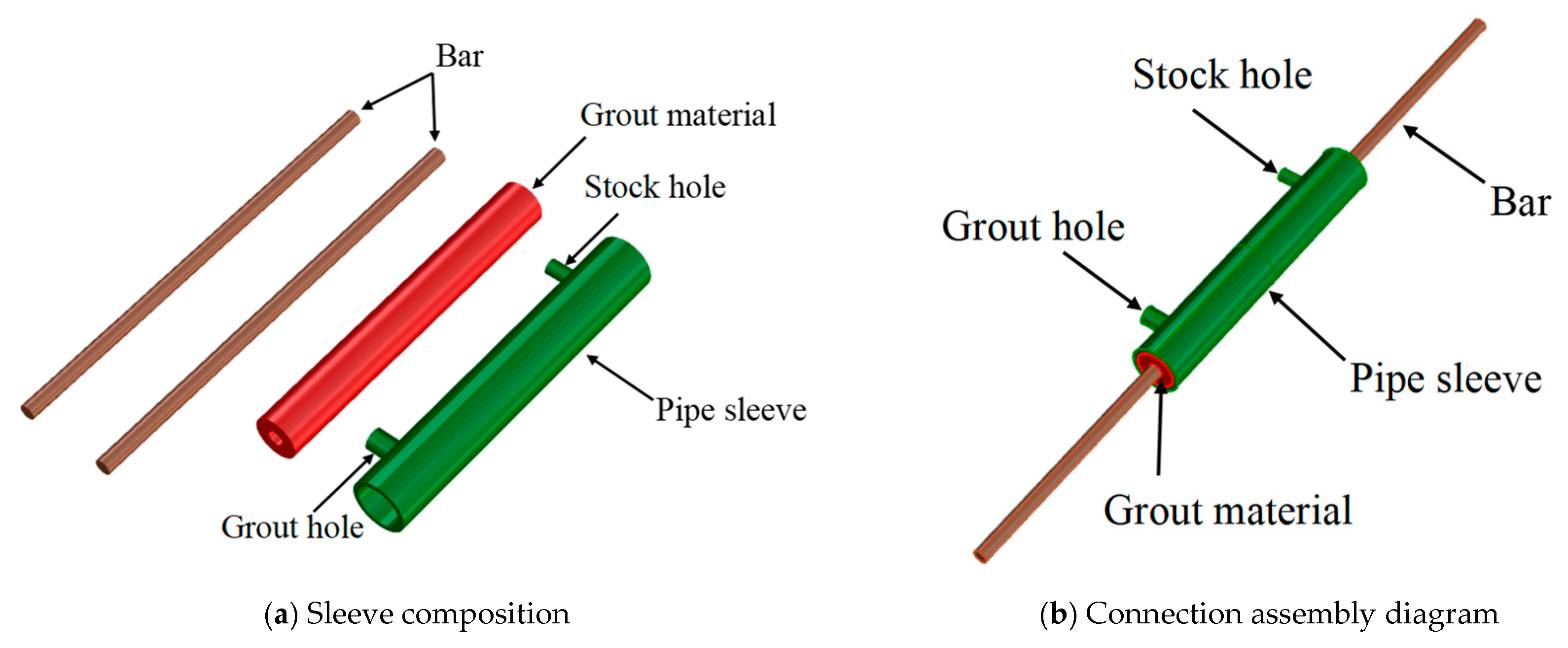
2. Use and Characteristics of Sleeves
2.1. Standard Regulation
2.2. Structural Form
2.3. Technical Requirements
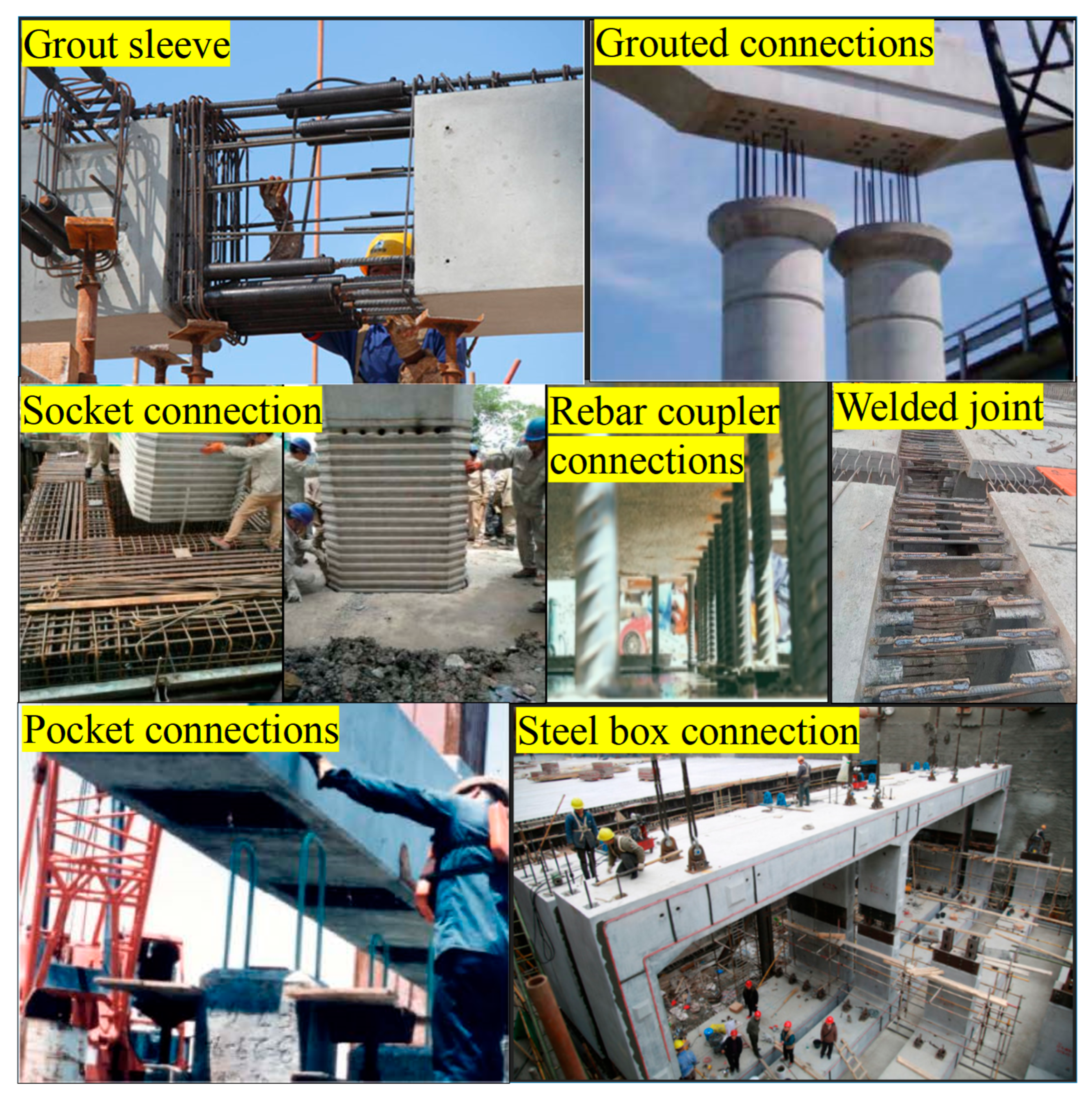
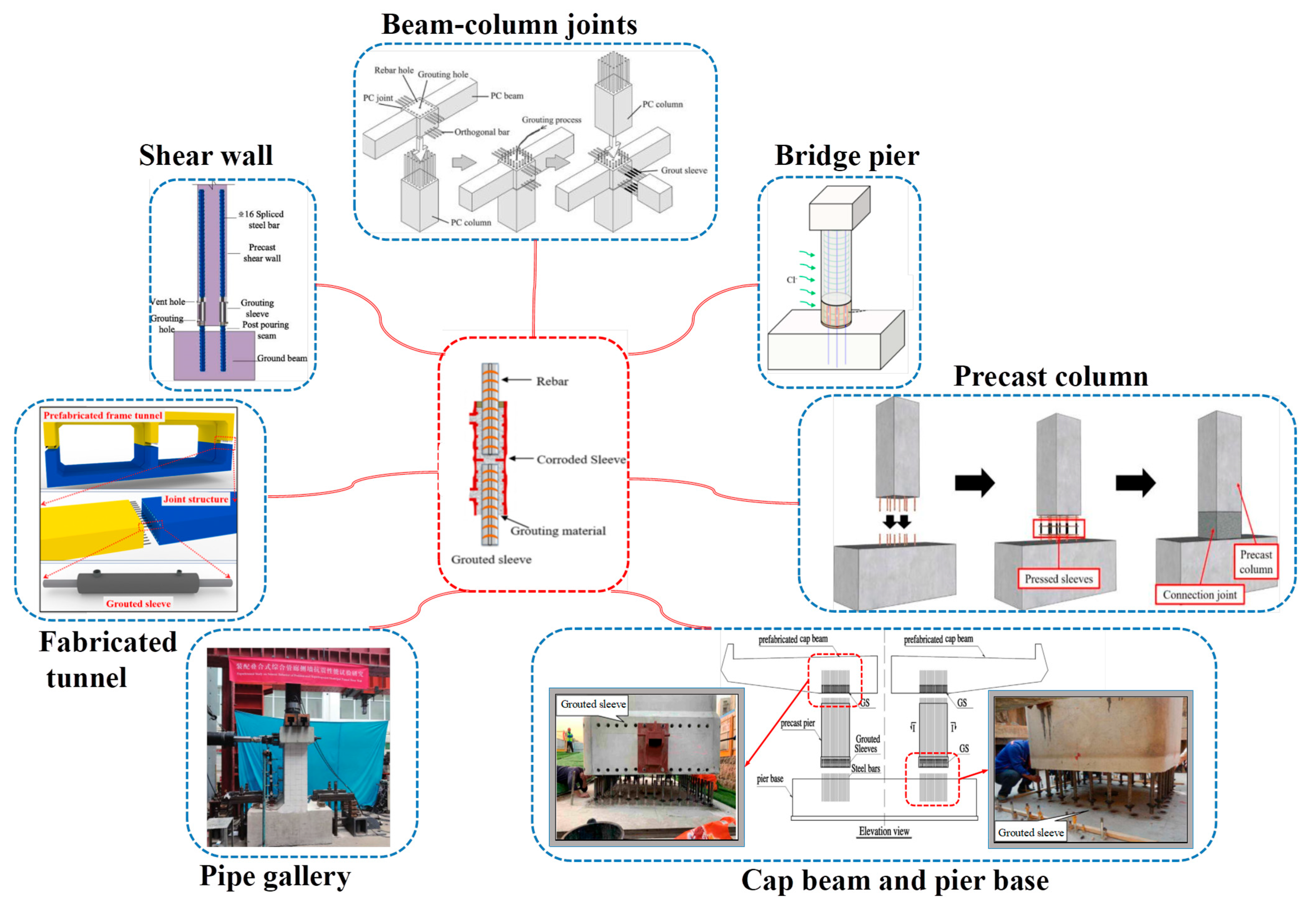
2.4. Application Scenario
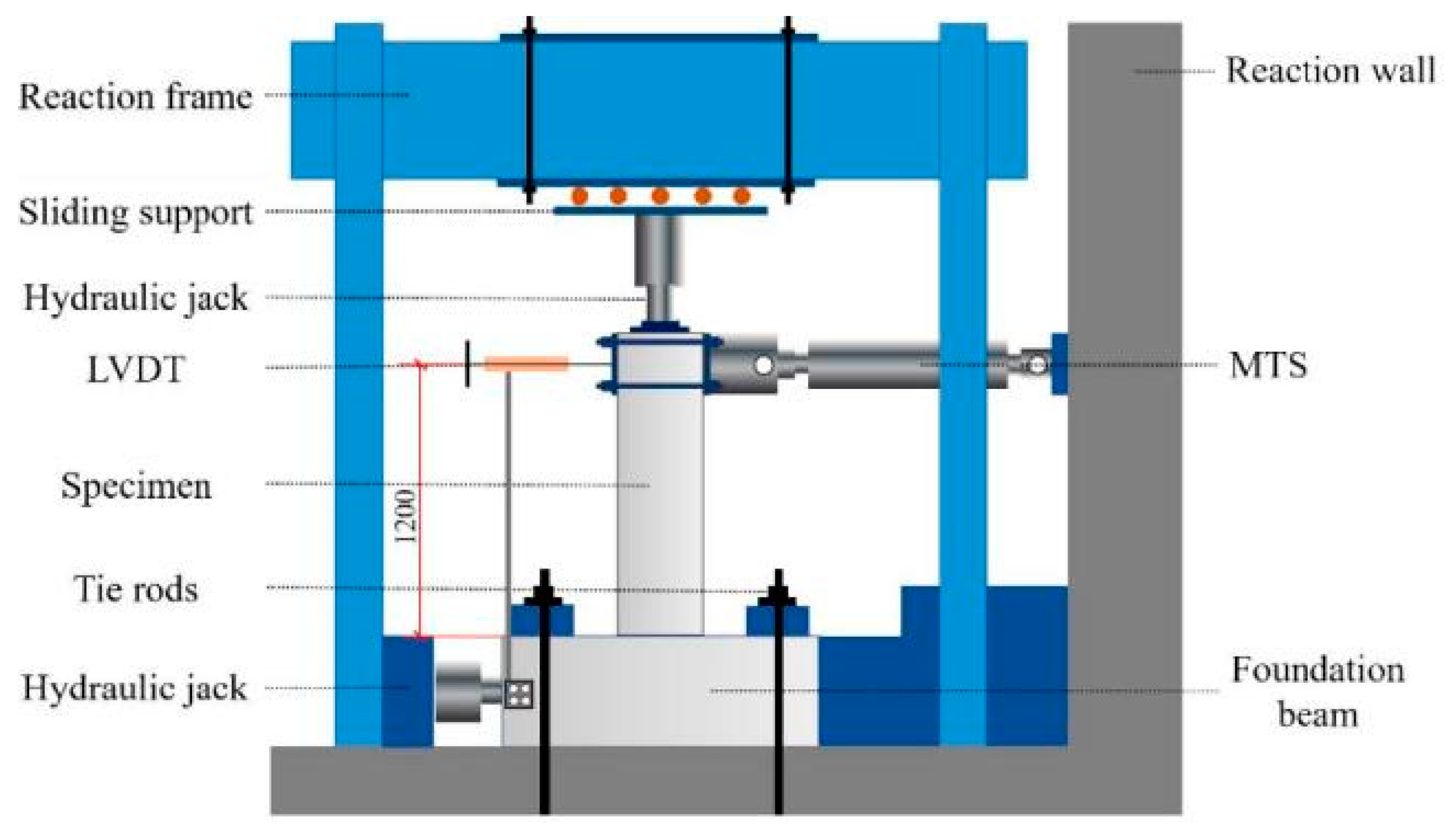
3. Performance Test
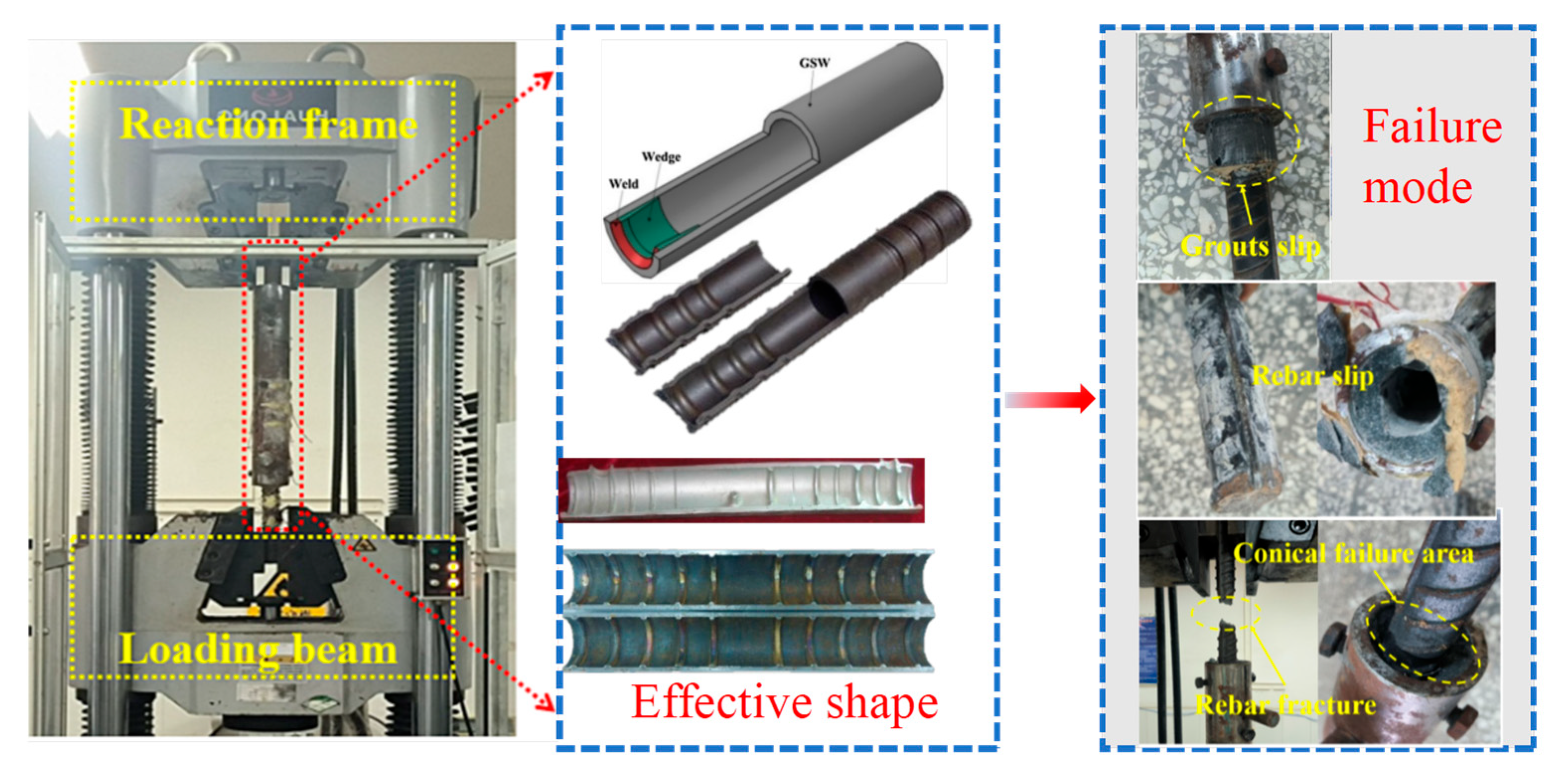
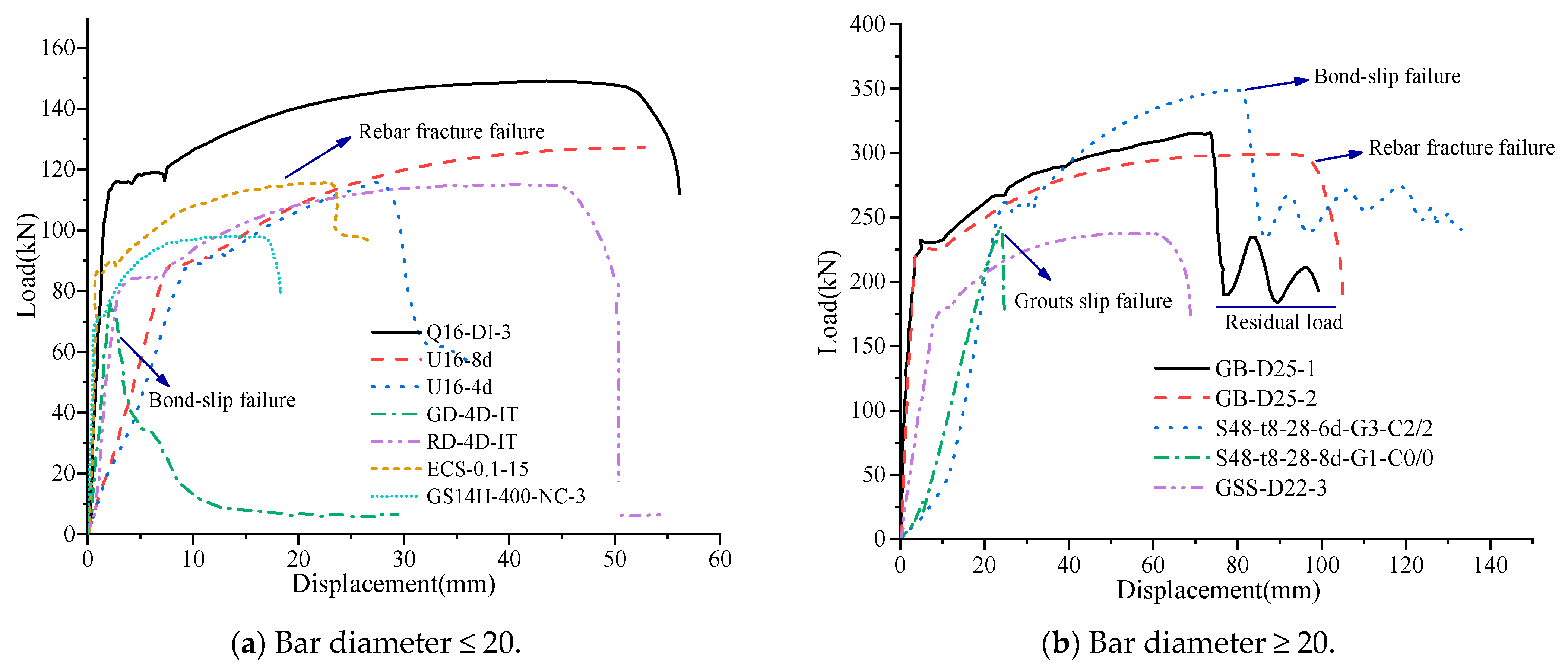
3.1. Tensile Properties
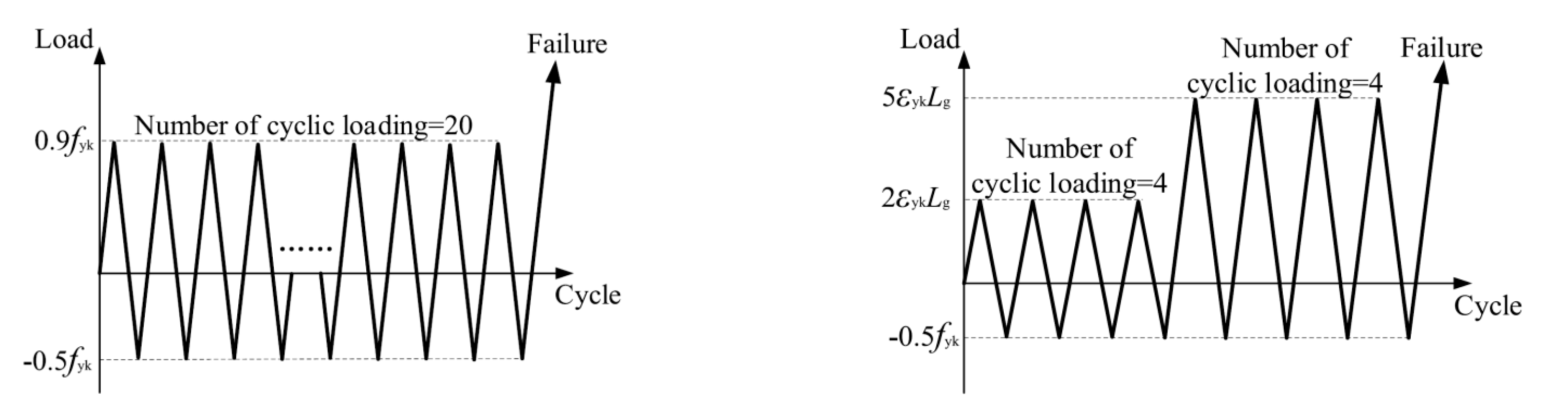
3.2. Fatigue Performance
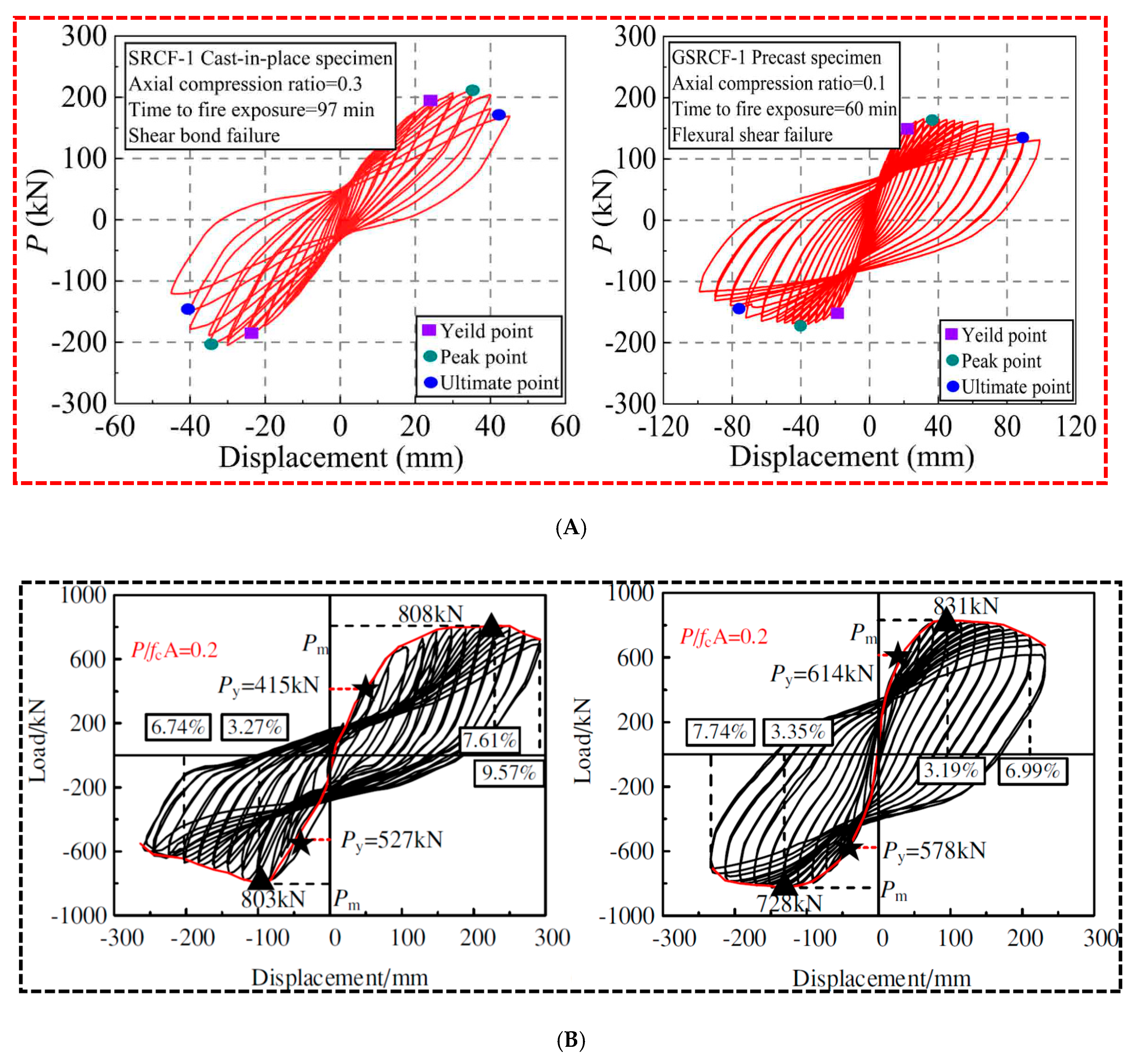
3.3. Seismic Performance
4. Factors Influencing Sleeve Connection Performance
4.1. Bar
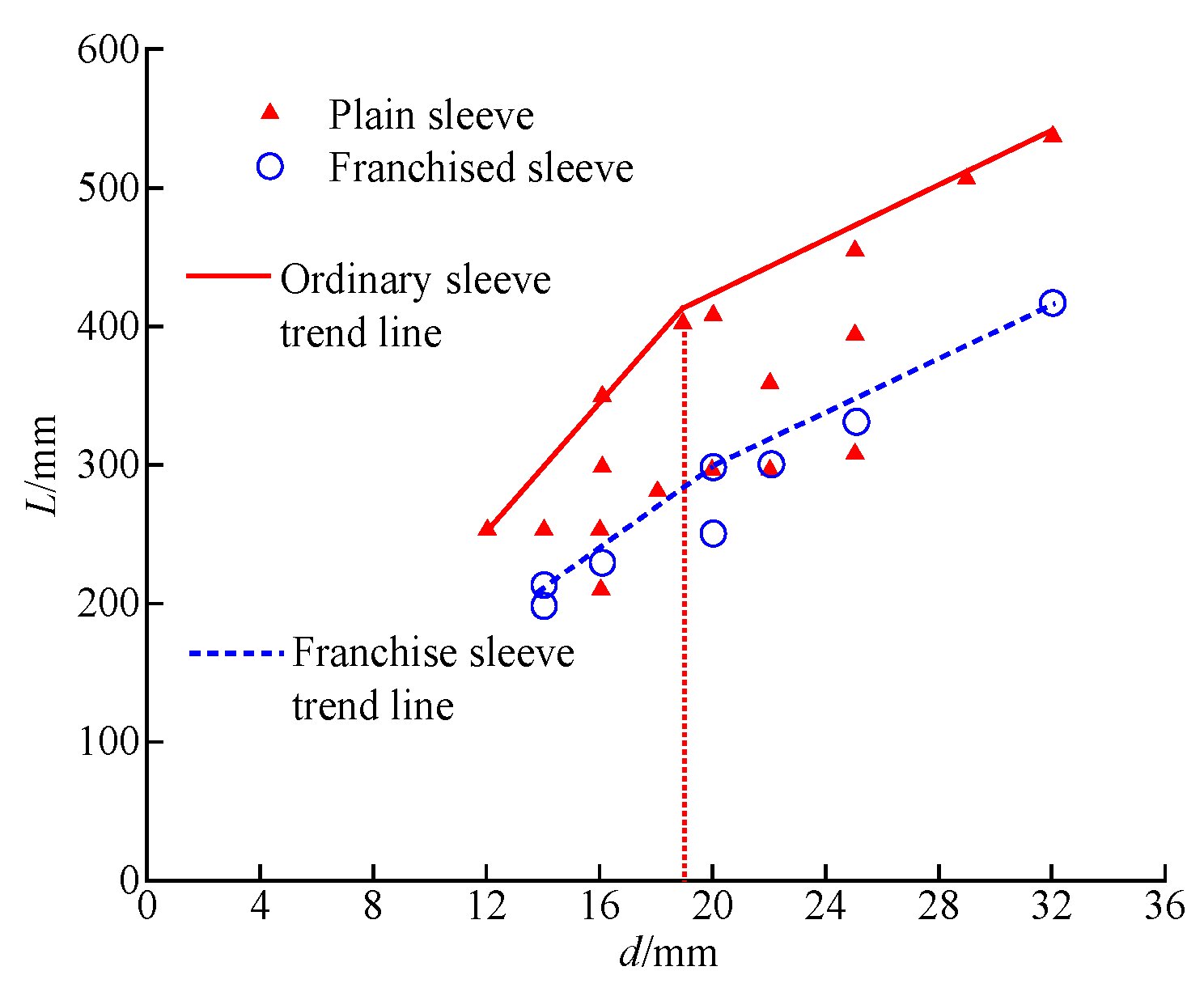
4.1.1. Anchorage Length of Steel Bar
4.1.2. Diameter
4.1.3. Intensity
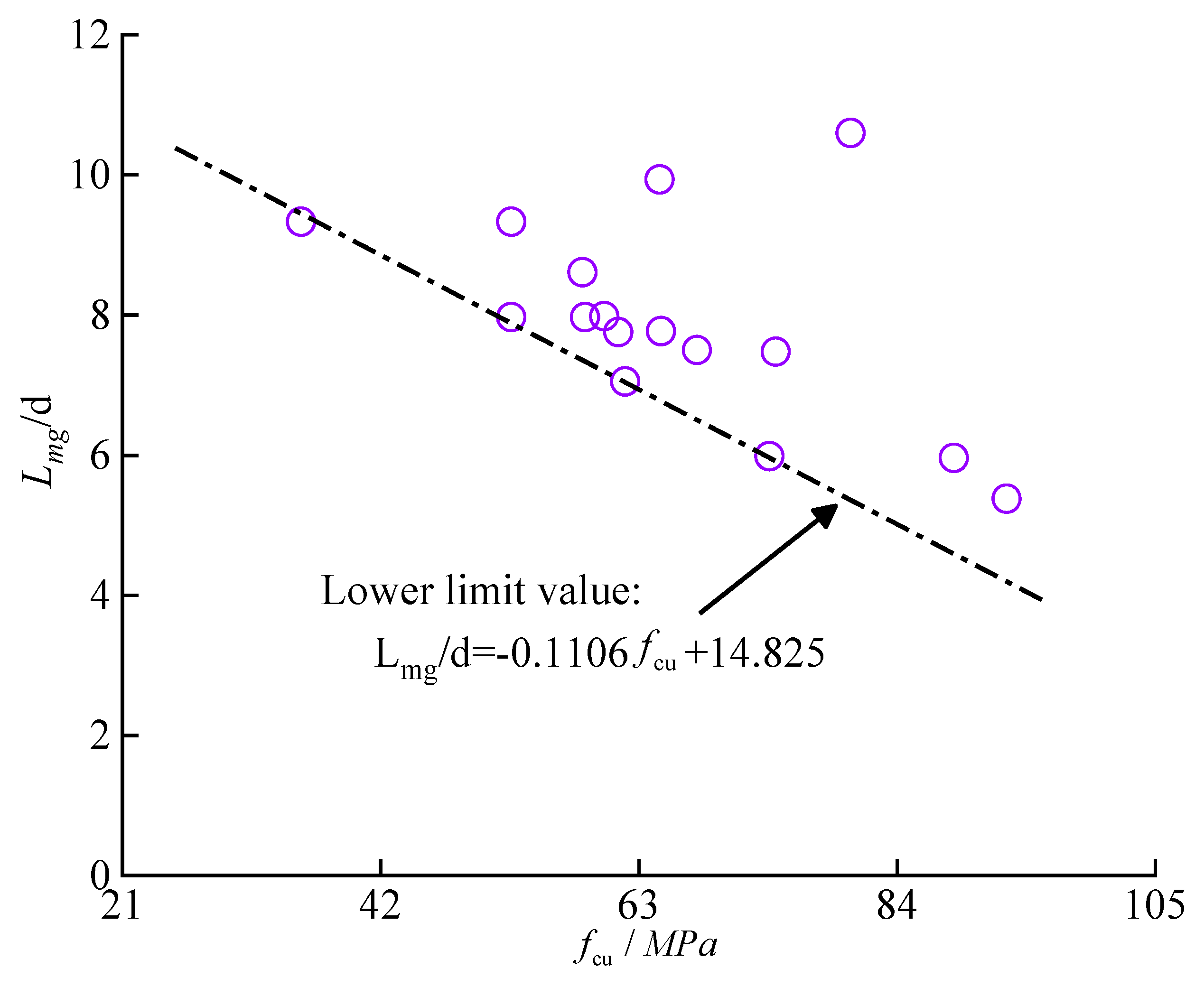
4.2. Grout Material
4.2.1. Grouting Material Type

| Sort | Reference | Type | 28 d Compressive Strength (MPa) | 30 min Fluidity | Bar Diameter (mm) | Anchorage Length (mm) | Ultimate Tensile Strength of Rebar fu (MPa) | Ultimate Tensile Load of Sleeve (kN) | Ultimate Tensile Strength of Sleeve fk (MPa) | Failure Mode | fk/fu Ratio |
|---|---|---|---|---|---|---|---|---|---|---|---|
| Special grout | Huang et al. [14] | Ordinary nonshrinkage material | 60.8 | 290 | 28 | 8 d | 596 | 369.6 | 600.24 | Slip of steel bar | 1.01 |
| Shao et al. [76] | Special grout material | 103.2 | 280 | 32 | 7 d | 612.06 | 499.8 | 621.45 | 1.02 | ||
| Lu et al. [37] | Ordinary grout material | 79.2 | / | 20 | 8 d | 591 | 182 | 579.32 | Fracture of steel bar | 0.98 | |
| Zheng et al. [40] | 70.2 | 290 | 25 | 7 d | 625 | 300.8 | 612.79 | 0.98 | |||
| Kim [51] | Mortar grout material | 98 | / | 25 | 7.5 d | 689 | 322.72 | 658.00 | 0.96 | ||
| Lin and Wu [52] | Ordinary grout material | 84 | 270 | 32 | 6 d | 586 | 463 | 575.69 | Slip of steel bar | 0.98 | |
| Improved grout | Zhang et al. [83] | Polypropylene fibre | 87 | 365 | 18 | 8 d | 649 | 164.7 | 647.23 | Fracture of steel bar | 1.00 |
| Polyvinyl alcohol fibre | 86.1 | 380 | 18 | 8 d | 649 | 164.8 | 647.60 | 1.00 | |||
| Basalt fibre | 90 | 380 | 18 | 8 d | 649 | 165.1 | 648.8 | 1.00 | |||
| Wu et al. [84] | High strength concrete | 80.79 | / | 20 | 7.15 d | 632.5 | 472.81 | 637.65 | 1.01 | ||
| Lei et al. [71] | Custom fibre grout | 143 | 290 | 18 | 8 d | 652.3 | 168.84 | 663.50 | 1.02 | ||
| UHPC grout | Wang et al. [13] | Unfibre | 105.2 | 289 | 28 | 5 d | 624 | 391.6 | 636.00 | 1.02 | |
| Reinforced fibre | 126.0 | 258 | 28 | 5 d | 624 | 325.7 | 528.90 | 0.85 | |||
| Huang et al. [14] | Unfibre | 89.9 | 289 | 28 | 8 d | 596 | 373.4 | 606.41 | 1.02 | ||
| Add basalt fibre | 97.3 | 253 | 28 | 8 d | 596 | 374.1 | 607.55 | 1.02 | |||
| Shao et al. [76] | Reinforced fibre | 120.8 | 268 | 28 | 7 d | 602.19 | 377 | 612.26 | 1.02 | ||
| 120.8 | 268 | 32 | 8 d | 612.06 | 501 | 622.94 | 1.02 | ||||
| Fu et al. [85] | Unfibre | 119.6 | 280 | 32 | 8 d | 836.7 | 674.14 | 838.65 | 1.00 | ||
| Reinforced fibre | 128.4 | 262 | 32 | 8 d | 836.7 | 674.75 | 838.41 | 1.00 | |||
| Lei et al. [71] | Commercial UHPC | 97.2 | 310 | 16 | 8 d | 654.7 | 128.48 | 639.01 | 0.98 |
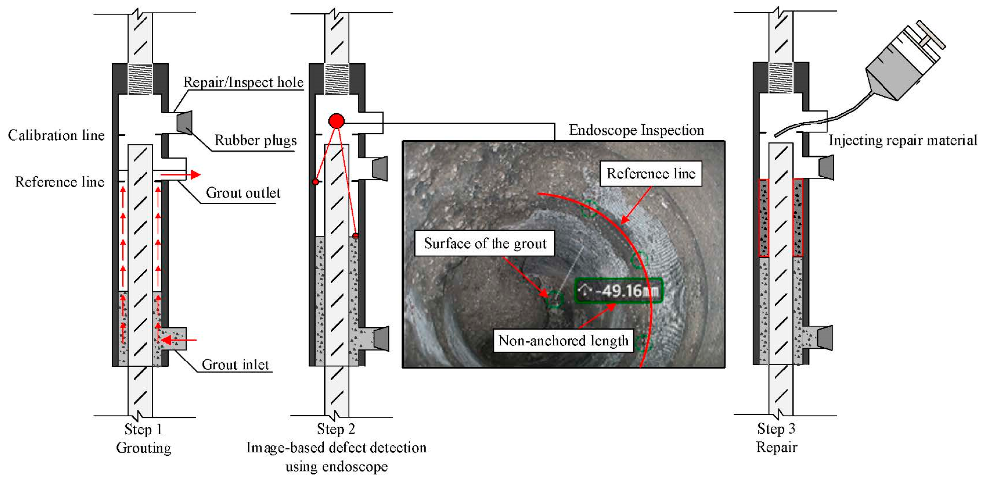
4.2.2. Grouting Material Defects
4.3. Sleeve Pipe Sleeve
4.4. Temperature
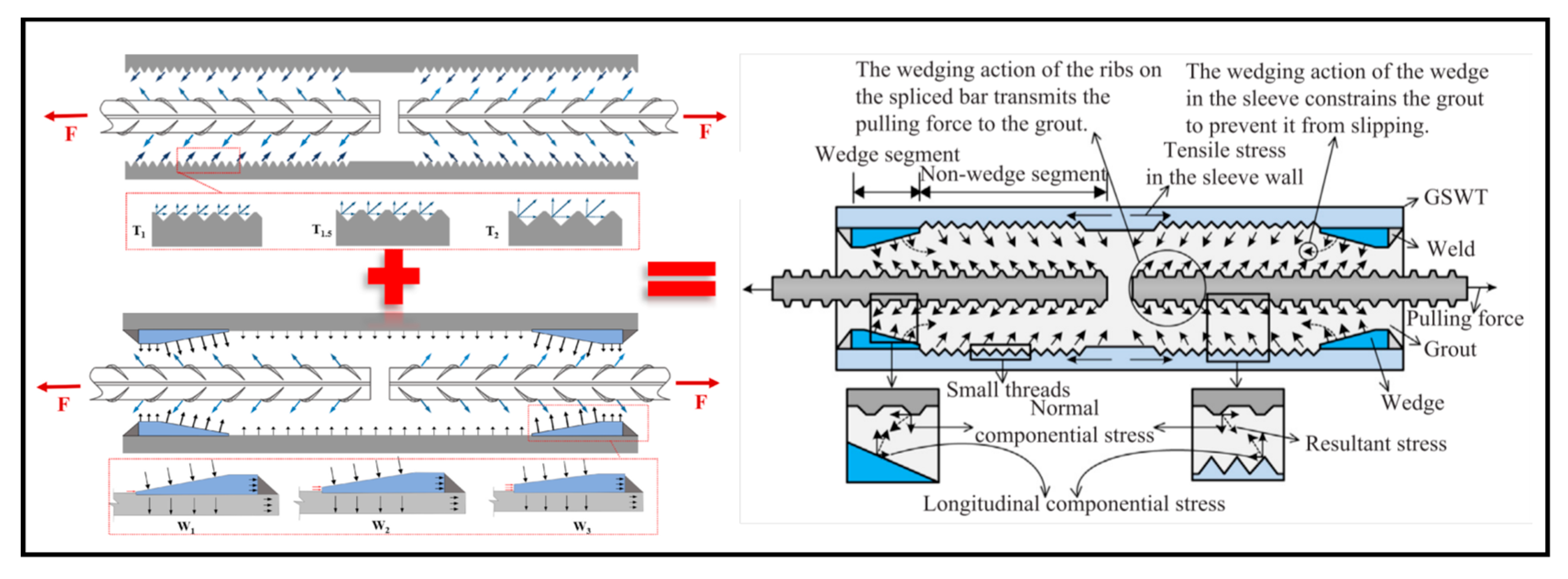
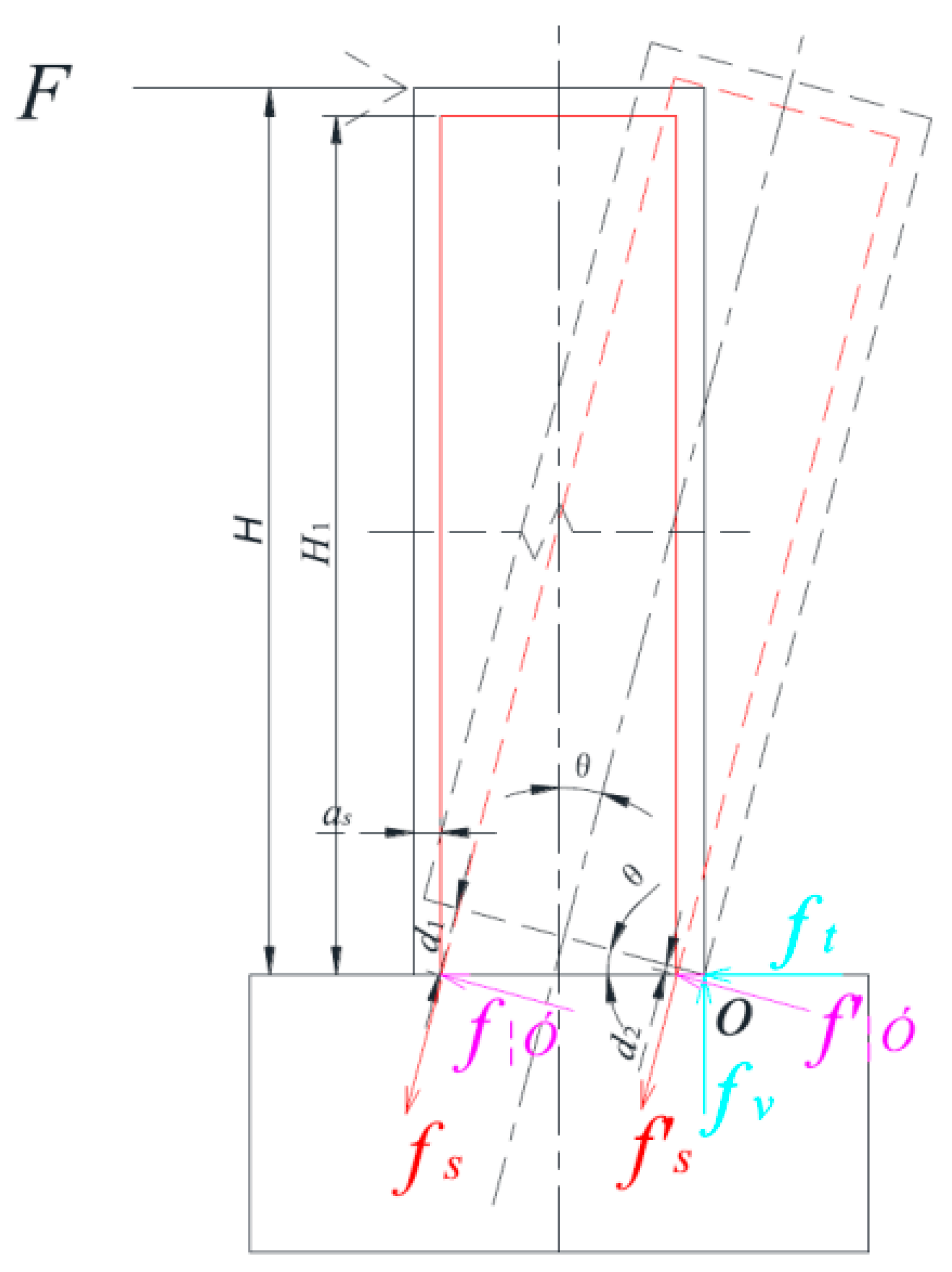
5. Force Transfer Mechanism


6. Performance Evaluation
7. Conclusions
- (1)
- Japanese standards are more detailed in the classification of sleeve performance indicators, whereas Chinese standards are more specific in the definition of performance test parameters. Noncircular sleeves perform better than circular sleeves do in conventional applications. Currently, grouting techniques for sleeves are relatively single-purpose across different structural forms, and the integration of different techniques needs to be considered. With continuous improvements in the material and processing properties of grout, reinforcing bars, and sleeves, the application scope of sleeves has expanded to various building structural forms.
- (2)
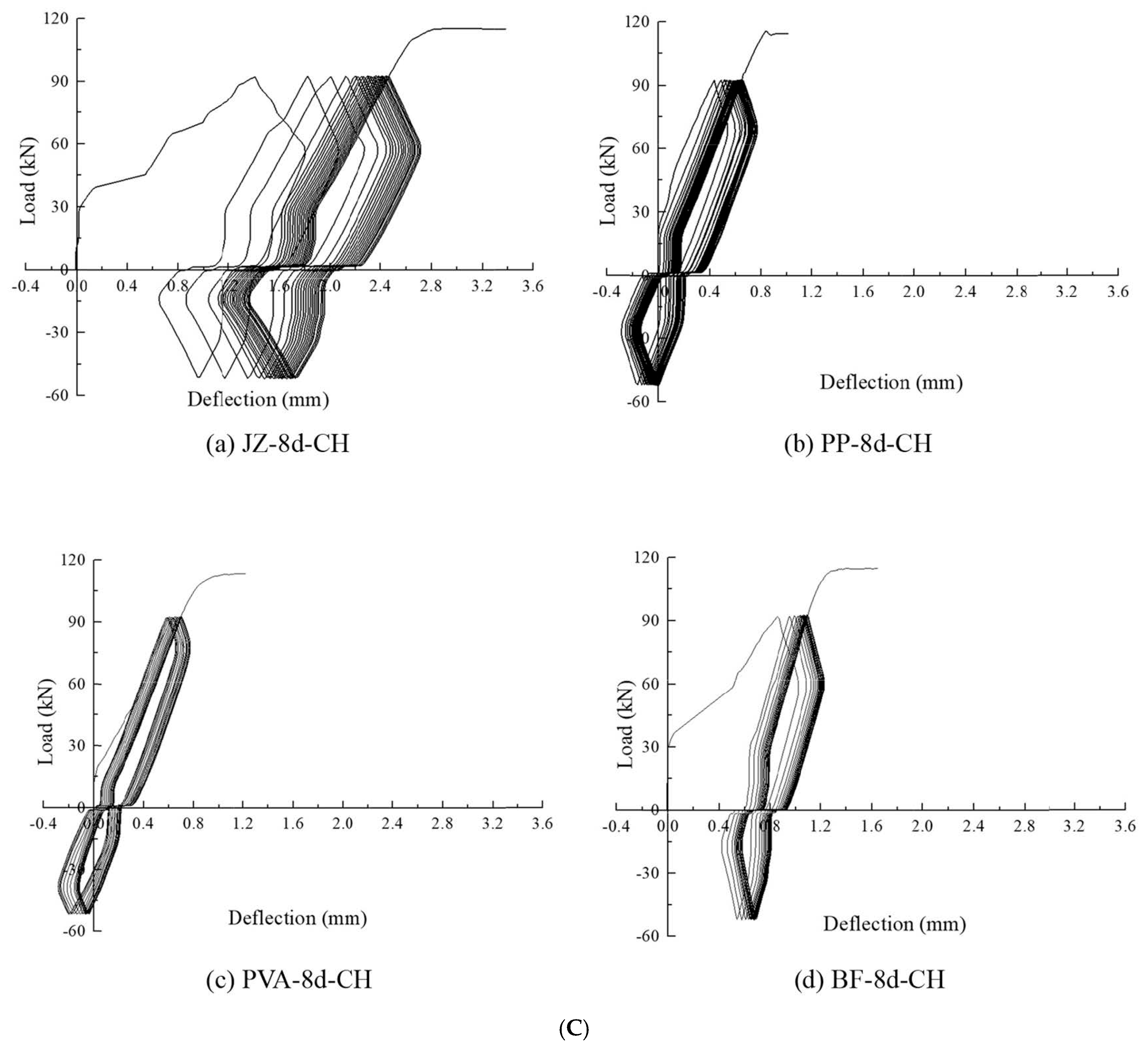
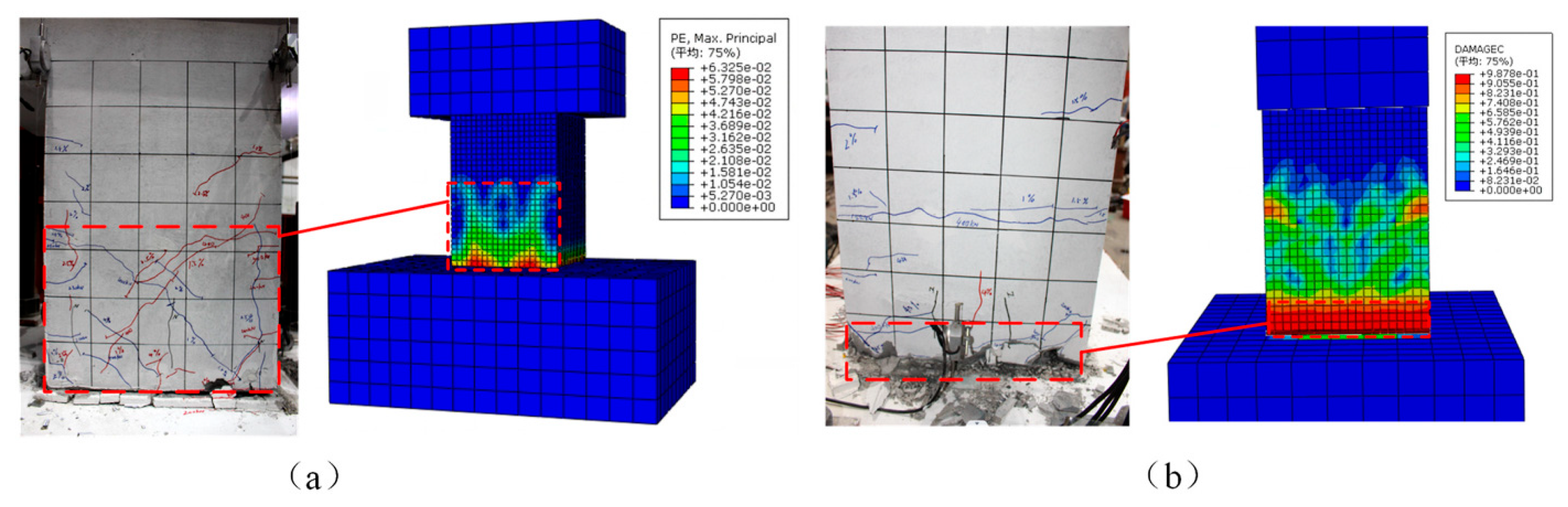
- Modifying the end of the sleeve (e.g., welding steel plates, wedge blocks, or reducing the diameter) significantly enhances the tensile performance of the sleeve. Altering the smooth inner surface of the sleeve to add shear keys (e.g., threads, welded ring ribs, annular grooves) further improves tensile performance. Fatigue performance tests have shown that factors such as grout defects, increased fibre content, and elevated loading temperatures negatively affect sleeve performance. Damage to the grout at the sleeve end can reach approximately 8% of the total sleeve length, and the initial stiffness can decrease by an average of approximately 38.5%. In seismic tests, reinforcing bar slip and yielding often occur, preventing the grouted sleeve from fully exploiting its structural performance.
- (3)
- The anchorage length of reinforcing bars should not be less than the critical anchorage length, and the anchorage segment includes both elastic and inelastic sections. Theoretical calculations of the anchorage length can serve as a basis for structural design. The diameter of reinforcing bars is most influenced by the inner diameter of the sleeve; larger diameters are not always better, as they result in greater displacement. Increasing the strength of reinforcing bars can increase the load-bearing capacity by approximately 5.4% to 23.7%, but the anchorage length must be correspondingly increased to meet the tensile requirements.
- (4)
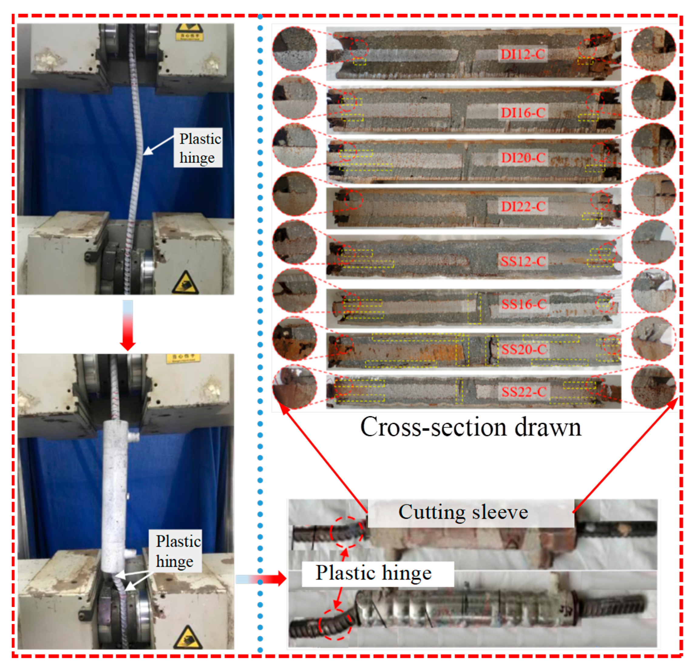
- Grout can be classified into three types: specialized grout, modified grout, and UHPC grout. The tensile strength of the sleeve is positively correlated with the compressive strength of the grout, but fibres can reduce the flowability of the grout and increase the likelihood of defects. The most common defects in sleeves are grout leakage and reinforcing bar eccentricity. Grout leakage can significantly affect the load-bearing capacity and durability of the sleeve. When the reinforcing bar is offset from the centre line of the sleeve by less than 6 mm, the impact is relatively limited. Defect filling and monitoring technologies are now quite mature, allowing for the combination of different techniques to address various defects.
- (5)
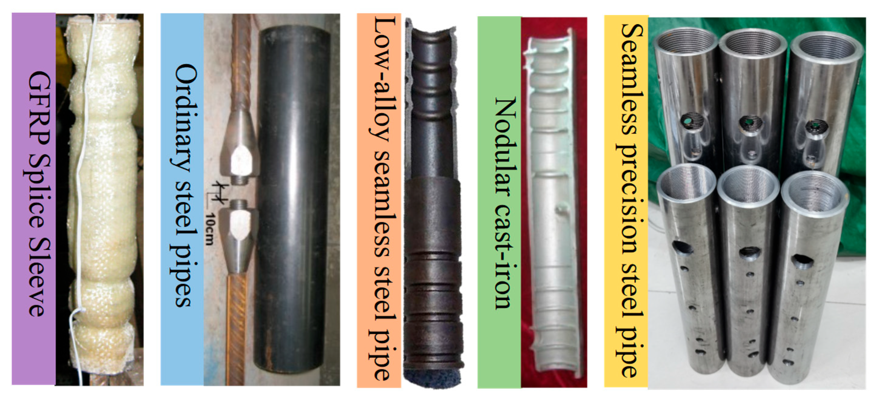
- Sleeve casings can be made of cast iron, alloy steel, or GFRP. Processing the casing can weaken the mechanical properties of the material, so the depth of the threads should not exceed one-eighth of the casing wall thickness. The ratio of the outer diameter to the wall thickness (OD/WT) significantly affects sleeve performance. The wall thickness of the sleeve should be greater than 1/13 of the diameter of the anchored reinforcing bar but should not be excessively thick. The impact of temperature on the tensile performance of the sleeves is most significant at 400 °C.
- (6)
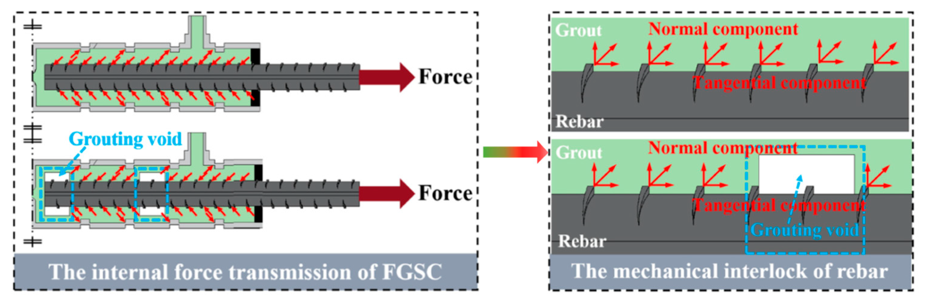
- The load-transfer mechanism involves the interaction among reinforcing bars, grout, and sleeve. The ribs on the reinforcing bars provide pressure and frictional resistance to the grout, along with chemical bonding forces. The casing enhances tensile performance by increasing surface friction and providing shear keys, combined with the passive constraint effect of the casing. Performance evaluation theories have confirmed that adjusting key factors in conventional sleeves can significantly influence performance.
8. Prospects
- (1)
- Grouted sleeve connection technology is well understood within the traditional framework of strength and stiffness assessment; however, its contributions to enhancing structural resilience have not been systematically investigated. Therefore, conducting theoretical analyses to quantify how changes in sleeve parameters affect overall structural resilience and proposing specific metrics for resilience contribution hold promising prospects for future research.
- (2)
- The long-term performance and reliability of sleeve connections are highly important. Currently, accurate and high-precision life prediction models are needed to ensure and prevent safety issues arising from structural damage or ageing. Further research is needed in this area.
- (3)
- The constitutive model for the slip between reinforcing bars and grout in grouted sleeves needs further clarification. The coupled effects of high temperatures, different loading conditions, and the presence of defects require more attention. Research on and the development of admixtures for grout, degradation models for sleeve performance after corrosion, and the selection of high-strength aluminium alloys and other materials for casings need to be explored further.
Author Contributions
Funding
Data Availability Statement
Conflicts of Interest
References
- Huang, Z.; Zhang, C.L.; Ma, S.K.; Zhang, J.B.; Zhu, Q.X. Study of the mechanical behaviour and damage characteristics of three new types of joints for fabricated rectangular tunnels using a numerical approach. Tunn. Undergr. Space Technol. 2021, 118, 104184. [Google Scholar] [CrossRef]
- Huang, Z.; Bai, H.W.; Ma, S.K.; Liang, B.; Quan, J.Y. Large-scale Testing of Bending Behavior of Circular and Square Steel Tenon Joints of Fabricated Tunnel. China J. Highw. Transp. 2022, 35, 233–244. [Google Scholar]
- Parastesh, H.; Hajirasouliha, I.; Ramezani, R. A new ductile moment-resisting connection for precast concrete frames in seismic regions: An experimental investigation. Eng. Struct. 2014, 70, 144–157. [Google Scholar] [CrossRef]
- Liu, Y.; Li, X.P.; Zheng, X.H.; Song, Z. Experimental study on seismic response of precast bridge piers with double-grouted sleeve connections. Eng. Struct. 2020, 221, 111023. [Google Scholar] [CrossRef]
- Guan, D.Z.; Jiang, C.; Guo, Z.X.; Ge, H.B. Development and seismic behavior of precast concrete beam-to-column connections. J. Earthq. Eng. 2018, 22, 234–256. [Google Scholar] [CrossRef]
- Zheng, Y.F.; Guo, Z.X.; Guan, D.Z.; Zhang, X. Parametric study on a novel grouted rolling pipe splice for precast concrete construction. Constr. Build. Mater. 2018, 166, 452–463. [Google Scholar] [CrossRef]
- Tests on Rebar Splices in Reinforced Concrete Columns Using NMB Splice Sleeves; NPD-024; Nisso Master Builders Co., Ltd. Available online: https://discovery.patsnap.com/company/nisso-master-builders/ (accessed on 2 May 2025).
- Yu, Z.M. Sleeve grouting steel joint in Japan. Archit. Technol. 1991, 50–53. [Google Scholar]
- Yang, X.R.; Huang, M.Q.; Lin, F. Research strategies on new prefabricated technology for underground metro station. Urban Rail Transit 2019, 5, 145. [Google Scholar] [CrossRef]
- Wang, J.Q.; Wang, Z.; Gao, Y.F.; Zhu, J.Z. Review on seismic behavior of precast piers: New material, new concept, and new application. Eng. Mech. 2019, 36, 1–23. [Google Scholar]
- Marsh, M.L.; Stanton, J.F.; Wernli, M.; Eberhard, M.O.; Garrett, B.E.; Weinert, M.D. Application of Accelerated Bridge Construction Connections in Moderate-to-High Seismic Regions; Report No. NCHRP Report 698; Transportation Research Board; The National Academies Press: Washington, DC, USA, 2011. [Google Scholar]
- Brenes, F.J. Anchorage of Grouted Vertical Duct Connections for Precast Bent Caps. Ph.D. Thesis, The University of Texas at Austin, Austin, TX, USA, 2005. [Google Scholar]
- Wang, Z.; Zhu, J.; Wang, J.; Zhao, G.T.; Sun, S.L.; Zhang, J. Experimental study on a novel UHPC grout-filled pipe sleeve with mechanical interlocking for large-diameter deformed bars. Eng. Struct. 2021, 226, 111358. [Google Scholar] [CrossRef]
- Huang, Z.; Yang, Y.; Zhang, J.B.; Ma, S.K.; Cao, C. Experimental study on the tensile performance of a large-diameter UHPC grouted sleeve with thread. Eng. Struct. 2023, 294, 116707. [Google Scholar] [CrossRef]
- Yee, A.A. Splice Sleeve for Reinforcing Bars with Cylindrical Shell: US19850764063. U.S. Patent 4, 627, 212 A, 31 January 2013. [Google Scholar]
- Yee, A.A.; Hon, D. Structural and economic benefits of precast/prestressed concrete construction. PCI J. 2001, 46, 34–43. [Google Scholar] [CrossRef]
- ACI Committee 439. Mechanical connections of reinforcement bars. Concr. Int. 1983, 5, 24–35. [Google Scholar]
- Hisada, M.; Tamai, S.; Furuichi, K. Overview of “Recommendation for Design, Fabrication and Evaluation of Anchorages and Joints in Reinforcing Bars [2020]”. Concr. J. 2020, 58, 189–195. [Google Scholar] [CrossRef]
- JGJ 1-2014; Technical Specification for Precast Concrete Structures. China Architecture & Building Press: Beijing, China, 2014.
- JGT 398-2019; Grouting Sleeve for Rebar Splicing. China Architecture & Building Press: Beijing, China, 2012.
- JGT 408-2019; Cementitious Grout for Sleeve of Rebar Splicing. China Architecture & Building Press: Beijing, China, 2013.
- JGJ 335-2015; Technical Specification for Grout Sleeve Splicing of Rebars (Edition 2023). China Architecture & Building Press: Beijing, China, 2023.
- JGJ 107-2019; Technical Specification for Mechanical Splicing of Steel Reinforcing Bars. China Architecture & Building Press: Beijing, China, 2019.
- Jansson, P.O. Evaluation of Grout-Filled Mechanical Splices for Precast Concrete Construction. 2008. Available online: https://www.researchgate.net/publication/239588765 (accessed on 2 May 2025).
- Ameli, M.J.; Parks, J.E.; Brown, D.N.; Pantelides, C.P. Seismic evaluation of grouted splice sleeve connections for precast reinforced concrete bridge piers. In Proceedings of the 7th National Seismic Conference on Bridges & Highways, Oakland, CA, USA, 20–22 May 2013. [Google Scholar]
- Wang, D.H.; Liu, X.D.; Liu, Y.L.; Guo, H.L. Experimental study on ultimate tensile bearing capacity of cement grouting sleeve connection. Build. Struct. 2015, 6, 21–23. [Google Scholar]
- Wang, A.J. Rebars splicing technology and application of grout & parallel thread. Constr. Mech. 2010, 31, 21–25. [Google Scholar]
- Einea, A.A.; Yamane, T.; Tadros, M.K. Grout-filled pipe splices for precast concrete construction. PCI J. 1995, 40, 82–93. [Google Scholar] [CrossRef]
- Ling, J.H.; Rahman, A.B.A.; Mirasa, A.K.; Hamid, Z.A. Performance of CS-sleeve under direct tensile load: Part I: Failure modes. Malays. J. Civ. Eng. 2008, 20, 89–106. [Google Scholar] [CrossRef]
- Rahman, A.B.A.; Ling, J.H.; Hamid, Z.A.; Hamid, Z.A. Development of splice connections for precast concrete structures. Adv. Mater. Res. 2014, 980, 132–136. [Google Scholar] [CrossRef]
- Rahman, A.B.A.; Yoon, L.H.; Ibrahim, I.S.; Mohamed, R.N.; Mohammad, S.; Saim, A.A. Performance of grouted splice sleeves with tapered bars under axial tension. Appl. Mech. Mater. 2015, 789, 1176–1180. [Google Scholar] [CrossRef]
- Zheng, Y.F. Research on Rebar Splicing System by GDPS Grout Filled Coupling Sleeve. Ph.D. Thesis, Southeast University, Nanjing, China, 2016. [Google Scholar]
- Wu, X.B.; Lin, F.; Wang, T. Experimental research on effects of grout age and types of steel bars on mechanical behavior of grout sleeve splicing for reinforcing bars. Build. Struct. 2013, 43, 77–82. [Google Scholar]
- Gao, Q. Study on Connection Performance of Grouted Sleeve Based on Surfacing Formed Rib. Ph.D. Thesis, Shenyang Jianzhu University, Liaoning, China, 2022. [Google Scholar]
- Henin, E.; Morcous, G. Non-proprietary bar splice sleeve for precast concrete construction. Eng. Struct. 2015, 83, 154–162. [Google Scholar] [CrossRef]
- Kim, H.K. Structural performance of steel pipe splice for SD500 high-strength reinforcing bar under cyclic loading. Archit. Res. 2008, 10, 13–23. [Google Scholar]
- Lu, Z.W.; Huang, J.; Li, Y.B.; Dai, S.D.; Peng, Z.; Liu, X.; Zhang, M.Z. Mechanical behaviour of grouted sleeve splice under uniaxial tensile loading. Eng. Struct. 2019, 186, 421–435. [Google Scholar] [CrossRef]
- Dai, S.B.; Zheng, X.L.; Huang, J.; Li, Y.B.; Liu, X. Experiment on behavior of composite square grout-filled pipe splice. J. Archit. Civ. Eng. 2020, 37, 43–61. [Google Scholar]
- Sayadi, A.A.; Rahman, A.B.A.; Sayadi, A.; Bahmani, M.; Shahryari, L. Effective of elastic and inelastic zone on behavior of glass fiber reinforced polymer splice sleeve. Constr. Build. Mater. 2015, 80, 38–47. [Google Scholar] [CrossRef]
- Zheng, Y.F.; Guo, Z.X.; Lu, J.B.; Chen, X.G.; Xiao, Q.D. Performance and confining mechanism of grouted deformed pipe splice under tensile load. Adv. Struct. Eng. 2016, 19, 86–103. [Google Scholar] [CrossRef]
- Ling, J.H.; Rahman, A.B.A.; Ibrahim, I.S.; Hamid, Z.A. Tensile capacity of grouted splice sleeves. Eng. Struct. 2016, 111, 285–296. [Google Scholar] [CrossRef]
- GBT 1348-2019; Spheroidal Graphite Iron Castings. Standards Press of China: Beijing, China, 2019.
- Shi, M.X.; Wei, Z.B.; Zhang, Q.M.; Feng, X.N. Research Summary of Connection Status of Grouting Sleeve for Prefabricated Bridge Pier. Sci. Technol. Ind. 2024, 24, 178–188. [Google Scholar]
- Hu, X.; Liu, S.; Song, Z.; Xue, W.C. Experimental study on mechanical properties of joints in precast assembled utility tunnel connected with grouting sleeve. Constr. Technol. 2018, 47, 122–125. [Google Scholar]
- Zhong, Z.L.; Li, G.F.; Shi, S.H.; Zhao, M.; Du, X.L. Experimental study on out-of-plane seismic performance of sidewall connections of utility tunnels with composite plates. Eng. Mech. 2024, 41, 39–49+105. [Google Scholar]
- Du, X.L.; Liu, H.T.; Xu, C.S.; Jin, L.; Luo, F.R.; Li, S.M. Study on seismic performance of beam-column-slab interior joints in cross section of assembled monolithic subway station. J. Build. Struct. 2019, 40, 51–60. [Google Scholar]
- Yan, Q.; Chen, T.; Xie, Z. Seismic experimental study on a precast concrete beam-column connection with grout sleeves. Eng. Struct. 2018, 155, 330–344. [Google Scholar] [CrossRef]
- Wu, M.; Liu, X.; Liu, H.; Du, X.L. Seismic performance of precast short-leg shear wall using a grouting sleeve connection. Eng. Struct. 2020, 208, 110338. [Google Scholar] [CrossRef]
- Yuan, C.M.; Cai, J.; Chen, Q.J.; Liu, X.P.; Zuo, Z.L.; He, A.; Huang, H.J. Experimental study on seismic behaviour of precast recycled fine aggregate concrete columns with pressed sleeve connections. Structures 2023, 48, 1373–1390. [Google Scholar] [CrossRef]
- Yuan, W.; Wang, Y.; Dong, Z.; Fang, Q.H. Experimental study on mechanical properties of corroded grouted sleeve splice. Constr. Build. Mater. 2024, 412, 134797. [Google Scholar] [CrossRef]
- Kim, H.-K. Confining effect of mortar-filled steel pipe splice. Archit. Res. 2008, 10, 27–35. [Google Scholar]
- Lin, F.; Wu, X.B. Mechanical performance and stress-strain relationships for grouted splices under tensile and cyclic loadings. Int. J. Concr. Struct. Mater. 2016, 10, 435–450. [Google Scholar] [CrossRef]
- Gao, Q.; Zhao, W.J. Experimental study on performance of grouted sleeve connection with surfacing forming under uniaxial tensile load. J. Build. Struct. 2022, 43, 208–219. [Google Scholar]
- Yin, F.F.; Yin, S.P.; Cheng, Z.J.; Chen, N.H.; Wang, Y. Experimental research on dynamic mechanical properties of fully-grouted sleeve connections. Constr. Build. Mater. 2021, 288, 123125. [Google Scholar] [CrossRef]
- Lei, S.; Liu, L.; Wu, F.; Lin, W.W.; Peng, K. Experimental study on tensile mechanism of UHPC grouted sleeve splice. Constr. Build. Mater. 2023, 364, 129922. [Google Scholar] [CrossRef]
- Zheng, G.Y.; Kuang, Z.P.; Xiao, J.Z.; Pan, Z.F. Mechanical performance for defective and repaired grouted sleeve connections under uniaxial and cyclic loadings. Constr. Build. Mater. 2020, 233, 117233. [Google Scholar] [CrossRef]
- Han, R.Q.; Li, S.L.; Sun, W.C. Effect of grouting material strength on bond strength of sleeve and acoustic emission characterization of bond failure damage process. Constr. Build. Mater. 2022, 324, 126503. [Google Scholar] [CrossRef]
- Zhang, W.; He, C.; Zhang, J.; Yi, W.; Deng, X. Mechanical behavior of post-fire half-grouted sleeve connection covered by concrete. Constr. Build. Mater. 2019, 201, 218–231. [Google Scholar] [CrossRef]
- Zheng, Y.F.; Guo, Z.X. Experimental study and finite element analysis on behavior of deformed gout-filled pipe splice. J. Build. Struct. 2016, 37, 94–102. [Google Scholar]
- Liu, C.; Pan, L.F.; Liu, H.; Tong, H.W.; Yang, Y.B.; Chen, W. Experimental and numerical investigation on mechanical properties of grouted-sleeve splices. Constr. Build. Mater. 2020, 260, 120441. [Google Scholar] [CrossRef]
- Zheng, Y.F.; Guo, Z.X. Structural Performance of Innovative Grout Sleeve Splicing for Rebars under Cyelic Loading. J. Hunan Univ. (Nat. Sci.) 2016, 43, 131–140. [Google Scholar]
- Wang, T.; Yu, M.; Lia, X.Y.; Yan, Z.G.; Saaf, M.S.; Ye, J.J. Experimental investigation on the post-fre cyclic behavior of grouted sleeve connections. Constr. Build. Mater. 2021, 279, 122394. [Google Scholar] [CrossRef]
- Zhang, P.; Su, Y.; Fan, J.; Feng, H.; Shao, J.; Guo, H.J.; Gao, D.; Sheikh, S. Experimental research on the mechanical behavior of grouted sleeves with fiber-reinforced grouting material under cyclic loading. Structures 2021, 34, 2189–2204. [Google Scholar] [CrossRef]
- Fan, W.; Su, H.X.; He, Y.B.; Sun, W.B.; Shao, X.D. Experimental investigation on UHPC-based gravity-type half grouted sleeve connections under tensile and cyclic loadings. J. Build. Eng. 2022, 61, 105284. [Google Scholar] [CrossRef]
- Li, X.M.; Gao, R.D.; Zhang, F.W.; Wang, Z.L.; Xiao, S.; Xu, Q.F. Experimental study on influenee of grouting defects on high tensile-compressive stress reversed and high tensile-compressive deformation reversed properties of joints. Build. Struct. 2023, 53, 54–57. [Google Scholar]
- Lu, Z.Y.; Gao, S.; Liu, G.H.; Lin, J.X.; Zhu, J.T.; Xie, J.H. Comparison of ductile iron and seamless steel pipes for use in grouted sleeve splices under monotonic and cyclic loads. J. Build. Eng. 2023, 71, 106496. [Google Scholar] [CrossRef]
- Xu, C.S.; Liu, H.T.; Du, X.L. Experimental study on connection performance of grouted sleeve splicing for rebars under high stress repeated tension-compression loading. J. Build. Struct. 2018, 39, 178–184+193. [Google Scholar]
- Gao, Q.; Zhao, W.J. Experimental study on performance of grouted sleeve connection with surfacing forming under high stress repeated tension-compression load. J. Build. Struct. 2022, 43, 220–227. [Google Scholar]
- Li, Y.B.; Zhang, L.H.; Zhang, Q.G.; He, X.Y.; Wang, J.D.; Su, Y. Anchorage behavior of grouting sleeves under uniaxial and cyclic loading-A comparative study of the internal structure of sleeves. J. Build. Eng. 2022, 49, 104057. [Google Scholar] [CrossRef]
- Zhao, Y.; Liu, K.; Wang, X.F.; Zhao, G.J. Experimental study on seismic performance of precast column with grout sleeve splicing of rebars constructed by sitting grouting method. J. Build. Struct. 2023, 44, 282–296. [Google Scholar]
- Lei, S.; Liu, L.J.; Wu, F.W.; Lin, W.W.; Peng, K.; Cao, J.C. Seismic performance of short precast columns with UHPC grouted sleeve connections: An experimental and numerical study. Structures 2023, 55, 427–440. [Google Scholar] [CrossRef]
- Li, J.H.; Wang, W.C.; Chen, P.; Chen, J.W.; Ma, J.X. Post-fire seismic performance of precast concrete columns with grouted sleeve connections: An experimental study. Structures 2024, 66, 106816. [Google Scholar] [CrossRef]
- Liu, H.T.; Wang, Z.Y.; Xu, C.S.; Du, X.L. Influence of Axial Compression Ratio on the Seismic Performance of Precast Columns with Grouted Sleeve Connections. J. Struct. Eng. 2021, 147, 04021194. [Google Scholar] [CrossRef]
- Li, X.P.; Zhang, G.D.; QHan Zhou, J.L.; Liu, X.M.; Du, X.L. Mechanical behavior of splice joints for bridge columns connected by grouted sleeves. Soil Dyn. Earthq. Eng. 2023, 173, 108078. [Google Scholar] [CrossRef]
- Xin, G.T.; Xu, W.B.; Wang, J.; Yan, X.Y.; Chen, Y.J.; Yan, W.M.; Li, J.G. Seismic performance of fabricated concrete piers with grouted sleeve joints and bearing-capacity estimation method. Structures 2021, 33, 169–186. [Google Scholar] [CrossRef]
- Shao, X.D.; Liu, Y.P.; Qiu, M.H.; Deng, F.H. Research on performance of large diameter grout-filled splice sleeve joints with UHPC. China Civ. Eng. J. 2020, 53, 81–91. [Google Scholar]
- Liu, L.L.; Xiao, J.Z.; Ding, T.; Zhang, K.J. Test and Simulation on Bond Behavior Between Sleeve Grout and High Strength Steel Rebar. J. Tongji Univ. (Nat. Sci.) 2021, 49, 1275–1283. [Google Scholar]
- Liu, L.L.; Xiao, J.Z. An overview of studies on grouted sleeve connections. J. Build. Eng. 2023, 44, 235–247. [Google Scholar]
- Qin, C.G.; Gao, Z.Y.; Yang, L.; Wu, T. Study on shear resistance of precast concrete sleeve grouting joint with double interface. J. Build. Eng. 2024, 45, 223–235. [Google Scholar]
- Gao, X.L.; Li, Z.S. Study on embedded length of high-strength reinforcement in splice sleeve. J. Huazhong Univ. Sci. Technol. (Nat. Sci. Ed.) 2019, 47, 60–64. [Google Scholar]
- Xie, S.; Zhu, Q.H.; Qian, G.L.; Wang, A.J.; Hao, M. Experimental study on making low temperature sleeve grouting material by using Portland cement. New Build. Mater. 2019, 46, 15–18. [Google Scholar]
- Li, B.; Ma, Z.X.; Hang, X.K.; Pang, L.F.; Liu, Q.K.; Chang, Q.S. Experimental behaviors study on new negative temperature cementitious grout. China Concr. Cem. Prod. 2017, 9–13. [Google Scholar]
- Zhang, P.; Yu, J.X.; Pang, Y.Y.; Fan, J.J.; Guo, H.; Pan, Z.F. Experimental study on the mechanical properties of grouted sleeve joint with the fiber-reinforced grouting material. J. Build. Eng. 2021, 41, 102691. [Google Scholar] [CrossRef]
- Wu, T.; Liu, Q.W.; Cheng, R.; Liu, X. performance of grouted sleeve splice experimental study and stress analysis of mechanical. Eng. Mech. 2017, 34, 68–75. [Google Scholar]
- Fu, T.; Ren, X.; Li, Y.; Wang, K.; Zhu, Z.X. Experimental study on the mechanical behavior of HTRB600E steel sleeve grouting based on UHPC. Case Stud. Constr. Mater. 2022, 17, e01656. [Google Scholar] [CrossRef]
- Liu, J.H.; Li, D.S.; Cui, X.S. Research status and future directions of defect detection in grouted splice sleeves:A review. Constr. Build. Mater. 2023, 402, 133010. [Google Scholar] [CrossRef]
- Yu, A.P.; Li, X.H.; Fu, F.; Chen, X.D.; Zhang, Y. Detection of Sleeve Grouting Compactness Based on Acoustic Emission Technology. Materials 2023, 16, 1455. [Google Scholar] [CrossRef] [PubMed]
- Xiao, S.; Wang, Z.L.; Li, X.M.; Harries, K.; Xu, Q.F.; Gao, R.D. Study of effects of sleeve grouting defects on the seismic performance of precast concrete shear walls. Eng. Struct. 2021, 236, 111833. [Google Scholar] [CrossRef]
- Cao, D.; Pan, Z.F.; Zhen, G.Y. Effects of grouting defects on seismic behavior of full-scale precast reinforced concrete shear wall. J. Build. Eng. 2023, 76, 107216. [Google Scholar] [CrossRef]
- Xie, L.L.; Wang, X.Y.; Yang, C.T.; Jiang, Y.H.; Liu, O.; Miao, Q.S.; Chen, X. Development and validation of a defect detection and repair method for half grouted sleeve connection. Case Stud. Constr. Mater. 2022, 17, e01205. [Google Scholar] [CrossRef]
- Zhao, X.L.; Ghojel, J.; Grundy, P.; Han, L.H. Behaviour of grouted sleeve connections at elevated temperatures. Thin-Walled Struct. 2006, 44, 751–758. [Google Scholar] [CrossRef]
- Xiao, J.Z.; Lu, L.L.; Ding, T.; Xie, Q.H. Experimental study on mechanical behavior of thermally damaged grouted sleeve splice under cyclic loading. Struct. Concr. 2020, 21, 2494–2514. [Google Scholar] [CrossRef]
- Wang, W.C.; Li, J.H.; Guo, F.; Chen, P.J. Comparison of tensile mechanical properties of half grouted sleeve connection at elevated and post-elevated temperature: An experimental study. Constr. Build. Mater. 2024, 433, 136723. [Google Scholar] [CrossRef]
- Liu, L.L.; Xiao, J.Z.; Ding, T.; Zhang, L. Mechanical behaviours of heat-damaged grouted sleeve connections. Fire Saf. J. 2021, 122, 103345. [Google Scholar] [CrossRef]
- Chen, D.; Peng, S.S.; Hui, Y.T.; Tam, V.W.Y.; Wang, W.C.; Li, L.; Cheng, B.Q. Post-fire mechanical properties of full-grouted sleeve connection with different grouting defects. Case Stud. Constr. Mater. 2024, 21, e03616. [Google Scholar] [CrossRef]
- Liu, H.; Han, Q.; Bai, Y.; Xu, C.S.; Du, X.L. Connection performance of restrained deformed grouted sleeve splice. Adv. Struct. Eng. 2018, 21, 488–499. [Google Scholar] [CrossRef]
- Hosseini, S.J.A.; Abd Rahman, A.B.; Osman, M.H.; Saim, A.; Adnan, A. Bond behavior of spirally confined splice of deformed bars in grout. Constr. Build. Mater. 2015, 80, 180–194. [Google Scholar] [CrossRef]
- BS 8110-1: 1997; Structural Use of Concrete—Part 1: Code of Practice for Design and Construction. British Standards Institution: London, UK, 1997.
- Soudki, K.A.; Rizkalla, S.H.; LeBlanc, B. Horizontal connections for precast concrete shear wall subjected to cyclic deformations Part 1: Mild steel connections. PCI J. 1995, 41, 78–96. [Google Scholar] [CrossRef]
- Ling, J.H.; Rahman, A.B.A.; Ibrahim, I.S.; Hamid, Z.A. Behaviour of grouted pipe splice under incremental tensile load. Constr. Build. Mater. 2009, 23, 90–98. [Google Scholar] [CrossRef]
- Sayadi, A.A.; Rahman, A.B.A.; Jumaat, M.Z.B.; Alengaram, U.J.; Sayadi, A. The relationship between interlocking mechanism and bond strength in elastic and inelastic segment of splice sleeve. Constr. Build. Mater. 2014, 55, 227–237. [Google Scholar] [CrossRef]
- Huang, Z.; Ding, M.; Zhang, W.J.; Hu, Z.J.; Luo, Y.K. Study on tensile properties of large diameter UHPC full grouting mechanical interlocking sleeve. J. Basic Sci. Eng. 2025, 1–18. [Google Scholar]


| Compare Content | “Technical Specification for Mechanical Splicing of Steel Reinforcing Bars” JGJ 107-2019 [23] | “Technical Specification for Grout Sleeve Splicing of Rebars” JGJ 355-2015 [22] | Recommendation for Design, Fabrication and Evaluation of Anchorages and Joints in Reinforcing Bars [18] | |||
|---|---|---|---|---|---|---|
| Project | Target | Grade I joint | Grade II joint | Grouting sleeve joint | SA-Grade | A-Grade |
| Unidirectional tensile test | Intensity | fu > fstk bar break, fu > 1.10fstk connector failure | fu > fstk | fu > fstk bar break, fu > 1.15fstk connector failure | fj > 1.35fyn or fun | |
| Residual deformation (mm) | u0 ≤ 0.10 (d ≤ 32) u0 ≤ 0.14 (d > 32) | u0 ≤ 0.14 (d ≤ 32) u0 ≤ 0.16 (d > 32) | δs ≤ 0.3 mm | |||
| Ultimate elongation | Asgt ≥ 6.0 | εu ≥ 20εy and εu≥ 0.04 | εu ≥ 10εy and εu≥ 0.02 | |||
| High stress repeated tension | Intensity | fu > fstk bar break, fu > 1.10fstk connector failure | fu > fstk | fj > 1.35fyn or fun | ||
| Residual deformation (mm) | u(20) ≤ 0.3 | δs(20c) ≤ 0.3 mm | ||||
| Large deformation and repeated pressure | Intensity | fu > fstk bar break, fu > 1.10fstk connector failure | fu > fstk | fj > 1.35fyn or fun | ||
| Residual deformation (mm) | u(4) ≤ 0.3; u(8) ≤ 0.6 | / | ||||
| Material | Nodular Cast Iron | Rolled Steel | |||||||
|---|---|---|---|---|---|---|---|---|---|
| QT500 | QT550 | QT600 | 45#Round Steel | 45#Round Tube | Q390 | Q345 | Q235 | 40Cr | |
| Tensile strength/MPa | ≥500 | ≥550 | ≥600 | ≥600 | ≥590 | ≥490 | ≥470 | ≥375 | ≥980 |
| Elongation after breaking/% | ≥7 | ≥5 | ≥3 | ≥16 | ≥14 | ≥18 | ≥20 | ≥25 | ≥9 |
| Note | The spheroidizing rate is ≥85%. | When the yield phenomenon is not clearly defined, the specified plastic extension strength R0.2 is used as a substitute. | |||||||
| Test Item | Performance Index | |
|---|---|---|
| Fluidity/ | Initial | ≥300 |
| 30 min | ≥260 | |
| Compressive strength/ | 1 d/−1 d | ≥35 |
| 3 d/−3 d | ≥60 | |
| 28 d/−7 + 21 d a | ≥85 | |
| Vertical expansion rate/% | 3 h | ≥0.02 |
| The difference between 24 h and 3 h | 0.02~0.05 | |
| Chloride ion content b/% | ≤0.03 | |
| Bleeding rate 1% | 0 | |
| Process | Principle | Advantages | Disadvantages | Applicability |
|---|---|---|---|---|
| Single-end grouting method | Using slurry fluidity and filling force, the sleeve is injected by pressure. | The operation is simple, the cost is low, and the construction speed is fast. | When the sleeve is longer, the slurry filling may be uneven. | Suitable for small, prefabricated components, such as prefabricated walls, prefabricated balconies. |
| Two-end grouting method | The slurry is injected simultaneously or alternately from both ends of the sleeve to ensure that the gap between the steel bar and the sleeve is evenly filled. | The slurry distribution is uniform, with high density and strength. | The operation is complex and requires more equipment and coordination. | Suitable for longer sleeve connections, such as prefabricated piers, prefabricated bridge panels, etc. |
| Vacuum-assisted grouting | Evacuate one or both ends of the sleeve, and then inject the stock from the other end to ensure that the sleeve is evenly filled. | The slurry filling effect is good, with high density and fewer bubbles. | The cost of vacuum suction equipment investment and maintenance is increased, and the operation of equipment increases the difficulty of construction. | Suitable for situations where high-density connections are needed, e.g., integrated pipe corridor, prefabricated tunnel segments, etc. |
| Connected cavity grouting method | The connected cavity is designed so that a plurality of sleeves form a continuous cavity. | This reduces the number of separate grouting applications and simplifies the construction process. | The structure design of prefabricated components is complicated, and the difficulty of implementation increases. | Suitable for longer sleeve connections or multipoint connections and prefabricated connections between columns and beams. |
| Micropressure filling method | In the connected cavity mode, the grouting device is added to continuously replenish the grout material to ensure that the grout material is dense. | Coordinated grouting prevents overflow and allows repeatable use. | It is difficult to guarantee the density of grouting. | Suitable for connection scenarios that require fine control and uniform filling. |
| Gravity grouting method | Adjust the amount of mortar to the appropriate level, tamp the air out, and reduce the prefabricated components. | The precision is easy to control, and the construction is convenient. | The volume of grout material needs to be calculated precisely, and it is difficult to lift the prefabricated component. | Suitable for prefabricated tunnel components and prefabricated pier abutments with a large volume. |
| Classification | Shape | Name | Reference | Technology | Recommended Anchorage Length (d) | Sleeve Schematic Diagram | Feature |
|---|---|---|---|---|---|---|---|
| Specialist sleeves | Roundness | NMB | Yee [15] | Foundry technique | 4.9~7.1 | 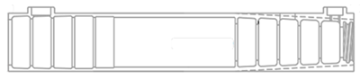 | The conical end is the prefabricated end, while the other end is the on-site assembly end. The outer surface of the conical segment is equipped with longitudinal ribs. |
| Boltops | Zheng [32] | 6.8~7.4 |  | The inner and outer diameters of sleeves used for vertical component connections are both larger than those of sleeves used for horizontal component connections. Sleeves used for horizontal component connections are equipped with bolts for fixing the reinforcing bars. | |||
| Tops joint |  | ||||||
| Taiwan Ruentex | Wu et al. [33] | 6.4 | 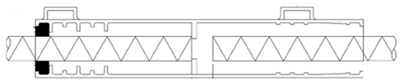 | The outer diameter of the sleeve is uniform along its entire length, and the internal structure features symmetrically arranged annular ribs. | |||
| JM sleeve | Wang [27] | Machining | 5.4~7.1 | 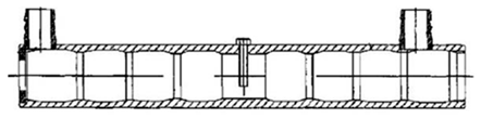 | The machine cuts continuous, bamboo-joint-like grooves on the inner side of the sleeve wall to serve as shear keys. | ||
| Special-shaped | Fuji sleeves | Gao [34] | Extrusion forming | 7.1~7.5 | 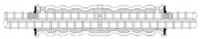 | The unique waveform structure is formed by squeezing the annular grooves distributed along the sleeve wall at intervals. | |
| Ordinary sleeve | Roundness | Type 1 | Einea et al. [28] | Bar splicing | 7 | 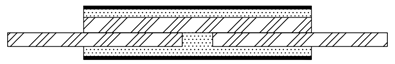 | The inner part of the sleeve is lapped with a steel bar. |
| Type 2 | Welded bar | 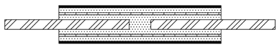 | Four steel bars are welded inside the sleeve. | ||||
| Type 3 | Welded steel ring | 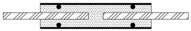 | Two steel rings are welded inside the sleeve. | ||||
| Type 4 | Welded steel plate | 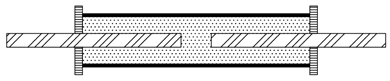 | Two steel plates are welded to the end of the steel pipe. | ||||
| Integral full-grouted sleeve | JG/T398-2019 [20] | Foundry technique | 8 | 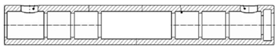 | The connection method is simple, and it offers high stability and safety. | ||
| Segmented full- grouted sleeve | Foundry technique + machining | 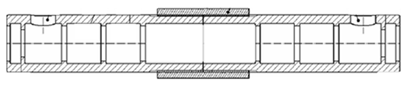 | The structure is simple, and the cost is lower compared to an integral full-grouted sleeve. However, the connection method is relatively complex and requires higher installation precision. | ||||
| HSS sleeve | Henin and Morcous [35] | Machining | 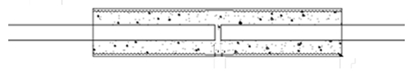 | HSS features threads machined on the inner wall of the sleeve to increase the bond strength between the grout and the sleeve. Type P, on the other hand, includes additional steel plates at the ends, which significantly enhance the tensile strength compared to HSS. | |||
| Type P |  | ||||||
| Pattern sleeve B | Kim [36] | Machining | 5~7.5 |  | The sleeve ends are designed with a tapered shape. | ||
| GWS | Lu et al. [37] | Welded connection | 6~6.4 | 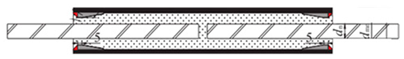 | A small-diameter steel pipe wedge is welded inside the sleeve. | ||
| GWST | Welded connection +machining | 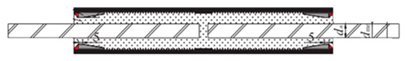 | A small-diameter steel pipe wedge is welded inside the sleeve, and the inner surface is machined with threads. | ||||
| Special-shaped | Square | Dai et al. [38] | extrusion process | 7.5 | 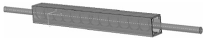 | The inner cavity is formed by cold pressing, creating threads or protrusions. | |
| Large-diameter threaded sleeve | Huang et al. [14] | Machining | 6.2 | 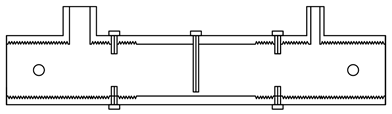 | Internal threads and bolts provide mechanical resistance. | ||
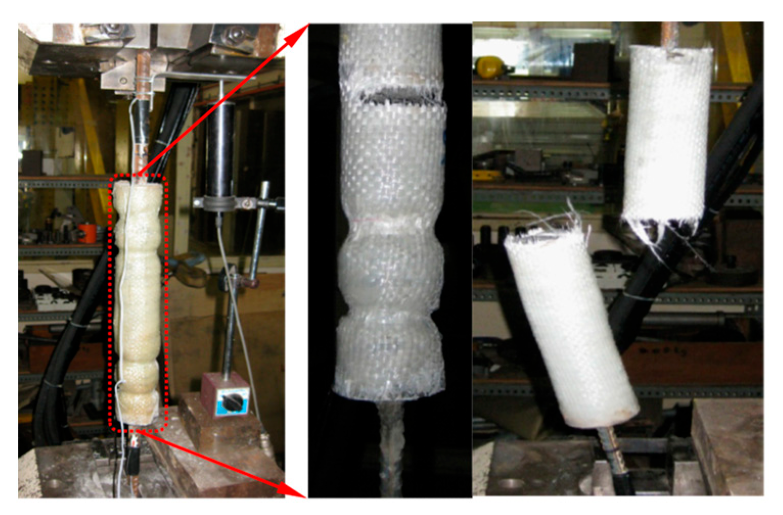
| GFRP sleeve | Sayadi et al. [39] | GFRP | 75~125 (mm) |  | Symmetrical conical ribs are set at both ends of the sleeve. | ||
| GDPS sleeve | Zheng et al. [40] | Rolling technique | 7 |  | The low-alloy seamless steel pipe is cold-processed using a three-axis roller compression technique. | ||
| Pattern sleeve A | Kim [36] | Machining + heat treatment | 5~7.5 | 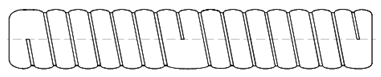 | The sleeve surface features continuous annular grooves. | ||
| THS | Ling et al. [41] | Foundry technique | 4.8~7.8 | 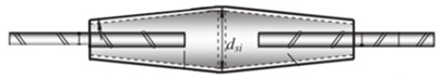 | The cylindrical sleeve tapers at both ends, presenting an overall conical shape. |
| Serial Number | Specimen Name | Anchorage Length/mm | Bar Diameter | Ultimate Tensile Strength | Yield Load Fy/kN | Ry ≥ 1.0 | Rs ≥ 1.25 | Rd ≥ 4.0 | Rc | fust/fstk | Failure Mode |
|---|---|---|---|---|---|---|---|---|---|---|---|
| 1 | WBS-5 [100] | 125 | 16 | 128 | 116.8 | 1.16 | 1.27 | 7.64 | 0.33 | / | Slip of steel bar |
| 2 | WBS-7 [100] | 175 | 16 | 133.5 | 113.8 | 1.13 | 1.33 | 13.13 | 0.45 | / | Fracture of steel bar |
| 3 | THS-5 [100] | 125 | 16 | 135.4 | 115.9 | 1.15 | 1.35 | 12.7 | 0.46 | / | |
| 4 | THS-7 [100] | 175 | 16 | 137.6 | 116.5 | 1.16 | 1.37 | 11.56 | 0.65 | / | |
| 5 | GW-D20-2 [37] | 140 | 20 | 182.7 | 140.25 | 1.12 | 1.45 | 5.21 | / | 1.08 | |
| 6 | GT-D20-2 [37] | 140 | 20 | 181.9 | 139.31 | 1.11 | 1.45 | 5.1 | / | 1.07 | |
| 7 | S57-400-28-G1-B1-5d [13] | 140 | 28 | 391.6 | 254 | 1.03 | 1.59 | 34.69 | 0.96 | 1.02 | |
| 8 | S57-500-28-G1-B1-5d [13] | 140 | 28 | 394 | 309.9 | 1.01 | 1.28 | 37.19 | 0.97 | 0.92 | |
| 9 | S48-t8-28-8d-G1-C2/2 [14] | 224 | 28 | 373.1 | / | 1.04 | 1.45 | 4.17 | 0.76 | 1.02 | |
| 10 | L350-18B-1 [101] | 170 | 12 | 78.9 | 74.6 | 1.2 | 1.34 | 2.65 | 1.05 | / | Grout slip |
| 11 | 3512-2R6 [39] | 170 | 12 | 78.94 | / | 1.28 | 1.44 | 2.2 | / | / |
Disclaimer/Publisher’s Note: The statements, opinions and data contained in all publications are solely those of the individual author(s) and contributor(s) and not of MDPI and/or the editor(s). MDPI and/or the editor(s) disclaim responsibility for any injury to people or property resulting from any ideas, methods, instructions or products referred to in the content. |
© 2025 by the authors. Licensee MDPI, Basel, Switzerland. This article is an open access article distributed under the terms and conditions of the Creative Commons Attribution (CC BY) license (https://creativecommons.org/licenses/by/4.0/).
Share and Cite
Long, Q.; Ding, M.; Huang, Z.; Ke, W.; Hu, Z. Research Status and Prospects of Grouted Sleeve Connections in Prefabricated Structures. Buildings 2025, 15, 1712. https://doi.org/10.3390/buildings15101712
Long Q, Ding M, Huang Z, Ke W, Hu Z. Research Status and Prospects of Grouted Sleeve Connections in Prefabricated Structures. Buildings. 2025; 15(10):1712. https://doi.org/10.3390/buildings15101712
Chicago/Turabian StyleLong, Qisheng, Mi Ding, Zhen Huang, Wenhao Ke, and Zhaojian Hu. 2025. "Research Status and Prospects of Grouted Sleeve Connections in Prefabricated Structures" Buildings 15, no. 10: 1712. https://doi.org/10.3390/buildings15101712
APA StyleLong, Q., Ding, M., Huang, Z., Ke, W., & Hu, Z. (2025). Research Status and Prospects of Grouted Sleeve Connections in Prefabricated Structures. Buildings, 15(10), 1712. https://doi.org/10.3390/buildings15101712