Article

Strength Characteristics of Polypropylene Fiber-Modified Rubber Foamed Concrete

1
School of Qilu Transportation, Shandong University, Jinan 250061, China
2
Qilu Expressway Co., Ltd., Jinan 250002, China
*
Author to whom correspondence should be addressed.
These authors contributed equally to this work and shared the first authorship.
Buildings 2025, 15(10), 1663; https://doi.org/10.3390/buildings15101663
Submission received: 8 April 2025 / Revised: 3 May 2025 / Accepted: 13 May 2025 / Published: 15 May 2025
(This article belongs to the Special Issue Research on Performance of Buildings Structures and Materials)

Abstract

To address the challenge of balancing static and dynamic strength in the engineering application of foam concrete, this study proposes a strategy to improve the static and dynamic mechanical properties of foam concrete by synergistically adding rubber particles and polypropylene fibers, and systematically analyzes the effects of rubber content, rubber particle size, and fiber content on the material’s compressive strength, flexural strength, and impact toughness. The results show that rubber enhances the dynamic strength of foam concrete through high elastic deformation, with a maximum increase of up to 200%. However, due to the obstruction of hydration reaction, the increase in rubber content reduces the compressive and flexural strength of foam concrete. Meanwhile, the influence of rubber particle size on static strength follows a parabolic trend, with the optimal overall performance achieved at a particle size of 20-mesh, resulting in an approximately 50% enhancement in compressive strength. The addition of fibers to form a three-dimensional mesh structure connecting the cement matrix and rubber particles to inhibit the expansion of cracks can effectively alleviate the deterioration of the static strength of foam concrete caused by rubber particles. The optimal fiber content is 0.2%. In addition, the fiber can also improve the dynamic strength of foam concrete. In addition, the mechanism behind the synergistic improvement of static and dynamic strength by rubber and fiber was summarized. Finally, the optimized proportion and the prediction formulas of static and dynamic strength are established for the above three strength indexes, and the accuracy of the prediction formulas can reach more than 90%.

1. Introduction

Foamed concrete (FC) is a typical low-impedance, lightweight porous material with good mechanical properties [1,2]. Because of its lightness, high rigidity, energy absorption, and other excellent characteristics [3,4], it has been successfully used in civil engineering, including roadbed backfill [5,6,7], bridge abutment backfill [8,9], tunnel seismic isolation [10,11], etc. In the context of engineering applications, the mechanical properties of foam concrete are of primary importance. In many cases, such as the roadbed backfill, the unconfined compressive strength is a crucial factor [12,13,14]. A reference to China’s standard [15] shows that the compressive strength of the foam–lightweight soil mixture utilized as a roadbed material must be no less than 0.8 MPa. In recent years, foamed concretes have found promisingly applications in anti-impact situations [16], e.g., roadside guardrails and downhill buffers. Under this condition, the dynamic mechanical properties of foam concrete should also be focused on [17,18,19].
Achieving a balance in static and dynamic strength is a problem worth considering. Many experiments found that the stiffness of traditional FC is relatively large, making it prone to damage under impact loading [20,21,22,23]. To improve the dynamic strength of foamed concretes, many scholars chose to add rubber to foamed concretes to improve the damping ratio and impact properties [24]. Bayraktar et al. [25] investigated the effect of cement and waste tire rubber as aggregates for FC. The results showed that the FC made with rubbers has energy absorption and abrasion resistance, which reduces its strength loss rate during load cycles. Eltayeb et al. [26] noticed that the relative sliding between the rubber particles and the cement matrix helps to absorb some of the energy to reduce the impact energy spreading and improve the impact resistance of the FC. In addition, rubber can enhance the toughness and water resistance of conventional FC [27,28]. In addition, the rubbers are usually recycled from scrap tires, realizing waste re-utilization [29]. Therefore, adding rubbers to foamed concrete is a good way to enhance the product’s impact resistance. However, rubber reduces the static strength of FC, such as flexural and compressive strength, because it decreases the cement content and hinders the bonding between cementitious matrixes [30].
On the other hand, studies have shown that the addition of fibers to foam concrete can effectively improve static strength. Examples include basalt fiber [31], polyamid fiber [32], hybrid natural fiber [33], and polypropylene fiber [34]. Among the various types of fibers, polypropylene fibers exhibited good performance in connecting the cemented matrix in foamed concretes [34,35,36]. For example, increasing fiber content was found to be capable of improving flexural toughness and controlling shrinkage cracking [37]. Polypropylene fibers are commonly used additives in FC [38,39,40]. Cai et al. [41] found that the moderate addition of polypropylene fiber increased the strength of foam concrete. The compressive and flexural strengths of products with fibers increased by 60.7% and 71.2%, respectively, compared to the FC without fibers. In addition, it was found that an optimum fiber content exists for fiber–foam concrete in terms of strength [42].
In summary, rubbers can improve the impact resistance of FC but reduce the static strength. The problem may be relieved slightly by adding fiber, which improves the static strength of the FC and slows down the development of cracks in the FC. Therefore, we hypothesize that the process of adding the polypropylene fiber and rubbers should consider both the static and dynamic strength. However, few studies concentrate on the strength characteristics of FC with the simultaneous addition of rubber particles and fibers. Ma et al. [43] incorporated both rubber particles and fibers into foam concrete, but his research focused on the dynamic elastic modulus of the material and failed to explain in detail the interaction mechanism between rubber and fiber inside the specimen. More importantly, there is a lack of a reasonable method for optimizing the rubber and fiber contents with consideration of the requirement of static or dynamic strength.
In order to find a way to improve the static and dynamic mechanical properties of foamed concrete simultaneously, based on the improvement effect of rubber and polypropylene fiber on foam concrete obtained from existing studies, this paper proposed the simultaneous addition of rubber and fiber to improve the static and dynamic strength of foam concrete. Based on the static and dynamic strength test and microscopic test, this paper firstly analyzed the effect of rubber content, rubber particle size, and fiber content on foam concrete, and then revealed the synergistic improvement mechanism of rubber and fiber on the static and dynamic strength; finally, this paper proposed the optimized proportion design and strength prediction formula of different ingredients.

2. Materials and Methods
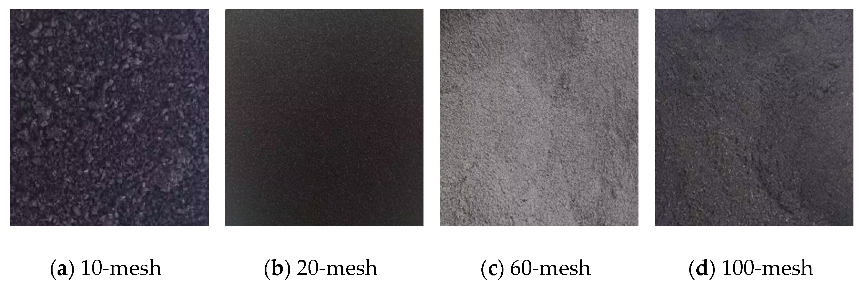
2.1. Materials

As a kind of porous lightweight concrete material, polypropylene fiber-modified rubber foamed concrete (PFRFC) is composed of cement, water, rubber, fiber and foam. These raw materials are introduced first.
Ordinary Portland cement, P.O 42.5, is used in the experiment. The rubbers used in this experiment to prepare the specimens are recycled from the waste tires. The whole tire was first crushed into 10-mesh (2 mm) rubber particles, and then ground into 20-mesh (0.85 mm), 60-mesh (0.25 mm) and 100-mesh (0.15 mm) rubber powders, respectively, as shown in Figure 1. This measure is adopted to investigate the influence of the rubber particles size on the strength of PFRFC. The rubber particle size range was selected based on the following consideration: 10–100-mesh is a common range for the industrial grinding of tires, covering typical products from coarse particles to fine powders, which is in line with the actual recycling process. Studies [30,44] found that 20–60-mesh particles are widely used for modifying concrete to balance the interfacial effect with mechanical properties. Fiber is a type of material, composed mainly of continuous or discontinuous filaments. Polypropylene fibers with a length of around 6 mm are used in the experiment. The main technical parameters for cement, rubber, and fiber are shown in Table 1. The preparation of foam involves the dilution of the foam agent and water in a 1:40 ratio to obtain the diluted liquid. Then, the diluted liquid is converted into stable foam using a foaming machine. Finally, the foam with a density of 50 kg/m3 is acquired.

2.2. Mix Design of the Experiment Specimen

The mixing design of PFRFC was carried out with reference to the Chinese Standard [43]. The calculation steps are as follows:
Firstly, Equations (1)–(4) can be employed to calculate the quantity of cement, rubber, and water.
M c = 1 ρ c + b 1 1 α 1000 + α ρ r 1 α
M r = α 1 α M c
M w = b M c 1 α
R L = M c + M r + M w
where Mc, Mr, and Mw are the mass of cement, rubber, and water per admixture volume of cement slurry, respectively; RL is the wet density of the cement slurry (kg/m3); b is the water-to-solid ratio (the ratio of water mass to the mass of all solid material); α is the percentage of rubber in the cement slurry relative to the mass of cement; ρc is the density of cement; and ρr is the density of the rubber particle. To satisfy the demand of flow value (160~190 mm), the b value in this paper was set as 0.45.
Thereafter, the amount of the foam was calculated using Equation (5). The raw material requirement was recalculated for the single specimen after the addition of foam, and the mass of the cement, rubber, and water in a single specimen after the addition of the foam was calculated using Equation (6).
λ = R L R f w R L ρ a
m i = M i 1 λ
where Rfw is the target wet density (kg/m3); λ is the bubble rate of the foamed concrete; ρa is the density of the foam (kg/m3); m i represents m c , m r and m w respectively; and M i represents M c , M r and M w respectively. Finally, the amount of fiber was calculated by Equation (7); Daneti et al. [37] pointed out that fiber content greater than 0.3% leads to agglomeration, which results in lower strength and affects casting density. Thus, a lower content was chosen to balance dispersion and reinforcement. Therefore, polypropylene fiber contents of 0.1%, 0.2%, and 0.3% were selected.
m f = μ ρ f
where m f is the mass of fiber per admixture volume of cement slurry (kg/m3); μ is the volumetric fiber content; and ρf is the density of the fiber (kg/m3).
The effect of sample density has been investigated by many studies [45,46,47]. In these, the increase in density improved the strength of foamed concretes. Accordingly, the influence of density to the PFRFC is not detailed any more in this study. In this paper, a common wet density value of 700 kg/m3 is selected as a representative sample. Correspondingly, the mass of each material per admixture volume of cement slurry for different rubber and fiber contents is shown in Table 2.

2.3. Preparation of the Specimen

The process of specimen preparation is presented in Figure 2. First, molds with different shapes are prepared according to different test types. In order to ensure the integrity of the specimen, molds should be coated with engine oil. Secondly, the foam agent and water are diluted at the volumetric ratio of 1:40, and only those foams with a density error of less than 5% (665–735 kg/m3) can be used. Next, it is necessary to mix the cement, water, rubber, and fiber together to obtain the basic paste. Then, the foamed concrete slurry is produced by adding preformed foam to a basic paste. Once the slurry has been obtained, it is necessary to determine its flow value. Only slurries with a flow value between 160 mm and 190 mm can be poured into the molds. The molds poured with the slurries are attached with cling wraps and put into the standard curing room for 7 days; the curing temperature is 20 ± 2 °C and relative humidity is more than 95%. Then, the demolding process is conducted. Finally, the specimens are weighed and put into the sealed bags in the standard curing room until 28 days from the start of the experiment.

2.4. Test Methods

In this section, the specimens are customized according to the different test conditions. Three variables are investigated in the experiment: rubber content (5%, 10%, 15%, 20%), rubber particle size (100-mesh, 60-mesh, 20-mesh, 1–3 mm), and fiber content (0%, 0.1%, 0.2%, 0.3%). The cases to be tested are depicted in Table 3, with a total of 4*4*4 = 64 experiments. At the same time, ordinary FC, prepared by mixing only cement, foam and water, is set as the control group. The wet density of the control specimen is also 700 kg/m3.

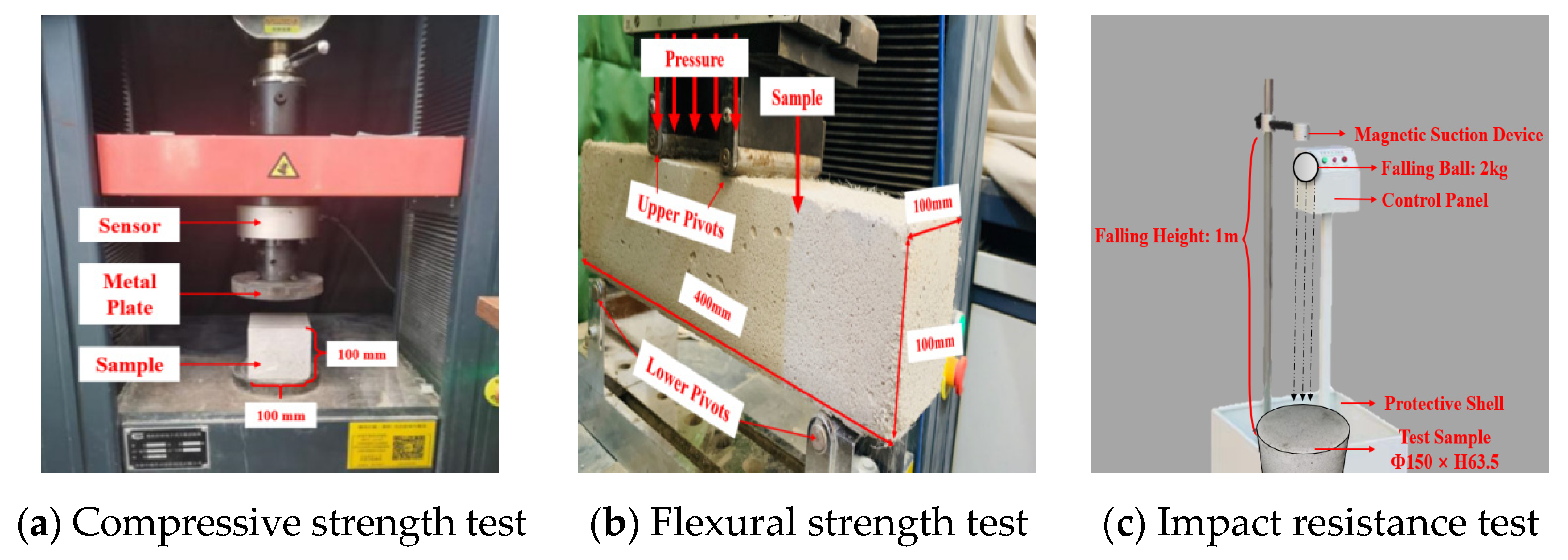
2.5. Static and Dynamic Strength Tests

The static and dynamic strength tests include compressive strength tests, flexural strength tests, and impact resistance tests, as shown in Figure 3.
The compressive strength test is conducted according to the Chinese Standard [48]. In the test process, three specimens are selected for parallel tests with the size of 100 × 100 × 100. During each test, one specimen is placed under the metal plate of the universal testing machine, which uniformly applies pressure to the specimen at a speed of 1.5 kN/s until the specimen exhibits failure. At the same time, the load corresponding to the specimen failure is recorded and the compressive strength is measured by averaging the three load values.
The flexural strength refers to the ultimate failure stress per unit area of a material under a bending moment. The flexural strength test is conducted according to the Chinese Standard [48]. In the test process, three prismatic specimens with flat surfaces are selected for three tests and the size is set to 100 × 100 × 400 mm. The four-point bending test is adopted, and the intervals of the upper and lower pivots are set to 300 mm and 100 mm, respectively. During each test, the universal testing machine is used to uniformly apply pressure to the specimen at a speed of 1.5 kN/s until specimen failure. At the same time, the load corresponding to the specimen failure is recorded and the flexural strength is measured by averaging the three load values.
The impact resistance of foamed concretes can be measured by the number of dynamic blows [49]. For this purpose, we designed customized equipment for examining impact resistance to quantify the dynamic mechanical properties of PFRFC. The equipment consists of a control panel, a magnetic suction device, a steel ball, and a protective shell. During the test, a 2 kg steel ball is placed by a magnetic suction device at a height of 1 m above the specimen and released by the control panel to fall freely onto the surface of the specimen. The impact energy of the specimen can be calculated as 19.6 J according to Equation (8), where E is the impact energy (J); m is the mass of the steel ball (kg); g is the acceleration of gravity (m/s2); and h is the height of fall (m). The surface and bottom of the specimen were checked for cracks after each fall. The number of times the first specimen cracked was recorded, the number of falls was utilized to indicate the impact resistance of the specimen, and three repetitions of the specimen were recorded to give an average result.
E = m g h  

2.6. Scanning Electron Microscope (SEM) Test

Moreover, the Scanning Electron Microscope (SEM) can be employed to ascertain the air–void structure of PFRFC [50]. Subsequently, the specimens were reduced to a 10 mm × 10 mm × 10 mm cube and placed into a dispensing bottle containing anhydrous ethanol. Five images of each specimen were captured from disparate positions using an electron microscope, with the pores magnified 30–45 times. These images were then processed using Image Pro Plus 6.0 to determine the average diameter. The software was capable of calculating the pore size, area, and pore distribution of foamed concrete.

3. Results and Discussion

In this section, the effects of rubber content, rubber particle size, and fiber content on the static and dynamic strength of PFRFC will be discussed separately. Then, the mechanism of two additives is explained through a micro-level perspective.

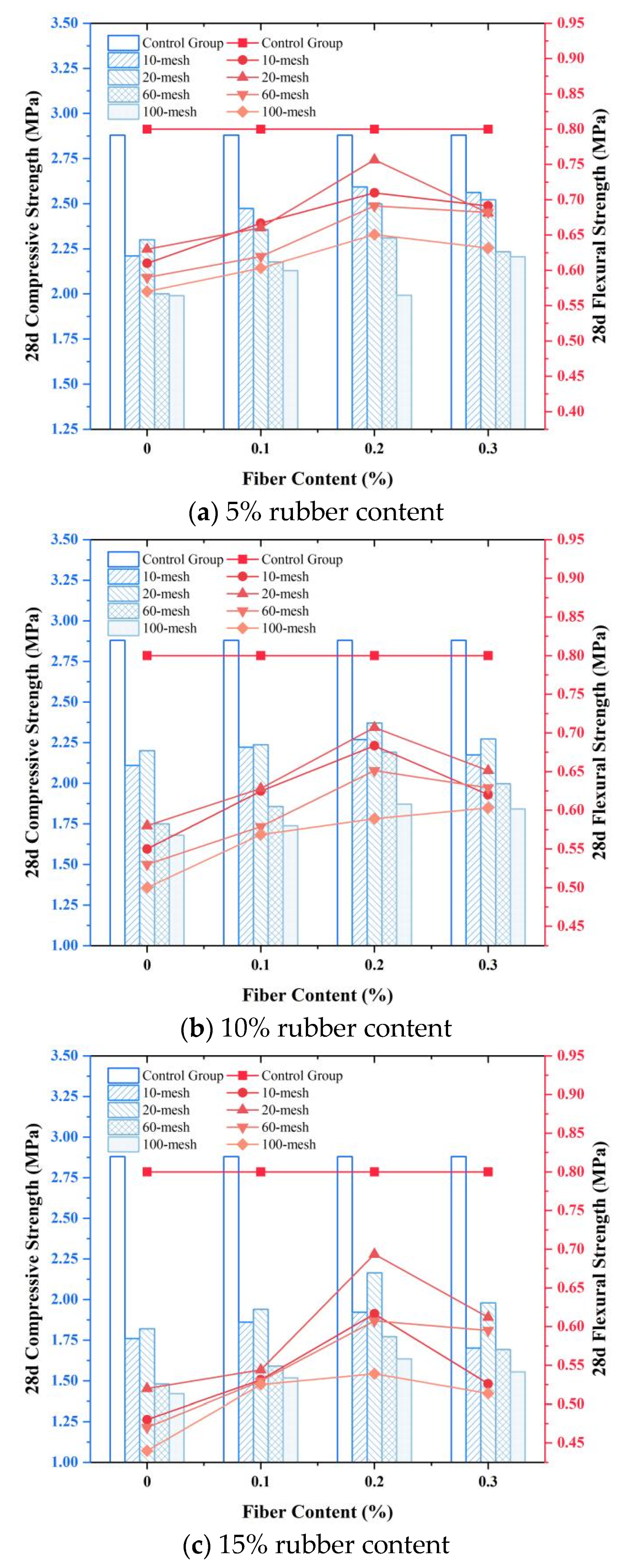
3.1. Analysis of Static Strength

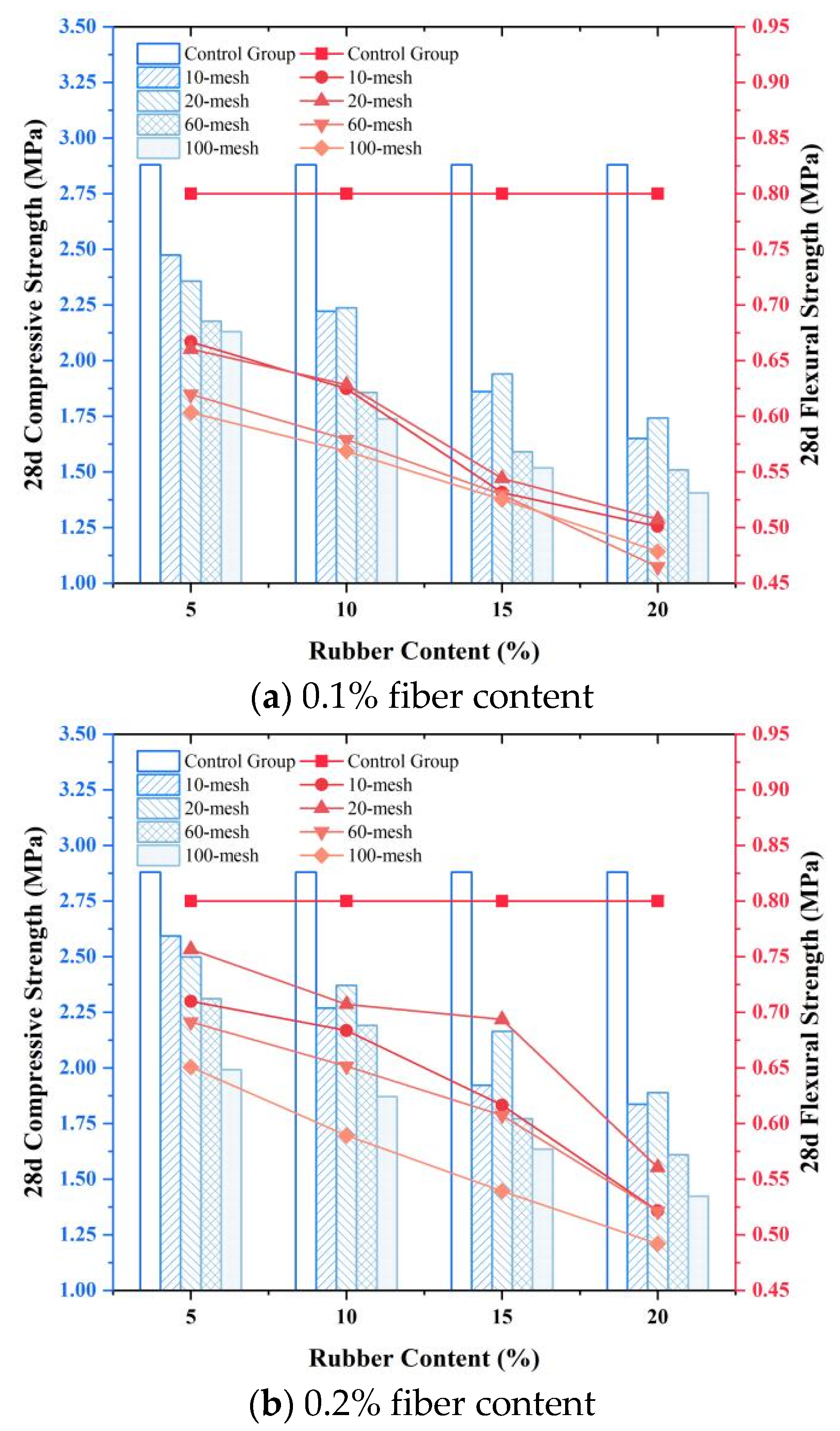
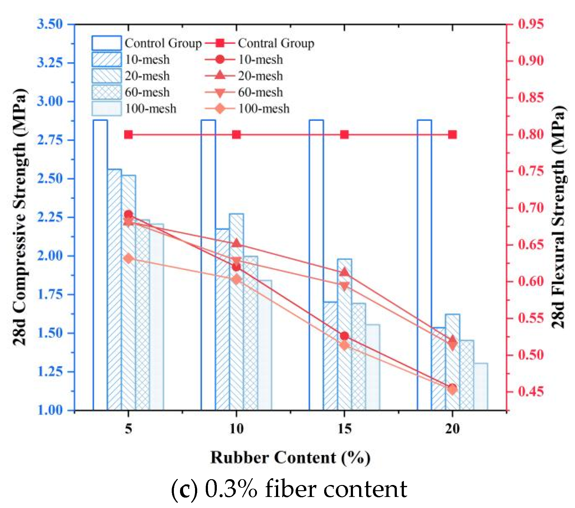
3.1.1. Effect of Rubber Content

Taking the rubber content as the variable, the compressive strength and the flexural strength of PFRFC are shown in Figure 4. Compared with the control group, the strength of PFRFC reduced a lot. The compressive strength exhibited a decreasing tendency in relation to the rubber content. The decrease rate ranges from 4.6% to 29.1%, relating to the particle size of rubbers. Similarly, flexural strength demonstrated a gradual decline with the rising rubber content shown in Figure 4, including a decrease rate changing between 2.0% and 27.7%. Therefore, the incorporation of rubber particles resulted in a reduction in the static strength of PFRFC, and the reduction rate also increased with the rubber content.
After adding only rubber particles to the concrete, Wang et al. [30] and Ji et al. [51] also observed a decrease in the compressive strength of the specimens with increasing rubber content, which was similar to the decrease in the compressive strength of PFRFC. This decrease can be attributed to the reduction in cement content. As concluded by Liu et al. [23], the hydration of cement plays a primary role in determining the strength of foamed concrete. However, when the rubber is used to replace a some cement, the strength of foamed concrete is inevitably reduced, particularly when the percentage of rubber content is high. In addition, the rubber might slightly destabilize the foam [52], and the gas-inducing attributes of the rubber particles enhance the porosity of the PFRFC [44,53], which also causes a reduction in the overall compactness and strength of the specimen. A comparison of existing studies [44,53] revealed that the strength of PFRFC is greater than that of rubber-only FC, which is due to the fact that the dispersion of fibers helps the rubber particles to be uniformly distributed in the matrix and avoids localized weakened regions caused by the aggregation of rubber particles. Consequently, the results of the static tests demonstrate that, in the field of PFRFC engineering, if the primary concern is the static strength, the content of rubber particles should not exceed 15%.
Under the action of pressure, the top surface of the specimen shows a concave trend and thus the bottom is stretched, as shown in Figure 5a. Because of the low tensile strength of PFRFC, cracks mostly appear from the bottom and develop through the whole specimen. At the same time, the rubber inside the specimen can produce large deformation to absorb the upper load and thus yield shear failure of the cement matrix on both sides of the rubber, resulting in oblique cracks, as shown in Figure 5b. The deformation of the rubber is greater than the deformation of the cementitious matrix in the FC. Due to the inconsistency of the deformations, the contact position between the rubber and the cementitious matrix in the specimen is prone to turn into a fracture [54].

3.1.2. Effect of Rubber Particles Size

The variations in compressive and flexural strength as a function of rubber particle size are illustrated in Figure 6. The subplots in Figure 6 show that, in most cases, the compressive and flexural strength firstly increase to the peak values and then decrease with the increasing rubber particle size. The peak strength occurs with the 20-mesh rubber particle size. The strength descends in order 20-mesh > 10-mesh > 60-mesh > 100-mesh for most experiments. However, some special cases, as seen in Figure 6a, for example, do not present the peak values. It is most likely that the experimental discreteness or the range of rubber particle size (100- to 10-mesh) did not allow the sample with 5% rubber content to reach peak strength. More evidence for the optimal rubber size 20-mesh is found in Ma et al. [43], whose experiments also proved that the rubber particle size has an optimal value.
The additional rubber, although not directly involved in the hydration reaction, assists in the formation of a solid skeleton, and larger particles are more likely to form a stable skeleton. Consequently, when the particles size is between 100- and 20-mesh, the strength increases with growth in the size of particles [53]. However, the incorporation of excessively large particles into the cementitious materials may result in a rubber-based polymer, which could potentially impede the interconnection of the cementitious materials, thereby reducing the overall strength of the material [54]. This leads to a decrease in compressive and flexural strength. In addition to determining the optimal rubber particle size, this study contrasted the compressive strength results from prior research [54] involving exclusive rubber particle incorporation, in which the compressive strength of foamed concrete containing 40-mesh rubber particles was measured at merely 1 MPa under a 10% rubber content condition, which is 55–60% lower than that of 20-mesh PFRFC and 52–55% lower than its 60-mesh counterpart. It shows that fibers can mitigate the strength decrease caused by a large particle size, which is due to the fact that fibers improve matrix compactness by filling the undesirable pores of large rubber particles due to their irregular shape and enhancing the slurry fluidity.

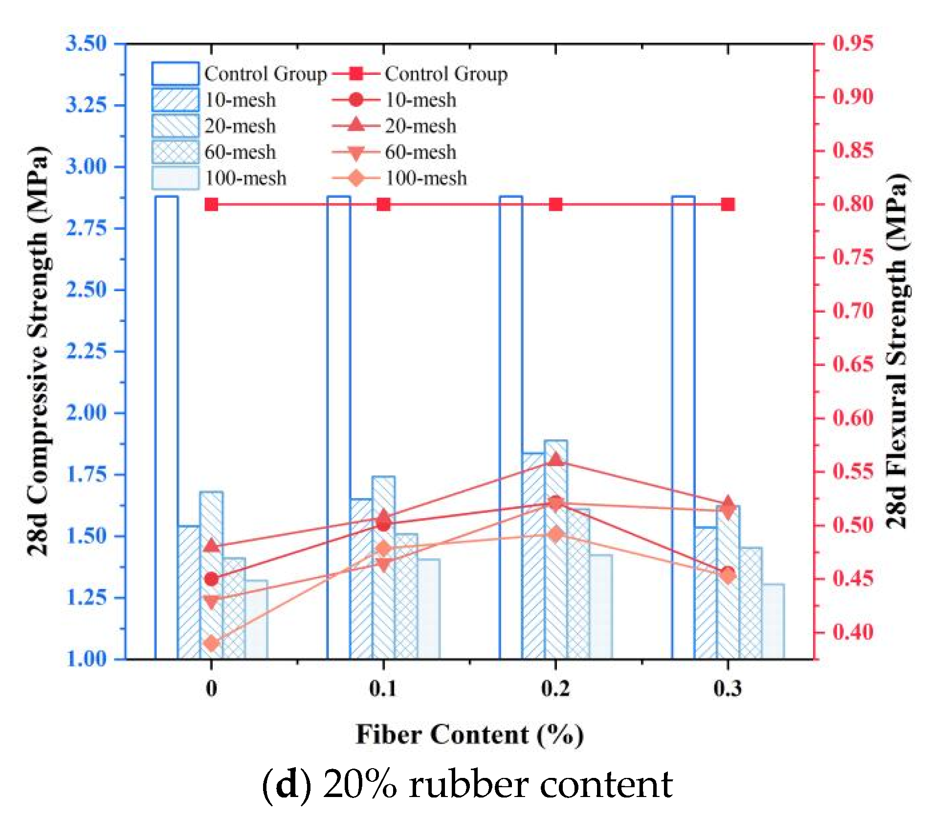
3.1.3. Effect of Polypropylene Fiber Content

Figure 7 shows the variation in the static strength of PFRFC with different polypropylene fiber contents. Compared to the samples with rubber but no fiber (fiber content 0%), the addition of fiber achieved an improvement in the compressive and flexural strength. This finding is consistent with the results of previous studies [34,35,36]. However, the compressive and flexural strengths with the rubber and fiber are still lower than those of the control group (both no rubber and fiber). Figure 7 shows that as the fiber content increases from 0% to 0.3%, the compressive strength of PFRFC shows a roughly parabolic trend, with the maximum compressive and flexural strength obtained at 0.2% fiber content. More specifically, under the same conditions of rubber particle size and content, the compressive and flexural strengths of PFRFC with 0.2% fiber content exhibit an increase of approximately 1.2% to 15% and 1.3% to 27.5%, respectively, in comparison to those with 0.1% and 0.3% fiber content. Correspondingly, Figure 7 revealed that the 0.2% fiber content was optimal in terms of static strength.
As can be seen in Figure 7, the compressive and flexural strength of PFRFC increased when the fiber content increased from 0% to 0.2%, indicating that the fibers were added to mitigate the static strength deterioration induced by the rubber. On the one hand, the polypropylene fibers are capable of improving toughness and hindering the development of cracks. On the other hand, the fibers show strong adsorption to the cement matrix [37,38], which can improve the poor adhesion interface between the rubber and cement matrix.
However, when the fiber content continues to increase, it becomes difficult to uniformly disperse fibers during specimen preparation, and aggregated fibers may cause stress concentrations when the specimen is subjected to stress. A study by Ren et al. [55] revealed that the agglomeration of fibers resulting from poor dispersion can lead to a weakening of the bond between the fibers and the hydration products. This caused a decrease in the compressive strength of PFRFC with 0.3% fiber content in Figure 7, indicating that excessively high fiber content will weaken the strength mitigation mechanism of polypropylene fibers in terms of rubber. Therefore, the fiber content should be controlled at around 0.2%.
The failure form in flexural strength in products containing fibers is illustrated in Figure 8. By comparing the cracks with those without fibers, it can be seen that only one fine crack extends from the bottom to the top after fiber blending. This is due to the fact that specimens containing fibers are effective in hindering the development of cracks. When subjected to loading, cracks are created by disrupting the three-dimensional mesh structure consisting of fibers and cement matrix. This structure has the ability to increase toughness and retard cracking. Then, following the occurrence of cracking, the cement matrix at both ends of the cracks can still be connected by the fibers. Therefore, the development of the cracks needs to overcome the friction between fibers and the cement matrix, as well as the tensile resistance of the fibers themselves.

3.2. Analysis of Dynamic Strength

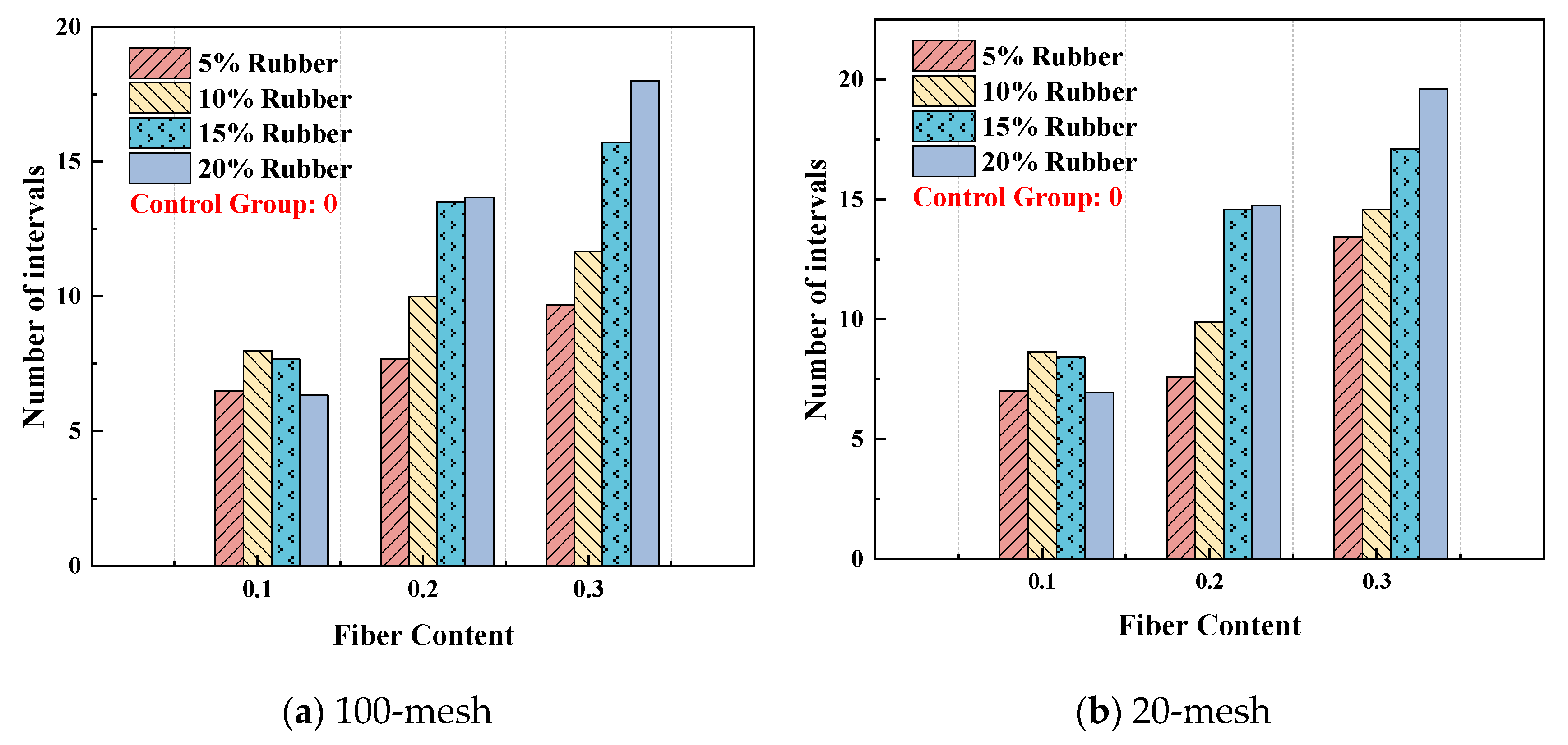
3.2.1. Effect of Rubber Content

The experimental results of the impact resistance test with different rubber contents are shown in Figure 9. As can be found, the impact resistance increases linearly with the rubber content. Compared to the control FC specimens, when the rubber content increased from 5% to 20%, the number of maximum ball drops increased by 85%, 121%, 164%, and 200%, respectively. This proves that the impact resistance of FC mixed with rubber particles is obviously enhanced. Eltayeb et al. [26] also arrived at similar experimental results and attributed the improvement in impact resistance to the ability of the rubber particles to absorb impact energy due to their ductility. Moreover, when the specimens were subjected to an impact load, the relative sliding between the rubber particles and the cement matrix helped to absorb some of the energy, reducing the spread of impact energy and increasing the impact resistance of the PFRFC.
In addition, the experiments show that when the rubber content is small, the iron ball will rebound to a certain height after falling onto the specimen. However, when the rubber content is relatively large, the iron ball falling onto the specimen basically does not rebound. This indicates that the addition of rubber particles improves the plasticity of PFRFC and increases its deformation capacity. Therefore, PFRFC has significant energy absorption and shock absorption effects.

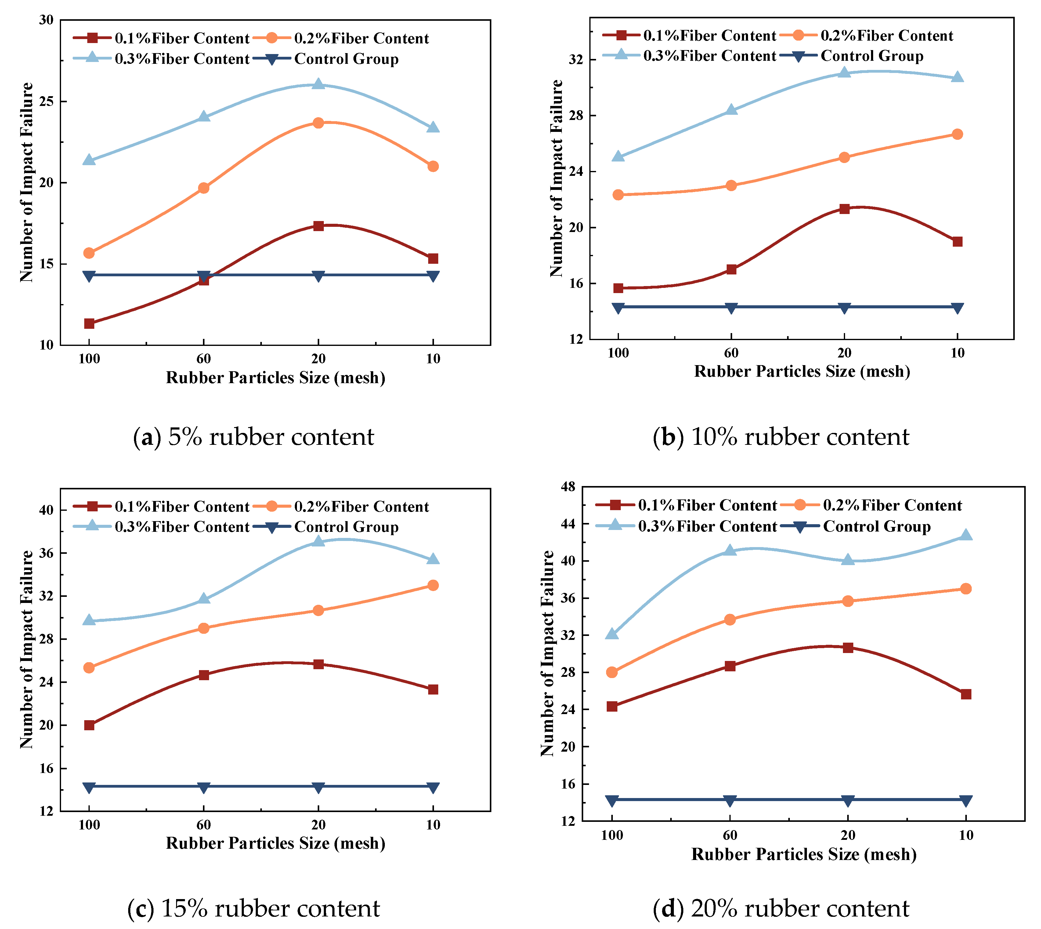
3.2.2. Effect of Rubber Particles Size

Figure 10 presents the impact resistance of the specimen under different rubber particle sizes. In general cases, PFRFC with 20-mesh rubber particle size achieves the best impact resistance, followed by 1–3 mm, 60-mesh, and 100-mesh varieties, and the maximum increase can be 1.75-fold. The unit allowable deformation capacity of 20-mesh rubber particles is stronger, and the distribution is relatively more uniform. As the rubber particle size increases, the non-uniform contact area rises further, and the frictional resistance between the cement and the rubber increases [56,57]. This results in an increase in the damping ratio of the PFRFC. However, when the particle size increases to 10-mesh, the uneven contact area between rubber particles and cementitious materials is too large. The rubber particles tend to separate from the cementitious material during impact loading, and the reduction in friction between the cement and the rubber leads to a decrease in the damping ratio of the PFRFC. Consequently, the impact resistance of the specimen is reduced.

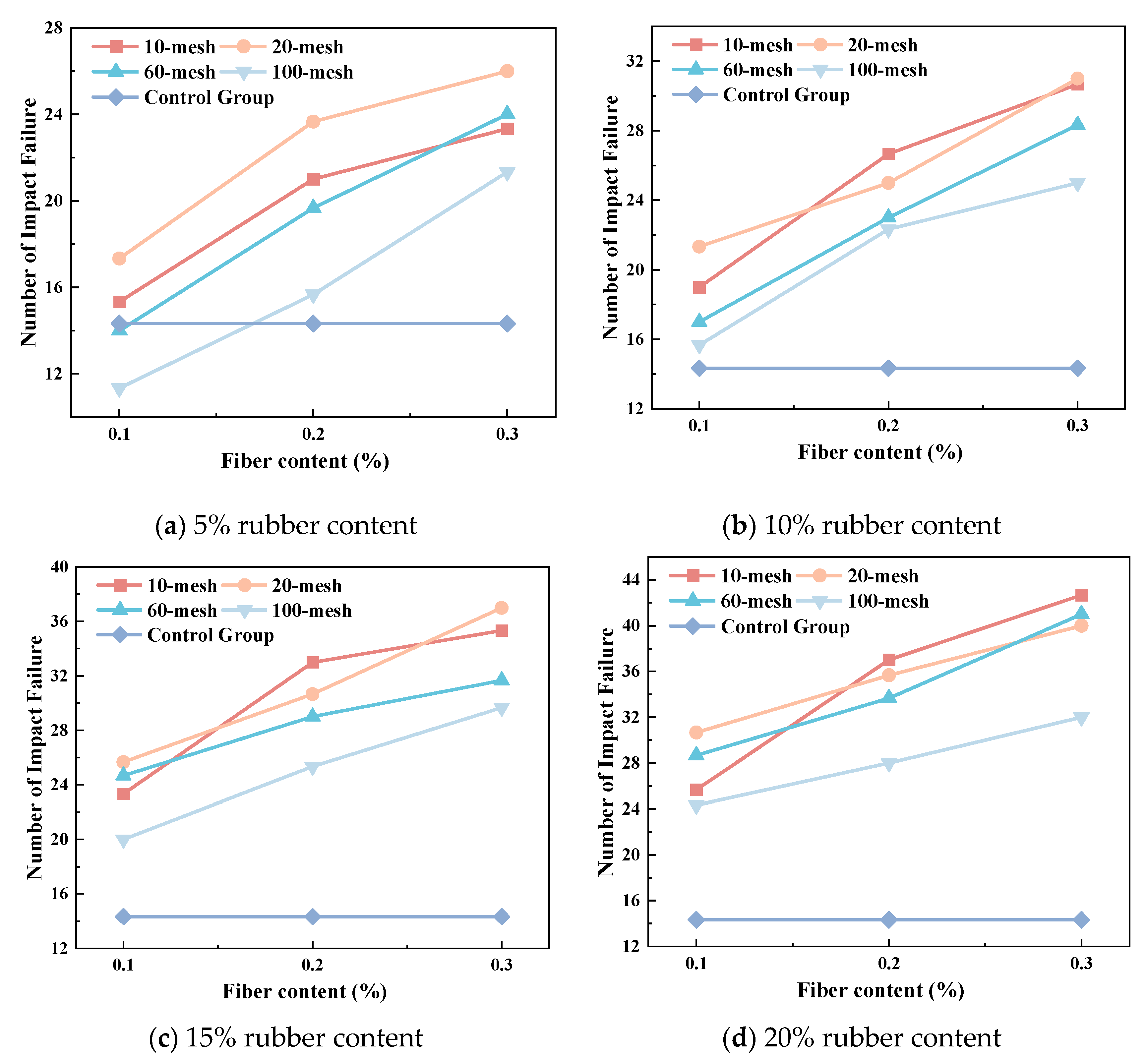
3.2.3. Effect of Polypropylene Fiber Content

Figure 11 shows the changes in the impact resistance of PFRFC specimen with different fiber contents. It can be found that the impact resistance of PFRFC increases approximately linearly with the increase in fiber content. The impact resistance of the fiber-containing specimens is 1.1–2.7 times higher than that of the control group, which is consistent with the findings of Niu et al. [58]. This illustrates that the addition of fiber could effectively improve the impact resistance of PFRFC.
The number of dropped balls between the first crack in the specimen and the specimen’s failure are presented in Figure 12 to further illustrate the role of fiber. This figure demonstrates that the control specimen fractures immediately upon the emergence of a crack, whereas the specimen containing fibers persists after cracking due to the connecting effect of the fibers. This outcome substantiates the assertion that fibers possess the capacity for enhanced toughness and delayed cracking.
Figure 13 shows that the specimens without fibers were easily fractured and had large crack widths, while the PFRFC specimens containing 10% 20-mesh rubber and 0.3% polypropylene fibers cracked only slightly or continuously after impact damage, indicating that the toughness of the fibers played an important connecting role. The fibers exhibit favorable tensile characteristics and are distributed in a three-dimensional mesh within the PFRFC structure. This configuration enables the fibers to effectively absorb impact energy and impede the propagation of cracks.

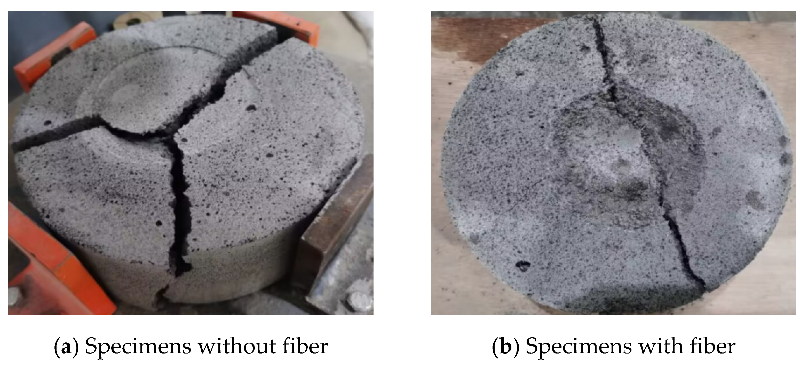
3.3. Micro-Structures

The SEM results are presented in Figure 14 and Figure 15. As illustrated in Figure 14a,b, pore structures are formed around the rubber particles, and the arrangement of these pore structures is uniform as the rubber particle size increases. As the rubber particle size increases from 60-mesh to 20-mesh, it can be postulated that the rubber particles form a backbone structure, thereby enhancing the strength of the pore structure. Consequently, the compressive and flexural strengths of the material also increase. However, when the particle size increased to 10-mesh, shown in Figure 14c, the uniformity of the pore structure diminished, and micro-cracks emerged around the larger rubber particles. This suggests that at this stage, the bonding of the cement matrix was impeded by the substantial dimensions of the rubber particles, which subsequently resulted in a decline in the compressive and flexural strengths. Furthermore, micro-cracks at the bond interface between rubber and cement are evident in Figure 14c. The presence of micro-cracks resulted in a reduction in the static strength of the material. Conversely, an increase in rubber content resulted in an enhancement of the dynamic strength of PFRFC due to its capacity to absorb energy.
Figure 15 demonstrates the microscopic scan results of PFRFC with varying fiber content. As the fiber content increased, the micropores surrounding the fibers grew in number and size, and the distribution of the pore structure became irregular. This phenomenon, known as the “agglomeration” of fiber, affects the pore structure and explains the observed decrease in the static strength of PFRFC as the fiber content increased from 0.2% to 0.3%. This provides an explanation for the observed decrease in the static strength of PFRFC when the fiber content is increased from 0.2% to 0.3%. Meanwhile, as observed in Figure 15a, the fibers assume a three-dimensional mesh structure along the direction of the blue dashed line. This structure enhances the integrity of the foam concrete material, improves the damping ratio of the foam concrete material under dynamic loading, and acts as a vibration damper, thereby increasing the impact resistance of PFRFC with increasing fiber content.

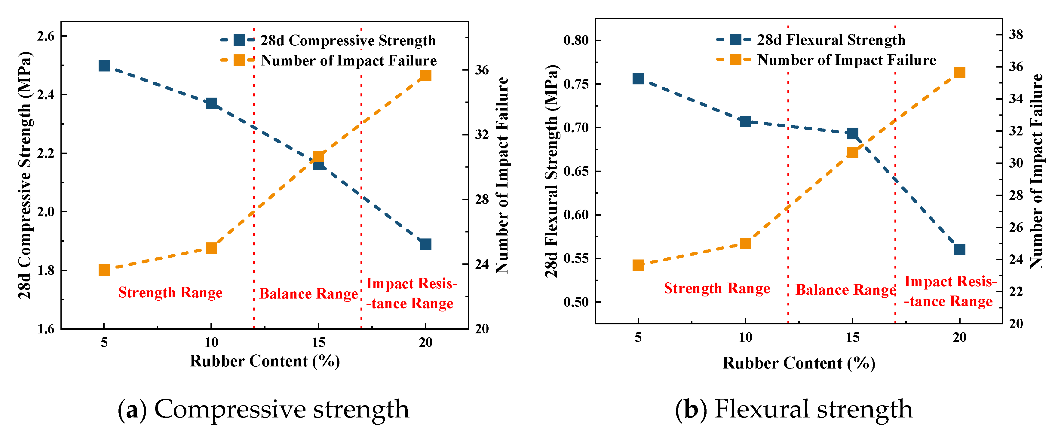
3.4. Optimized Component Proportion Design

After investigating the effect of rubber content, rubber particle size, and fiber content, this section aims to recommend an optimal mix design to provide references for various practical conditions. First, the rubber particle size should be 20-mesh as it corresponds to the optimal compressive and flexural strength, as well as the best impact resistance. Then, the fiber content should be 0.2% as it provides the best static strength. Continuously increasing the fiber content may reduce the workability [59] and increase the cost, although it can improve the impact resistance. Finally, the key point is the rubber content as it can decrease static strength but increase impact resistance. Under this condition, we used the “balance zone method” proposed by the authors [1] to satisfy various conditions. As shown in Figure 16, we plot the compressive or flexural strength versus the impact resistance in one figure. These strengths are divided into three ranges based on the rubber content: 5–12% for static strength, 12–17% for balance, and 17–20% for impact resistance. The classification is based on the intersection of the curves, from left to right, according to the amount of rubber content.
When the rubber content is in the “static strength” range (5% to 12%), the 28d compressive strength of PFRFC is greater than or equal to 2.25 MPa, while the 28d flexural strength is greater than or equal to 0.7 MPa. If the engineering project has a requirement for static strength but not for impact performance, it is recommended that the rubber content be maintained within the strength range. When the rubber content is in the impact resistance range, the static strength of PFRFC is slightly lower but the impact resistance performs very well. A rubber content larger than 17% is recommended when the PFRFC is used in some impact conditions like anti-collision guardrail.
In the case of a project that requires the 28d compressive strength of PFRFC to be greater than or equal to 2 MPa and the 28d flexural strength of PFRFC to be greater than or equal to 0.6 MPa, and where there are high requirements for vibration-damping performance, it would be advisable to select the rubber mixing amount of PFRFC from the balance range (12–17%).

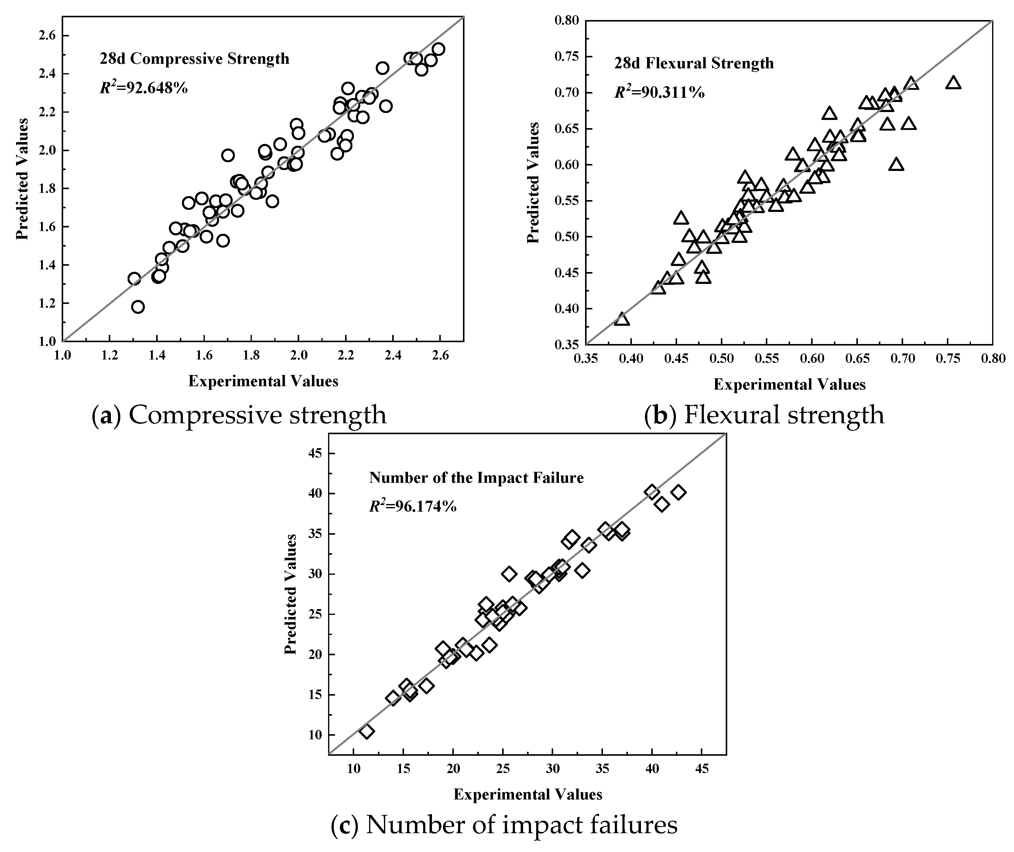
3.5. Prediction of Static and Dynamic Strength

According to the experimental results, we can establish the prediction model of the compressive and flexural strength, as well as the impact resistance. The prediction equations for compressive strength, flexural strength, and impact resistance of PFRFC are established as shown in Equations (9)–(11).
f c = 4.981 x r + 7.0677 x s 100 2 5.1779 x s 100 5.36522 ( 100 x f ) 2 + 2.10194 100 x f + 2.6235
f c t = 1.134 x r 9.0511 x s 100 2 + 0.356 x s 100 2.2264 ( 1000 x f ) 2 + 0.94493 100 x f + 0.66515
N P F R F C = 9.30 10 x r 8.1418 x s 100 2 + 2.7091 x s 100 + 5.0833 1000 x f + 6.1386
where f c and f c t are the 28d compressive and flexural strength of PFRFC (MPa), respectively; N P F R F C is the number of impact failures of PFRFC; and x r , x s , and x f are the values of rubber content (%), rubber particles size (mesh) and fiber content (%), respectively.
Accordingly, the predictions versus the experimental values regarding compressive strength, flexural strength, and impact resistance are shown in Figure 17. These empirical equations correspond to coefficients of determination (R2) of 92.648%, 90.311%, and 96.174%, respectively, indicating that the prediction equations are all able to fit more than 90% of experimental data and thus demonstrating a high degree of reliability. It should be mentioned that these empirical equations are only available for the PFRFC with a wet density of 700 kg/m3. For other densities, these equations may need to multiply an augment coefficient, but this requires more experimental data and is out of the scope of this paper.

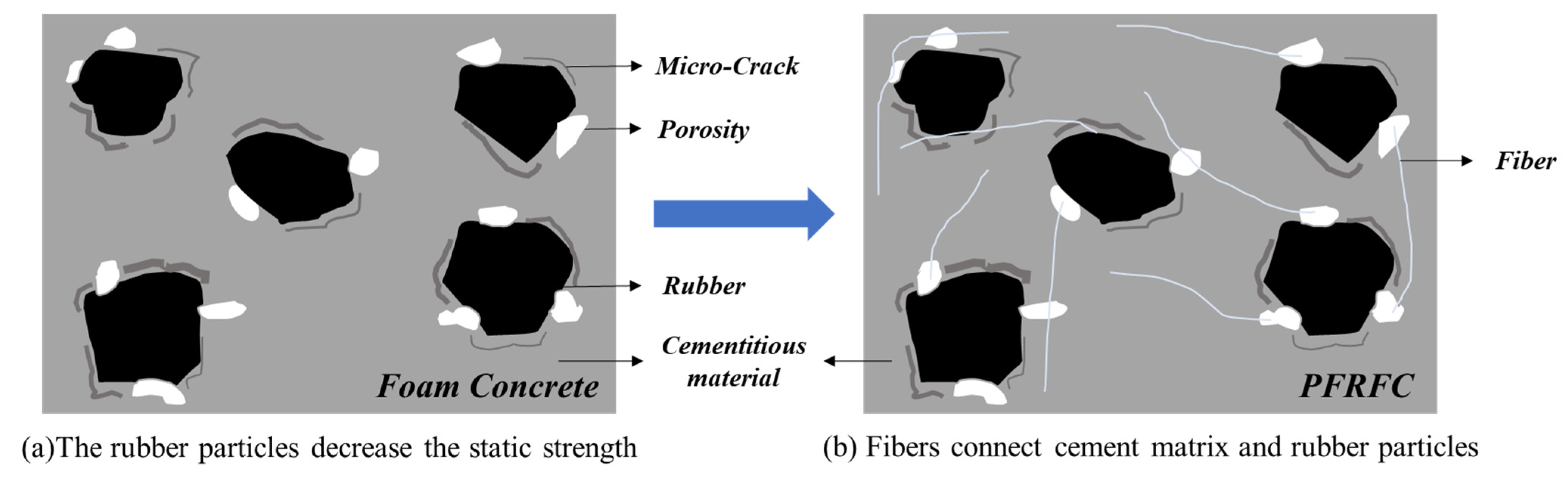
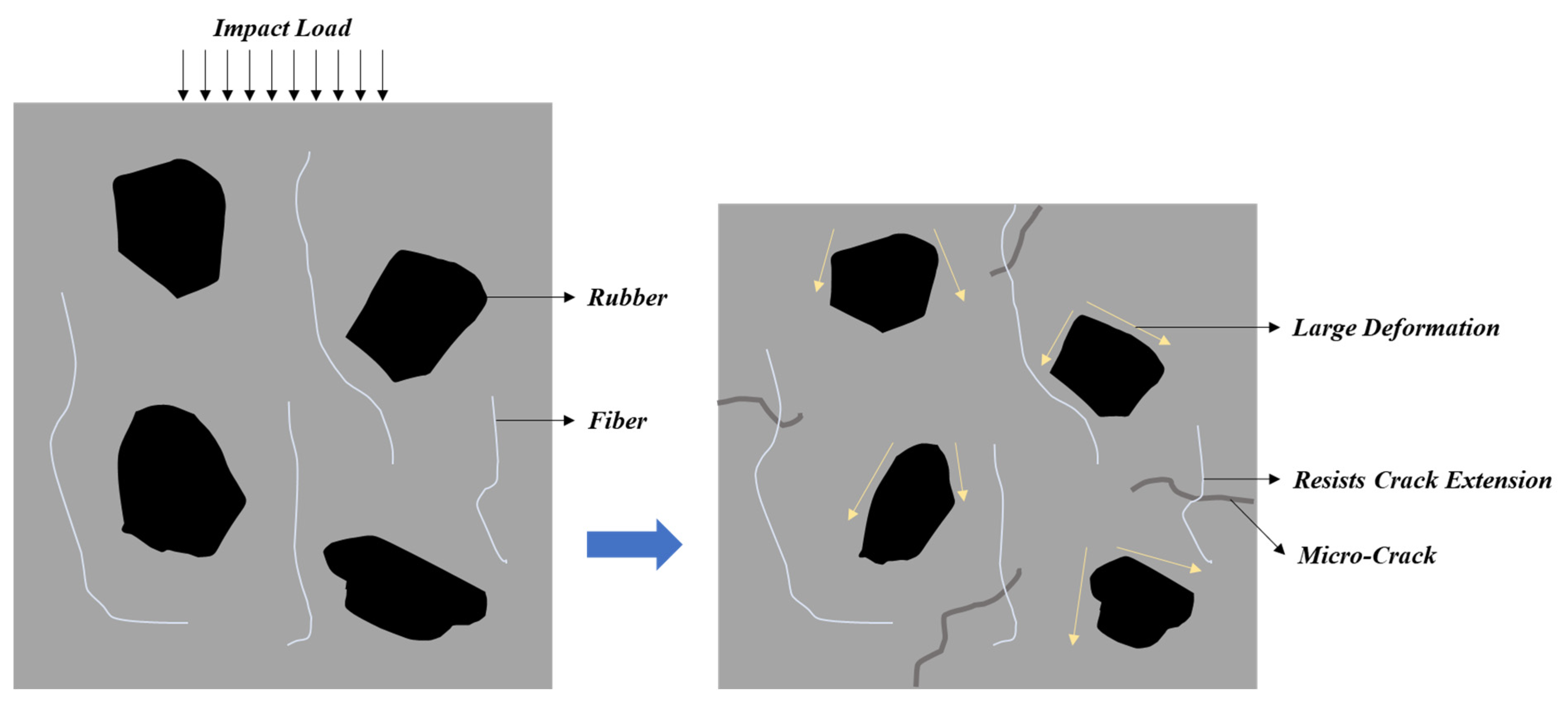
3.6. Mechanism of Synergistic Improvement of Mechanical Strength Between Rubber and Fiber

(1) Mitigation of adverse effects on static strength
As shown in Figure 18a, the rubber particles reduce the cementitious material content after replacing part of the cement and hinder the effective encapsulation of the cement paste, resulting in the existence of micro-cracks and pores in the interface zone, which leads to the decrease in compressive and flexural strength with the increase in rubber content. The fibers are uniformly dispersed to form a mesh skeleton, bridging the cement matrix and rubber particles, limiting the deformation of the matrix, and hindering the initial formation and expansion of cracks, as shown in Figure 18b. However, when there are too many fibers, the dispersion becomes poor and agglomeration phenomena occur at this time, reducing the static strength.
(2) Synergistic enhancement of dynamic strength
Under the impact load, the rubber particle undergoes large deformation, absorbs energy through plastic deformation, and reduces the transfer of impact energy to the matrix, and at the same time, the interface between the rubber and the matrix slides relative to each other to produce friction, consumes energy, and reduces the propagation speed of the impact stress wave, improving the damping ratio of the material. When an initial crack appears in the matrix, the fiber spans both sides of the crack and resists crack extension through its own tensile strength (>486 MPa) and interfacial friction, so that the specimen can still withstand multiple impacts after cracking. In addition, the three-dimensional distribution of fibers forms an “energy-consuming network”, which acts synergistically with the deformation energy dissipation of the rubber to prolong the damage process and increase the number of impacts, as shown in Figure 19.

4. Conclusions

This paper systematically investigated the effects of the rubber content, rubber particle size, and fiber content on the static and dynamic strength of foam concrete. We explains the improvement mechanism of rubber and fiber on the mechanical properties of foam concrete. The main conclusions are as follows:
  • With the increase in the rubber content, the compressive strength and flexural strength of PFRFC are reduced, while the impact resistance is increased. However, the compressive and flexural strengths of PFRFC are improved by adding polypropylene fibers.
  • With the increase in the rubber particle size, the compressive strength, flexural strength, and impact resistance of PFRFC show parabolic trends. Fibers can fill the undesirable pores of large rubber particles to mitigate the strength decrease caused by large particle size. Overall, the optimal indicators are obtained with 20-mesh rubber particles.
  • Since too many fibers cause aggregation phenomena, the compressive and flexural strengths of PFRFC show a parabolic trend as the content of polypropylene fibers increases and reaches the optimum value at a content of 0.2%. The impact resistance of PFRFC increases with increasing fiber addition due to the formation of a three-dimensional mesh structure at the microscopic level.
  • The mechanism of synergistic improvement of mechanical properties of PFRFC by rubber particles and polypropylene fibers was determined. Fibers mitigate the decrease in compressive and flexural strength caused by the rubber particles, and the rubber particles and fibers work together to enhance the impact resistance of PFRFC.
  • Based on the experimental data, we established the optimized proportion and prediction formulas of static and dynamic strength based on rubber content, rubber particle size, and fiber content. The R2 proves that the relevance was high and the prediction formulas were accurate.
This paper makes a significant contribution to the field by proposing the simultaneous addition of rubber particles and polypropylene fibers to enhance the static and dynamic strength of foam concrete. It also reveals the strengthening mechanism of static and dynamic strength by rubber content, rubber particle size, and fiber content.
However, there are still some limitations in this study, such as the absence of research on the mechanical behavior of PFRFC under multiaxial static–dynamic loading, and the absence of research related to the durability of PFRFC; this may be used a potential direction for future research or field tests.

Author Contributions

Y.W.: methodology, writing—review and editing; M.T.: data curation; S.T.: writing—original draft; J.W.: investigation; B.L.: formal analysis; X.Z.: data curation; H.G.: conceptualization; H.Z.: supervision, resources; Y.L.: validation. All authors have read and agreed to the published version of the manuscript.

Funding

This study was funded by the National Key Research and Development Program of China (Grant No. 2022YFB2602102).

Data Availability Statement

Data will be made available on request.

Acknowledgments

The authors would like to acknowledge the National Key Research and Development Program of China (Grant No. 2022YFB2602102) for their financial support of this project. This paper was also financial supported by the Qilu Expressway Co., Ltd.

Conflicts of Interest

Authors Bin Lv and Haixia Gong were employed by the company Qilu Expressway Co., Ltd. The remaining authors declare that the research was conducted in the absence of any commercial or financial relationships that could be construed as a potential conflict of interest.

Correction Statement

This article has been republished with a minor correction to the Conflicts of Interest Statement. This change does not affect the scientific content of the article.

References

  1. Zhang, H.B.; Wang, J.; Wang, C.; Liu, M.P.; Wu, J.Q. Using Foamed Concrete Layer to Optimize the Design of Pavement and Subgrade Structures: From the Perspectives Economy and Durability. Arab. J. Sci. Eng. 2023, 48, 12859–12874. [Google Scholar] [CrossRef]
  2. Zhang, H.; Liu, M.; Shuo, Z.; Zhao, Z.; Sun, Y.; Song, X.; Wang, H.; Zhang, X.; Wu, J. An experimental investigation of the triaxial shear behaviors of silt-based foamed concrete. Case Stud. Constr. Mater. 2021, 15, e00713. [Google Scholar] [CrossRef]
  3. Bing, C.; Zhen, W.; Ning, L. Experimental Research on Properties of High-Strength Foamed Concrete. J. Mater. Civ. Eng. 2012, 24, 113–118. [Google Scholar] [CrossRef]
  4. She, W.; Du, Y.; Miao, C.; Liu, J.; Zhao, G.; Jiang, J.; Zhang, Y. Application of organic- and nanoparticle-modified foams in foamed concrete: Reinforcement and stabilization mechanisms. Cem. Concr. Res. 2018, 106, 12–22. [Google Scholar] [CrossRef]
  5. Liu, H.; Li, J.X.; He, Q.Q.; Yang, Z.X.; Peng, L.F.; Li, Y.; Zhang, G.K. Features of Processes for Preparation and Performance of Foamed Lightweight Soil with Steel Slag Micronized Powder and Granulated Blast Furnace Slag. Processes 2024, 12, 678. [Google Scholar] [CrossRef]
  6. Wu, J.; Wang, J.; Liu, M.; Zhuang, P.; Zhang, H.; Song, X. Dynamic Properties of Silt-Based Foamed Concrete as Filler in Subgrade. J. Mater. Civ. Eng. 2022, 34, 04022241. [Google Scholar] [CrossRef]
  7. Zhang, H.; Liu, M.; Yu, J.; Sun, Y.; Zhou, P.; Song, J.; Song, X. Mechanical and Physical Properties of Silt-Based Foamed Concrete with Different Silt Types. Arab. J. Sci. Eng. 2022, 47, 12803–12815. [Google Scholar] [CrossRef]
  8. Huang, F.; Li, L.; Chen, Z.; Yu, D.; Liu, F. Research on Structural Configuration and Mechanical Property of Flexible Abutment Integral Bridge. Bridge Constr. 2023, 53, 58–65. [Google Scholar]
  9. Qamhia, I.I.A.; Tutumluer, E.; Nicks, J.E.; Adams, M.T.; Khan, M.S. Lightweight and Alternative Backfills for Highway Applications: State-of-the-Art Practice in the USA. Transp. Res. Rec. 2024, 2678, 677–688. [Google Scholar] [CrossRef]
  10. Shi, K.; Guo, C.; Sun, B. Experimental study on the cushioning energy absorption characteristics of polymer materials resistant to seawater erosion in seismic damping layers. J. Appl. Polym. Sci. 2024, 141, e56193. [Google Scholar] [CrossRef]
  11. Zhu, Z.; Cui, Z.; Chen, S.; Liu, L.; Han, W.; Fan, H.; Guo, X.; Han, Z.; Zhang, Z. Research on the Damping Characteristics of Wet Steel Fiber Foamed Concrete Initial Support. J. Rail Way Eng. Soc. 2023, 40, 57–62. [Google Scholar]
  12. Gu, W.; He, G. Study on Rapid Restoration of Roadbed Slope via Air-foam Treated Lightweight Soil and Root Piles. Fresenius Environ. Bull. 2019, 28, 9301–9307. [Google Scholar]
  13. Le, T.H.M.; Lee, S.-H.; Park, D.-W.; Lee, D.-W. Evaluation on the full-scale testbed performance of lightweight foamed soil using railroad loading system. Constr. Build. Mater. 2022, 330, 127249. [Google Scholar] [CrossRef]
  14. Liu, M.; Wang, J.; Wang, C.; Liu, Z.; Zhang, H.; He, F. Stress-Solid Materials-Voids interaction of foamed concrete in isotropic compression. Constr. Build. Mater. 2022, 358, 129468. [Google Scholar] [CrossRef]
  15. Chinese Stand TJG F1001-2011; Technical Specification for Design and Construction of Cast-In-Situ Foamed Lightweight Soil Subgrade. Tianjin Municipal Administration of Roads: Tianjin, China, 2011.
  16. Ma, X.; Li, C.; Sun, T.; Liu, J. Anti-impact protective structure design for a missile accelerometer recorder. J. Vib. Shock 2013, 32, 64–67. [Google Scholar]
  17. Elgamal, A.; Elfaris, N. Seismic Isolation Materials for Bored Rock Tunnels: A Parametric Analysis. Infrastructures 2024, 9, 44. [Google Scholar] [CrossRef]
  18. Li, R.; He, W.; Yao, X.; Li, Q.; Zhang, D.; Yuan, Y. Shaking table test on a tunnel-group metro station in rock site under harmonic excitation. Front. Struct. Civ. Eng. 2024, 18, 1362–1377. [Google Scholar] [CrossRef]
  19. Zhang, S.; Liu, M.; Wang, C.; Zhang, H.; Wu, J. Compression, Unloading-reloading, and tension mechanical behaviors of Silt-based foamed concrete under uniaxial loading. Constr. Build. Mater. 2022, 347, 128558. [Google Scholar] [CrossRef]
  20. Raj, A.; Sathyan, D.; Mini, K.M. Physical and functional characteristics of foam concrete: A review. Constr. Build. Mater. 2019, 221, 787–799. [Google Scholar] [CrossRef]
  21. Shi, X.; Huang, J.; Su, Q. Experimental and numerical analyses of lightweight foamed concrete as filler for widening embankment. Constr. Build. Mater. 2020, 250, 118897. [Google Scholar] [CrossRef]
  22. Liu, M.; Liu, Z.; Wang, K.; Ma, C.; Zhang, H.; Zhuang, P. Strength and deformation performances of silt-based foamed concrete under triaxial shear loading. J. Build. Eng. 2022, 60, 105237. [Google Scholar] [CrossRef]
  23. Liu, M.P.; Zhang, H.B.; Lv, B.; Du, C.; Wang, J.Z. Investigation on the yield and failure criterion of foamed concrete. J. Build. Eng. 2024, 84, 108604. [Google Scholar] [CrossRef]
  24. Dobrota, D.; Dobrota, G. An innovative method in the regeneration of waste rubber and the sustainable development. J. Clean. Prod. 2018, 172, 3591–3599. [Google Scholar] [CrossRef]
  25. Bayraktar, O.Y.; Soylemez, H.; Kaplan, G.; Benli, A.; Gencel, O.; Turkoglu, M. Effect of cement dosage and waste tire rubber on the mechanical, transport and abrasion characteristics of foam concretes subjected to H2SO4 and freeze-thaw. Constr. Build. Mater. 2021, 302, 124229. [Google Scholar] [CrossRef]
  26. Eltayeb, E.; Ma, X.; Zhuge, Y.; Youssf, O.; Mills, J.E. Influence of rubber particles on the properties of foam concrete. J. Build. Eng. 2020, 30, 101217. [Google Scholar] [CrossRef]
  27. Ramdani, S.; Guettala, A.; Benmalek, M.L.; Aguiar, J.B. Physical and mechanical performance of concrete made with waste rubber aggregate, glass powder and silica sand powder. J. Build. Eng. 2019, 21, 302–311. [Google Scholar] [CrossRef]
  28. Sheng, Y.; Li, H.; Geng, J.; Tian, Y.; Li, Z.; Xiong, R. Production and performance of desulfurized rubber asphalt binder. Int. J. Pavement Res. Technol. 2017, 10, 262–273. [Google Scholar] [CrossRef]
  29. Ashish, D.K. Feasibility of waste marble powder in concrete as partial substitution of cement and sand amalgam for sustainable growth. J. Build. Eng. 2018, 15, 236–242. [Google Scholar] [CrossRef]
  30. Wang, R.; Gao, P.W.; Tian, M.H.; Dai, Y.C. Experimental study on mechanical and waterproof performance of lightweight foamed concrete mixed with crumb rubber. Constr. Build. Mater. 2019, 209, 655–664. [Google Scholar] [CrossRef]
  31. Shi, X.; Ning, B.; Liu, J.; Wei, Z. Effects of re-dispersible latex powder-basalt fibers on the properties and pore structure of lightweight foamed concrete. Constr. Build. Mater. 2023, 75, 106984. [Google Scholar] [CrossRef]
  32. Yang, K.-H. Effect of Fiber Addition for Improving the Properties of Lightweight Foamed Concrete. J. Korea Inst. Build. Constr. 2015, 15, 383–389. [Google Scholar] [CrossRef]
  33. Jin, Y.; Wang, X.; Huang, W.; Li, X.; Ma, Q. Mechanical and durability properties of hybrid natural fibre reinforced roadbed foamed concrete. Constr. Build. Mater. 2023, 409, 134008. [Google Scholar] [CrossRef]
  34. Rudziewicz, M.; Maroszek, M.; Setlak, K.; Gora, M.; Hebda, M. Optimization of Foams-Polypropylene Fiber-Reinforced Concrete Mixtures Dedicated for 3D Printing. Materials 2024, 17, 4106. [Google Scholar] [CrossRef] [PubMed]
  35. Ahiskali, A.; Ahiskali, M.; Bayraktar, O.Y.; Kaplan, G.; Assaad, J. Mechanical and durability properties of polymer fiber reinforced one-part foam geopolymer concrete: A sustainable strategy for the recycling of waste steel slag aggregate and fly ash. Constr. Build. Mater. 2024, 440, 137492. [Google Scholar] [CrossRef]
  36. Yoosuk, P.; Suksiripattanapong, C.; Hiroki, G.; Phoo-ngernkham, T.; Thumrongvut, J.; Sukontasukkul, P.; Chindaprasirt, P. Performance of polypropylene fiber-reinforced cellular lightweight fly ash geopolymer mortar under wet and dry cycles. Case Stud. Constr. Mater. 2024, 20, e03233. [Google Scholar] [CrossRef]
  37. Daneti, S.B.; Wee, T.-H.; Thangayah, T. Effect of polypropylene fibres on the shrinkage cracking behaviour of lightweight concrete. Mag. Concr. Res. 2011, 63, 871–881. [Google Scholar] [CrossRef]
  38. Falliano, D.; Parmigiani, S.; Suarez-Riera, D.; Ferro, G.A.; Restuccia, L. Stability, flexural behavior and compressive strength of ultra-lightweight fiber-reinforced foamed concrete with dry density lower than 100 kg/m3. J. Build. Eng. 2022, 51, 104329. [Google Scholar] [CrossRef]
  39. Batool, F.; Bindiganavile, V. Microstructural parameters of fiber reinforced cement-based foam and their influence on compressive and thermal properties. J. Build. Eng. 2020, 31, 101320. [Google Scholar] [CrossRef]
  40. Neeraja, R.; Jayakrishnan, P.; Mini, K.M. Experimental and statistical investigation on structural feasibility of admixture based foam concrete with hexagonal wire mesh reinforcement. J. Build. Eng. 2023, 80, 107967. [Google Scholar] [CrossRef]
  41. Cai, Y.; Wang, J.; Luo, Y.; Long, W.; Yang, X.; Zhu, F. Different Performance of Foam Concrete Caused by Two Types of Fiber. Adv. Mater. Res. 2014, 842, 156–159. [Google Scholar] [CrossRef]
  42. Meskhi, B.; Beskopylny, A.N.; Stel’makh, S.A.; Shcherban, E.M.; Mailyan, L.R.; Beskopylny, N.; Chernil’nik, A.; El’shaeva, D. Insulation Foam Concrete Nanomodified with Microsilica and Reinforced with Polypropylene Fiber for the Improvement of Characteristics. Polymers 2022, 14, 4401. [Google Scholar] [CrossRef] [PubMed]
  43. Ma, Z.H.; Ma, C.Y.; Du, C.; Zhang, S.T.; Zhang, H.B.; Zhang, X.Y.; Zhang, X.Y.; Wang, J.; Tian, M.Z.; Wang, Y.Z. Research on dynamic mechanical properties of polypropylene fiber-modified rubber foamed concrete. Constr. Build. Mater. 2023, 404, 133282. [Google Scholar] [CrossRef]
  44. Benazzouk, A.; Douzane, O.; Mezreb, K.; Queneudec, M. Physico-mechanical properties of aerated cement composites containing shredded rubber waste. Cem. Concr. Compos. 2006, 28, 650–657. [Google Scholar] [CrossRef]
  45. Jiang, N.; Ge, Z.; Wang, Z.; Gao, T.; Zhang, H.; Ling, Y.; Savija, B. Size effect on compressive strength of foamed concrete: Experimental and numerical studies. Mater. Des. 2024, 240, 112841. [Google Scholar] [CrossRef]
  46. Kadela, M.; Kukielka, A.; Malek, M. Characteristics of Lightweight Concrete Based on a Synthetic Polymer Foaming Agent. Materials 2020, 13, 4979. [Google Scholar] [CrossRef]
  47. Namsone, E.; Sahmenko, G.; Korjakins, A. Durability Properties of High Performance Foamed Concrete. Procedia Eng. 2017, 172, 760–767. [Google Scholar] [CrossRef]
  48. Chinese Standard GB/T 11969-2020; Test Methods of Autoclaved Aerated Concrete. Standardization Administration of the PRC: Beijing, China, 2020.
  49. Zhao, S.Y.; Wang, Y.H.; Chen, J.W.; Zhang, Y.M. Research on mechanical performance and impact resistance properties of fiber reinforced non-steam curing PHC pile concrete. China Concr. Cem. Prod. 2017, 39–43. [Google Scholar] [CrossRef]
  50. Khan, R.M.A.; Shafighfard, T.; Ali, H.Q.; Mieloszyk, M.; Yildiz, M. Strength prediction and experimental damage investigations of plain woven CFRPs with interacting holes using multi-instrument measurements. Polym. Compos. 2023, 44, 3594–3609. [Google Scholar] [CrossRef]
  51. Ji, Y.C.; Sun, Q.J. Experimental and numerical investigation of recycled rubber foam concrete. Alex. Eng. J. 2023, 76, 573–594. [Google Scholar] [CrossRef]
  52. Li, Y.T. Experimental Study on Basic Mechanical Properties of Rubber-Basalt Fiber Concrete. Master’s Thesis, Shenyang Jianzhu University, Shenyang, China, 2022. [Google Scholar]
  53. Gu, Y.; Wng, X. Effect of rubber powders on the physical properties of foam concrete. Concrete 2015, 47–48+52. [Google Scholar]
  54. Siddique, R.; Naik, T.R. Properties of concrete containing scrap-tire rubber—An overview. Waste Manag. 2004, 24, 563–569. [Google Scholar] [CrossRef] [PubMed]
  55. Ren, D. Preparation of high-strength polypropylene fiber foam concrete and analysis of its corrosion resistance. J. Funct. Mater. 2023, 54, 10200. [Google Scholar]
  56. Abbas, S.; Fatima, A.; Kazmi, S.M.S.; Munir, M.J.; Ali, S.; Rizvi, M.A. Effect of Particle Sizes and Dosages of Rubber Waste on the Mechanical Properties of Rubberized Concrete Composite. Appl. Sci. 2022, 12, 8460. [Google Scholar] [CrossRef]
  57. Long, W.; Lulu, F. Analysis of road performance between rub-concrete and general concrete materials. J. Harbin Inst. Technol. 2016, 48, 77–81. [Google Scholar]
  58. Niu, M.; Qian, K. Study on influence of polypropylene fiber on toughness of rubberized concrete. Subgrade Eng. 2014, 111–115. [Google Scholar] [CrossRef]
  59. Mydin, M.A.O.; Nawi, M.N.M.; Odeh, R.A.; Salameh, A.A. Durability Properties of Lightweight Foamed Concrete Reinforced with Lignocellulosic Fibers. Materials 2022, 15, 4259. [Google Scholar] [CrossRef]
Figure 1. Illustration of rubbers with different particle sizes.
Buildings 15 01663 g001
Figure 2. Process of specimen preparation.
Buildings 15 01663 g002
Figure 3. Illustration of the static and dynamic strength tests.
Buildings 15 01663 g003
Figure 4. Changes in the static strength with different rubber contents.
Buildings 15 01663 g004aBuildings 15 01663 g004b
Figure 5. The failure cracks of samples in compressive test.
Buildings 15 01663 g005
Figure 6. Changes in the static strength with different rubber particles size.
Buildings 15 01663 g006aBuildings 15 01663 g006b
Figure 7. Changes in the static strength with different fiber contents.
Buildings 15 01663 g007aBuildings 15 01663 g007b
Figure 8. The flexural strength test failure form of the specimen containing fibers.
Buildings 15 01663 g008
Figure 9. Changes in the impact resistance with different rubber contents.
Buildings 15 01663 g009
Figure 10. Changes in the impact resistance with different rubber particle sizes.
Buildings 15 01663 g010
Figure 11. Changes in the impact resistance with different fiber contents.
Buildings 15 01663 g011
Figure 12. The number of dropped balls between the first crack and specimen failure.
Buildings 15 01663 g012
Figure 13. Comparison of failure forms without and with fibers.
Buildings 15 01663 g013
Figure 14. Effect of rubber particles.
Buildings 15 01663 g014
Figure 15. Effect of polypropylene fiber content.
Buildings 15 01663 g015
Figure 16. Rubber content–static strength–dynamic strength relationship.
Buildings 15 01663 g016
Figure 17. The result of prediction equations.
Buildings 15 01663 g017
Figure 18. Mitigation mechanism of static strength.
Buildings 15 01663 g018
Figure 19. Enhancement mechanism of dynamic strength.
Buildings 15 01663 g019
Table 1. Main technical parameters and mechanical properties of materials.
ParametersValue
Cement
Density (kg/m3)3100
Standard consistency (%)28.5
3d Compressive strength (MPa)>17
28d Compressive strength (MPa)>42.5
3d Flexural strength (MPa)>3.5
28d Flexural strength (MPa)>6.5
Rubber
Density (kg/m3)750
Heating loss (%)0.62
Ash (%)8.75
Fe (%)0.029
Polypropylene fibers
Tensile strength (MPa)>486
Modulus of elasticity (GPa)>4.8
Fiber diameter (μm)18–48
Fiber density (kg/m3)9.1
Table 2. Raw material compositions per volume of cement slurry (per m3).
CaseRubber Content
(%)
Rubber
(kg)
Cement
(kg)
Water
(kg)
Foam
(kg)
Fiber Content
by Volume (%)
100460.545207.24532.2100
0.1
0.2
0.3
2522.441438.303207.99029.810
31046.220415.980207.99029.810
41569.455393.577208.36428.603
52092.773371.094208.74027.393
Table 3. Experimental cases.
Case No.Rubber Content (%)Rubber SizeFiber Content (%)
1–45100-mesh0, 0.1, 0.2, 0.3
5–860-mesh
9–1220-mesh
13–161–3 mm
17–2010100-mesh0, 0.1, 0.2, 0.3
21–2460-mesh
25–2820-mesh
29–321–3 mm
33–3615100-mesh0, 0.1, 0.2, 0.3
37–4060-mesh
41–4420-mesh
43–481–3 mm
49–5220100-mesh0, 0.1, 0.2, 0.3
53–5660-mesh
57–6020-mesh
61–641–3 mm
Disclaimer/Publisher’s Note: The statements, opinions and data contained in all publications are solely those of the individual author(s) and contributor(s) and not of MDPI and/or the editor(s). MDPI and/or the editor(s) disclaim responsibility for any injury to people or property resulting from any ideas, methods, instructions or products referred to in the content.

