Article

An BESO Approach for Optimal Retrofit Design of Steel Rectangular-Hollow-Section Columns Supporting Crane Loads

Department of Civil Engineering, Center of Excellence in Applied Mechanics and Structures, Faculty of Engineering, Chulalongkorn University, Bangkok 10330, Thailand
*
Author to whom correspondence should be addressed.
Buildings 2023, 13(2), 328; https://doi.org/10.3390/buildings13020328
Submission received: 20 December 2022 / Revised: 17 January 2023 / Accepted: 19 January 2023 / Published: 22 January 2023
(This article belongs to the Special Issue Recent Advance in Steel and Composite Structures)

Abstract

:
In this paper, we propose a cost-effective optimal-topology retrofitting technique for hollow-steel-section columns to sufficiently support industrial running cranes. A so-called bi-directional evolutionary structural optimization (BESO) method was encoded within the MATLAB modeling framework, with a direct interface with an ANSYS commercial finite-element analysis program, to determine the optimal topology of double external steel plates connected to columns in a 3D space. For the initial ground structure, we have adopted standard uniform double U-shaped external stiffener plates located at the top and bottom flange layers of an I-beam to box-column connection (IBBC) area. The influences of inelastic materials and the incorporated nonlinear geometry can effectively describe the premature (local buckling) failures of the columns in an IBBC area. The applications of the proposed optimal-topology BESO-based stiffening method are illustrated through the retrofitting of three hollow-steel-section columns, characterized by non-slender and slender compression sections. Some concluding remarks are provided on the pre- and post-retrofitted responses of the columns, with the results showing both the accuracy and robustness of the proposed external stiffening schemes.

1. Introduction

Steel structures have been widely designed and constructed, not only in view of their engineering safety and integrity, but also because of their light weight and architectural aesthetics, thus providing more sustainable results and high performance in project development. Considering their superior strength, hollow-steel-section (HSS) members provide a higher load capacity than open-steel sections [1]. Often, HSS members are suitably employed in engineering structures and infrastructures, particularly those with special requirements, such as the need for a long-span capability. One drawback underpinning the use of HSS members that limits their application is the occurrence of premature local buckling failures under concentrated forces (highly intensive stresses). A specific example involves the case of an HSS column connected to a corbel used under industrial running cranes (such as those employed in warehouses) [2]. The thin chord surfaces of HSS members are prone to premature failures under combined axial compression and flexural (eccentrically applied) forces.
Although many methods have been presented for the retrofitting of open-steel-section columns, few efforts have been made regarding the application of HSS columns, which invariably experience premature local failures, namely, inelastic column chord buckling. Applying lateral restraining materials (i.e., internal and external stiffeners) to the column members is a retrofitting approach that has been commonly adopted to prevent this special class of failure phenomena [3]. The stiffeners provide some additional stiffness (strength) to the member and reduce its susceptibility to lateral deformations. The internal retrofitting of an HSS column is generally inaccessible in practical constructions. Several practitioners have adopted external stiffener systems that enable a more uniform distribution of stresses over the local sectional areas [4,5].
Failure studies evaluating the post-retrofitted responses of HSS columns in an I-beam to box-column connection (IBBC) area with external steel plates are reported in [6,7,8,9,10]. The results revealed various factors that influence the effectiveness of external stiffeners in HSS column applications. These include the size and shape of the stiffeners, the spacing between stiffeners, and the types of connections between the stiffeners and the column section. Typically, larger (more robust) stiffeners with closer spacing and stronger connections provide more strength and stability to a column member in an IBBC area. Recently, Vulcu et al. [11,12] performed experimental and numerical analyses of an external diaphragm in an IBBC area under concrete-filled column applications. They observed that none of the designed external stiffeners provided a one-size-fits-all (universal) solution to prevent local buckling failures of HSS columns. The fabrication of stiffeners depends largely on the geometry (shape) of the retrofitted members, as well as on loading and deformation conditions. The development of a design that can determine a flexible yet optimal layout and size of stiffeners that are appropriate for HSS columns represents a cost-effective (sustainable) retrofitting strategy for engineering applications.
Topology optimization (TO) approaches are used to determine the optimal layout of structures from an initial ground (universal) structural domain; see Figure 1. The classical TO approach was pioneered in the form of economical material designs by Michell [13], who derived the optimality criteria for the least-weight layout of trusses. Rozvany and his group [14,15,16] extended Mitchell’s theory to obtain the exact analytical optimal solutions for grid-type structures. Since then, TO techniques have become important design tools and have been adopted in various engineering applications [17]. The emergence of continuum mechanics has enabled the TO method to be expressed in the form of discrete model (binary design) problems, with individual elements within the structural domain consisting of either solid materials or voids [17]. However, the binary settings for structural compliance designs are known to be ill-posed. There exists a non-convergent sequence of admissible designs with continuously refined geometrical details [18,19,20,21]. Bendsøe and Kikuchi [22] proposed the homogenization theory to circumvent this difficulty by assuming the existence of designable porous microstructures at a separate lower scale.
Numerous TO methods have been actively developed. One of the well-established techniques, proposed by Xie and Steven [23,24], is known as evolutionary structural optimization (ESO), and its more updated version is known as bi-evolutionary structural optimization (BESO) [25,26,27]. This method advantageously enables the recovery of deleted elements in close proximity to an area of high stress. The mesh-independent BESO method [28] incorporates some historical information into the sensitivity filter and stabilization schemes.
Motivated by the aforementioned observations, in the present work we propose a method for the BESO-based optimal-topology retrofitting design of HSS columns in an IBBC region, supporting industrial crane loads. The BESO algorithm has been adopted to determine the optimal topology of external steel stiffener plates located at the top and bottom flange levels of the I-beam connected to the column. Elastoplastic (viz., incorporating inelastic materials and nonlinear geometry) finite-element (FE) analyses, modeled within the commercial-purposed ANSYS framework, were comprehensively performed to map out the pre- and post-retrofitted responses of the columns in an IBBC area. The robust and cost-effective retrofit designs of HSS columns, including rectangular-hollow-section (RHS) and square-hollow-section (SHS) designs, using these BESO-based optimal-topology techniques are illustrated through comparisons with standard uniform U-shaped external stiffeners. In essence, the elastoplastic FE analyses with large deformations capture the premature (inelastic local buckling) failures of non-slender and slender columns connected to I-section corbel beams. The proposed retrofitting approaches prevent the local-plate buckling of the column in an IBBC area.
Although the developed design framework has been implemented on the basis of an established BESO method, the novelty of this work lies in the presentation of a retrofitting design technique that not only captures but also prevents the challenging inelastic local-buckling failures of column chord members in IBBC areas. Such a design is fruitful for use in many engineering applications involving the construction and refurbishment of industrial warehouses. Stiffener plates with optimal topologies can be fabricated by means of the recently available state-of-the-art additive (3D printing) manufacturing processes.
The rest of the paper is organized as follows. The design guidelines, based on standard specifications, are briefly described in order to predict the maximum load capacity of HSS columns under combined axial compression and flexural forces in Section 2. Then, the retrofitting design strategies (including standard uniform U-shaped plates and external steel plates with an optimal topology) for non-slender and slender HSS columns are presented in Section 3. The pre- and post-retrofitted responses of the columns in an IBBC area are illustrated in Section 4, in which the premature (local buckling) failures are mapped out for the unstiffened columns. The behaviors of the post-retrofitted column demonstrate the cost-effective strength enhancement provided by the BESO-based optimal-topology design method, as compared to the use of standard uniform U-shaped external stiffeners. Both methods enable the columns to overcome local plate buckling failures in an IBBC area, and thus improve the maximum crane load capacity that can be applied to the connected corbel. Finally, some concluding remarks are provided in Section 5.

2. Design of RHS and SHS Columns

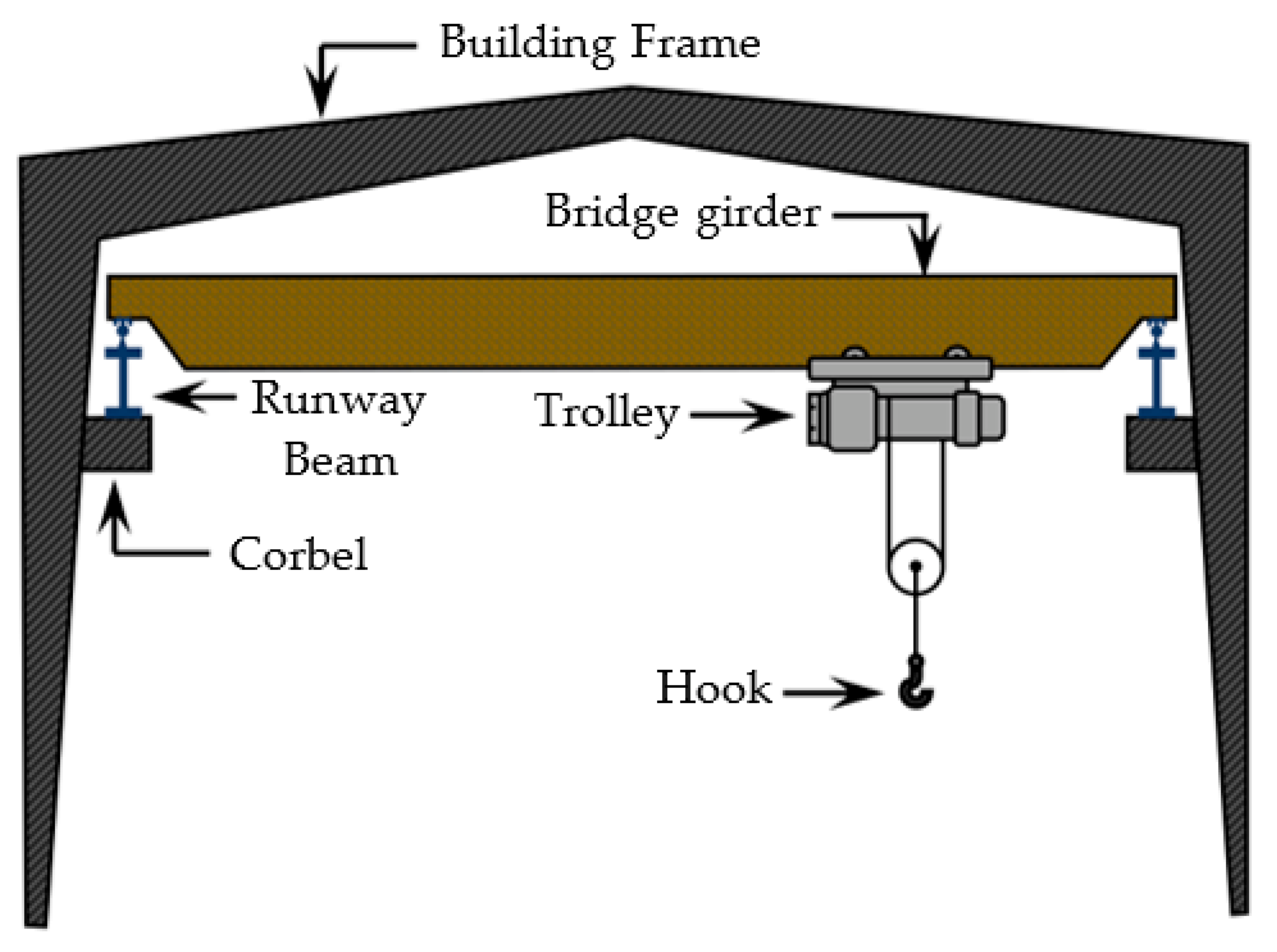
In this section, we describe the design guidelines, in accordance with AISC 360-16 specifications [29], that determine the load carrying capacities of standard RHS and SHS columns under combined axial compression and flexural forces. An RHS/SHS column supports an industrial-purpose crane load from a runway beam sitting on an I-section corbel, which is welded directly to the column face. The geometry of a running crane is depicted in Figure 2. The IBBC model in Figure 3 comprises the SHS column with an I-section corbel beam, where the crane load is applied as a uniformly distributed force over the contact area.
The RHS/SHS column is designed to safely resist the applied crane load, which is determined in accordance with [2,30]. The vertically applied force, transferred at the top flange of an I-section corbel, as shown in Figure 3, is calculated as follows:
W L = R C + H T + 0.5 C W N W b ,
where W L is the maximum wheel load, R C is the rated capacity of the crane, H T is the weight of the hoist with the trolley, C W is the weight of the crane excluding the hoist with the trolley and N W b is the number of end truck wheels at one end of the bridge.
The AISC 360-16 specifications [29] define the capacity of RHS/SHS members under combined compression and flexural forces. Various governing failure modes associated with HSS columns under various applied forces are summarized in [31]. Using this approach, we can classify the design of compression member capacities into non-slender λ λ r and slender λ > λ r sections, where λ is the width-to-thickness ratio of cross-sections b c / t c , λ r = 1.4 E / F y is the associated limit for a non-slender section, E is the modulus of elasticity and F y is yield stress.
The nominal compressive strength for a compression member with a non-slender section P n is expressed as follows:
P n = F c r A g ,
where A g is the gross sectional area. The critical member strength F c r is determined as follows:
when   F y F e 2.25 F c r = F y 0.658 F y F e ,
when   F y F e > 2.25 F c r = 0.877 F e ,
The elastic buckling stress F e is calculated as follows:
F e = π 2 E L c / r 2 ,  
where L c is the effective member length and r is the radius of gyration.
Moreover, the nominal compressive strength of a slender-section compression member is calculated as:
P n = F c r A e ,
where A e is an effective cross-sectional area based on a decreasing effective width, b e 1 . The effective width b e 1 is determined as follows:
when   λ λ r F y F c r b e 1 = b c ,
when   λ > λ r F y F c r b e 1 = b c 1 F e l F c r F e l F c r ,
F e l is an elastic local buckling stress:
F e l = c 2 λ r λ 2 F y ,
c 1 is an effective width-imperfection adjustment factor (i.e., equal to 0.2) and c 2 is equal to 1.38 for RHS/SHS members.
The AISC 360-16 specifications [29] classify the design of flexural members into three categories, namely, compact λ λ p , non-compact λ p < λ λ r and slender λ λ r sections, where λ defines the slenderness ratio of either the flange λ f or the web λ w . For flanges, λ p f = 1.12 E / F y and λ r f = 1.40 E / F y . For webs, λ p w = 2.42 E / F y and λ r w = 5.70 E / F y .
The nominal flexural strength M n is the minimum value calculated in Equations (9)–(12), describing the sectional yielding (plastic moment M p ) and flange/web local buckling failures, as follows:
For a compact section (called yielding):
M n = M p = F y Z ,
For a section with non-compact flanges (local flange buckling):
M n = M p M p F y S 3.57 b c t c F y E 4.0 ,
For a section with non-compact webs (local web buckling):
M n = M p M p F y S 0.305 h t c F y E 0.738 ,
For a section with slender flanges:
M n = F y S e ,
where Z is plastic section modulus about the critical bending axis, S is the elastic section modulus and S e is the effective section modulus, determined based on the effective width. The effective width for a slender flexural element b e 2 is given by:
b e 2 = 1.92 t c E F y 1 0.38 b c / t c E F y b c ,
where h is the depth of the web and t c is the thickness of the column.
The member capacity under the combined compression and flexure forces of a doubly symmetric section is [29]:
w h e n   P r P c 0.2 P r P c + 8 9 M r x M c x + M r y M c y 1.0 ,
w h e n   P r P c < 0.2 P r 2 P c + M r x M c x + M r y M c y 1.0 ,
where P r is the required axial compression force; M r x and M r y are the required flexural forces about the x- and y-axes (e.g., P r × l a in Figure 2), respectively; and l a is the center-to-center distance between the distributed load P L M and the column. Moreover, P c , M c x and M c y are the associated design axial P n and flexural (about the x- and y-axes) M n x and M n y load capacities, respectively.

3. Retrofitting Design of RHS and SHS Columns Using External Plate Stiffeners

3.1. Uniform U-Shaped External Stiffeners

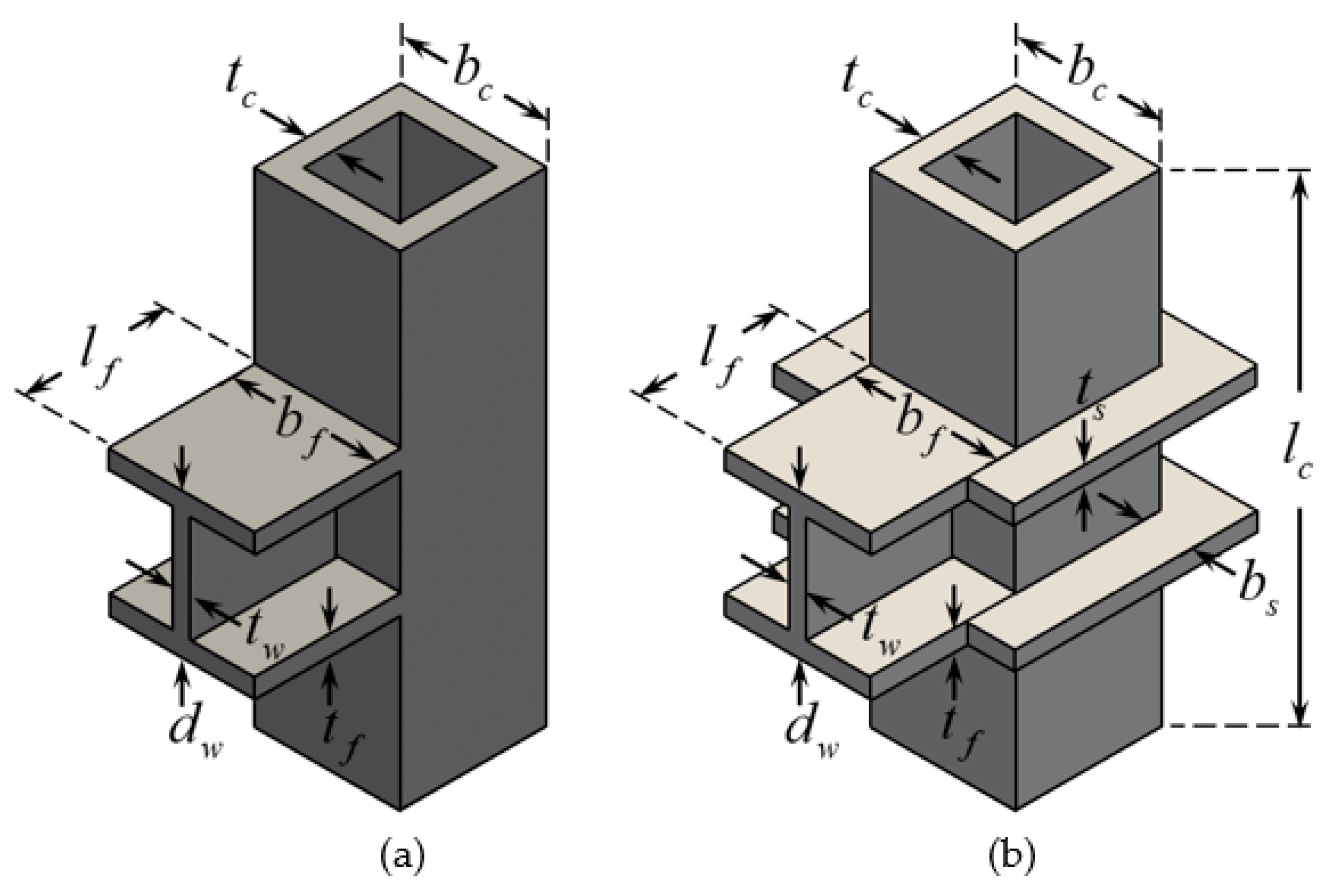
A standard technique adopted to strengthen RHS and SHS columns, depicted in Figure 4a (i.e., to prevent the premature failures involving chord deformations), is the design of external stiffeners enclosed over an IBBC area [6,8]. For instance, as shown in Figure 4b, two U-shaped external steel plates can be welded to the column faces, where the top and bottom flanges of an I-section corbel are connected. The connection between an I-section beam and a circular-hollow-section column with external stiffeners is detailed in [32].
The parameters describing the geometry of a typical HSS column with and without retrofitting plates are defined as follows: b c is the column width; b f and d w are the flange width and web depth of an I-beam, respectively; t c is the column thickness; t f and t w are the thickness of the flange and web, respectively; t s is the thickness of the external stiffener plates; l f is the beam length; and l c is the column length.
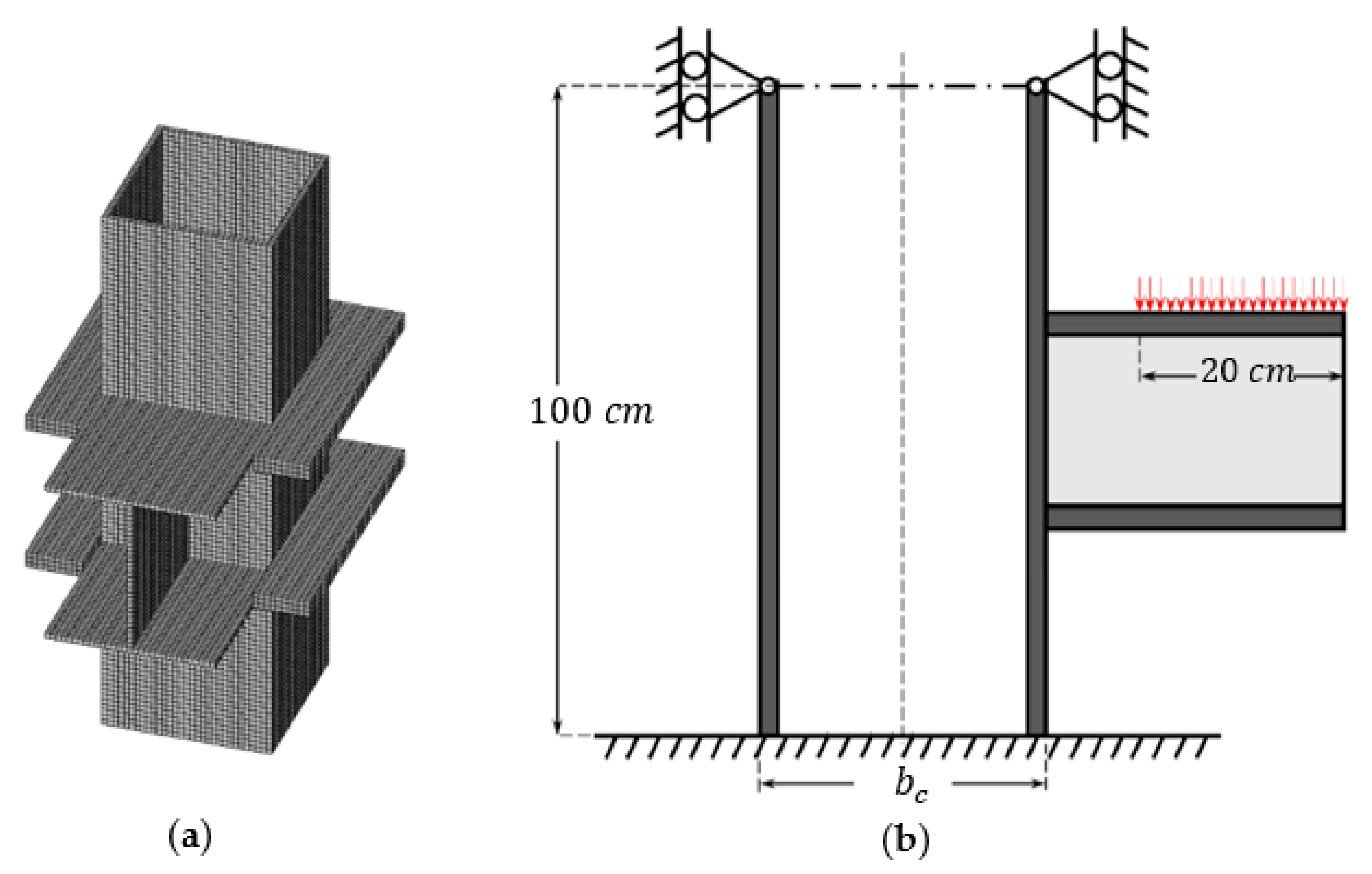
In this study, the responses of SHS columns pre- and post-retrofitting (using U-shaped stiffeners) were mapped out through the implementation of nonlinear 3D FE analyses. Three different SHS columns, having the dimensions b c × t c of SHS—300 × 10, 300 × 5 and 300 × 3—were considered as shown in Figure 5. The I-section corbel with the dimensions b f × d w × t f × t w of H—300 × 300 × 10 × 10—was similarly connected to the columns, where the lengths of l c = 1000   mm and l f = 300   mm were defined to sufficiently describe the local buckling failures of the columns in an IBBC zone. The dimensions of the external U-shaped stiffening plates consisted of a typical width of b s = 100 mm and plate thicknesses ranging from t s = 3   up   to   30   mm .
The material properties of the steel employed in this study were an elastic modulus of 200,000 MPa, Poisson’s ratio of 0.3 and a yield stress of 235 MPa (for the HSS column) and 250 MPa (for the stiffening plates).
The HSS column (with and without stiffeners) and the I-beam in an IBBC area were discretized according to the FE model as shown in Figure 5, comprising eight-node solid elements (called SOLID185) running within the commercial ANSYS Parametric Design Language (APDL) software environment. The model contained a series of uniform FE meshes having a typical size and a minimum thickness among all three structural (HSS column, I-beam and stiffener plate) components. The column was restrained at both ends in all directions, except for a vertical deformation (z-axis) at the top end.
The FE analyses realistically incorporated the influences of inelastic (elastic-perfectly plastic) materials and large (nonlinear geometry) deformations. The responses of the HSS column at an IBBC area under a uniformly applied crane load over a contact surface of 20 cm on an I-beam (see Figure 5b) were analyzed and mapped out.

3.2. External Stiffeners Designed via Topology Optimization

The standard U-shaped external stiffeners, while providing a simple retrofitting solution for SHS/RHS columns, do not efficiently work throughout the entire area of the materials. In essence, a better (more economical yet sufficiently strong) design considers the removal of some ineffective stiffener areas, where the low intensity of stresses is developed under applied load regimes. This, in essence, forms the focus of this study.
In the TO technique for the design of external stiffeners, the optimal layout is developed on the basis of the ground (U-shaped) design of the external stiffener plates. The compliance function f c is minimized under constraints describing the stiffness formulations of the column and beam, as well as the volume fraction V of the designed steel plates. The governing minimization problem is written as:
Minimization :   f c x , u = 1 2 u T K u
Subject   to :   K u = F
V x = e = 1 N e x e v e = V
where K and u are the global stiffness matrix and the displacement vector at degrees of freedom, respectively; v e is the element volume; V x and V are the total and controlled material volumes, respectively; and N e and x e are the total number of discrete elements and the material design variable, respectively.
Various optimization algorithms have been developed to solve the problem stated in Equations (17)–(19). A conventional “hard-kill” ESO method involves the complete elimination of some inefficient discrete elements in the design domain, but this method often encounters the theoretical difficulties in obtaining the optimal layout [33].
As an alternative approach, certain elements can be subjected to a modulus reduction, resulting in very small values. This method was then applied to an ESO [34,35]. Huang and Xie [28] replaced virtual void elements with soft members having very small Young’s modulus values and referred to this method as “soft-kill” BESO. One of the main features of the BESO algorithm is its simplicity in terms of its mathematical formulations. The optimization process can be described by means of a set of simple equations that can be simply implemented. In terms of efficiency, the algorithm is able to produce high-quality solutions within a relatively short amount of time. This is especially true when the material used in the structure is described in a binary form, meaning that it can only be either solid or void. The use of binary materials makes it easier to analyze and optimize the structure, as the only material properties that need to be considered are the stiffness of the solids.
The technique uses an artificial material interpolation scheme with penalization, which is similar to the solid isotropic material with penalization (SIMP) model, to guide the solution towards the design of near-solid voids [36,37,38]. The elastic modulus of each intermediate material is calculated based on the element density as follows:
E x e = E 0 x e p ,   where   x e = x m i n   or   1 ,
where E 0 is the modulus of elasticity of a solid material and p the penalty exponent. The binary variable x e signifies the presence x e = 1 or absence x e = x m i n of the element, where x m i n is defined artificially by a small value (e.g., 0.001). The Poisson’s ratio is assumed to be unrelated to the design variables, and the stiffness matrix K is assembled using standard finite-element procedures by multiplying elemental stiffness matrices K e 0 with design variables x e p :
K = e = 1 N e x e p K e 0 .
In the current l th design iteration, the target volume V l is predetermined at the beginning of each design stage. The amount of material required can be more or less than the initial trial design volume. The target volume continues to decrease or increase in successive iterations until the desired volume constraint is met. The changes in the volume can be described as follows:
V l = V l 1 1 ± c e r ,
where an evolutionary ratio c e r is used to determine the percentage of material to be added or removed in relation to the previous design iteration. Once the desired material volume V r e q (within some certain tolerance) has been reached, the optimization process only adjusts the topology, while maintaining the total design volume. The sensitivity of the structural compliance associated with the change in the e th element is evaluated using the adjoint function [39]:
f c x e = p x e p 1 1 2 u e T K e 0 u e ,
where u e denotes the displacement vector of each element. The optimization of the structure considers discrete design variables x e , constrained to the two bounds of the materials in the design process, as specified in [40]. To determine the sensitivity of each structural element, the BESO method employs the relative ranking of a sensitivity number associated with an individual element. This ranking identifies the elements having the greatest impact on the overall optimization of the structure, and guides the design process towards the optimal solution:
α e = 1 p f c x e = x e p 1 1 2 u e T K e 0 u e .
To ensure that the optimization process is not influenced by checkerboard patterns or mesh dependency, the sensitivity numbers are smoothed using the filter scheme. This mitigates the potential of these factors to have an undue influence on the optimization process, and allows for more reliable and consistent optimization outcomes:
α e = j = 1 N e w e j α j j = 1 N e w e j ,
where the weighted average sum of all individual compliances α e requires a weight factor w e j . This weight factor is determined by the prescribed filter radius r min and the elemental center-to-center distance Δ e j between elements Ω e and Ω j , as follows:
w e j = max 0 , r min Δ e j .
To improve the convergence of an optimization process, the filtered sensitivity numbers are averaged with those from the previous design iteration. This incorporates the lessons learned from the previous iteration and allows the optimization process to build upon its previous progress, leading to the more efficient optimization:
α e l = α e l + α e l 1 2 .
The BESO algorithm optimizes the structure through the removal and addition of elements within the ground structure domain. This process uses two discrete values, namely, x min for void elements and 1 for solid elements. The elemental sensitivity numbers for solid and void materials are represented as follows:
α e = 1 2 u e T K e 0 u e when   x e = 1 x e p 1 1 2 u e T K e 0 u e     when   x e = x min .
Clearly, the sensitivity numbers of solid elements are independent of the penalty exponent p , whereas the sensitivity numbers of soft elements are influenced by p . This means that the optimization process takes into account the relative stiffness of elements and how they contribute to the overall stability and strength of the structure.
The BESO approach has been recently developed to provide the optimal topologies for a wide range of engineering applications, incorporating multi-materials [41,42], additional displacement constraints [43], stiffness and frequency optimization [44,45], nonlinear materials and large deformation [46,47,48] and uncertainties in load directions [49,50]. In this study, we have developed the BESO algorithm for the determination of the optimal layout of two external plate stiffeners welded directly onto the SHS/RHS column faces at the top and bottom flange locations of an I-section beam. The initial ground structure specifically employs simple double U-shaped plates, as depicted in Figure 4b.
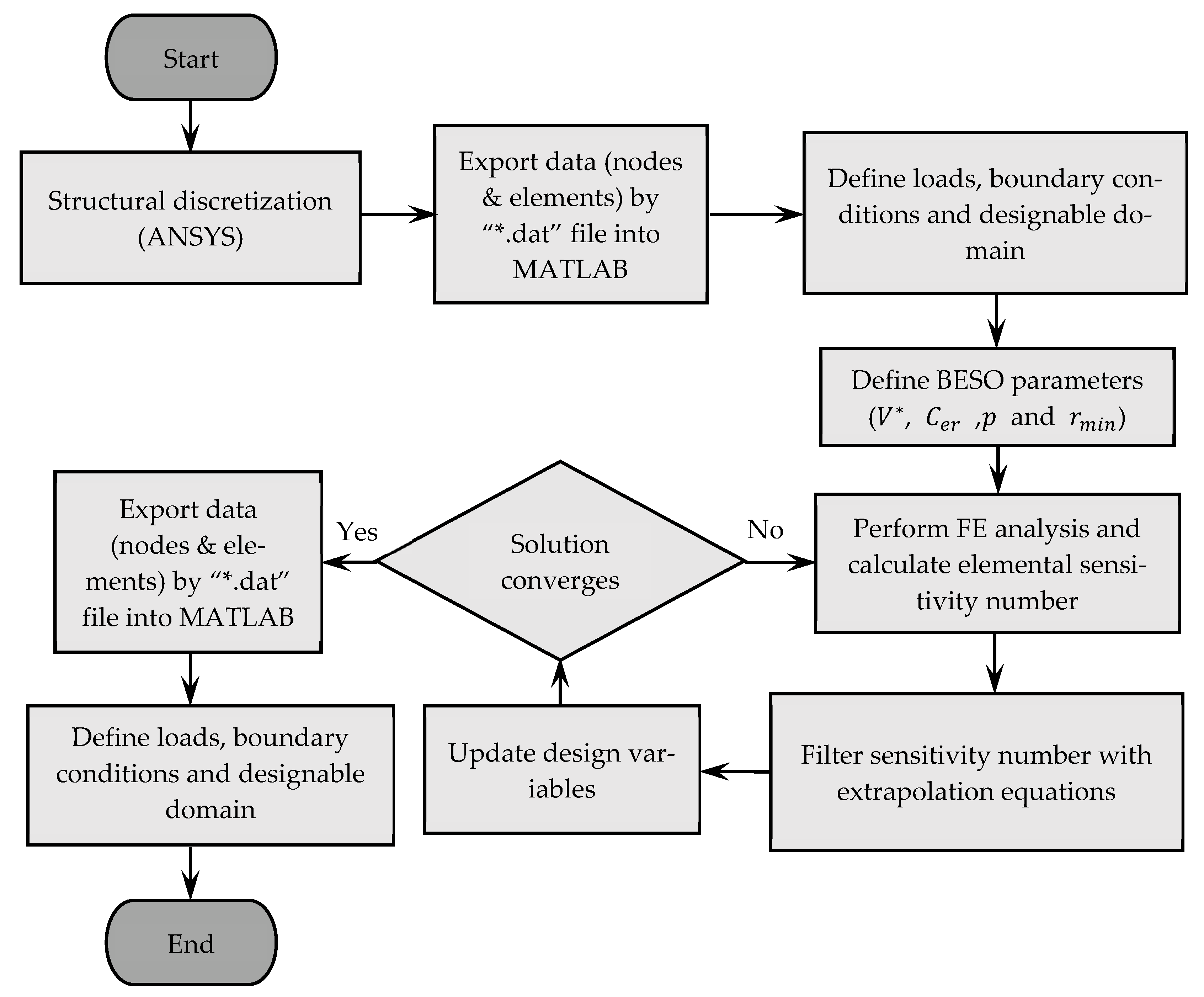
The BESO-based pseudocode for the optimal-topology design of two external steel stiffeners is summarized in the flowchart in Figure 6 and can be described as follows.
Step 
1: Construct the discrete model (i.e., eight-node SOLID185 FEs consisting of the uniform dimensions of 10, 5 and 3 mm associated with the different employed SHS column thicknesses) of the design structure, as shown in Figure 5a. The thickness ( t s = 30   mm ) of two initial U-shaped stiffener plates is preset.
Step 
2: Assign the initial BESO parameters, including the objective volume V , the evolutionary ratio c e r = 5 % , the radius of the filter r min = 3 times the element size and the penalty exponent p = 3 .
Step 
3: Perform the FE analyses. The BESO schemes are used to design only the topologies of two stiffening plates, whereas the models of the SHS/RHS column and I-beam are suited to their individual geometry.
Step 
4: The target volume of the next design iteration is determined. When the current volume V l exceeds the prescribed objective volume V , the target volume for the next design can be calculated using Equation (22).
Step 
5: In Equation (25), the elemental sensitivity numbers of the design variables are evaluated. The sensitivity numbers in the whole design domain are filtered by means of Equations (26)–(28).
Step 
6: The elimination and addition processes are carried out by switching the elemental density. If α e α th , the elemental density of a solid element is changed from 1 to x min , representing the elimination of a member. If α e > α th , the elemental density of a void element is changed from x min to 1, representing the addition of a member. The threshold α th is a lower limit for the sensitivity number, based on the target material volume V l + 1 and the relative ranking of the sensitivity numbers in [28].
Step 
7: Steps 3 to 6 are repeated. The algorithm is terminated when the optimal topology of the steel stiffening plates is achieved. The optimal design is obtained, and no further improvement is made. This is referred to as the solution convergence.
It is worthwhile to note that in this study we considered various volume fraction parameters (ranging from V = 0.5 down to 0.05) associated with the optimal-topology designs. This enabled us to directly define the percentage of the controlled design volume that remained from the initial ground structure, viz., V = 0.5 , indicating that the optimal topology contained 50% of the volume of the original U-shaped plate domain.
The designed external steel plates with the optimal layout were assigned to the SHS/RHS column and the I-beam model such that the elastoplastic analyses of the design structure could be carried out in full using ANSYS software to validate the structure’s strength capacity under applied crane loads. The BESO algorithm was encoded within the MATLAB environment. The application interface between these two environments was accessible through files of the format “*.dat”, thus enabling the transparent data transfers in the collection of structural geometry data and analysis responses.
We assumed that the connections between the two stiffening plates, the I-section corbel and the SHS column were full fillet welds (full rigidity), where the premature failures at the weld sections were not established prior to those of the inelastic SHS column. For the sake of simplicity, none of the interface (debonding) model was considered at an IBBC zone. The von Mises constitutive model with a nonlinear geometry was adopted to describe the inelastic (elastic-plastic) ductile steel materials and hence to capture inelastic local buckling failures. Although under proportional load regimes the failures associated with initial imperfections are not considered, the influences of these can be taken into account, for example, in [51,52], for structures under cyclic/seismic loadings.

4. Results and Discussions

4.1. Responses of SHS Columns without Stiffeners

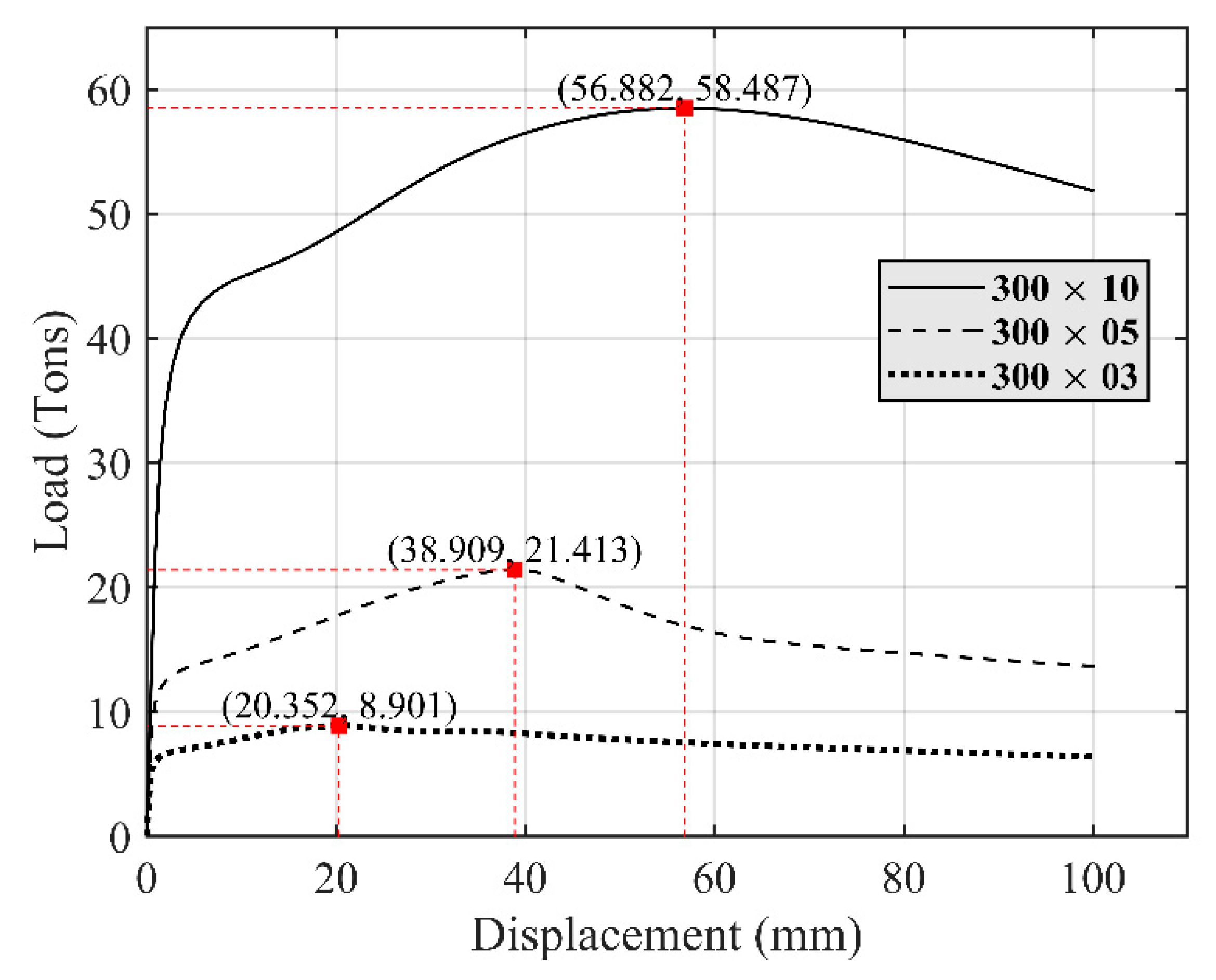
Nonlinear FE analyses were performed to trace the complete load and displacement responses of three SHS column sizes (i.e., SHS-300 × 10, 300 × 5 and 300 × 3). The inelastic responses captured loads and associated displacements (positive in a downward direction) at the end of an I-section corbel, as shown in Figure 7. The constitutive model employed was a ductile (von Mises) material. As expected, increasing the column thickness enhanced the maximum load capacity of the column.
The total maximum loads P N L (tons) applied to an I-beam, such that the SHS column in an IBBC area could sufficiently resist, were captured and these are listed in Table 1. Moreover, the AISC360-16 specifications [29] determined the maximum crane load P L M (tons) applied to an I-beam complying with the nominal ultimate strength capacity, defined by Equations (15) and (16), of the unstiffened SHS columns under combined axial compression and flexural forces, transferred from an I-section corbel. The results of these calculations are also summarized in Table 1.
The maximum crane loads P L M complying with the failures of SHS columns described by the AISC360-16 specifications [29] were (some 15% to 20%) greater than those P N L given by the elastoplastic FE analyses. This illustrated the premature failures resulting the high von Mises stresses that developed at the interfaces between the column face and the I-beam; see Figure 8. For a similar column width, the thinner section limited the stress distribution from the interface into the column area, and vice versa the developed von Mises stress reached the yield limit over a wider sectional area of the thicker columns.

4.2. Responses of SHS Columns with Uniform U-Shaped External Stiffeners

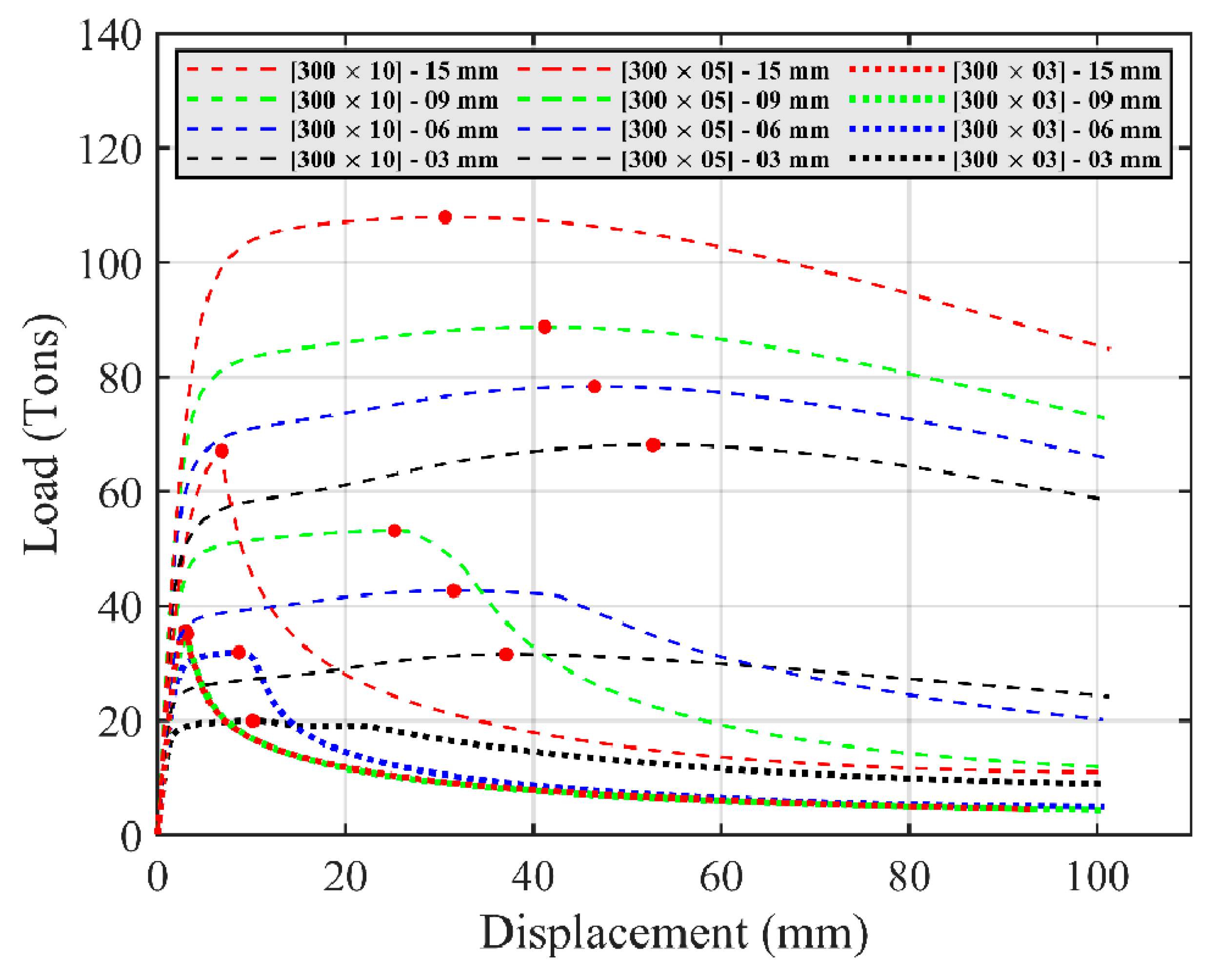
The responses of three SHS columns with uniform U-shaped external stiffeners were mapped through a series of inelastic FE analyses. Various stiffener thicknesses, ranging from t s = 3   to   30   mm , were considered. The associated post-retrofitted maximum load capacities ( P N L ) of the columns applied at an I-beam are reported in Table 2. The load and displacement responses at the corbel for t s = 3 ,   6 ,   9   and   15   mm are plotted in Figure 9. As expected, an increase in the thickness of the external stiffeners enhanced the maximum load capacity of the column at an IBBC area (by up to two times for t s = 30   mm ).
For the two SHS-300 × 03 and 300 × 5 columns which had slender sections, an increase in the stiffener thickness decreased the column’s ductility. This was at variance with the non-slender SHS-300 × 10 column, of which the ductility was maintained at the higher load capacity. Moreover, the small-section columns did not exhibit significant strength improvements with overdesigned stiffeners. For example, a change in stiffener thickness from 9 to 15 mm did not increase the post-retrofitted column capacity.

4.3. Responses of SHS Columns with External Stiffeners Designed via Topology Optimizaiton

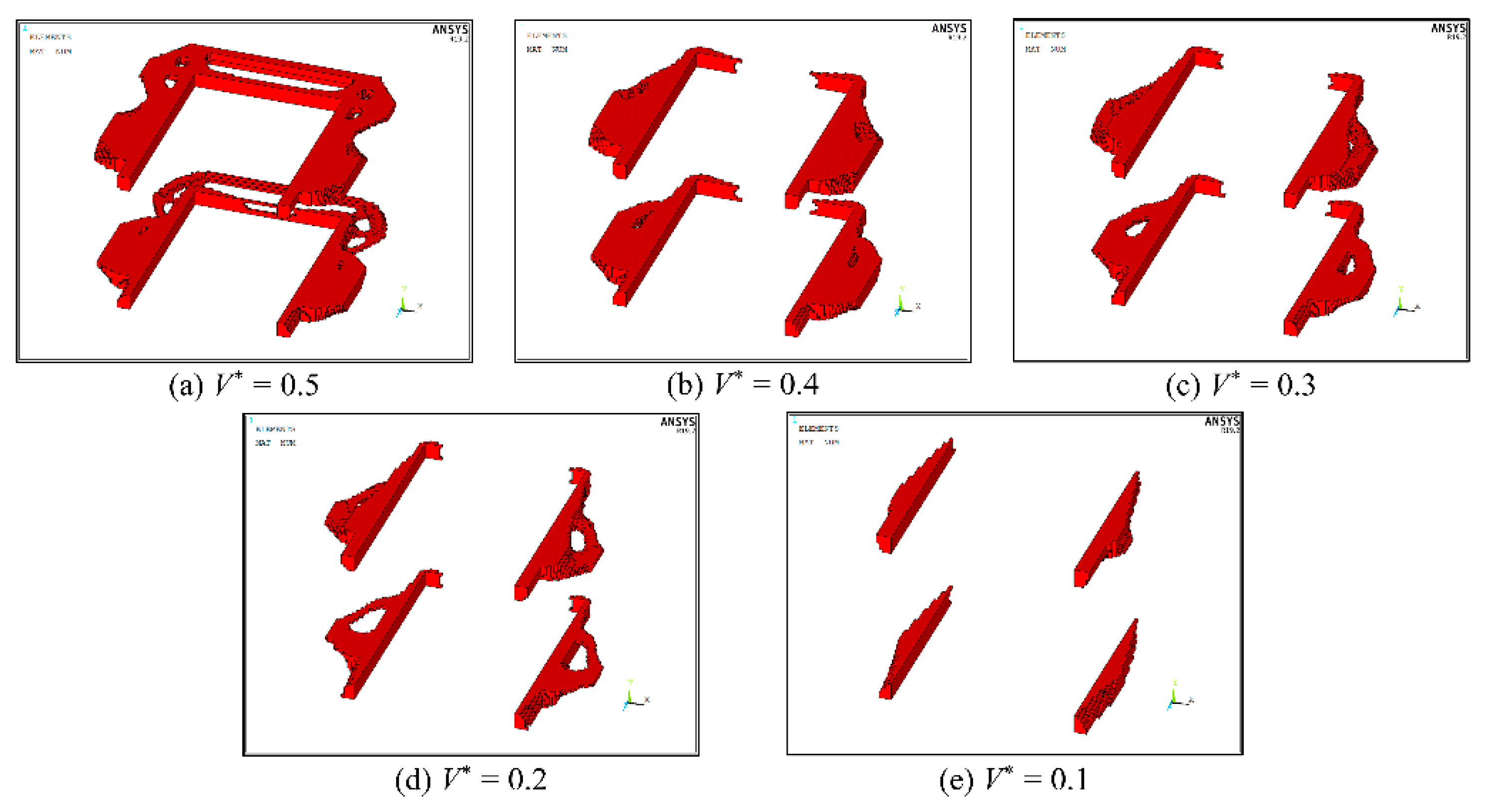
The final design developed using the state-of-the-art BESO method [46] to determine the optimal topology of non-uniform steel stiffener plates is plotted in Figure 10. The design process was implemented for different volume fractions ranging from V = 0.5   down   to   0.05 , defining the fractions of the remaining design volume based on that of the initial ground structure (viz., in this case, two uniform U-shaped plates with t s = 30   mm ).
Clearly, the BESO process removed the inefficient discrete elements of two steel plates, while maintaining only those with active von-Mises stresses that developed under the applied forces. At V = 0.5 , the elements around the four corners of the steel plates were eliminated, with the introduction of voids on the back column’s face. The lower value of V yielded an optimal stiffener layout by maintaining only the discrete elements located close to the contact face with an I-beam in an IBBC area.
The maximum crane loads P N L , such that the SHS columns in an IBBC area could sufficiently carry the loads after retrofitting using the optimal-topology design of the external stiffeners, are summarized in Table 3. The total design volumes associated with the controlled volume fractions are also reported. It was evident that for a similar targeted maximum crane load P N L , the total required volume of the optimal-topology stiffeners was less than that of the standard uniform U-shaped plates for SHS columns. For instance, for the SHS-300 × 05 column to sufficiently support P N L 48   tons , the BESO approach was used to design the optimal layout of stiffeners shown in Figure 9e, with V = 0.1 , for which the total volume of 773 cm3 (viz., yielding P N L = 48.611   tons ) was significantly less than that of the uniform U-shaped plates (namely, 2080 cm3 for P N L = 49.800   tons ).
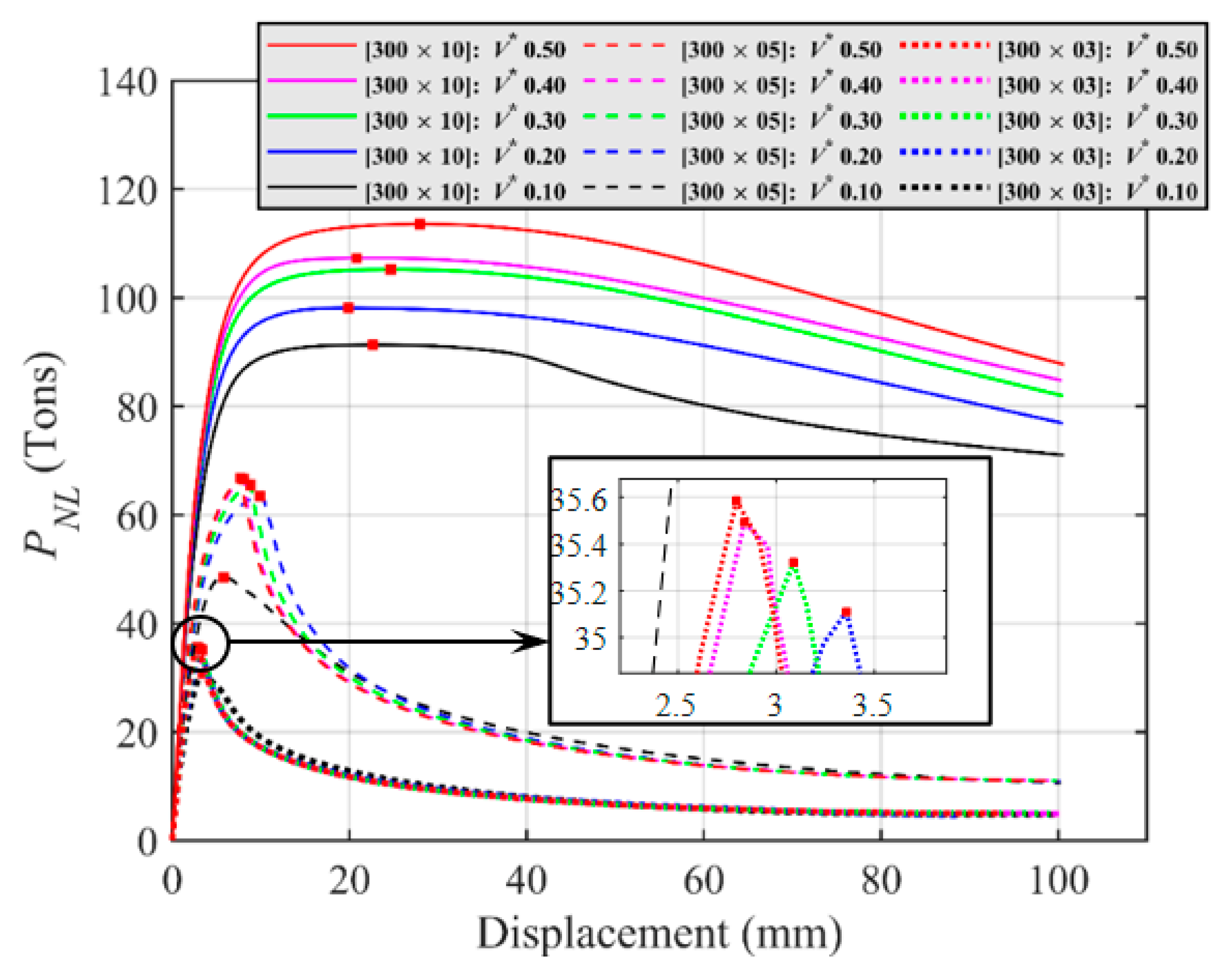
The nonlinear load and displacement responses of the I-section corbel associated with the SHS column in an IBBC area are mapped out in Figure 11 for various optimal-topology designs. It was clear that the optimal-topology stiffeners with higher volume fractions provided greater maximum crane load capacities to the columns. The strength enhancement was apparent in non-slender compression columns (e.g., SHS-300 × 10). The advantages of optimal retrofitting were not as evident when the slender columns (SHS-300 × 03 and SHS-300 × 05) were considered. The slenderer compression members gained less strength enhancements from the retrofitted designs presented here.
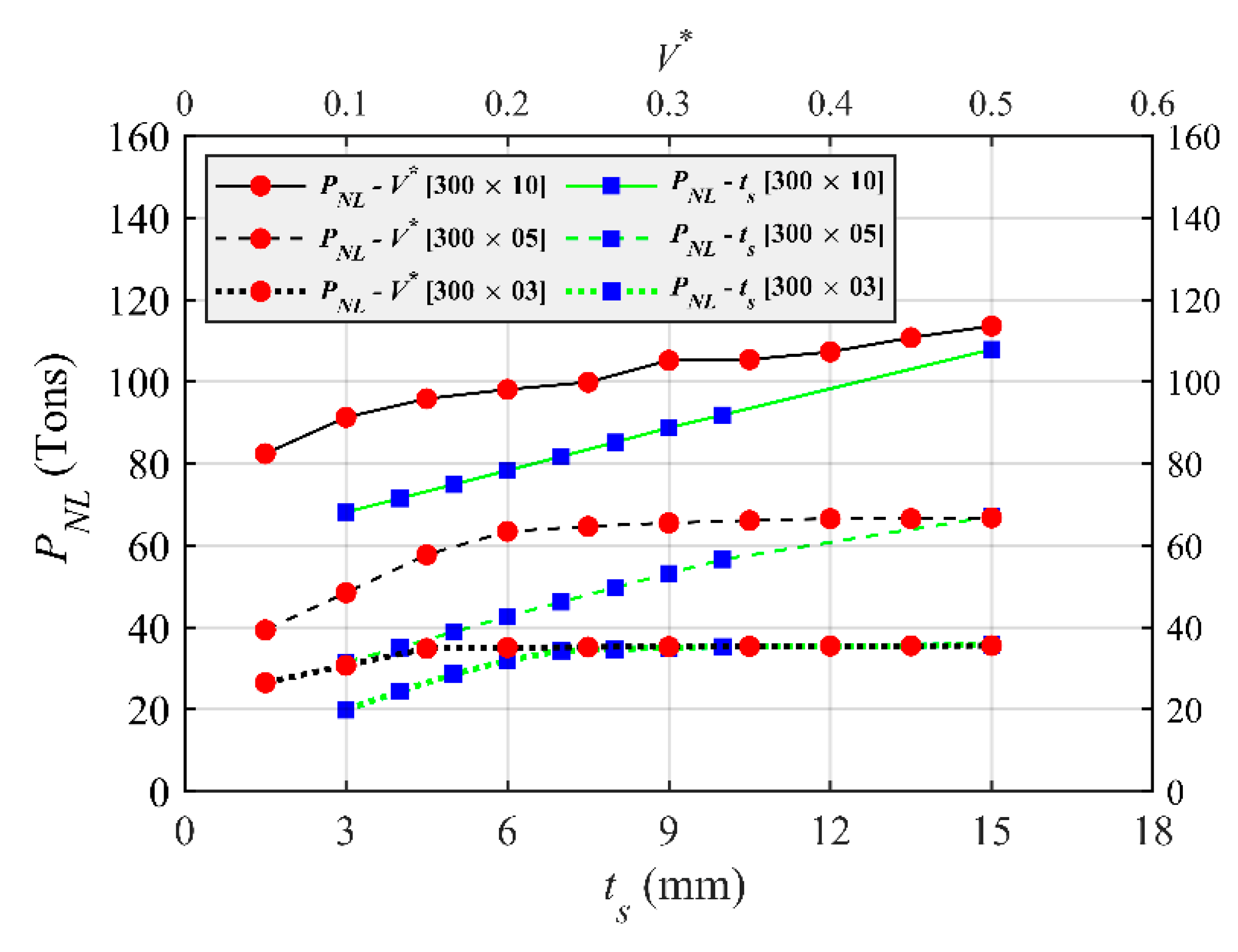
The similar conclusion can be drawn on the basis of the results presented in Figure 12 regarding both the optimal-topology and uniform U-shaped stiffener designs, depicting the relationship between the maximum crane loads P N L and the total design stiffener volumes (which were in direct relation to the plate thickness t s and design volume fraction V ). More specifically, the non-slender SHS-300 × 10 column progressively gained a higher strength capacity with increases in the total volume of the stiffeners. On the contrary, the two non-slender SHS-300 × 03 and SHS-300 × 05 columns were only able to obtain strength enhancements early in the process, when the total plate volumes had not yet reached their individual thresholds. The increase in the volume fractions (or the plate thicknesses of uniform stiffeners) did not clearly provide a higher column load capacity, as the premature failure (local buckling at the interface with the I-beam) was no longer governing the ultimate strength of the column in the IBBC zone. In all cases, the optimal-topology BESO-based design enabled a more effective retrofitting procedure with a more quickly increasing rate of maximum crane loads for the columns, as compared to standard uniform U-shaped external stiffeners.

5. Conclusions

The BESO-based optimal-topology approach has been presented here as a cost-effective retrofitting method for HSS (viz., RHS and SHS) columns supporting industrial crane loads. The technique enabled significant volume reductions for the external steel retrofitting plates (as compared to standard uniform U-shaped external stiffeners) connected to the column at the top and bottom flange locations of an I-section corbel under running cranes. The columns examined here included both non-slender and slender compression members. The nonlinear responses of pre- and post-strengthened columns under various applied forces were mapped as part of a comprehensive FE analyses, incorporating inelastic material and nonlinear geometric properties, simultaneously. The robustness and accuracy of the proposed retrofitted scheme were demonstrated through comparisons with AISC 360-16 specifications in the case of pre-retrofitted column applications and the use of uniform U-shaped double plate stiffeners in the case of post-retrofitted designs. Three pertinent conclusions can therefore be drawn as follows.
  • The premature local buckling failures of column chords connected to an I-section corbel supporting crane forces were captured by the combined elastoplastic and large deformation analyses performed in this study. In this study, we depicted the high von Mises stress intensity as well as the buckling shape of the column in an IBBC area. The nonlinear responses of pre-retrofitted columns showed reductions of 15% to 20% in the maximum crane load capacities as compared to those defined by the AISC 360-16 specifications. The local buckling failures were more pronounced in the slenderer section columns.
  • The standard uniform U-shaped external stiffeners enhanced the strength capacity of the columns. The maximum crane loads increased in proportion to the thickness of the steel plates employed. The use of external plates enabled the columns to overcome premature local buckling failures at an IBBC area and hence more stress distributions developed throughout the column faces. Moreover, the post-retrofitted behaviors of slender section columns only gained a higher strength capacity with the increasing of the thickness of stiffeners up to certain thresholds, at which thicker plates could not provide benefits to the columns’ capacity. These thresholds were more concerning in relatively slender columns.
  • The BESO-based retrofitting method provided the optimal layout of two stiffener plates welded to the column at an IBBC area. The post-retrofitted responses of the column with the optimal-topology stiffeners were mapped out and used to demonstrate the cost-effective design of the (non-slender and slender sectional) columns to overcome premature local buckling failures. For similar crane-load capacity targets, the steel stiffener plates designed via the proposed retrofitting scheme exhibited significantly lower (and thus more economical) total volumes than those required for the uniform U-shaped plates. The strength enhancement was more efficient for non-slender columns. For slender columns, the benefits of external plate stiffeners were limited at some certain thresholds, at which the local buckling failures were no longer pronounced.

Author Contributions

R.S.: data curation, formal analysis, software, validation, writing—original draft preparation; S.T.: conceptualization, investigation, methodology, resources, writing—original draft preparation, supervision, funding acquisition; T.H.V.: visualization. All authors have read and agreed to the published version of the manuscript.

Funding

This Research is funded by Thailand Science research and Innovation Fund Chulalongkorn University (IND66210025). Support from Chulalongkorn University under Ratchadaphiseksomphot Endowment Fund and The Second Century Fund is also acknowledged.

Data Availability Statement

The data presented in this study are available on request from the corresponding author.

Conflicts of Interest

The authors declare no conflict of interest.

References

  1. Kurobane, Y.; Packer, J.A.; Wardenier, J. Design Guide for Structural Hollow Section Column Connections. In CIDECT Series “Construction with Hollow Steel Sections” No. 9; TÜV-Verlag: Köln, Germany, 2004. [Google Scholar]
  2. NBCC. National Building Code of Canada; Associate Committee on the National Building Code, National Research Council: Ottawa, ON, Canada, 2015. [Google Scholar]
  3. Qin, Y.; Chen, Z.; Han, N. Research on design of through-diaphragm connections between CFRT columns and HSS beams. Int. J. Steel Struct. 2014, 14, 589–600. [Google Scholar] [CrossRef]
  4. Bai, Y.; Wang, S.; Mou, B.; Wang, Y.; Skalomenos, K.A. Bi-directional seismic behavior of steel beam-column connections with outer annular stiffener. Eng. Struct. 2021, 227, 111443. [Google Scholar] [CrossRef]
  5. Mou, B.; Liu, Y.; Wei, P.; Zhao, F.; Chenglong, W.; Ning, N. Numerical investigation and design method of bolted beam-column joint panel with eccentricity in beam depths. J. Constr. Steel Res. 2021, 180, 106568. [Google Scholar] [CrossRef]
  6. Ting, L.C.; Shanmugam, N.E.; Lee, S.L. Box-column to I-beam connections with external stiffeners. J. Constr. Steel Res. 1991, 18, 209–226. [Google Scholar] [CrossRef]
  7. Ting, L.C.; Shanmugam, N.E.; Lee, S.L. Use of external T-stiffeners in box-column to I-beam connections. J. Constr. Steel Res. 1993, 26, 77–98. [Google Scholar] [CrossRef]
  8. Lee, M.M.; Llewelyn-Parry, A. Strength of ring-stiffened tubular T-joints in offshore structures. J. Constr. Steel Res. 1999, 51, 239–264. [Google Scholar] [CrossRef]
  9. Hiroshi, M.; Tanaka, A. Statical characteristics of the improved beam-to-column connections of steel structure. In Proceedings of the 12th World Conference on Earthquake Engineering, Auckland, New Zealand, 30 January–4 February 2000. [Google Scholar]
  10. Goswami, R.; Murty, C.V.R. Externally Reinforced Welded I-Beam-to-Box-Column Seismic Connection. J. Eng. Mech. 2010, 136, 23–30. [Google Scholar] [CrossRef]
  11. Vulcu, C.; Stratan, A.; Ciutina, A.; Dubina, D. Beam-to-CFT High-Strength Joints with External Diaphragm. I: Design and Experimental Validation. J. Struct. Eng. 2017, 143, 04017001. [Google Scholar] [CrossRef]
  12. Vulcu, C.; Stratan, A.; Ciutina, A.; Dubina, D. Beam-to-CFT High-Strength Joints with External Diaphragm. II Numerical Simulation of Joint Behavior. J. Struct. Eng. 2017, 143, 04017002. [Google Scholar] [CrossRef]
  13. Michell, A.G.M. LVIII. The limits of economy of material in frame-structures. Lond. Edinb. Dublin Philos. Mag. J. Sci. 1904, 8, 589–597. [Google Scholar] [CrossRef] [Green Version]
  14. Rozvany, G. Grillages of maximum strength and maximum stiffness. Int. J. Mech. Sci. 1972, 14, 651–666. [Google Scholar] [CrossRef]
  15. Rozvany, G. Optimal load transmission by flexure. Comput. Methods Appl. Mech. Eng. 1972, 1, 253–263. [Google Scholar] [CrossRef]
  16. Prager, W.; Rozvany, G. Optimal layout of grillages. J. Struct. Mech. 1977, 5, 1–18. [Google Scholar] [CrossRef]
  17. Xia, L.; Xia, Q.; Huang, X.; Xie, Y.M. Bi-directional Evolutionary Structural Optimization on Advanced Structures and Materials: A Comprehensive Review. Arch. Comput. Methods Eng. 2016, 25, 437–478. [Google Scholar] [CrossRef]
  18. Cheng, K.; Olhoff, N. An investigation concerning optimal design of solid elastic plates. Int. J. Solids Struct. 1981, 17, 305–323. [Google Scholar] [CrossRef]
  19. Kohn, R.; Strang, G. Optimal design and relaxation of variational problems (Part I). Comm. Pure Appl. Math. 1986, 39, 113–137. [Google Scholar] [CrossRef]
  20. Kohn, R.; Strang, G. Optimal design and relaxation of variational problems (Part II). Comm. Pure Appl. Math. 1986, 39, 139–182. [Google Scholar] [CrossRef]
  21. Kohn, R.; Strang, G. Optimal design and relaxation of variational problems (Part III). Comm. Pure Appl. Math. 1986, 39, 353–377. [Google Scholar] [CrossRef]
  22. Bendsøe, M.P.; Kikuchi, N. Generating optimal topologies in structural design using a homogenization method. Comput. Methods Appl. Mech. Eng. 1988, 71, 197–224. [Google Scholar] [CrossRef]
  23. Xie, Y.M.; Steven, G.P. Shape and layout optimization via an evolutionary procedure. In Proceedings of the International Conference on Computational Engineering Science, Hong Kong, China, 17–22 December 1992. [Google Scholar]
  24. Xie, Y.M.; Steven, G.P. A simple evolutionary procedure for structural optimization. Comput. Struct. 1993, 49, 885–896. [Google Scholar] [CrossRef]
  25. Querin, O.M.; Steven, G.P.; Xie, Y.M. Evolutionary structural optimisation (ESO) using a bidirectional algorithm. Eng. Comput. 1998, 15, 1031–1048. [Google Scholar] [CrossRef]
  26. Querin, O.M.; Steven, G.P.; Xie, Y.M. Evolutionary structural optimization using an additive algorithm. Finite Elem. Anal. Des. 2000, 34, 291–308. [Google Scholar] [CrossRef]
  27. Querin, O.M.; Young, V.; Steven, G.P.; Xie, Y.M. Computational efficiency and validation of bi-directional evolutionary structural optimisation. Comput. Methods Appl. Mech. Eng. 2000, 189, 559–573. [Google Scholar] [CrossRef]
  28. Huang, X.; Xie, Y.M. Convergent and mesh-independent solutions for the bi-directional evolutionary structural optimization method. Finite Elem. Anal. Des. 2007, 43, 1039–1049. [Google Scholar] [CrossRef]
  29. ANSI/AISC 360-16; Specification for Structural Steel Buildings. American Institute of Steel Construction: Chicago, IL, USA, 2016.
  30. MBMA. Metal Building Systems Manual; Metal Building Manufacturers Association: Cleveland, OH, USA, 2012. [Google Scholar]
  31. Wardenier, J. Hollow Sections in Structural Applications, 2nd ed.; Delft University: Delft, The Netherlands, 2010. [Google Scholar]
  32. Bagheri Sabbagh, A.; Chan, T.M.; Mottram, J.T. Detailing of I-beam-to-CHS column joints with external diaphragm plates for seismic actions. J. Constr. Steel Res. 2013, 88, 21–33. [Google Scholar] [CrossRef]
  33. Zhou, M.; Rozvany, G. On the validity of ESO type methods in topology optimization. Struct. Multidiscip. Optim. 2001, 21, 80–83. [Google Scholar] [CrossRef]
  34. Hinton, E.; Sienz, J. Fully stressed topological design of structures using an evolutionary procedure. Eng. Comput. 1995, 12, 229–244. [Google Scholar] [CrossRef]
  35. Rozvany, G.; Querin, O.M. Combining ESO with rigorous optimality criteria. Int. J. Veh. Des. 2002, 28, 294. [Google Scholar] [CrossRef]
  36. Bendsøe, M.P. Optimal shape design as a material distribution problem. Struct. Optimiz. 1989, 1, 193–202. [Google Scholar] [CrossRef]
  37. Bendsøe, M.P.; Sigmund, O. Material interpolation schemes in topology optimization. Arch. Appl. Mech. 1999, 69, 635–654. [Google Scholar] [CrossRef]
  38. Rietz, A. Sufficiency of a finite exponent in SIMP (power law) methods. Struct. Multidiscip. Optim. 2001, 21, 159–163. [Google Scholar] [CrossRef]
  39. Bendsøe, M.P.; Sigmund, O. Topology Optimization: Theory, Methods and Applications; Springer: Berlin/Heidelberg, Germany, 2003. [Google Scholar]
  40. Xia, L.; Breitkopf, P. Recent Advances on Topology Optimization of Multiscale Nonlinear Structures. Arch. Comput. Methods Eng. 2017, 24, 227–249. [Google Scholar] [CrossRef]
  41. Huang, X.; Xie, Y.M. Bi-directional evolutionary topology optimization of continuum structures with one or multiple materials. Comput. Mech. 2009, 43, 393–401. [Google Scholar] [CrossRef]
  42. Gan, N.; Wang, Q. Topology optimization of multiphase materials with dynamic and static characteristics by BESO method. Adv. Eng. Softw. 2021, 151, 102928. [Google Scholar] [CrossRef]
  43. Huang, X.; Xie, Y.M. Evolutionary topology optimization of continuum structures with an additional displacement constraint. Struct. Multidiscip. Optim. 2010, 40, 409–416. [Google Scholar] [CrossRef]
  44. Huang, X.; Zuo, Z.H.; Xie, Y.M. Evolutionary topological optimization of vibrating continuum structures for natural frequencies. Comput. Struct. 2010, 88, 357–364. [Google Scholar] [CrossRef]
  45. Teimouri, M.; Asgari, M. Multi-objective BESO topology optimization for stiffness and frequency of continuum structures. Struct. Eng. Mech. 2019, 72, 181–190. [Google Scholar] [CrossRef]
  46. Huang, X.H.; Xie, Y.M. Bidirectional Evolutionary Topology Optimization for Structures with Geometrical and Material Nonlinearities. AIAA J. 2007, 45, 308–313. [Google Scholar] [CrossRef]
  47. Han, Y.; Xu, B.; Liu, Y. An efficient 137-line MATLAB code for geometrically nonlinear topology optimization using bi-directional evolutionary structural optimization method. Struct. Multidisc. Optim. 2021, 63, 2571–2588. [Google Scholar] [CrossRef]
  48. Xu, B.; Han, Y.; Zhao, L. Bi-directional evolutionary stress-based topology optimization of material nonlinear structures. Struct. Multidisc. Optim. 2021, 63, 1287–1305. [Google Scholar] [CrossRef]
  49. Liu, J.; Wen, G.; Qing, Q.; Xie, Y.M. An efficient method for topology optimization of continuum structures in the presence of uncertainty in loading direction. Int. J. Comput. Methods 2017, 14, 1750054. [Google Scholar] [CrossRef]
  50. Rostami, S.A.L.; Kolahdooz, A.; Zhang, J. Robust topology optimization under material and loading uncertainties using an evolutionary structural extended finite element method. Eng. Anal. Bound. Elem. 2021, 133, 61–70. [Google Scholar] [CrossRef]
  51. El-Sisi, A.A.; Elgiar, M.M.; Maaly, H.M.; Shallan, O.A.; Salim, H.A. Effect of Welding Separation Characteristics on the Cyclic Behavior of Steel Plate Shear Walls. Buildings. 2022, 12, 879. [Google Scholar] [CrossRef]
  52. Shallan, O.A.; Maaly, H.M.; Elgiar, M.M.; El-Sisi, A.A. Effect of Stiffener Characteristics on the Seismic Behavior and Fracture Tendency of Steel Shear Walls. Frat. Integrita Strutt. 2020, 14, 104–115. [Google Scholar] [CrossRef]
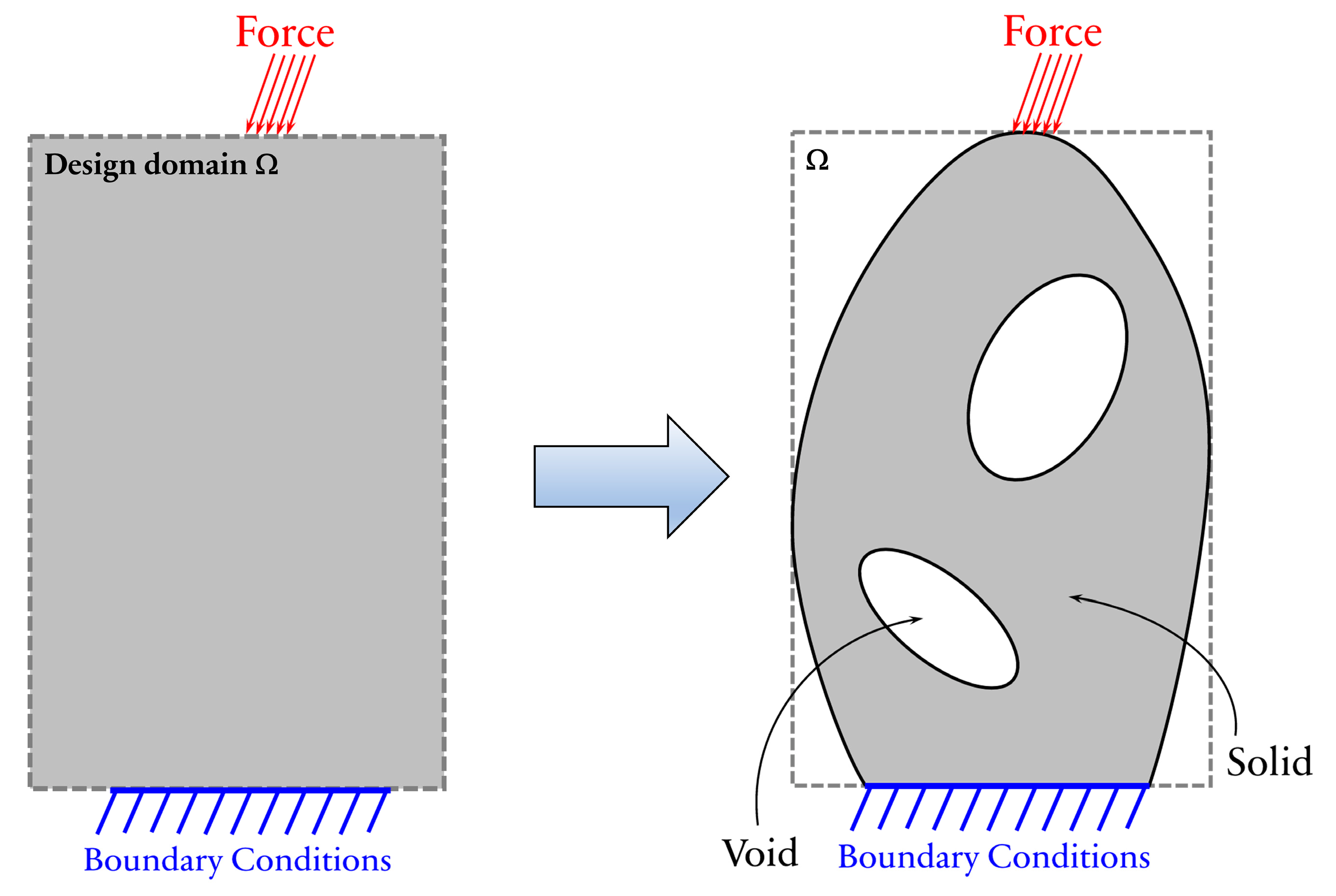
Figure 1. Typical topology/structural optimization under applied load and boundary conditions.
Buildings 13 00328 g001
Figure 2. Typical details of a top running bridge crane with a suspended trolley.
Buildings 13 00328 g002
Figure 3. IBBC model with transferred crane load.
Buildings 13 00328 g003
Figure 4. HSS column in an IBBC area—(a) pre-retrofitting, (b) post-retrofitting.
Buildings 13 00328 g004
Figure 5. IBBC model between HSS columns and I-beams. (a) FE model, (b) boundary conditions.
Buildings 13 00328 g005
Figure 6. Topology optimization framework for optimal stiffener plate designs.
Buildings 13 00328 g006
Figure 7. Load and displacement responses of unstiffened columns.
Buildings 13 00328 g007
Figure 8. Von-Mises stress distribution at maximum load capacity.
Buildings 13 00328 g008
Figure 9. Load-displacement responses of SHS columns with uniform external stiffeners.
Buildings 13 00328 g009
Figure 10. Optimal stiffener topology for SHS-300 × 0.5 columns with various volume fractions.
Buildings 13 00328 g010
Figure 11. Load-displacement responses of SHS columns with optimal-topology stiffeners.
Buildings 13 00328 g011
Figure 12. Maximum crane load capacities of SHS columns with uniform and optimal-topology stiffeners.
Buildings 13 00328 g012
Table 1. Maximum crane loads of unstiffened SHS columns.
SHS
Column
Slenderness of Compression MemberSlenderness of Flexural Member P L M
(Tons)
P N L
(Tons)
FlangeWeb
300 × 03SlenderSlenderNon-compact10.7088.901
300 × 05SlenderSlenderCompact27.17221.413
300 × 10Non-slenderCompactCompact67.84458.487
Table 2. Maximum crane loads of SHS columns with uniform external stiffeners.
t s (mm) Volume (cm3) P N L (Tons)
SHS 300 × 03SHS 300 × 05SHS 300 × 10
378020.07231.64968.146
4104024.56535.21471.508
5130028.69339.01874.907
6156031.97942.75678.319
7182034.66846.32281.479
8208035.05849.80085.220
9234035.17253.25588.753
10260035.54156.65891.888
15390035.68167.032107.890
30780036.00167.830126.690
Table 3. Maximum crane loads of SHS columns with optimal-topology stiffeners.
V SHS-300 × 03SHS-300 × 05SHS-300 × 10
Volume (cm3) P N L (Tons) Volume (cm3) P N L (Tons) Volume (cm3) P N L (Tons)
0.0539026.59738339.47738282.450
0.1078030.86477348.61177291.305
0.15117035.109116357.950116295.858
0.20156035.278155463.609155298.126
0.25195035.655194464.912193299.872
0.30234035.718233565.7872336105.220
0.35273035.728272566.7412726105.420
0.40312035.801311666.9123116107.290
0.45351035.809350666.9383504110.760
0.50390035.835389667.0453896113.600
Disclaimer/Publisher’s Note: The statements, opinions and data contained in all publications are solely those of the individual author(s) and contributor(s) and not of MDPI and/or the editor(s). MDPI and/or the editor(s) disclaim responsibility for any injury to people or property resulting from any ideas, methods, instructions or products referred to in the content.