Abstract
Recently, there has been an increasing number of studies on the distortional buckling analyses of cold-formed steel (CFS) channels with web edge-stiffened holes. However, the literature about the analytical solutions is scarce, and the current design rules, e.g., the American Iron and Steel Institute (AISI 2016) and the Australian/New Zealand standards (AS/NZ 4600: 2018), provide little design advice for CFS channels with edge-stiffened holes. This paper presents an analytical method for estimating the bearing capacity for the distortional buckling of CFS channel beams with edge-stiffened rectangular web holes. To validate the proposed method, comprehensive finite element (FE) analyses were performed. The proposed design equations accurately forecast the distortional buckling moment capacities of the CFS channels with edge-stiffened holes. Specifically, the average error of the critical moment predictions for the distortional buckling of perforated CFS channel beams obtained by the proposed analytical method and the finite element method (FEM) is only 6.59%, where the maximum error reaches 17.76%. Moreover, a parameter study on the effect of the edge-stiffener length on the bearing capacity was carried out as well, and the results show that the edge stiffener indeed significantly enhanced the critical moment when it is below a threshold length, but the enhancement becomes unobvious once surpassing the threshold length.
1. Introduction
Cold-formed steel sections are more and more widely used in the fields of building construction, automobile, aerospace, and other fields because of their high degree of industrialization, high construction quality, short construction cycle, long service life, admirable colligated economy, energy savings, environmental protection, and other excellent characteristics. To ensure the laying of water pipes, electric wires, and heating pipes as well as better economy, the practical application of cold-formed steel often requires precutting holes on the webs of beams. As a result, this will cause changes in the elastic buckling (especially the performance of the distortional buckling mode) and stability of the component. To compensate for the lack of mechanical properties of the member, the edge of the hole can be stiffened. Recently, more and more scholars are paying attention to studying such components with edge-stiffened holes. Nevertheless, there is less analytical research on the critical moment of the distortional buckling mode. In addition, there is almost no introduction to the relevant content in the current design, such as the American Iron and Steel Institute (AISI) [1], EN1993-1-3 [2] and the Australian and New Zealand Standards (AS/NZS) [3].
In the extensive research works concerning the distortional buckling of CFS channel members without web holes, Law and Hancock [4,5] first derived the distortional buckling formulas for channel columns and beams with no holes, which has been adopted by the AISI, and their analytical model has a continuous reference significance. Li and Chen [6] provided the other analytical model for analyzing the distortional buckling of cold-formed steel sections. Schafer et al. [7,8] clarified the features of the distortional buckling mode and provided a design method for cold-formed steel members. Liu et al. [9,10] analyzed distortional buckling formulas for different boundary conditions with CFS columns with no holes. In addition, other authors, such as Nan-ting Yu, Daniel, and others [11,12,13,14,15], provided an energy-based approach to obtain explicit equations for the distortional buckling of cold-formed steel sections without holes or with unstiffened holes. Concerning CFS channel members with unstiffened web holes, Schafer and Moen et al. [16,17,18,19,20,21,22] conducted plenty of experimental, analytical, and numerical studies on the elastic buckling of CFS components with unstiffened holes and provided effective design methods for calculating the strength of CFS beams with unstiffened web holes, which have been adopted by the AISI and AS/NZS. The aforementioned studies on CFS components with no holes or unstiffened web holes enable us to evaluate or calculate the distortional buckling behavior of components or provide a basis for the establishment of design methods.
However, only a small number of studies focused on the elastic buckling of CFS channel members with edge-stiffened web openings. Chen et al. [23,24] conducted a series of experimental and numerical studies on the axial strength and moment capacity for the cold-formed steel channel sections undergoing compression and bending. Their study shows that the edge-stiffened web holes can enhance the moment capacity of CFS channel beams, compared to those with unstiffened web holes or plain channels. Furthermore, Chen et al. [25] experimentally and numerically studied the axial strength of back-to-back cold-formed steel channels with edge-stiffened holes on the webs, and they also compared the results with those of members with unstiffened holes and unperforated webs, they further provided simplified design equations for cold-formed steel channels with edge-stiffened holes under axial compression, even if the equations were not analytical. In addition, the research team of Chen [26] researched the shear capacity of cold-formed steel channels with edge-stiffened web holes on an experimental basis. Chen et al. [27] also studied the web-crippling capacity of fastened cold-formed steel channels with edge-stiffened web holes under two-flange loading with some experiments and FE analyses. Elilarasi Kanthasamy et al. [28] experimentally and numerically studied the shear behavior of doubly symmetric rectangular hollow flange beams with circular edge-stiffened openings. Cheng Yu [29] also numerically researched the effect of edge-stiffened circular web holes. It is worth mentioning that Moen et al. [30,31] provided elastic buckling simplified methods for cold-formed columns and beams with edge-stiffened holes, and they qualitatively elucidated the effect of the length of the edge stiffeners and the size of the web holes on the bearing capacity and provided the formula for predicting the critical load of distortional buckling, but there is a certain drawback due to the lack of concrete mechanical derivation. Fang et al. [32] proposed a new research method that predicts the enhanced axial capacity of CFS channel sections with edge-stiffened openings by a framework of deep belief networks, and Yecheng Dai et al. [33] evaluated the moment capacity of CFS channel beams with edge-stiffened web holes subject to bending by a novel machine learning model. These two articles may explore a new important direction (deep learning) for future studies in CFS members with edge-stiffened holes.
As aforementioned, most studies on CFS channel members with edge-stiffened web holes are experimental and numerical studies, but the enhancement mechanism of the edge stiffeners on the critical load of the distortional buckling has not been properly studied. To grasp the intrinsic enhancement mechanism, this paper attempted to explore an analytical solution for distortional buckling analyses of cold-formed channel beams with edge-stiffened rectangular web openings (see Section 2). To validate the accuracy of the proposed analytical solution, an extensive numerical study involving about 1000 models was carried out and compared to the results of the analytical solution (see Section 3). Furthermore, this study also discussed the effects of edge-stiffener lengths on the critical moment of CFS channel beams with edge-stiffened web holes (see Section 4). Lastly, some noteworthy remarks are given in Section 5 to conclude the paper.
2. Analytical Model
2.1. Critical Load for Pure Distortional Buckling of Nonperforated Lipped Channel Beams
Consider a cold-formed lipped channel beam displayed in Figure 1a, where the longitudinally equal-spaced edge-stiffened holes are located on the web midspan, and the parameters characterizing the geometry of each perforated cross-section are plotted in Figure 1b. Starting by analyzing the flange–lip system (see Figure 2), we can obtain the analytical solution to the critical load of the lipped channel sustaining pure distortional buckling, where, following the scheme used in refs. [4,5], the actions of the other part of the cross-section to the flange–lip system are modeled by a translational spring and a rotational spring .
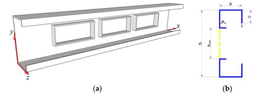
Figure 1.
Lipped channel with stiffened rectangular holes on the web: (a) 3D viewpoint and (b) the perforated cross-section.
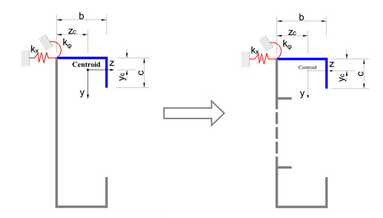
Figure 2.
Analytical model for analysis of the flange–lip system, where it has been highlighted in blue.
In Lau and Hancock’s model [4], which can be seen in Figure 2, and offer the rotational and the lateral elastic restraints of the web onto the flange–lip system, respectively. To ensure that the flange part can be free to translate in the z direction in the buckling mode, the horizontal spring stiffness is assumed to be zero. Therefore, the influence of the web on the flange–lip system leaves only the rotational stiffness . Enlightened by Hancock’s theoretical derivation [5], the elastic critical stress for the distortional buckling of the flange–lip system of flexure members can be written as
in which
where is the elastic critical compressive stress for distortional buckling of the beam; is the modulus of elasticity; is the buckling half wavelength; is the area of the flange–lip system; is the compression flange width; and are the distances from the flange–web junction to the y- and z-axes, respectively; and are the moments of inertia of the flange–lip system area around the z- and y-axes; is the product moment of the flange–lip system area; is the St. Venant torsion constant of the flange–lip system. In this study, holes are only opened on the web, so Hancock’s model can still be considered. The key difficult point in this study that should be given more attention is , i.e., the rotational stiffness corresponding to the web with edge-stiffened holes. As a matter of fact, represents the moment required to produce a unit angle of the flange–web edge by the flange–lip system, and therefore the web plate bending stiffness is an important influencing parameter, because it defines the rotational restraint to the connecting flange. As a consequence, we need to obtain by analyzing a simply supported plate with edge-stiffened holes.
2.2. for a Simply Supported Plate with Edge-Stiffened Rectangular Openings on the Midspan
On the one hand, due to the presence of holes, there will be a reduction in the bending stiffness of the web [3]; on the other hand, because of the edge stiffeners around the holes, there will be a strengthening of the bending stiffness. The presence of the hole edge stiffeners compensates for the loss of the bending stiffness in the web. To quantify the influence of the holes and the edge stiffeners on the web-bending stiffness, we may study the case that there is only one edge-stiffened hole in the web first (see Figure 3).
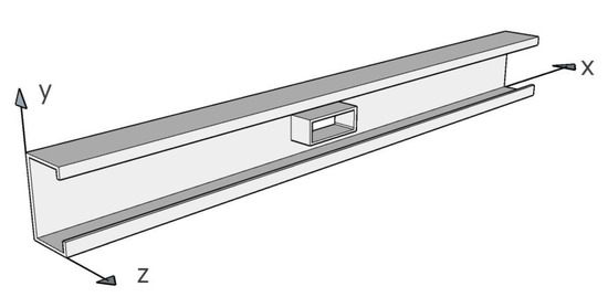
Figure 3.
Three-dimensional perspective of a channel section with only one stiffened hole.
To obtain the analytical formula of , we can start by analyzing a rectangular plate with a single edge-stiffened rectangular hole subjected to distributed moments along the web-top flange joint edge, and further, several assumptions should be considered; i.e.,
- (a)
- The geometric center of the hole coincides with that of the web as shown in Figure 3;
- (b)
- The web plate of the C-section in flexure is treated as a beam simply supported at one end and fixed at the other end (see Figure 4);
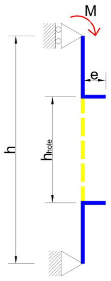 Figure 4. Web model used to determine .
 - (c)
- The derivation of the formula is within the theory of small deformation, so the higher-order terms (above the second order) can be ignored;
- (d)
- The middle surface of the hole stiffeners, which is initially perpendicular to the middle surface of the web, always stays perpendicular to the web midsurface during the deflection of the web plate.
To obtain the rotational stiffness , a uniformly distributed bending moment was applied to the upper side of the web along a half wavelength , as shown in Figure 5, and the corresponding buckling deflection of the web when it deforms can be described by
where is a constant that represents the rotational angle of the upper flange–web edge about the x-axis; is the web depth; notice that the deflection assumed above satisfies the boundary conditions of the web model (see Figure 4).
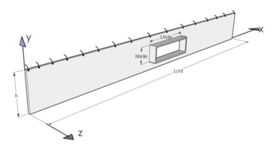
Figure 5.
Apply a line moment to the upper side of the plate with an edge-stiffened hole.
Due to the hole being rectangular, each stiffener can be thought of as a tiny beam spanning the edge of the rectangular hole. Hence, the strain energy of the web with the edge-stiffened hole due to pure bending reads
where denotes the depth of the stiffener (see Figure 4), and is the width of the edge-stiffened hole. The work performed by can be obtained as follows:
according to the principle of least potential energy, i.e., , the relationship between and can be obtained by
after calculation and simplification, and the following formula can be obtained:
We obtained the relationship between and . Because the physical meaning of is the rotational angle around the x-axis as approaches 1, the expression represents the rotational stiffness approximately, and then in this study that can be written explicitly as
where
In Equation (12), the first term represents the rotational stiffness of the web with no hole directly; the second term reflects the reduction effect in bending stiffness on account of the removal of the hole material; the third and fourth terms express the influence of two stiffeners along the longitudinal and transverse distributions of the rectangular hole, respectively. On the other hand, the formula shows that the parameters , , , and are the most significant parameters that represent the effect of openings and edge stiffeners.
To deal with simply supported beams with multiple stiffened rectangular openings evenly distributed longitudinally as shown in Figure 6, i.e., calculating their parameters , we made the following assumptions: each transversal edge stiffener has the same effect; if the beam with multiple unstiffened rectangular openings in is of the same and as another beam with only one unstiffened opening in , both of their strain energies are assumed to be equal. Therefore, we can just modify in Equation (12) properly, and the other terms remain the same. In addition, for a simply supported plate with multiple stiffened rectangular openings is as follows:
where is the number of holes in a one-half wavelength and reads
where is the total number of holes; is the beam length; is the half wavelength in Equation (1) when , and can be estimated by . When we take the normal bending stress on the web () into account, the stiffness of the rotational spring should be modified by multiplying a reduction factor, i.e.,
where stands for the buckling stress of the web plate with edge-stiffened holes in and can be approximately obtained by using the energy method (see Appendix A).
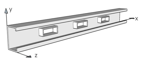
Figure 6.
CFS channel beam with multiple edge-stiffened rectangular openings.
2.3. Critical Load for Pure Distortional Buckling of Lipped Channel Beams with Edge-Stiffened Holes
Substituting Equation (9) into Equation (1), the distortional buckling stress for pure bending can be obtained. As a result of the mind of average, the critical moment of the distortional buckling can be expressed as
where
In the above formula, is the distortional buckling moment of channel-section beams with edge-stiffened holes; is the nominal flexural strength of channel-section beams with edge-stiffened holes subject to distortional buckling after modification; is the yield moment of channel-section beams with no holes when the extreme compression fiber of the gross section is yield; is the second moment of the net area of the lipped channel section with edge-stiffened rectangular holes in the web; is the second moment of the gross area of the lipped channel section without holes in the web.
3. Numerical Analysis
3.1. General
Shell finite element modeling of the CFS channel beams with edge-stiffened web openings, built upon the ANSYS shell181 elements, was employed to calculate the critical loads of buckling. The material properties of the beams are as follows: modulus of elasticity , yield stress and Poisson’s ratio . The detailed modeling process is shown in Section 3.2.
3.2. FE Modeling
Figure 7 plots the typical shell finite element meshes used for the modeling of the perforated/nonperforated CFS channel beams, where the shell-181, a 4-node thick shell element with six DOFs per node, was used to construct the FE model, and the average edge size of the meshes equals 5 mm.
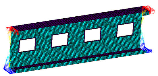
Figure 7.
Finite element mesh of a perforated beam and the force boundary condition.
3.3. Boundary Conditions
The beams were assumed to be pinned–pinned at both ends and subjected to pure bending about their principal axis. We applied the displacement boundary conditions through linking the DOFs associated with nodes on an end section to a virtual single node. Assuming that the lateral displacements of all nodes on the sections at both ends are zero, the lateral displacements and the rotational displacements about the longitudinal axis are zero as well. To avoid the appearance of rigid displacement along the longitudinal axis, the longitudinal axial displacement of the key point, which locates in the neutral plane of one end of the sections, is assumed to be zero. The bending moments were applied by a distributed force along the center line of the two end sections, where the forces were assumed to be equably distributed on the two flange lines, i.e., for the top and for the bottom, and linearly distributed on the web line, i.e., from to ; the lip line is from to for the top and from to for the bottom, (see Figure 6). Then, the linear elastic analyses of the beam with edge-stiffened web holes were carried out, and the effects of the edge stiffeners around web holes on the elastic buckling loads and failure mode shapes of the beam are discussed.
3.4. Validation of the Analytical Model
To obtain the minimum eigenvalue representing the critical stress of a distortional buckling, the section size should be carefully selected. After a series of simple finite element analyses of CFS channel-section beams without holes, we selected four sections from them, and their geometry dimensions are listed in Table 1, the hole length to beam length ratio, and the hole depth to web depth ratio, , ranged from 0.1 to 0.7. From the distortional buckling curves of CFS channel-section beams with edge-stiffened holes (see Figure 8), represents the distortional buckling moments of CFS channel-section beams with edge-stiffened holes, and denotes the yield moments of CFS beams without holes. From the result of the FE analysis, the distortional buckling mode is dominant in all kinds of buckling modes when the length of the beam varies from 200 mm to 1600 mm in four selected sections.

Table 1.
Geometric properties of the chosen channel sections.
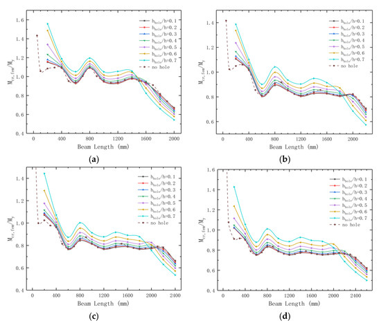
Figure 8.
Distortional buckling curves of CFS channel-section beams with edge-stiffened holes ( My is the yield moment of CFS beams; ). (a) Section A (h = 180, b = 60, c = 20, t = 2.0, and e = 9). (b) Section B (h = 200, b = 70, c = 20, t = 2.2, and e = 9). (c) Section C (h = 240, b = 75, c = 20, t = 2.5, and e = 9). (d) Section D (h = 300, b = 80, c = 20, t = 3.0, and e = 9).
As shown in Figure 8, it is obvious that the four distortional curves have similar variation tendencies, but beams exhibiting global buckling are of different lengths for the four sections. Figure 8 also shows that the critical moment of global buckling decreases as increases because the properties of the section changed when there were several openings with edge-stiffened holes on the beam webs; in turn, the overall flexural stiffness of the beam decreases. On the contrary, the critical moment of distortional buckling increases along with the increase in the ratio of the hole depth to web depth once a threshold value is exceeded; this trend implies that the enhancement effect of edge stiffeners outweighs the reduction effect of the holes on the distortional buckling moment. In addition, the member length on the beam behavior is dominated by the global buckling mode will decrease with the increase in the , so the dominant buckling mode may be changed once the hole depth to web depth becomes large enough. Due to the simplification of strain energies for holes far from the center of the half wave, the error may increase when more than one hole is involved in a distortional half wave, and it may also increase when the size of the holes increases to a certain degree in the half wave, and this can be estimated via the comparison of the results of the critical moments of the distortional buckling between the presented formula and the FE analyses.
Figure 9 shows several typical distortional buckling modes; in most cases, the wavelengths of different half waves are equal for the distortional buckling mode in the beam with even-distributed edge-stiffened rectangular holes.
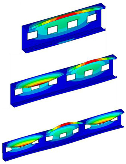
Figure 9.
Typical distortional buckling modes.
Figure 10 shows the overall process for predicting the critical distortional buckling moments in a simply supported beam with given section properties and stiffening hole dimensions. At first, we calculated the number of edge-stiffened holes in a one-half wavelength by Equation (27) and estimated the half wavelength, and secondly, we obtained all the coefficients associated with by using Equations (14) and(15) and Equations (17) and (26); thirdly, we calculated the rotational stiffness from Equation (28), and finally, we predicted the nominal moment of distortional buckling by Equation (29).
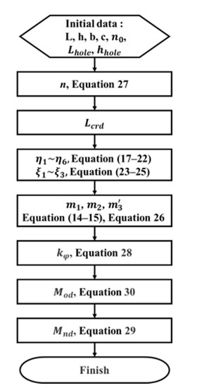
Figure 10.
Calculation process of the critical moment of distortion buckling mode.
To verify the accuracy of the formula, a comparison of the critical moments for the distortional buckling between the formula and FEM should be conducted. Figure 11 shows the comparison of the critical moments of the distortional buckling; and were obtained from the proposed analytical solution and the finite element analysis for different values of ratios, respectively. Figure 11 indicates that the critical distortional buckling moments calculated by the proposed analytical solution are highly consistent with those calculated by the FE analysis, where the mean deviation of all the cases is only 6.59%, and the maximum deviation is 17.76% for the case that in section A. The mean values of are 0.89, 0.95, 0.98, and 0.99 for the four sections. For section A, the analytical method predicting the critical moment of distortional buckling is a little conservative; for other sections, some cases occur with unconservative results, while the overall errors are small in all cases. Generally, the analytical method is quite applicative when , and it is worth mentioning that the analytical method predicting the critical moment of distortional buckling is a little bit conservative when the hole depth to web depth ratio , and this implies that the actual effect of edge stiffeners increases as increases.
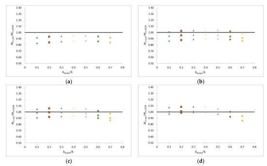
Figure 11.
Comparison of critical moments of distortional buckling between formula and FEM. (a) Section A (h = 180, b = 60, c = 20, t = 2.0, and e = 9). (b) Section B (h = 200, b = 70, c = 20, t = 2.2, and e = 9). (c) Section C (h = 240, b = 75, c = 20, t = 2.5, and e = 9). (d) Section D (h = 300, b = 80, c = 20, t = 3.0, and e = 9).
4. Effect of Edge-Stiffener Length on the Critical Moment of Distortional Buckling
To find out the optimized stiffener length to the web length ratio , this article studied the critical moment in the above four sections, whose stiffener length to web length ratio ranged from 0.1 to 0.9, and the hole depth to web depth ranged from 0.1 to 0.7. The results are shown in Figure 12.
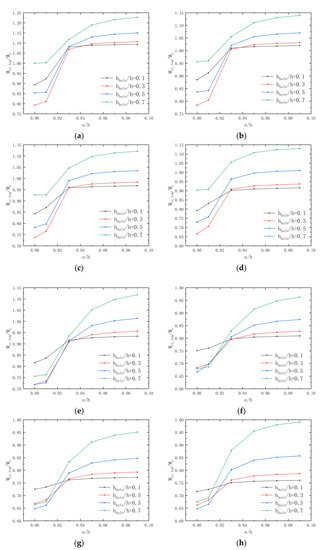
Figure 12.
Effect of ratio on moment capacity. (a) Section A (L = 400). (b) Section B (L = 400). (c) Section C (L = 400). (d) Section D (L = 400). (e) Section A (L = 600). (f) Section B (L = 600). (g) Section C (L = 600). (h) Section D (L = 600).
Globally, it is observed that the critical distortional moment of beams presents a growing tendency as increases, but the growth slows down when exceeds a threshold value, and the threshold value is about 0.05 in the four selected sections. In addition, increases slowly in Figure 12; i.e., the enhancement effect of edge stiffeners is not quite significant when the hole depth to the web depth ratio is small (e.g., ). When , a small increase in the critical moment of beams with different ratios means that the enhancement effect of the edge stiffeners on the critical moment of beams is inferior to the weakening effect of holes on the critical moment of beams, and when , the critical moment of beams increases as increases; in other words, the effect of the edge stiffener outweighs the effect of holes, and the change in regularity for the distortional buckling moment is governed by hole edge-stiffener length.
5. Conclusions
This paper presents an analytical and numerical investigation of the critical moment of CFS beams with edge-stiffened rectangular web holes. A relatively accurate analytical equation that predicts the critical moment of CFS beams with edge-stiffened rectangular web holes is obtained by the energy method. The moment capacity of the CFS channel beams with edge-stiffened web holes obtained from the analytical method was compared with the finite element analysis. From the comparison, the results of the analytical method and finite element method showed fair consistency, and the mean values of are 0.89, 0.95, 0.98, and 0.99 for the four sections, and the mean deviation of all the cases is only 6.59%.
Moreover, the parametric study in this paper shows some conclusions as follows:
- (a)
- The existence of edge stiffeners will not change the overall trend of elastic buckling.
- (b)
- When the enhancement of edge stiffeners dominates the change in critical distortional moments, the critical moment of distortional buckling increases as increases; on the contrary, the critical moment of global buckling decreases as increases.
- (c)
- In the distortional buckling mode, the critical distortional moments of beams with edge-stiffened holes generally increase as increases, but the enhancement effect of edge stiffeners declines when exceeds the threshold of about 0.05.
- (d)
- The critical distortional moments of beams with edge-stiffened holes increase as increases when the value reaches the threshold of about 0.03, which means the enhancement of edge stiffeners dominates the change of critical distortional moments in this situation.
6. Recommendation
This article deals with the prediction of the distortional buckling loads of CFS channel members with edge-stiffened rectangular web openings undergoing major-axis pure flexure. The authors advise that researchers could pay more attention to more analytical, experimental, and numerical studies on CFS components with edge-stiffened web holes in compression, flexure, and shear or under combined forces or other complex loading conditions, so that relatively simple calculation formulas for the calculations of the pure buckling critical loads, which are necessary for the DSM design of CFS members, can be obtained.
Author Contributions
Conceptualization, L.D. and C.L.; methodology, L.D. and C.L.; validation, C.L.; formal analysis, C.L.; investigation, C.L.; writing—original draft preparation, C.L.; writing—review and editing, L.D.; visualization, L.D. and C.L.; supervision, L.D.; project administration, L.D. and C.L.; funding acquisition, L.D. All authors have read and agreed to the published version of the manuscript.
Funding
This research is funded by the National Natural Science Foundation of China (No. 52178147).
Data Availability Statement
Not applicable.
Acknowledgments
The authors are thankful for the great support from the State Key Laboratory of Ocean Engineering, Shanghai Jiao Tong University and Shanghai Key Laboratory for Digital Maintenance of Buildings and Infrastructure, Department of Civil Engineering, Shanghai Jiao Tong University. The financial support provided by the National Natural Science Foundation of China (NSFC) from the Chinese government is greatly acknowledged.
Conflicts of Interest
The authors declare no conflict of interest. The funders had no role in the design of the study; in the collection, analyses, or interpretation of data; in the writing of the manuscript; or in the decision to publish the results.
Abbreviations
| A | = | Cross-sectional area of flange–lip system |
| b | = | plate width |
| c | = | depth of lip stiffener |
| D | = | plate flexural rigidity per unit width |
| E | = | Young’s modulus |
| e | = | edge stiffener length |
| h | = | depth of web |
| hhole | = | depth of web hole |
| Iy, Iz | = | second moments of area of flange–lip system about the y- and z-axes |
| Ig | = | second moment of the gross area of lipped channel section without holes |
| Iyz | = | product second moment of area of flange–lip system about the y- and z-` |
| yc, zc | = | y, z distances of centroid from the flange–web junction (see Figure 2) |
| J | = | St. Venant torsional constant |
| L | = | beam length |
| Lcrd | = | distortional buckling half wavelength of beam |
| Lhole | = | length of web hole |
| Mcr | = | critical elastic distortional buckling moment |
| t | = | thickness |
| ν | = | Poisson’s ratio |
Appendix A. Buckling Stress of Web Plates with Folds
The deflection of the web when it buckles is assumed as follows:
where is the buckling stress of web plates, and the boundary conditions are also described as aforementioned. The strain energy of the web plate with multiple edge-stiffened rectangular holes can be obtained as follows:
the work performed by web-bending stresses can be estimated as follows:
by using the variation of with respect to , which is to be determined, and of the plate multiple stiffened rectangular openings can be obtained the formula as follows:
where
References
- AISI S100-16; North American Specification for the Design of Cold-Formed Steel Structural Members. American Iron and Steel Institute(AISI): Washington, DC, USA, 2016.
- EN1993-1-3; Design of Steel Structures. Part 1–3: General Rules- Supplementary Rules for Cold-Formed Members and Sheeting. BSI: Brussels, Belgium, 2006.
- AS/NZS 4600:2018; Cold-Formed Steel Structures. Australia/New Zealand Standard (AS/NZS): Wellington, New Zealand, 2018.
- Lau, S.C.W.; Hancock, G.J. Distortional Buckling Formulas for Channel Columns. J. Struct. Eng. 1987, 113, 1063–1078. [Google Scholar] [CrossRef]
- Hancock, G.J. Design for distortional buckling of flexural members. Thin-Walled Struct. 1997, 27, 3–12. [Google Scholar] [CrossRef]
- Li, L.-Y.; Chen, J.-K. An analytical model for analysing distortional buckling of cold formed steel sections. Thin-Walled Struct. 2008, 46, 1430–1436. [Google Scholar] [CrossRef]
- Schafer, B.W.; Pekoz, T. Laterally braced cold-formed steel flexural members with edge stiffened flanges. J. Struct. Eng. 1999, 125, 118–127. [Google Scholar] [CrossRef]
- Schafer, B.W. Local, Distortional, and Euler Buckling of Thin-Walled Columns. J. Struct. Eng. 2002, 128, 289–299. [Google Scholar] [CrossRef]
- Liu, Z.; Yang, Y.; Zhou, X.; He, Z. Unified formulae for critical load and unified DSM expressions for pinned-end and fixed-end columns exhibiting pure distortional buckling. Thin-Walled Struct. 2020, 151, 106746. [Google Scholar] [CrossRef]
- Zhou, X.; Liu, Z.; He, Z. General distortional buckling formulae for both fixed-ended and pinned-ended C-section columns. Thin-Walled Struct. 2015, 94, 603–611. [Google Scholar] [CrossRef]
- Yu, N.-T.; Kim, B.; Yuan, W.-B.; Li, L.-Y.; Yu, F. An analytical solution of distortional buckling resistance of cold-formed steel channel-section beams with web openings. Thin-Walled Struct. 2019, 135, 446–452. [Google Scholar] [CrossRef]
- Yu, N.-T.; Kim, B.; Li, L.-Y.; Hong, W.-J.; Yuan, W.-B. Distortional buckling of perforated cold-formed steel beams subject to uniformly distributed transverse loads. Thin-Walled Struct. 2020, 148, 106569. [Google Scholar] [CrossRef]
- Yu, N.-T.; Kim, B.; Huang, X.-H.; Yuan, W.-B.; Ye, R.; Wu, L.; Le, J.-J. Analytical solution for flange/web distortional buckling of cold-formed steel beams with circular web perforations. Mech. Adv. Mater. Struct. 2021, 29, 3463–3473. [Google Scholar] [CrossRef]
- Yuan, W.-B.; Yu, N.-T.; Li, L.-Y. Distortional buckling of perforated cold-formed steel channel-section beams with circular holes in web. Int. J. Mech. Sci. 2017, 126, 255–260. [Google Scholar] [CrossRef]
- Cardosoa, D.C.T.; de Salles, G.C.; Batista, E.d.M.; Gonçalves, P.B. Explicit equations for distortional buckling of cold-formed steel lipped channel columns. Thin-Walled Struct. 2017, 119, 925–933. [Google Scholar] [CrossRef]
- Moen, C.D. Direct Strength Design of Cold-Formed Steel Members with Perforations. Ph.D. Thesis, Johns Hopkins University, Baltimore, MD, USA, 2008. [Google Scholar]
- Moen, C.D.; Schafer, B.W. Experiments on cold-formed steel columns with holes. Thin-Walled Struct. 2008, 46, 1164–1182. [Google Scholar] [CrossRef]
- Moen, C.D.; Schafer, B.W. Extending Direct Strength Design to Cold-Formed Steel Beams with Holes. In Proceedings of the Twentieth International Specialty Conference on Cold-Formed Steel Structures, St. Louis, MO, USA, 3–4, November 2010. [Google Scholar]
- Moen, C.D.; Schafer, B.W. Elastic buckling of cold-formed steel columns and beams with holes. Eng. Struct. 2009, 31, 2812–2824. [Google Scholar] [CrossRef]
- Moen, C.D.; Schafer, B.W. Elastic buckling of thin plates with holes in compression or bending. Thin-Walled Struct. 2009, 47, 1597–1607. [Google Scholar] [CrossRef]
- Moen, C.D.; Schafer, B.W. Direct Strength Method for Design of Cold-Formed Steel Columns with Holes. Eng. Struct. 2011, 137, 559–570. [Google Scholar] [CrossRef]
- Moen, C.D.; Schudlich, A.; Heyden, A. Experiments on cold-formed steel C-section joists with unstiffened web holes. Struct. Eng. 2013, 139, 695–704. [Google Scholar] [CrossRef]
- Chen, B.; Roy, K.; Uzzaman, A.; Raftery, G.M.; Nash, D.; Clifton, G.C.; Pouladi, P.; Lim, J.B. Effects of edge-stiffened web openings on the behaviour of cold-formed steel channel sections under compression. Thin-Walled Struct. 2019, 144, 106307. [Google Scholar] [CrossRef]
- Chen, B.; Roy, K.; Uzzaman, A.; Lim, J.B.P. Moment capacity of cold-formed channel beams with edge-stiffened web holes, un-stiffened web holes and plain webs. Thin-Walled Struct. 2020, 157, 107070. [Google Scholar] [CrossRef]
- Chen, B.; Roy, K.; Uzzaman, A.; Raftery, G.M.; Lim, J.B.P. Parametric study and simplified design equations for cold-formed steel channels with edge-stiffened holes under axial compression. J. Constr. Steel Res. 2020, 172, 106161. [Google Scholar] [CrossRef]
- Chen, B.; Krishanu, R.; Fang, Z.; Uzzaman, A.; Pham, C.H.; Raftery, G.M.; Lim, J.B.P. Shear Capacity of Cold-Formed Steel Channels with Edge-Stiffened Web Holes, Unstiffened Web Holes, and Plain Webs. J. Struct. Eng. 2022, 148, 04021268. [Google Scholar] [CrossRef]
- Chen, B.; Krishanu, R.; Fang, Z.; Uzzaman, A.; Chi, Y.; Lim, J.B.P. Web crippling capacity of fastened cold-formed steel channels with edge-stiffened web holes, un-stiffened web holes and plain webs under two-flange loading. Thin-Walled Struct. 2021, 163, 10766. [Google Scholar] [CrossRef]
- Yu, C. Cold-formed steel flexural member with edge stiffened holes: Behavior, optimization, and design. J. Constr. Steel Res. 2012, 71, 210–218. [Google Scholar] [CrossRef]
- Kanthasamy, E.; Thirunavukkarasu, K.; Poologanathan, K.; Gatheeshgar, P.; Todhunter, S.; Suntharalingam, T.; Ishqy, M.F.M. Shear behaviour of doubly symmetric rectangular hollow flange beam with circular edge-stiffened openings. Eng. Struct. 2022, 250, 113366. [Google Scholar] [CrossRef]
- Moen, C.; Yu, C. Elastic Buckling of Thin-Walled Structural Components with Edge-Stiffened Holes. In Proceedings of the 51st AIAA/ASME/ASCE/AHS/ASC Structures, Structural Dynamics, and Materials Conference 18th, Orlando, FL, USA, 12–15 April 2010. [Google Scholar]
- Grey, C.N.; Moen, C.D. Elastic Buckling Simplified Methods for Cold-Formed Columns and Beams with Edge-Stiffened Holes. In Proceedings of the Annual Stability Conference Structural Stability Research Council, Pittsburgh, PA, USA, 10–14 May 2011. [Google Scholar]
- Fang, Z.; Roya, K.; Chen, B.; Sham, C.-W.; Hajirasouliha, I.; Lim, J.B.P. Deep learning-based procedure for structural design of cold-formed steel channel sections with edge-stiffened and un-stiffened holes under axial compression. Thin-Walled Struct. 2021, 166, 108076. [Google Scholar] [CrossRef]
- Dai, Y.; Roy, K.; Fang, Z.; Chen, B.; Raftery, G.M.; Lim, J.B.P. A novel machine learning model to predict the moment capacity of cold-formed steel channel beams with edge-stiffened and un-stiffened web holes. J. Build. Eng. 2022, 53, 104592. [Google Scholar] [CrossRef]


Disclaimer/Publisher’s Note: The statements, opinions and data contained in all publications are solely those of the individual author(s) and contributor(s) and not of MDPI and/or the editor(s). MDPI and/or the editor(s) disclaim responsibility for any injury to people or property resulting from any ideas, methods, instructions or products referred to in the content. |
© 2022 by the authors. Licensee MDPI, Basel, Switzerland. This article is an open access article distributed under the terms and conditions of the Creative Commons Attribution (CC BY) license (https://creativecommons.org/licenses/by/4.0/).