Author Contributions
Conceptualization, L.Z.; methodology, L.Z.; validation, B.H.; formal analysis, C.G. and R.S.; investigation, C.G.; resources, L.Z.; data curation, B.H. and Q.-C.T.; writing—original draft preparation, R.S.; writing—review and editing, C.G.; visualization, C.G. and Q.-C.T.; supervision, L.Z.; project administration, L.Z. and C.G. All authors have read and agreed to the published version of the manuscript.
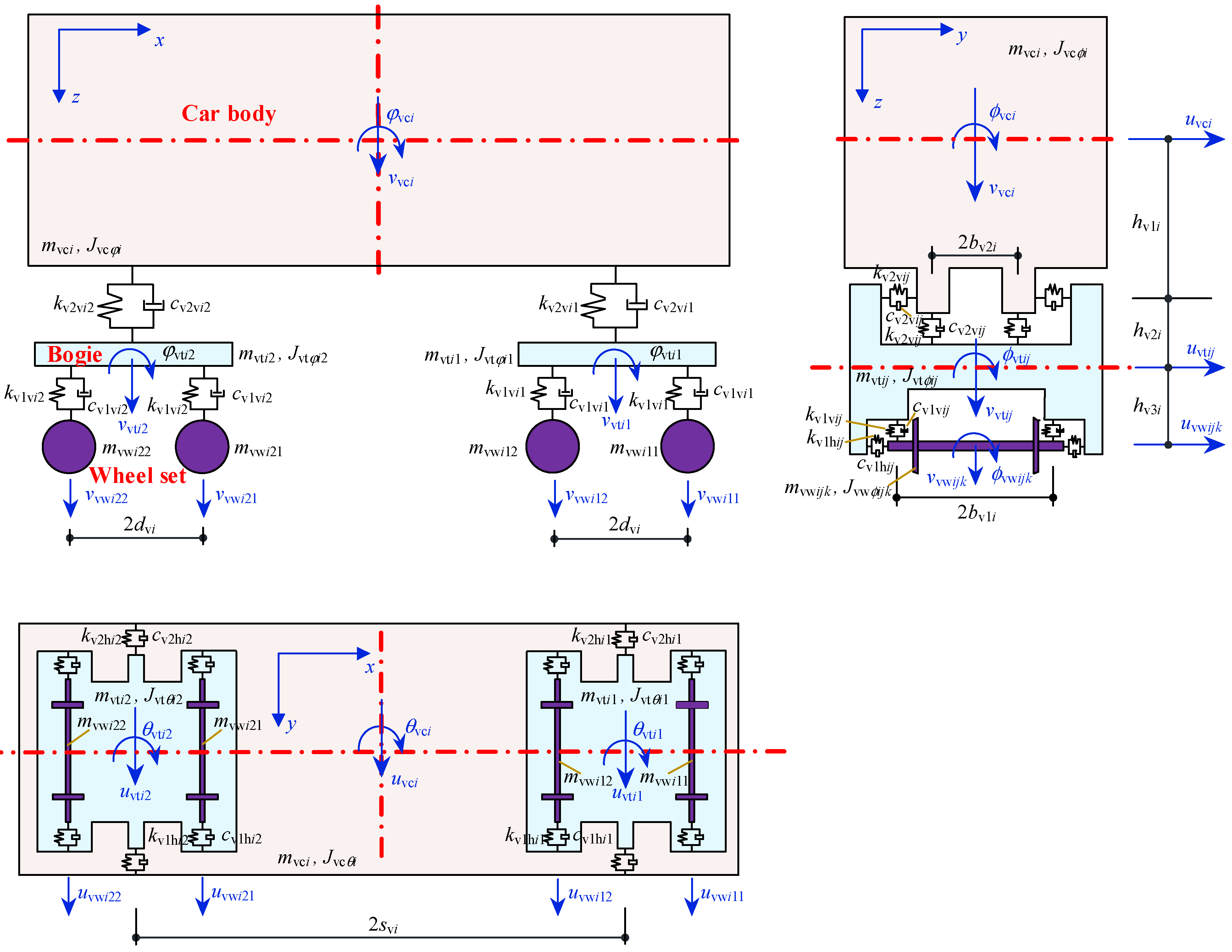
Figure 1.
27 DOF train model [
33].
Figure 1.
27 DOF train model [
33].
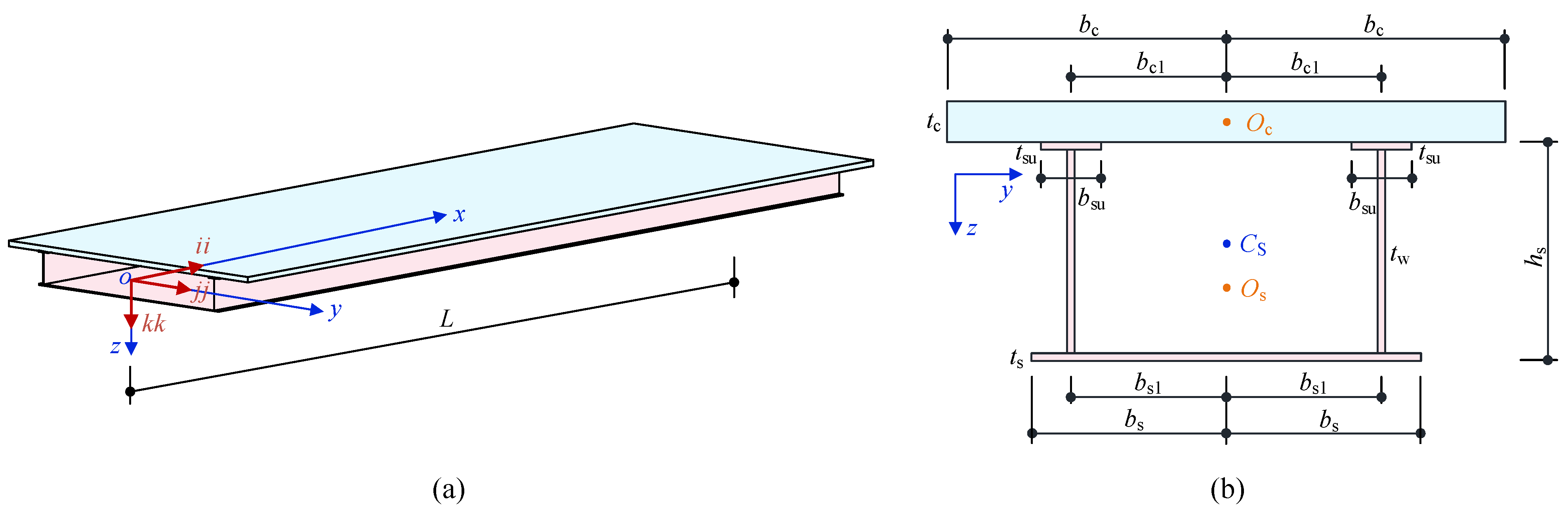
Figure 2.
Diagrams of steel-concrete composite box-girder bridges [
33] (
a) Three-dimension; (
b) Cross-section.
Figure 2.
Diagrams of steel-concrete composite box-girder bridges [
33] (
a) Three-dimension; (
b) Cross-section.
Figure 3.
Change in vertical displacement of the composite box-girder bridge with time (a) Longitudinal distribution; (b) Change with time.
Figure 3.
Change in vertical displacement of the composite box-girder bridge with time (a) Longitudinal distribution; (b) Change with time.
Figure 4.
Comparison between the calculated and the fitted displacement distribution curves.
Figure 4.
Comparison between the calculated and the fitted displacement distribution curves.
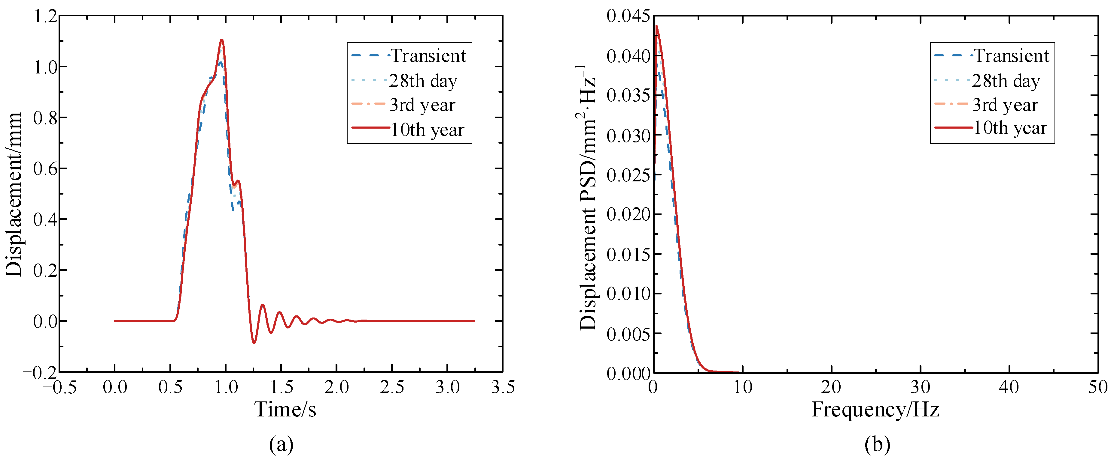
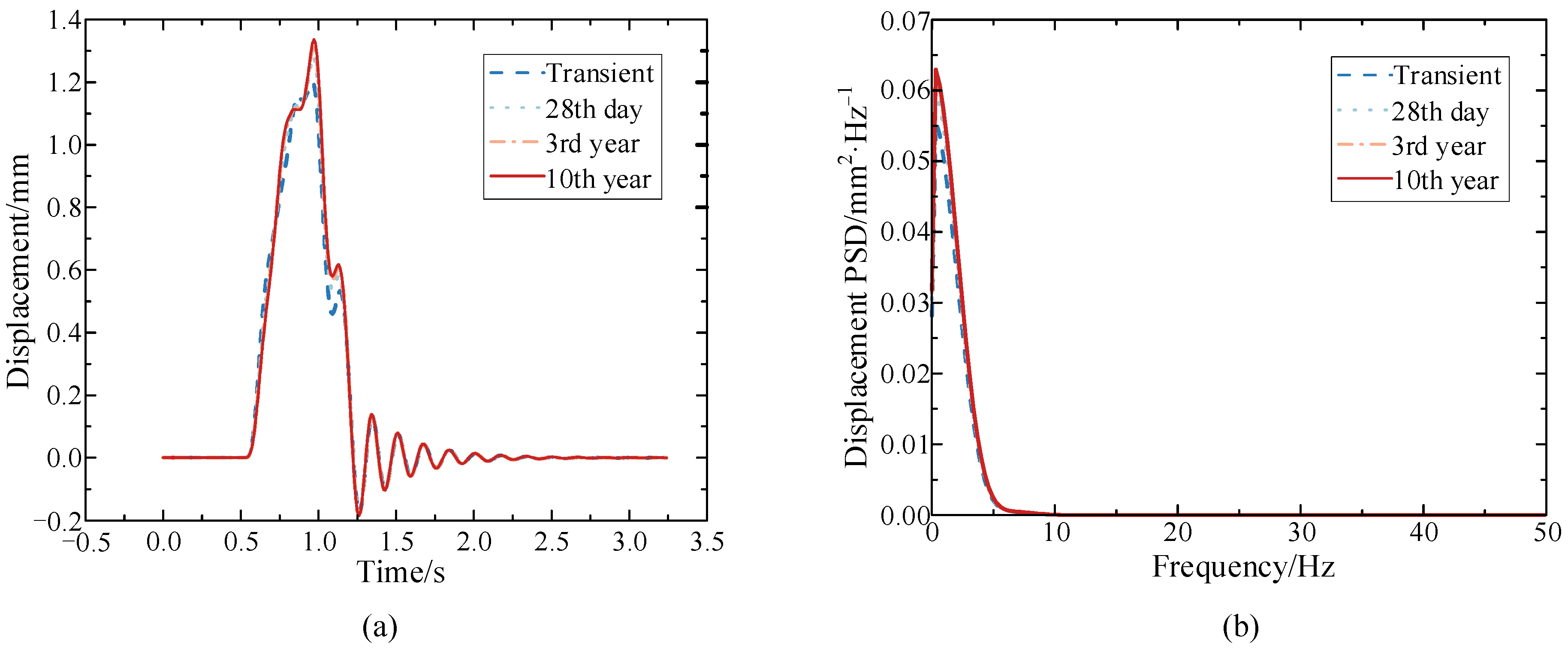
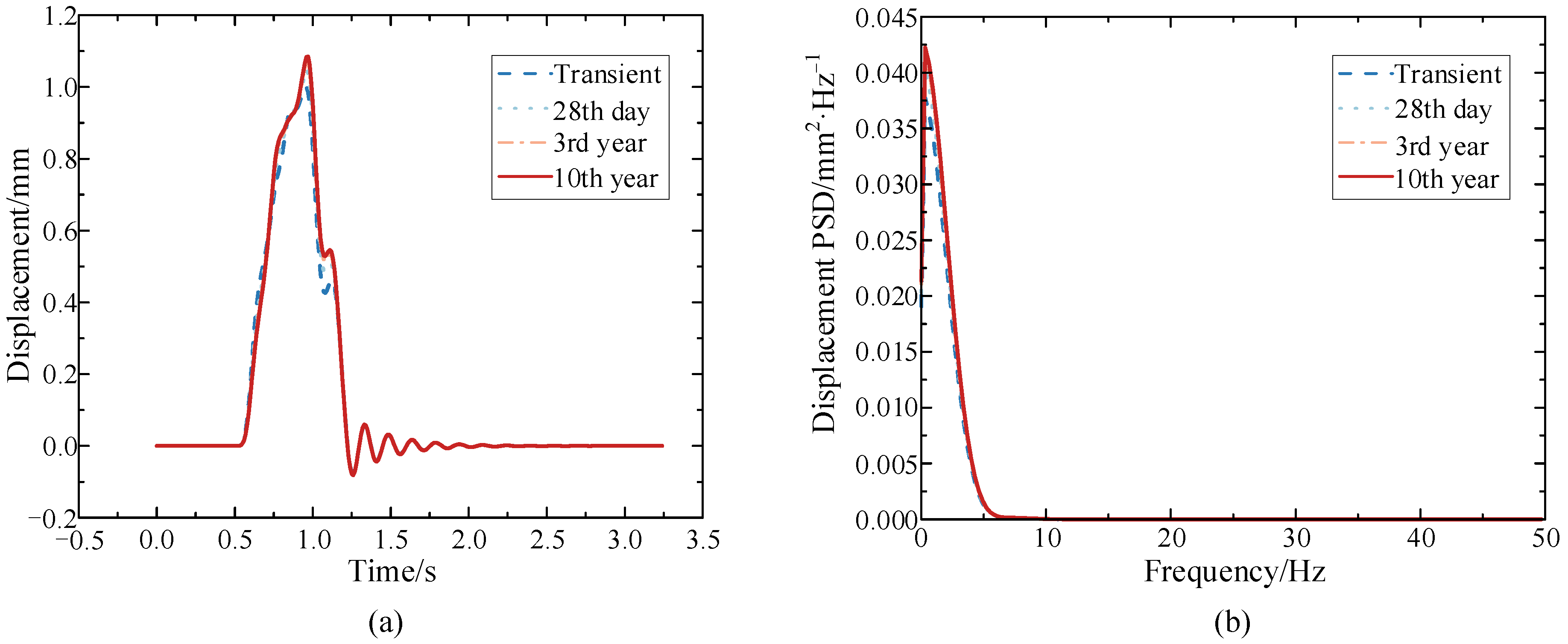
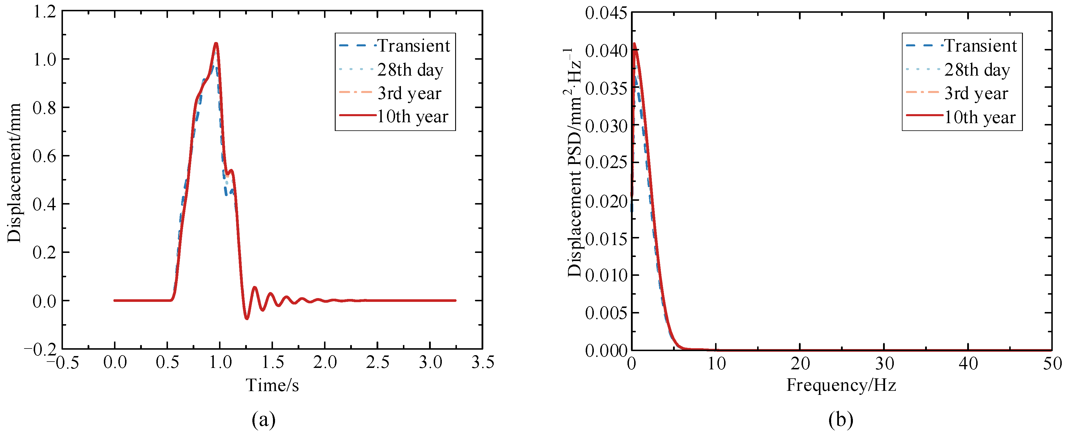
Figure 5.
Vertical displacement of the mid-span section of the composite box-girder bridge at different operation times (a) Time history; (b) Power spectral density.
Figure 5.
Vertical displacement of the mid-span section of the composite box-girder bridge at different operation times (a) Time history; (b) Power spectral density.
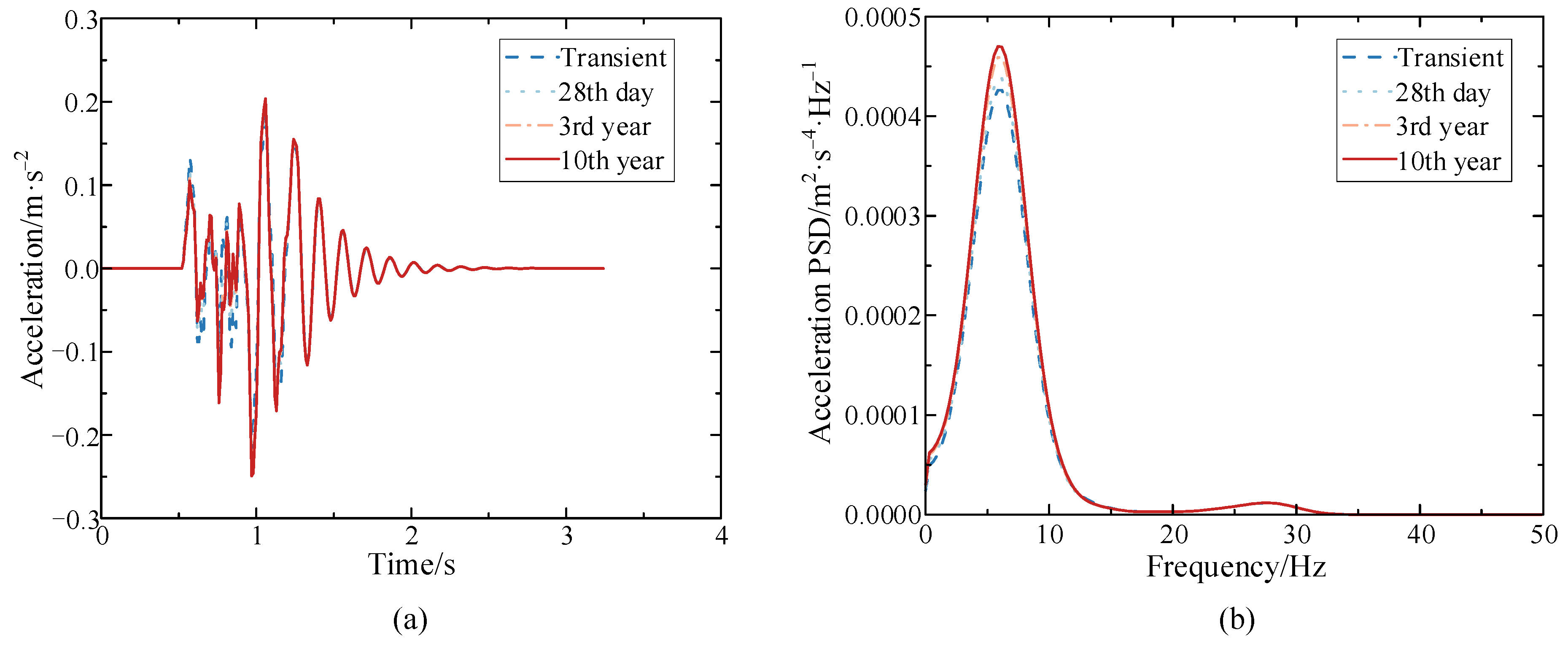
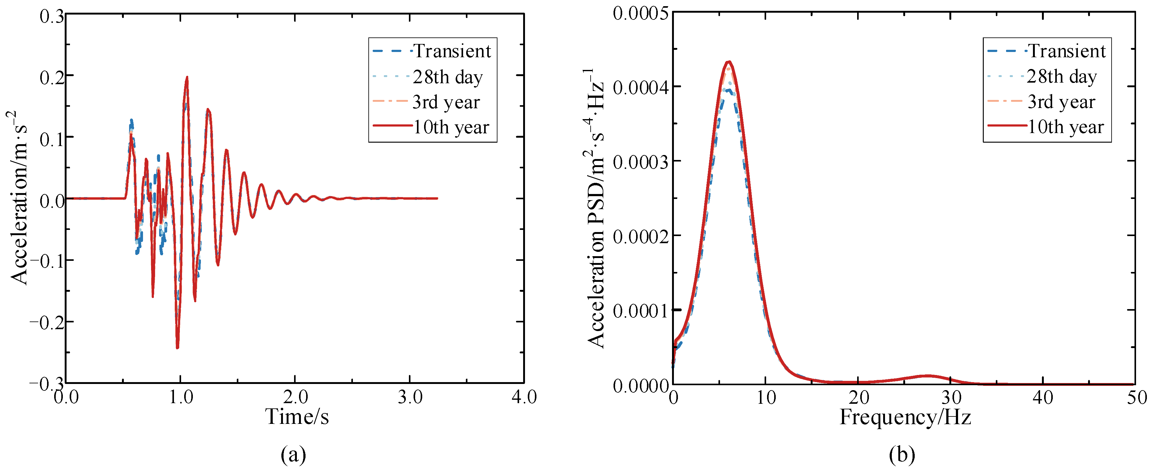
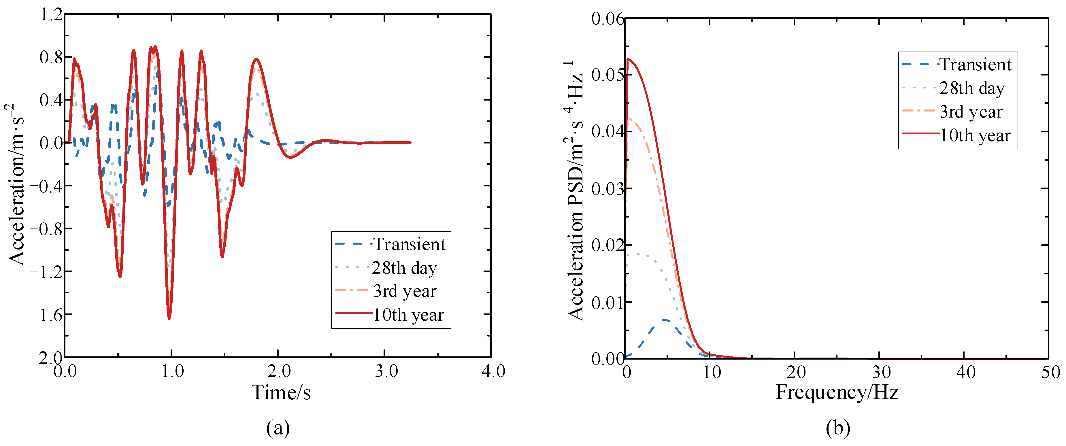
Figure 6.
Vertical acceleration of the mid-span section of the composite box-girder bridge at different operation times (a) Time history; (b) Power spectral density.
Figure 6.
Vertical acceleration of the mid-span section of the composite box-girder bridge at different operation times (a) Time history; (b) Power spectral density.
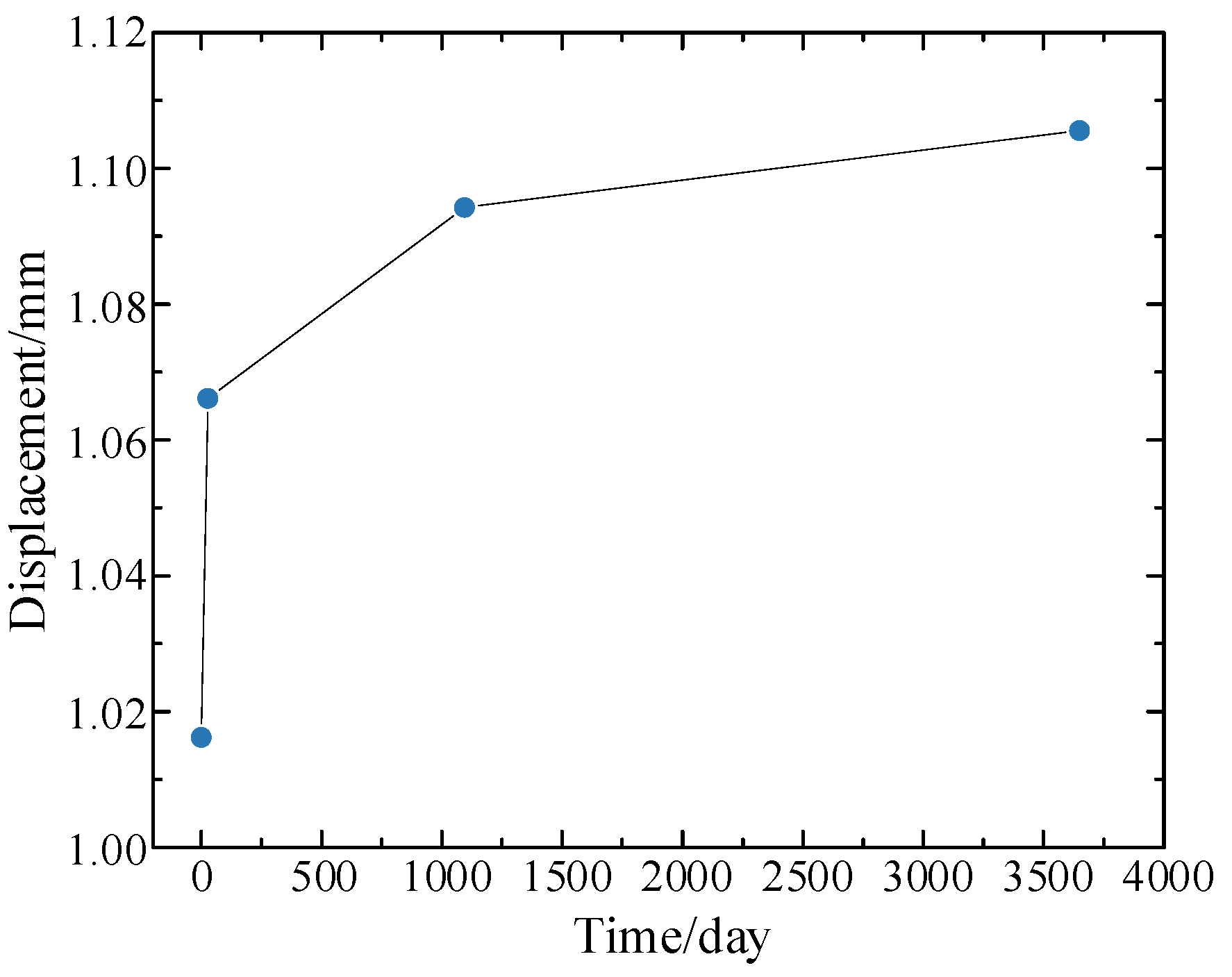
Figure 7.
Maximum vertical displacements at the mid-span section of the composite box-girder bridge at various operation times.
Figure 7.
Maximum vertical displacements at the mid-span section of the composite box-girder bridge at various operation times.
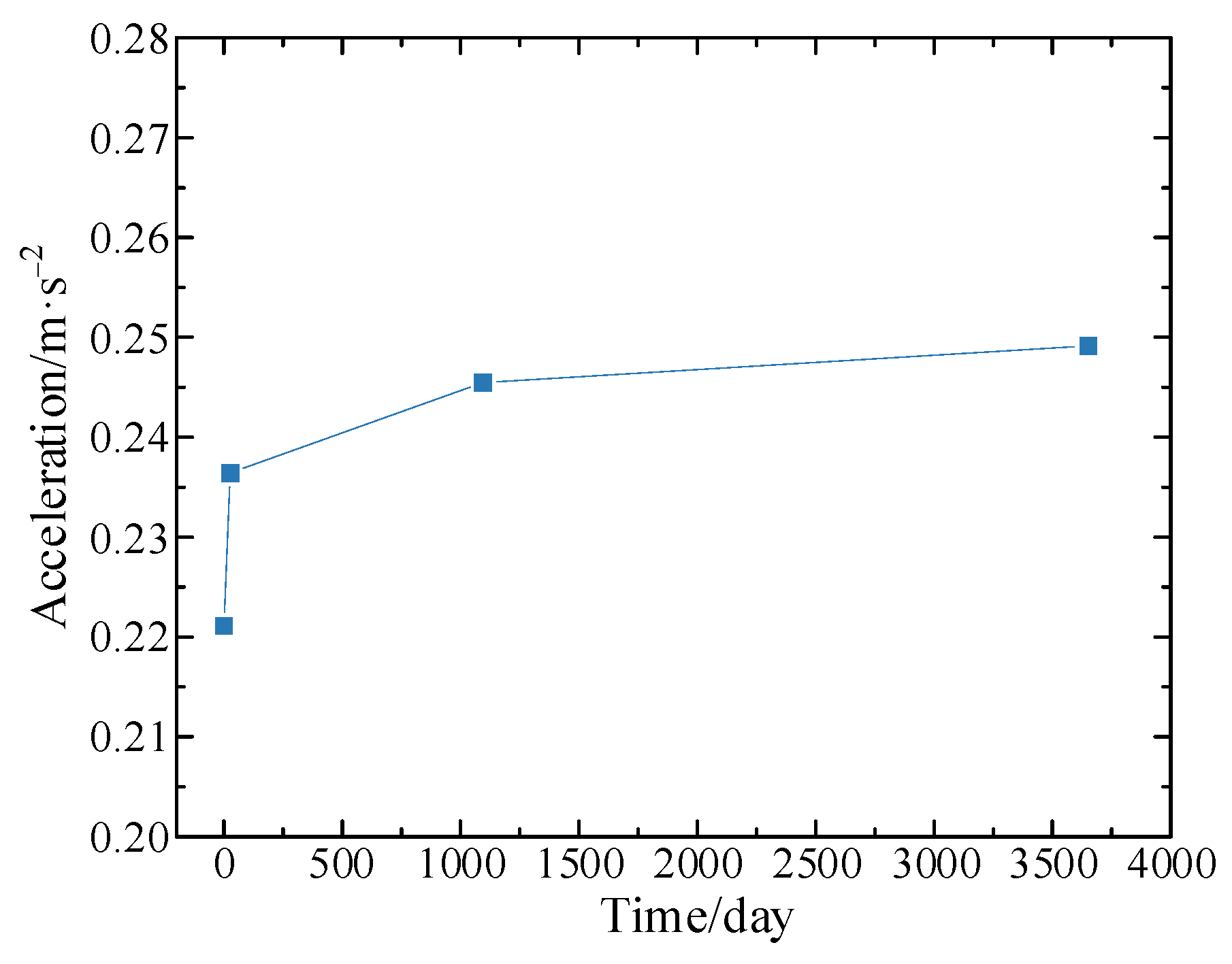
Figure 8.
Maximum vertical accelerations at the mid-span section of the composite box-girder bridge at various operation times.
Figure 8.
Maximum vertical accelerations at the mid-span section of the composite box-girder bridge at various operation times.
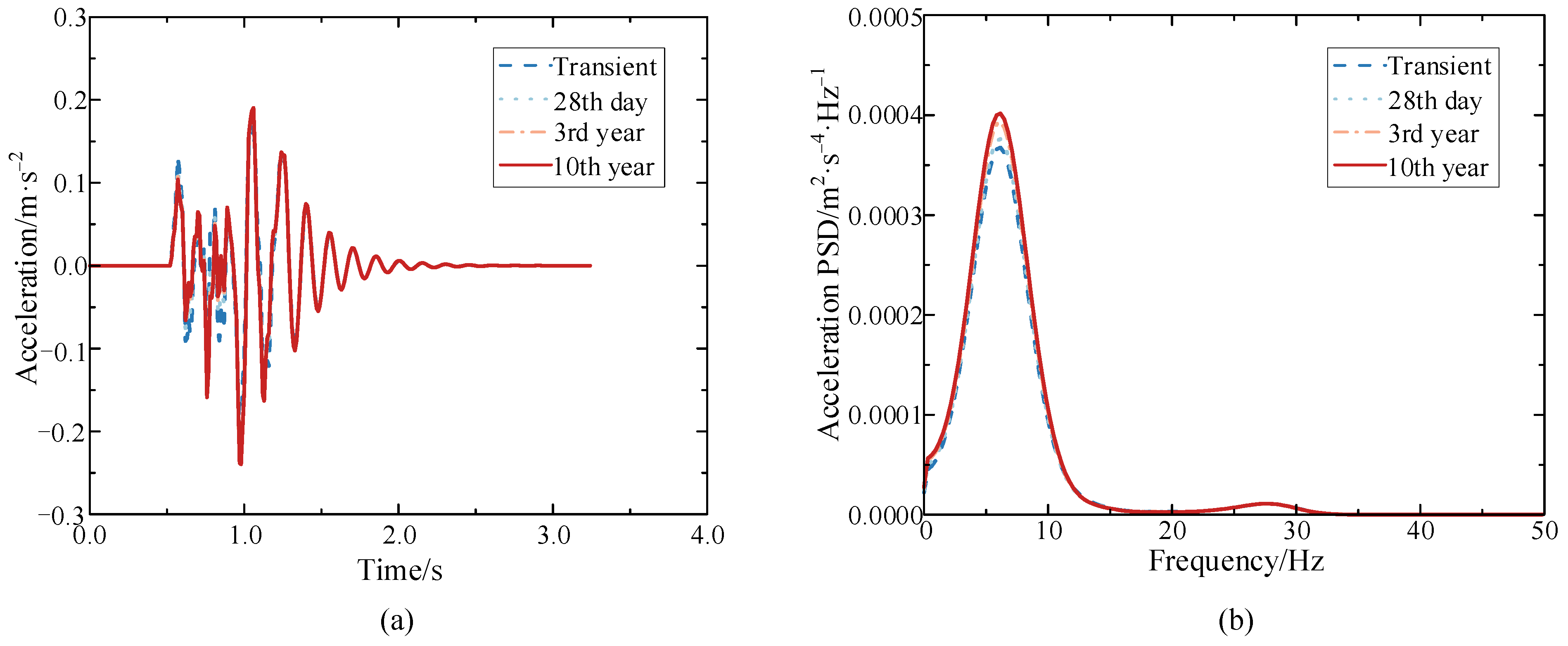
Figure 9.
Vertical acceleration of the train at different operation times (a) Time history; (b) Power spectral density.
Figure 9.
Vertical acceleration of the train at different operation times (a) Time history; (b) Power spectral density.
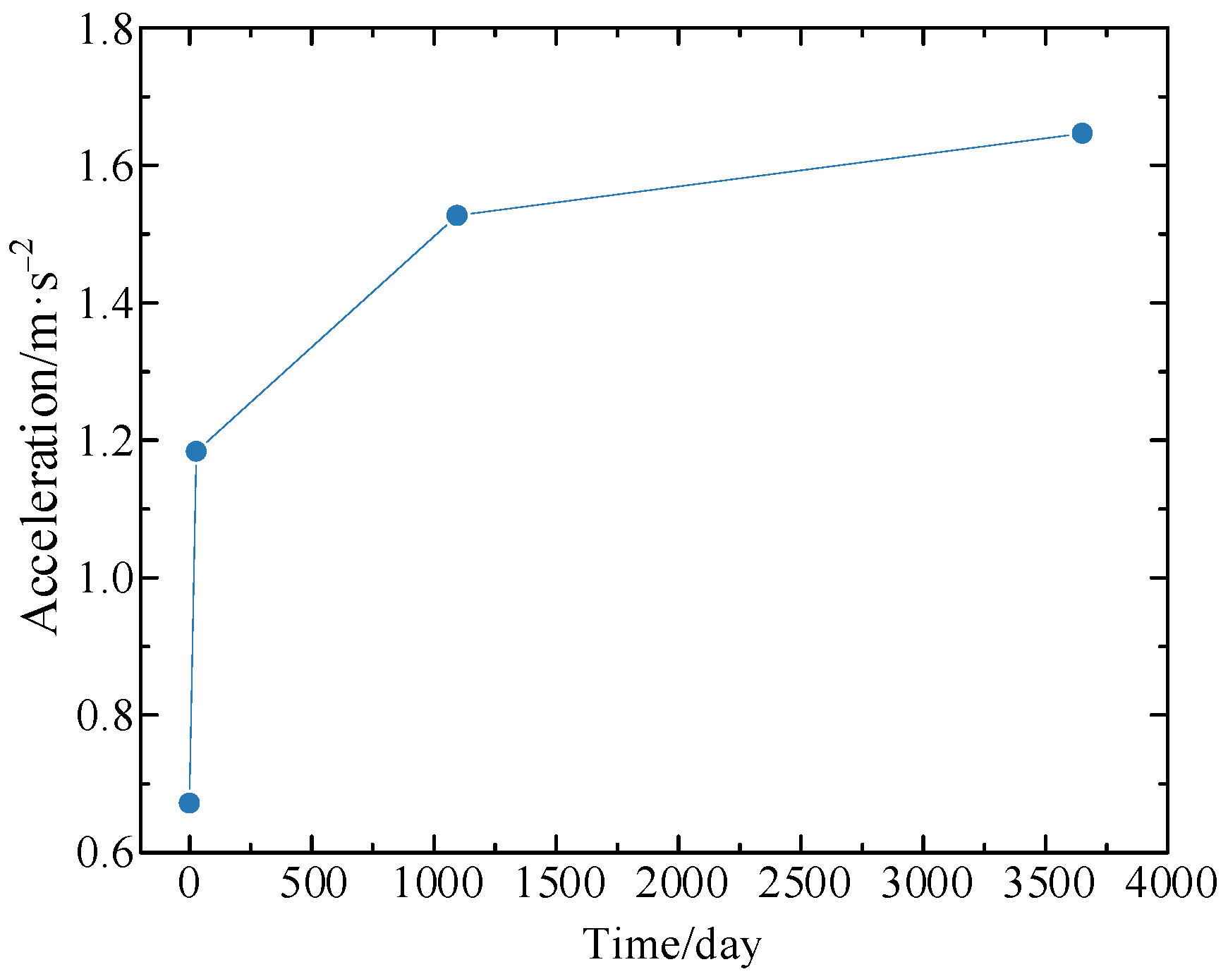
Figure 10.
Maximum vertical accelerations of the train at various operation times.
Figure 10.
Maximum vertical accelerations of the train at various operation times.
Figure 11.
Vertical displacement of the mid-span section of the composite girder bridge when ρsh = 1 kN/mm2 (a) Time history; (b) Power spectral density.
Figure 11.
Vertical displacement of the mid-span section of the composite girder bridge when ρsh = 1 kN/mm2 (a) Time history; (b) Power spectral density.
Figure 12.
Vertical acceleration at the mid-span section of the composite girder bridge when ρsh = 1 kN/mm2 (a) Time history; (b) Power spectral density.
Figure 12.
Vertical acceleration at the mid-span section of the composite girder bridge when ρsh = 1 kN/mm2 (a) Time history; (b) Power spectral density.
Figure 13.
Vertical displacement at the mid-span section of the composite girder bridge when ρsh = 100 kN/mm2 (a) Time history; (b) Power spectral density.
Figure 13.
Vertical displacement at the mid-span section of the composite girder bridge when ρsh = 100 kN/mm2 (a) Time history; (b) Power spectral density.
Figure 14.
Vertical acceleration at the mid-span section of the composite girder bridge when ρsh = 100 kN/mm2 (a) Time history; (b) Power spectral density.
Figure 14.
Vertical acceleration at the mid-span section of the composite girder bridge when ρsh = 100 kN/mm2 (a) Time history; (b) Power spectral density.
Figure 15.
The maximum vertical displacements at the mid-span section of the composite girder bridge with various operation times.
Figure 15.
The maximum vertical displacements at the mid-span section of the composite girder bridge with various operation times.
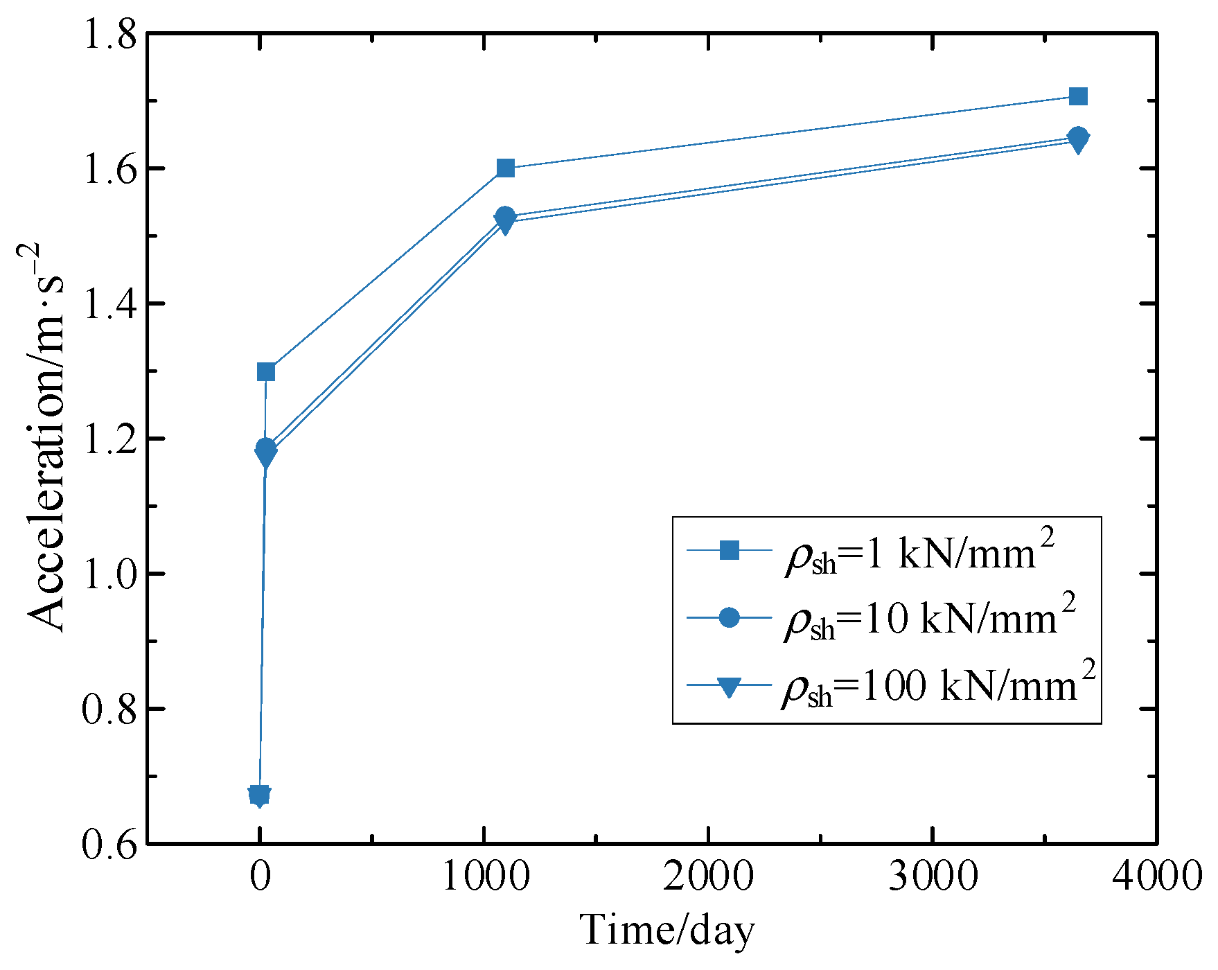
Figure 16.
The maximum vertical accelerations at the mid-span section of the composite girder bridge with various operation times.
Figure 16.
The maximum vertical accelerations at the mid-span section of the composite girder bridge with various operation times.
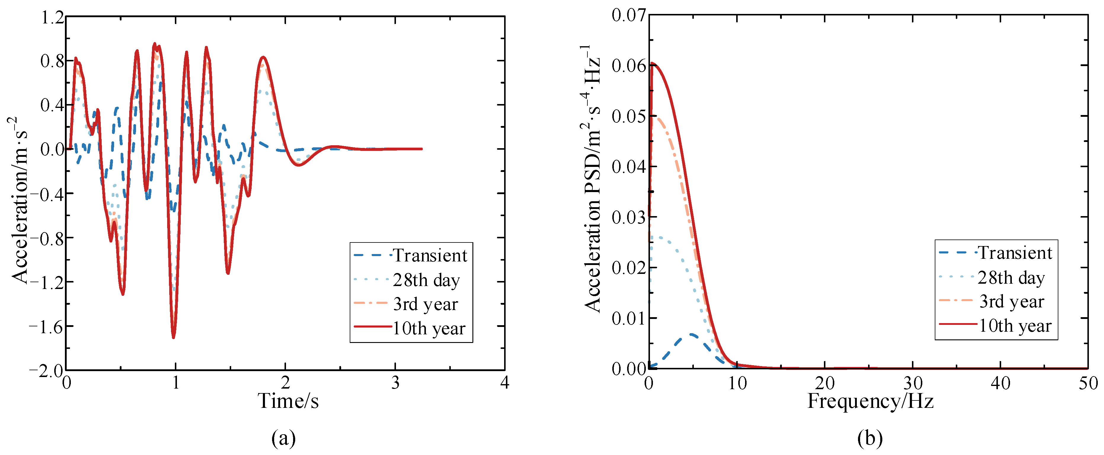
Figure 17.
Vertical acceleration of the train body when ρsh = 1 kN/mm2 (a) Time history; (b) Power spectral density.
Figure 17.
Vertical acceleration of the train body when ρsh = 1 kN/mm2 (a) Time history; (b) Power spectral density.
Figure 18.
Vertical acceleration of the train body when ρsh = 100 kN/mm2 (a) Time history; (b) Power spectral density.
Figure 18.
Vertical acceleration of the train body when ρsh = 100 kN/mm2 (a) Time history; (b) Power spectral density.
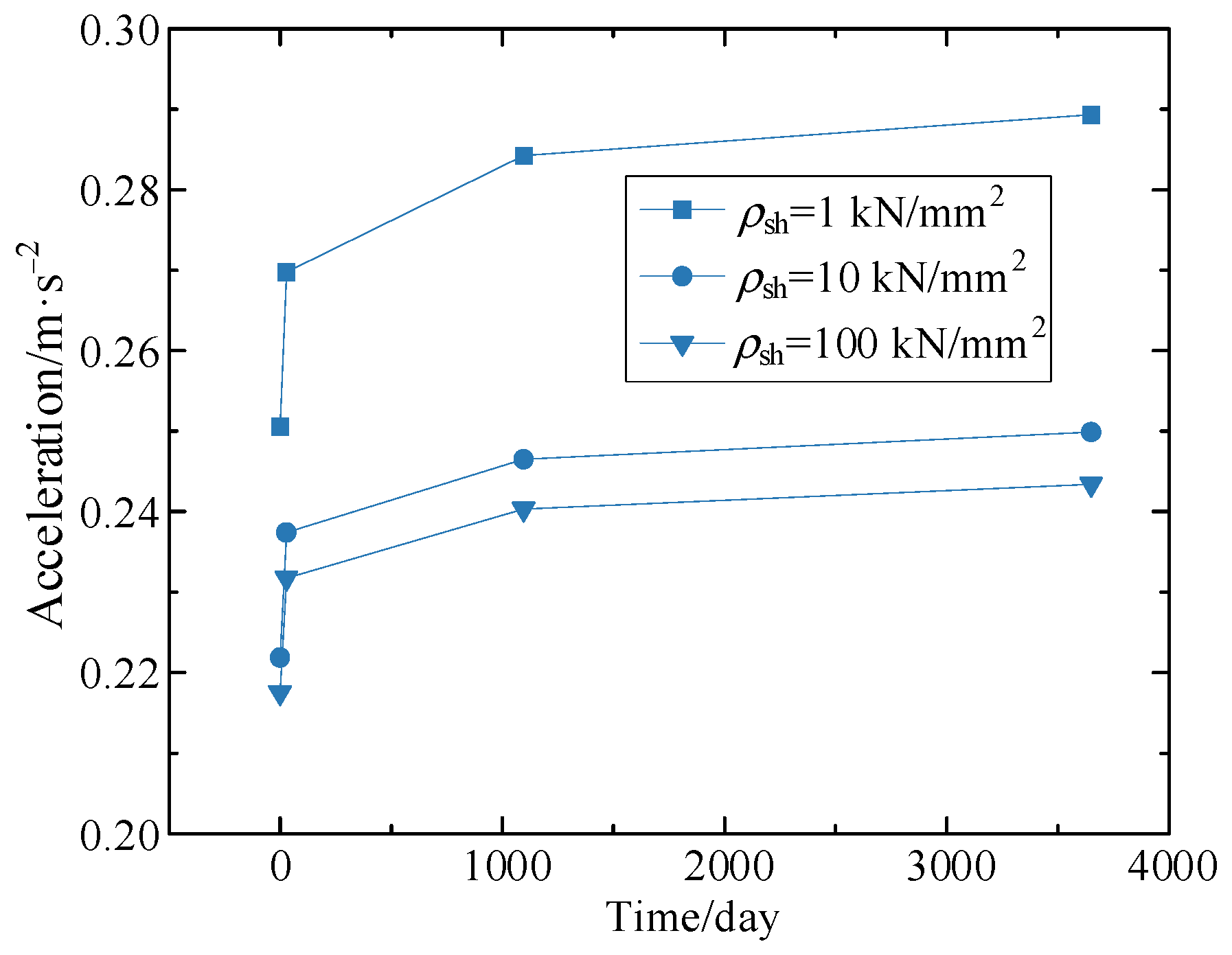
Figure 19.
Maximum vertical accelerations of the train body for various shear connection stiffnesses.
Figure 19.
Maximum vertical accelerations of the train body for various shear connection stiffnesses.
Figure 20.
Vertical displacement at the mid-span section of the composite bridge without considering the shear lag effect (a) Time history; (b) Power spectral density.
Figure 20.
Vertical displacement at the mid-span section of the composite bridge without considering the shear lag effect (a) Time history; (b) Power spectral density.
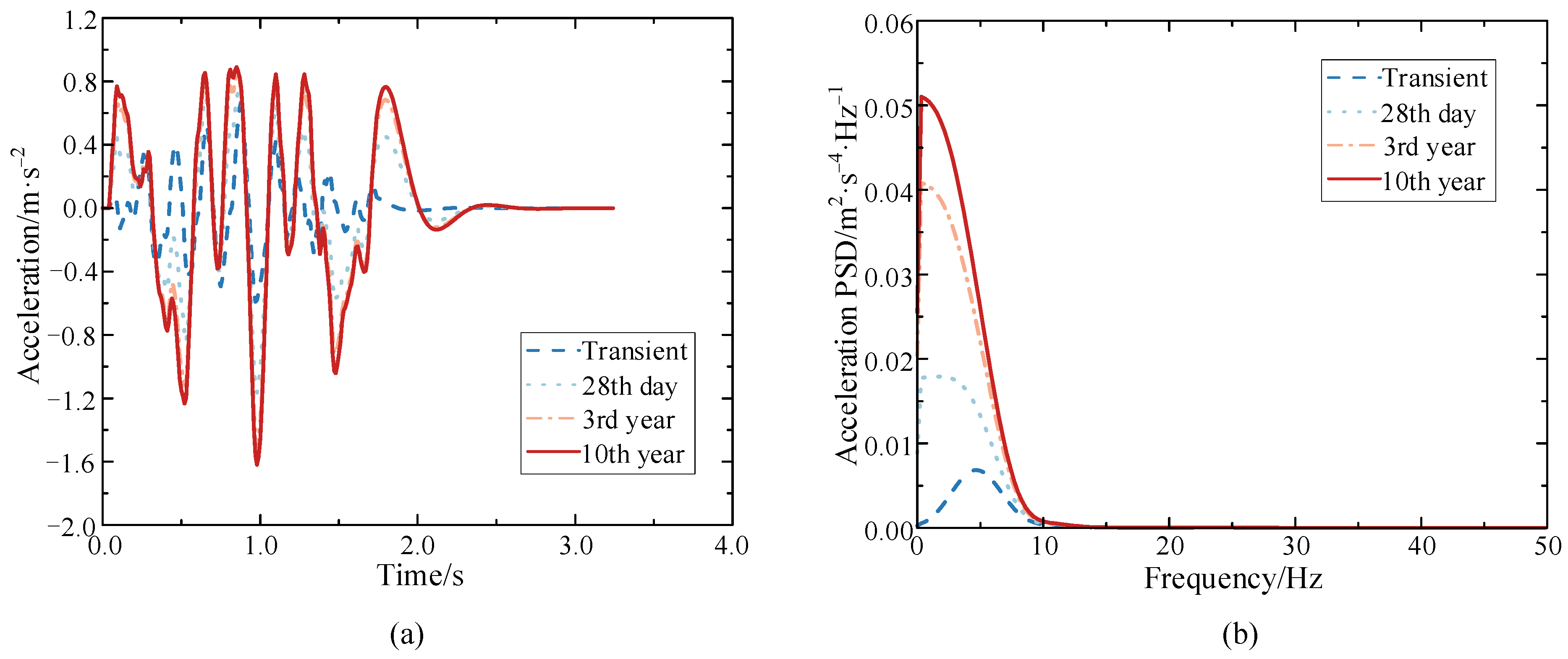
Figure 21.
Vertical acceleration at the mid-span section of the composite bridge without considering the shear lag effect (a) Time history; (b) Power spectral density.
Figure 21.
Vertical acceleration at the mid-span section of the composite bridge without considering the shear lag effect (a) Time history; (b) Power spectral density.
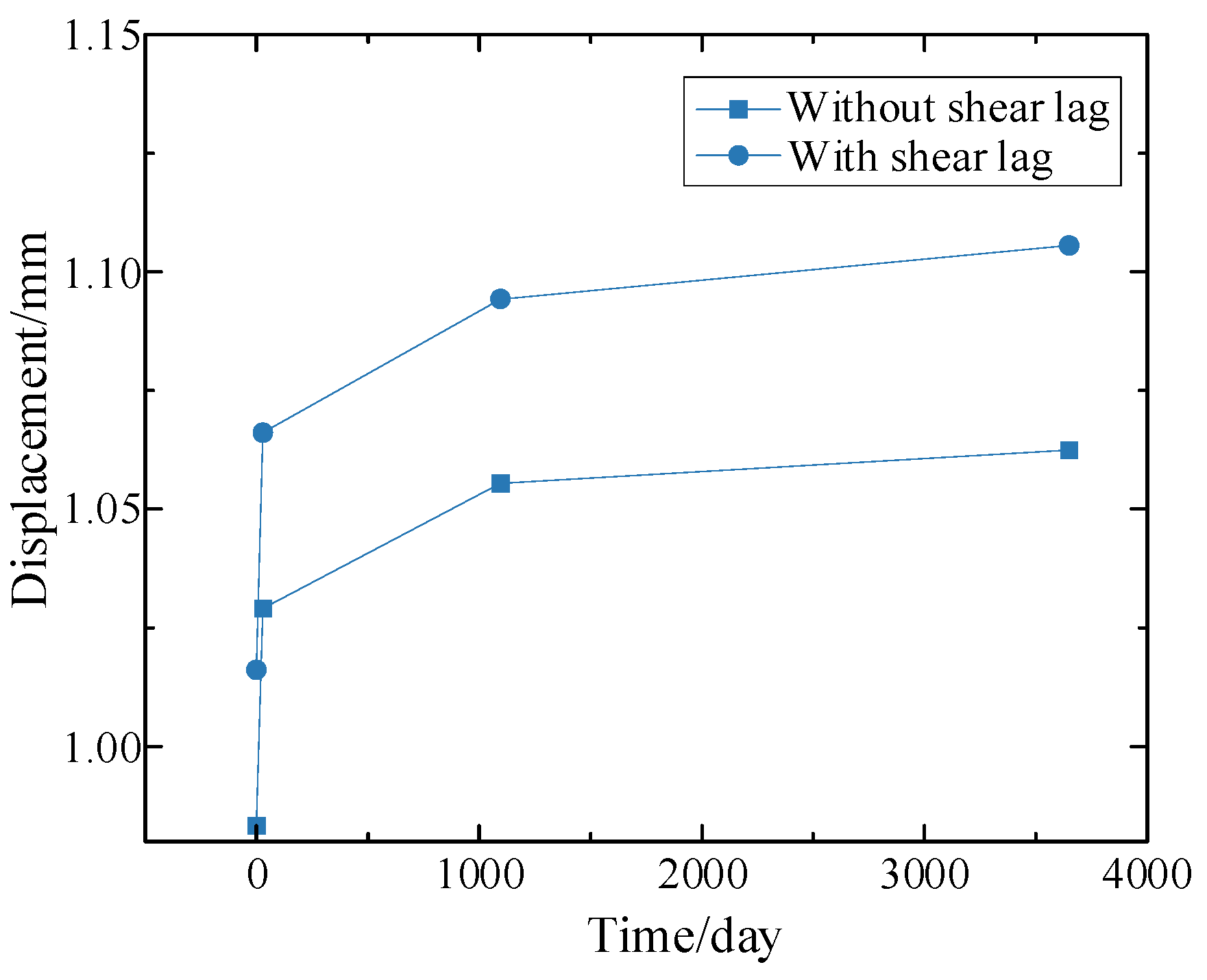
Figure 22.
Maximum vertical displacements of the composite bridge without considering the shear lag effect with operation times.
Figure 22.
Maximum vertical displacements of the composite bridge without considering the shear lag effect with operation times.
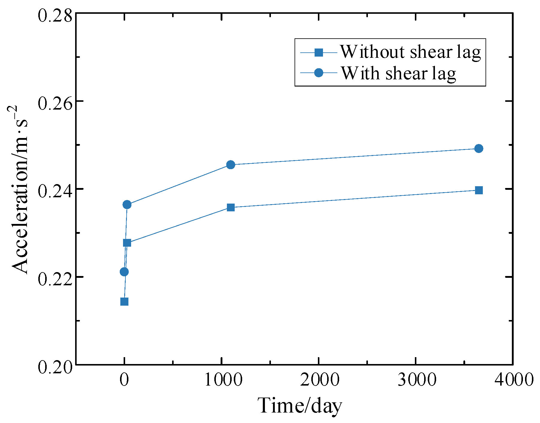
Figure 23.
Maximum vertical accelerations of the composite bridge without considering the shear lag effect with operation times.
Figure 23.
Maximum vertical accelerations of the composite bridge without considering the shear lag effect with operation times.
Figure 24.
Vertical acceleration of the train body without considering the shear lag (a) Time history; (b) Power spectral density.
Figure 24.
Vertical acceleration of the train body without considering the shear lag (a) Time history; (b) Power spectral density.
Figure 25.
Maximum vertical accelerations of the train body with and without considering the shear lag with operation time.
Figure 25.
Maximum vertical accelerations of the train body with and without considering the shear lag with operation time.
Table 1.
Dynamic parameters of the CRH2 train.
Table 1.
Dynamic parameters of the CRH2 train.
| Item | Unit | Motor Car | Trailer |
|---|
| mvc | t | 39.6 | 34.4 |
| Jvcθ | t·m² | 128.304 | 111.456 |
| Jvcϕ | t·m² | 1940.4 | 1453.4 |
| Jvcψ | t·m² | 1673.1 | 1685.6 |
| mvt | t | 3.2 | 2.6 |
| Jvtθ | t·m² | 2.592 | 2.106 |
| Jvtϕ | t·m² | 3.2 | 2.6 |
| Jvtψ | t·m² | 1.752 | 1.423 |
| mvw | t | 2 | 2.1 |
| Jvwθ | t·m² | 0.72 | 0.756 |
| kv1h | kN/m | 7000 | 7000 |
| kv1v | kN/m | 1000 | 1000 |
| kv2h | kN/m | 360 | 360 |
| kv2v | kN/m | 400 | 400 |
| cv1h | kN·s/m | 0 | 0 |
| cv1v | kN·s/m | 40 | 40 |
| cv2h | kN·s/m | 100 | 100 |
| cv2v | kN·s/m | 200 | 200 |
| dv | m | 2.5 | 2.5 |
| bv1 | m | 2 | 2 |
| bv2 | m | 2 | 2 |
| sv | m | 17.5 | 17.5 |
| hv1 | m | 1.7 | 1.7 |
| hv2 | m | 0.14 | 0.14 |
| hv3 | m | 0.28 | 0.28 |
| hv4 | m | 1.645 | 1.645 |
Table 2.
Geometric section of steel-concrete composite box-girder bridges.
Table 2.
Geometric section of steel-concrete composite box-girder bridges.
| bc/mm | bc1/mm | tc/mm | bs/mm | bs1/mm | ts/mm | bsu/mm | tsu/mm | hs/mm | tw/mm | ρsh/kN·mm−2 |
|---|
| 5000 | 3000 | 300 | 3400 | 3000 | 40 | 500 | 30 | 3500 | 30 | 10 |
Table 3.
Material properties and load parameters of the simply supported composite box-girder bridge.
Table 3.
Material properties and load parameters of the simply supported composite box-girder bridge.
| fck/MPa | υc | Es/MPa | υs | RH | tsh/day | ρc/kg·m−3 | ρs/kg·m−3 | pz/kN·m−1 |
|---|
| 50 | 0.2 | 2.06 × 10⁵ | 0.3 | 0.85 | 7 | 2500 | 7850 | 140 |
Table 4.
Specific value of each coefficient in the fitting Equation (1).
Table 4.
Specific value of each coefficient in the fitting Equation (1).
| i | ai | bi | ci |
|---|
| 1 | 36.38 | 0.02842 | −0.1458 |
| 2 | 13.02 | 0.1573 | −1.646 |
| 3 | 22.92 | 0.05556 | 1.356 |
| 4 | 7.978 | 0.08141 | 2.937 |
| 5 | 2.932 | 0.3101 | −1.454 |
| 6 | 1.266 | 0.4631 | −1.265 |
| 7 | 0.6798 | 0.6136 | −0.9305 |
Table 5.
Characteristic frequency relative to the vertical acceleration at the mid-span vertical acceleration of the second span for different operation stages.
Table 5.
Characteristic frequency relative to the vertical acceleration at the mid-span vertical acceleration of the second span for different operation stages.
| Operation Stage | Transient | 28th Day | 3rd Year | 10th Year |
|---|
| 1st characteristic frequency/Hz | 6.15 | 5.85 | 5.85 | 5.85 |
| 2nd characteristic frequency/Hz | 27.69 | 27.69 | 27.69 | 27.69 |
Table 6.
Characteristic frequencies at the mid-span vertical acceleration of the second span with different shear connection stiffnesses.
Table 6.
Characteristic frequencies at the mid-span vertical acceleration of the second span with different shear connection stiffnesses.
| Operation Stage | Transient | 28th Day | 3rd Year | 10th Year |
|---|
| ρsh = 1 kN/mm2 | Characteristic frequency/Hz | 5.85 | 5.85 | 5.85 | 5.85 |
| Characteristic frequency/Hz | 27.38 | 27.38 | 27.38 | 27.38 |
| ρsh = 10 kN/mm2 | Characteristic frequency/Hz | 6.15 | 5.85 | 5.85 | 5.85 |
| Characteristic frequency/Hz | 27.69 | 27.69 | 27.69 | 27.69 |
| ρsh = 100 kN/mm2 | Characteristic frequency/Hz | 6.15 | 6.15 | 6.15 | 6.15 |
| Characteristic frequency/Hz | 27.69 | 27.69 | 27.69 | 27.69 |
Table 7.
Characteristic frequencies of train body vertical acceleration for different shear connection stiffnesses.
Table 7.
Characteristic frequencies of train body vertical acceleration for different shear connection stiffnesses.
| Operation Stage | Transient | 28th Day | 3rd Year | 10th Year |
|---|
| ρsh = 1 kN/mm2 | Characteristic frequency/Hz | 4.61 | 0.31 | 0.31 | 0.31 |
| ρsh = 10 kN/mm2 | Characteristic frequency/Hz | 4.61 | 1.54 | 0.31 | 0.31 |
| ρsh = 100 kN/mm2 | Characteristic frequency/Hz | 4.61 | 1.54 | 0.31 | 0.31 |
Table 8.
Characteristic frequencies of the mid-span vertical acceleration of the second span with and without considering the shear lag effect.
Table 8.
Characteristic frequencies of the mid-span vertical acceleration of the second span with and without considering the shear lag effect.
| Operation Stage | Transient | 28th Day | 3rd Year | 10th Year |
|---|
| With shear lag | 1st characteristic frequency/Hz | 6.15 | 6.15 | 5.85 | 5.85 |
| 2nd characteristic frequency/Hz | 27.69 | 27.69 | 27.69 | 27.69 |
| Without shear lag | 1st characteristic frequency/Hz | 6.15 | 6.15 | 6.15 | 6.15 |
| 2nd characteristic frequency/Hz | 27.69 | 27.69 | 27.69 | 27.69 |


