
Experimental and Numerical Performance Evaluation of Bio-Based and Recycled Thermal Break Strips in LSF Partition Walls


Abstract
:1. Introduction
2. Materials and Methods
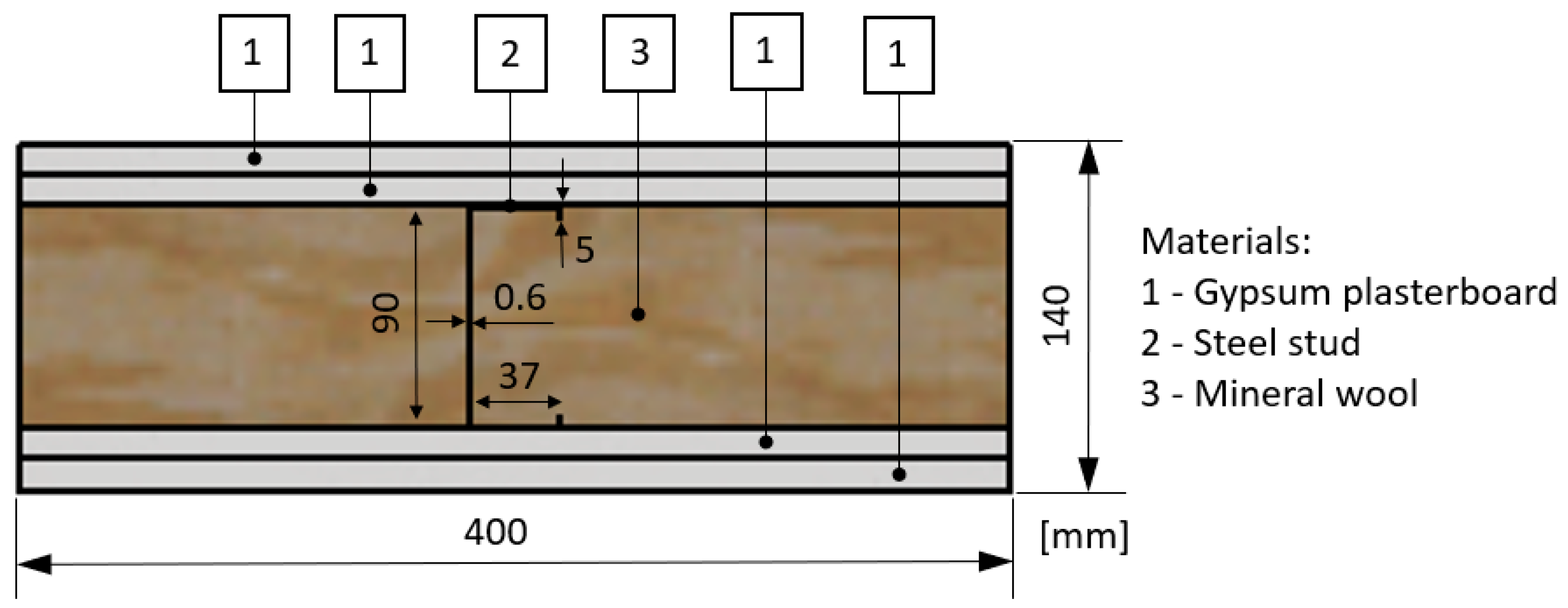
2.1. Description of LSF Partitions
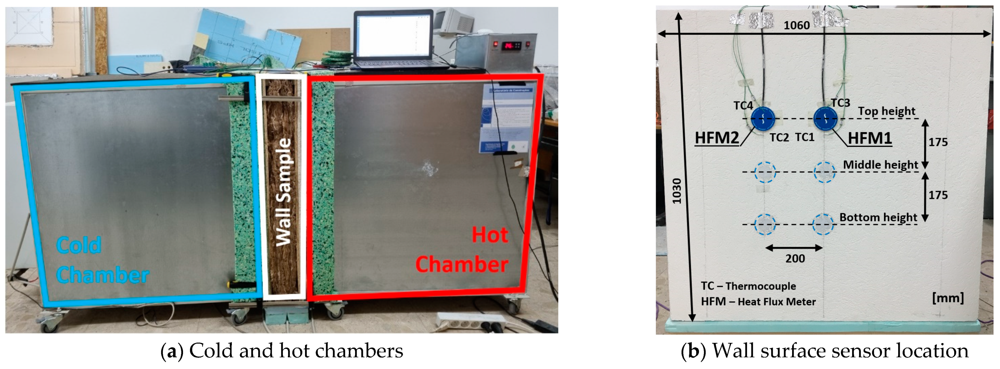
2.2. Lab Measurements
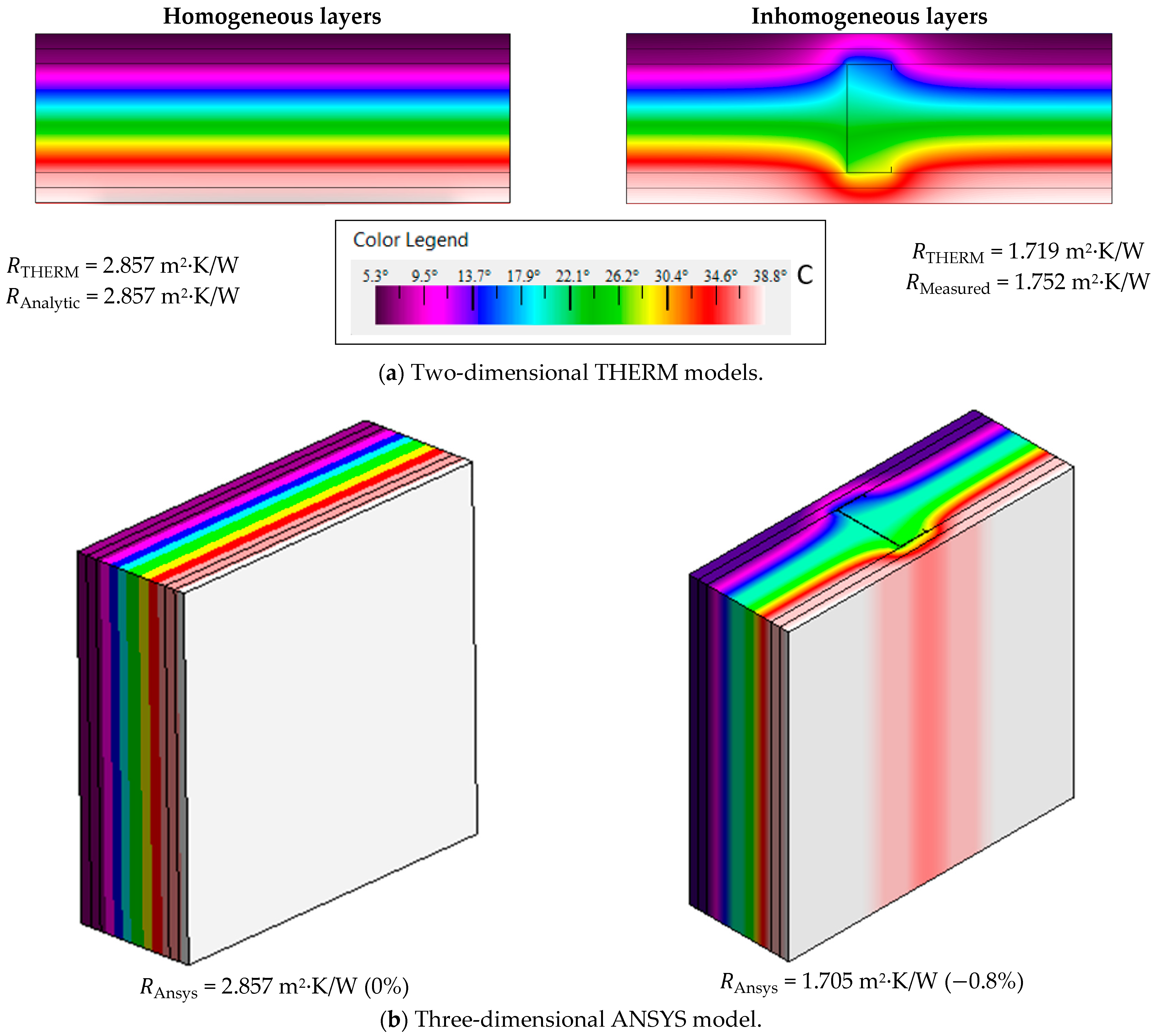
2.3. Numerical Simulations
3. Results and Discussion
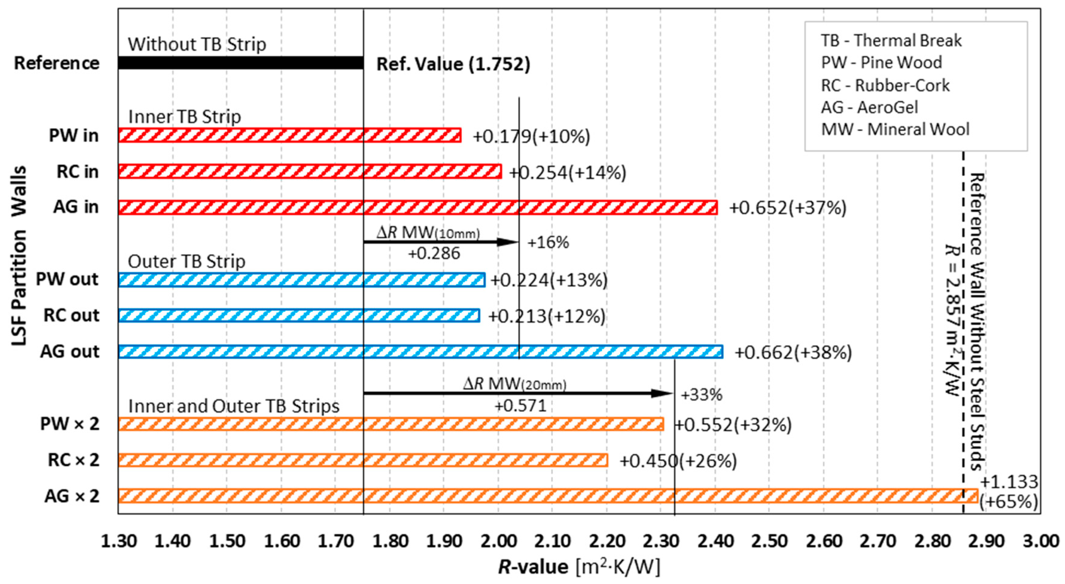
3.1. Conductive Thermal Resistances
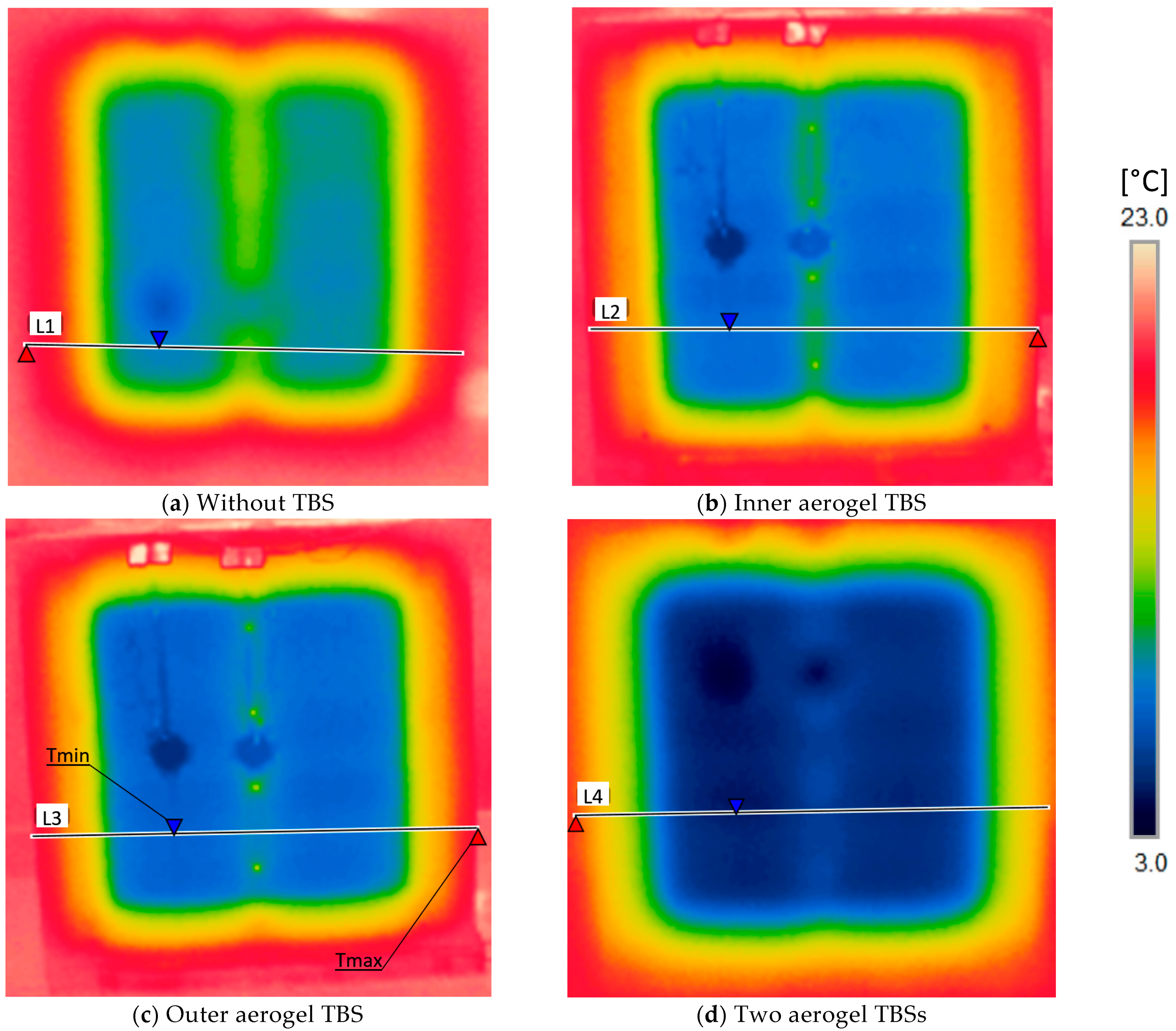
3.2. Thermographic Images
3.3. Heat Flux Predictions
4. Conclusions
- A very good agreement between the R-value measurements and the numerical simulation predictions was achieved, having differences smaller than ±2%.
- The thermal performance was quite analogous when a single TBS was utilized on outer or inner steel stud flanges, given the LSF wall symmetry.
- The use of TBSs on both metallic stud flanges significantly enhances the thermal resistance, when compared to the use of only one TBS and without any TBS.
- The best thermal performance was achieved by the aerogel TBS material, given their very reduced thermal conductivity, when compared with the remaining materials.
- The use of the high-performance aerogel TBSs on both steel profile flanges was the unique configuration able to fully mitigate the thermal bridge effect due to the steel frame, reaching the thermal resistance provided by the reference wall having homogeneous layers, i.e., without steel profiles.
- The bio-based pine wood TBS exhibited a better thermal performance when compared to the recycled rubber–cork composite TBS, for some wall configurations (outer and two TBSs).
- The TBSs’ thickness also has a significant influence on the wall thermal resistance, not only because it mitigates the local thermal bridge effect on the steel stud, but also given the mineral wool expansion, which increases the wall cavity thermal resistance (between metallic studs).
Author Contributions
Funding

Acknowledgments
Conflicts of Interest
References
- EU. Directive (EU) 2018/844 of the European parliament and of the council on the energy performance of buildings and on energy efficiency. Off. J. Eur. Union 2018, 156, 75–91. [Google Scholar]
- Zhan, Q.; Xiao, Y.; Musso, F.; Zhang, L. Assessing the hygrothermal performance of typical lightweight steel-framed wall assemblies in hot-humid climate regions by monitoring and numerical analysis. Build. Environ. 2021, 188, 107512. [Google Scholar] [CrossRef]
- Soares, N.; Santos, P.; Gervásio, H.; Costa, J.J.; Simões da Silva, L. Energy efficiency and thermal performance of lightweight steel-framed (LSF) construction: A review. Renew. Sustain. Energy Rev. 2017, 78, 194–209. [Google Scholar] [CrossRef]
- Perera, D.; Upasiri, I.; Poologanathan, K.; Gatheeshgar, P.; Sherlock, P.; Hewavitharana, T.; Suntharalingam, T. Energy performance of fire rated LSF walls under UK climate conditions. J. Build. Eng. 2021, 44, 03293. [Google Scholar] [CrossRef]
- Ribeiro, T.; Santos, P.; Mateus, D. Performance of Thermal Break Strips in Lightweight Steel Framed Walls. In Proceedings of the 1st International Conference on Water Energy Food and Sustainability (ICoWEFS 2021), Leiria, Portugal, 10–12 May 2021; Springer International Publishing: Cham, Switzerland, 2021; pp. 382–389. [Google Scholar] [CrossRef]
- Santos, P. Chapter 3-Energy Efficiency of Lightweight Steel-Framed Buildings. In Energy Efficient Buildings; Yap, E.H., Ed.; InTech: London, UK, 2017; pp. 35–60. [Google Scholar] [CrossRef]
- Silvestre, N.; Pires, J.; Santos, A. Manual de Conceção de Estruturas e Edificios em LSF-Light Steel Framing, 1a; CMM: Coimbra, Portugal, 2013. [Google Scholar]
- Roque, E.; Santos, P.; Pereira, A. Thermal and sound insulation of lightweight steel-framed façade walls. Sci. Technol. Built Environ. 2019, 25, 156–176. [Google Scholar] [CrossRef]
- Wang, C.; Mynors, D. Acoustic performance of cold-formed steel buildings. In Recent Trends in Cold-Formed Steel Construction; Woodhead Publishing: Sawston, UK, 2016; pp. 173–182. [Google Scholar] [CrossRef]
- Roque, E.; Santos, P. The effectiveness of thermal insulation in lightweight steel-framedwalls with respect to its position. Buildings 2017, 7, 13. [Google Scholar] [CrossRef]
- Atsonios, I.A.; Mandilaras, I.D.; Kontogeorgos, D.A.; Founti, M.A. Two new methods for the in-situ measurement of the overall thermal transmittance of cold frame lightweight steel-framed walls. Energy Build. 2018, 170, 183–194. [Google Scholar] [CrossRef]
- Santos, P.; Lemes, G.; Mateus, D. Thermal transmittance of internal partition and external facade LSF walls: A parametric study. Energies 2019, 12, 2671. [Google Scholar] [CrossRef]
- Santos, P.; Simões da Silva, L.; Ungureanu, V. Energy Efficiency of Light-Weight Steel-Framed Buildings, 1st ed.; Technical Committee 14-Sustainability & Eco-Efficiency of Steel Construction; European Convention for Constructional Steelwork (ECCS): Brussels, Belgium, 2012; ISBN 978-92-9147-105-8. [Google Scholar]
- Santos, P.; Gonçalves, M.; Martins, C.; Soares, N.; Costa, J.J. Thermal transmittance of lightweight steel framed walls: Experimental versus numerical and analytical approaches. J. Build. Eng. 2019, 25, 100776. [Google Scholar] [CrossRef]
- Gorgolewski, M. Developing a simplified method of calculating U-values in light steel framing. Build. Environ. 2007, 42, 230–236. [Google Scholar] [CrossRef]
- Kosny, J.; Christian, J.E.; Barbour, J.; Goodrow, J. Thermal Performance of Steel Framed Walls; ORNL Report; Oak Ridge National Laboratory: Oak Ridge, TN, USA, 1994. [Google Scholar]
- ASHRAE. Handbook of Fundamentals, SI ed.; ASHRAE-American Society of Heating, Refrigerating and Air-Conditioning Engineers: Atlanta, GA, USA, 2017. [Google Scholar]
- Muzzi, T.A.; Souza, H.A.; Gomes, A.P. Heat transfer analysis of the vertical closing system in light steel framing using the isothermal planes method and finite element method. REM-Int. Eng. J. 2021, 74, 425–431. [Google Scholar] [CrossRef]
- Martins, C.; Santos, P.; Simoesdasilva, L. Lightweight steel-framed thermal bridges mitigation strategies: A parametric study. J. Build. Phys. 2016, 39, 342–372. [Google Scholar] [CrossRef]
- Santos, P.; Martins, C.; Simoesdasilva, L.; Bragança, L. Thermal performance of lightweight steel framed wall: The importance of flanking thermal losses. J. Build. Phys. 2014, 38, 81–98. [Google Scholar] [CrossRef]
- Manzan, M.; De Zorzi, E.Z.; Lorenzi, W. Numerical simulation and sensitivity analysis of a steel framed internal insulation system. Energy Build. 2018, 158, 1703–1710. [Google Scholar] [CrossRef]
- ISO 10211; Thermal Bridges in Building Construction-Heat Flows and Surface Temperatures-Detailed Calculations. ISO-International Organization for Standardization: Geneva, Switzerland, 2017.
- Soares, N.; Martins, C.; Gonçalves, M.; Santos, P.; da Silva, L.S.; Costa, J.J. Laboratory and in-situ non-destructive methods to evaluate the thermal transmittance and behavior of walls, windows, and construction elements with innovative materials: A review. Energy Build. 2019, 182, 88–110. [Google Scholar] [CrossRef]
- Gori, V.; Marincioni, V.; Biddulph, P.; Elwell, C.A. Inferring the thermal resistance and effective thermal mass distribution of a wall from in situ measurements to characterise heat transfer at both the interior and exterior surfaces. Energy Build. 2017, 135, 398–409. [Google Scholar] [CrossRef]
- Santos, P.; Poologanathan, K. The importance of stud flanges size and shape on the thermal performance of lightweight steel framed walls. Sustainability 2021, 13, 3970. [Google Scholar] [CrossRef]
- ThermaChannel. Website ‘ThermaChannel-Energy-Efficient Steel Framing’. 2018. Available online: www.thermachannel.com (accessed on 5 February 2019).
- Lupan, L.M.; Manea, D.L.; Moga, L.M. Improving Thermal Performance of the Wall Panels Using Slotted Steel Stud Framing. Procedia Technol. 2016, 22, 351–357. [Google Scholar] [CrossRef]
- Váradi, J.; Toth, E. Thermal Improvement of Lightweight Façades containing Slotted Steel Girders. In Proceedings of the Twelfth International Conference on Civil, Structural and Environmental Engineering Computing, Funchal, Portugal, 1–4 September 2009. [Google Scholar]
- Santos, P.; Mateus, D. Experimental assessment of thermal break strips performance in load-bearing and non-load-bearing LSF walls. J. Build. Eng. 2020, 32, 101693. [Google Scholar] [CrossRef]
- Kapoor, D.R.; Peterman, K.D. Quantification and prediction of the thermal performance of cold-formed steel wall assemblies. Structures 2021, 30, 305–315. [Google Scholar] [CrossRef]
- Kempton, L.; Kokogiannakis, G.; Green, A.; Cooper, P. Evaluation of thermal bridging mitigation techniques and impact of calculation methods for lightweight steel frame external wall systems. J. Build. Eng. 2021, 43, 102893. [Google Scholar] [CrossRef]
- Kosny, J.; Christian, J.E. Thermal evaluation of several configurations of insulation and structural materials for some metal stud walls. Energy Build. 1995, 22, 157–163. [Google Scholar] [CrossRef]
- Santos, P.; Ribeiro, T. Thermal performance improvement of double-pane lightweight steel framed walls using thermal break strips and reflective foils. Energies 2021, 14, 6927. [Google Scholar] [CrossRef]
- Bruno, R.; Bevilacqua, P.; Ferraro, V.; Arcuri, N. Reflective thermal insulation in non-ventilated air-gaps: Experimental and theoretical evaluations on the global heat transfer coefficient. Energy Build. 2021, 236, 110769. [Google Scholar] [CrossRef]
- Jelle, B.P.; Kalnæs, S.E.; Gao, T. Low-emissivity materials for building applications: A state-of-the-art review and future research perspectives. Energy Build. 2015, 96, 329–356. [Google Scholar] [CrossRef]
- Fantucci, S.; Serra, V. Investigating the performance of reflective insulation and low emissivity paints for the energy retrofit of roof attics. Energy Build. 2019, 182, 300–310. [Google Scholar] [CrossRef]
- ISO 9869-1; Part 1: Heat Flow Meter Method. Thermal Insulation-Building Elements-In-Situ Measurement of Thermal Resistance and Thermal Transmittance. ISO-International Organization for Standardization: Geneva, Switzerland, 2014.
- THERM. Software Version 7.6.1. Lawrence Berkeley National Laboratory: Berkeley, CA, USA. 2017. Available online: https://windows.lbl.gov/software/therm (accessed on 14 February 2019).
- ANSYS Workbench. Software Version 19.1. ANSYS, Inc.: Canonsburg, PA, USA. 2018. Available online: www.ansys.com/products/ (accessed on 8 June 2020).
- Gyptec, I. Technical Sheet: Standard Gypsum Plasterboard. 2022. Available online: https://www.gyptec.eu/documentos/Ficha_Tecnica_Gyptec_A.pdf (accessed on 10 February 2022).
- Volcalis. Technical Sheet: Alpha Mineral Wool. 2022. Available online: https://www.volcalis.pt/categoria_file_docs/fichatecnica_volcalis_alpharollo-386.pdf (accessed on 10 February 2022).
- Santos, C.; Matias, L. ITE50-Coeficientes de Transmissão Térmica de Elementos da Envolvente dos Edifícios; LNEC-Laboratório Nacional de Engenharia Civil: Lisboa, Portugal, 2006. (In Portuguese) [Google Scholar]
- MS-R0 Test Report. Test Report Ref. 5015 PE 1977/08-Determination of Thermal Conductivity (Acousticork MS-R0). In Departamento de Engenharia Têxtil; Universidade do Minho: Braga, Portugal, 2008.
- Proctor Group. Spacetherm® CBS Specification. 2018. Available online: https://www.proctorgroup.com/assets/PerformanceSpecs/SpacethermCBSPerformanceSpecification.pdf (accessed on 10 February 2022).
- ISO 6946; Building Components and Building Elements—Thermal Resistance and Thermal Transmittance—Calculation Methods. ISO-International Organization for Standardization: Geneva, Switzerland, 2017.


| Constitutive Materials | d [mm] | λ [W/(m∙K)] | Ref. |
|---|---|---|---|
| Gypsum Plaster Board (2 × 12.5 mm) | 25 | 0.175 | [40] |
| Mineral Wool (MW) | 90 | 0.035 | [41] |
| Steel Studs (C90 × 37 × 5 × 0.6 mm) | --- | 50.000 | [42] |
| Gypsum Plaster Board (2 × 12.5 mm) | 25 | 0.175 | [40] |
| Global Thickness | 140 | --- | --- |
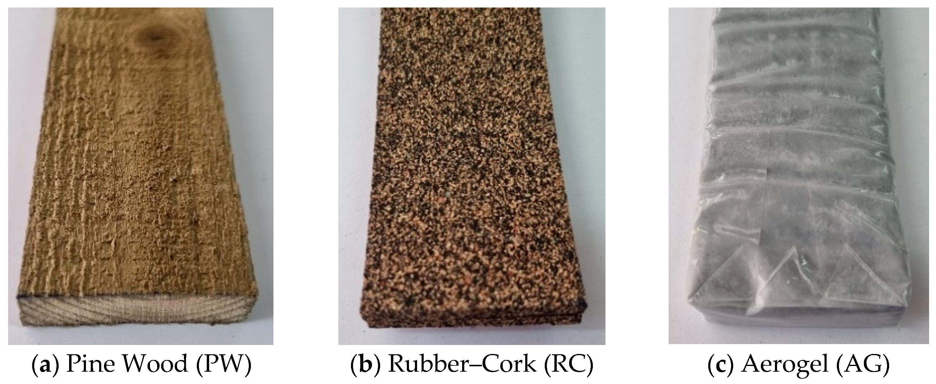
| Materials (Abbreviation) | λ [mW/(m∙K)] | Ref. |
|---|---|---|
| Pine Wood (PW) | 130 | [42] |
| Rubber and Cork composite (RC) | 88 | [43] |
| Aerogel (AG) | 15 | [44] |
| Wall Code Wall Description | R-Value | Difference | ||
|---|---|---|---|---|
| THERM | Measured | Absolute | Percentage | |
| [(m2∙K)/W] | [(m2∙K)/W] | [(m2∙K)/W] | [%] | |
| Ref. Reference LSF Partition Wall | 1.719 | 1.752 | +0.033 | +2% |
| PWin Inner Pine Wood TBS | 1.976 | 1.931 | −0.045 | −2% |
| RCin Inner Rubber–Cork TBS | 2.006 | 2.006 | +0.000 | 0% |
| AGin Inner Aerogel TBS | 2.359 | 2.404 | +0.045 | +2% |
| PWout Outer Pine Wood TBS | 1.981 | 1.976 | −0.005 | 0% |
| RCout Outer Rubber–Cork TBS | 1.975 | 1.965 | −0.010 | −1% |
| AGout Outer Aerogel TBS | 2.358 | 2.414 | +0.056 | +2% |
| PWx2 Double Pine Wood TBSs | 2.254 | 2.304 | +0.050 | +2% |
| RCx2 Double Rubber–Cork TBSs | 2.236 | 2.202 | −0.034 | −2% |
| AGx2 Double Aerogel TBSs | 2.892 | 2.885 | −0.007 | 0% |
Publisher’s Note: MDPI stays neutral with regard to jurisdictional claims in published maps and institutional affiliations. |
© 2022 by the authors. Licensee MDPI, Basel, Switzerland. This article is an open access article distributed under the terms and conditions of the Creative Commons Attribution (CC BY) license (https://creativecommons.org/licenses/by/4.0/).
Share and Cite
Santos, P.; Abrantes, D.; Lopes, P.; Mateus, D. Experimental and Numerical Performance Evaluation of Bio-Based and Recycled Thermal Break Strips in LSF Partition Walls. Buildings 2022, 12, 1237. https://doi.org/10.3390/buildings12081237
Santos P, Abrantes D, Lopes P, Mateus D. Experimental and Numerical Performance Evaluation of Bio-Based and Recycled Thermal Break Strips in LSF Partition Walls. Buildings. 2022; 12(8):1237. https://doi.org/10.3390/buildings12081237
Chicago/Turabian StyleSantos, Paulo, David Abrantes, Paulo Lopes, and Diogo Mateus. 2022. "Experimental and Numerical Performance Evaluation of Bio-Based and Recycled Thermal Break Strips in LSF Partition Walls" Buildings 12, no. 8: 1237. https://doi.org/10.3390/buildings12081237
APA StyleSantos, P., Abrantes, D., Lopes, P., & Mateus, D. (2022). Experimental and Numerical Performance Evaluation of Bio-Based and Recycled Thermal Break Strips in LSF Partition Walls. Buildings, 12(8), 1237. https://doi.org/10.3390/buildings12081237