Article

FEM-Based Evaluation of the Point Thermal Transmittance of Various Types of Ventilated Façade Cladding Fastening Systems

Department of Construction Materials and Technologies, Faculty of Civil Engineering, Budapest University of Technology and Economics, Műegyetem rkp. 3, 1111 Budapest, Hungary
*
Author to whom correspondence should be addressed.
Buildings 2022, 12(8), 1153; https://doi.org/10.3390/buildings12081153
Submission received: 10 July 2022 / Revised: 28 July 2022 / Accepted: 29 July 2022 / Published: 2 August 2022

Abstract

:
The prevalence of ventilated façade systems is not only due to their aesthetic properties but also due to the fact they provide mechanical and acoustic protection for the façade and reduce the energy demand of the building. However, it is essential to mention that the point thermal bridges of the fastening system with brackets and anchors are often neglected during simplified energy performance calculations and practical design tasks. The reason practitioners do not consider the brackets in the calculation is the lack of standards for the simplified calculation of point thermal transmittances, or there being no comprehensive, manufacturer-independent thermal bridge catalogue available. This study aims to evaluate the point thermal transmittances created by the brackets and anchors of the ventilated façade claddings by using 3D numerical thermal modelling. A broad point thermal bridge catalogue was created, considering multiple factors of the ventilated facades. The FEM-based results show that thermal breaks/isolators could reduce the point thermal transmittances by only 2 to 28%, depending on the material of the brackets and the isolators. The brackets’ material and geometrical properties/parameters could cause up to 70% of difference between corrected and uncorrected thermal transmittance values, as well as significant differences between the results if the brackets were applied to different kinds of masonry walls or reinforced concrete walls.

1. Introduction

The ventilated façade system is a popular cladding system to decrease energy consumption in most recently built office buildings or buildings under renovation. Through its construction, it protects and keeps the walls and the thermal insulation of the building dry, as well as reducing the heat transfer of the walls, thus ensuring a longer life for the installation. Since the cladding is anchored to the wall with brackets, cracks in the cladding caused by building movement can be avoided. Due to the “mass-spring-mass” principle, it has advantageous sound protection properties and is made with dry technology, so it can be constructed all year round and requires little maintenance [1,2]. The most crucial measure of the building envelope in energy performance calculations is its thermal transmittance, which must be corrected due to various inhomogeneities and thermal bridges. In the case of ventilated façade claddings, the point thermal bridges which need to be considered within the thermal transmittance of the building envelope are caused by the elements of the fastening system, namely the brackets that punctuate the thermal insulation and the anchors and dowels holding the brackets.
As mentioned above, one of the first efforts to consider the heat losses caused by the fixings was published in 1984 [3]. Later, in 2006, BREE published a guideline [4] for calculating U-values, including the effect of ventilated façade claddings as a non-derivative recommendation, in case it is not possible to determine the thermal transmittance by numerical modelling. The standards nowadays do not provide any current guidance to account for the thermal effects of fasteners except for finite element simulations or empirical modelling, which is why several professionals have tried to develop thermal bridge catalogues [5] and simplified calculation methods [6].
Analysing the available scientific literature on the topic, most of the studied literature agrees that the neglect of point thermal bridges caused by fasteners can result in a significant difference of up to 5 to 30% in the calculation of heat losses in the studied building. A good example is a study by García et al. [7], which examined the results calculated based on empirical, numerical and experimental methods in a real environment, in different façade configurations. The research confirmed that the results obtained with the simplified method differ significantly from the experimental hotbox measurement results, especially when using high thermal conductivity brackets. A study by Levinskytė et al. [8] concluded that the use of the simplified method could be misleading when looking at the results since while in the case of brackets with low thermal conductivity, we get the results calculated from the numerical simulation with a difference of only 3.6%, in the case of brackets with higher thermal conductivity this difference is of 70 to 130.4%. They also examined the difference between the results of empirical and numerical calculation methods. They said that in all cases, the empirical calculation method according to ISO 6946 [9] showed much higher thermal transmittance values than the method according to ISO 10211 [10] using 3D simulation software.
Most of the previously published research has examined the effect of stainless steel, steel and aluminium brackets [8,11] on point thermal transmittances, but in [12], they also dealt with perforated brackets. Glass fibre-reinforced brackets were also examined [8]. A catalogue for carbon steel and “thermo” brackets made of polymer composite material was also created [13]. The studies mentioned above showed that choosing a bracket with the appropriate thermal conductivity, such as stainless steel or steel composite, can significantly reduce the U-values calculated for the structure by up to 40%. In the case of aluminium brackets [14], the tests have shown that an increase in thermal conductivity of the material of the supporting layer and the thickness of the thermal insulation layer may increase the U-value of the entire wall up to 35% as a result of the effect of point thermal bridge. Hilti [15], one of the largest European manufacturers of brackets, also used numerical models to investigate how thermal insulation properties and brackets affected the value of point thermal transmittance and created a thermal bridge catalogue for their own fastening systems. Another main aspect of the investigation in most of the research is the effect of thermal insulation properties and the wall on point thermal transmittance. They mainly examined local materials typical of the country of the study. Thus, the primary materials of the walls are concrete, reinforced concrete and masonry wall, but also cellular concrete [12], red clay brick [11] and silicate block [16] were examined. Theodosiou et al. [17,18,19] examined the effects of different materials and geometric properties on the point thermal transmittance of brackets. They concluded that neither the thermal insulation nor the thermal breaks could effectively reduce the effects of the point thermal bridges generated by the brackets. In most scientific literature, only the brackets were examined, and their anchoring and dowels were neglected. However, in [18], steel, plastic and chemical anchoring were examined, respectively, but only steel and chemical anchors were analysed in comparison. In [16], 3D numerical simulations were used to create temperature distribution diagrams for walls and thermal insulation with different materials and thermal conductivities. They pointed out the problems of thermal bridges caused by brackets and dowels. To reduce the point thermal bridges caused by the fastenings, Ingeli et al. [20] patented the use of plastic-coated anchors, which can effectively reduce the effect of point thermal bridges, and thus the heat loss of the buildings. However, most studies only deal with the extent to which parameters influence the value of the thermal transmittance but only came to the evaluation of the data, and no simplified calculation method was developed. Šadauskienė et al. [21] have tried to develop a simplified calculation method. However, the system of equations determining the point thermal transmittance they create applies only to the modelled ranges and contains non-independent parameters.
The current research aims to create a comprehensive and manufacturer-independent thermal bridge catalogue that can be used internationally to help practitioners and academics calculate ventilated façades. Firstly, the possible values of the different parameters needed for modelling were collected. Then, a total of 60 different parametric geometric models were created to be able to handle all significant cases. The point thermal transmittances of the ventilated façades on different walls using different brackets, thermal breaks, anchors and dowels were modelled and evaluated. The values were summarised in a thermal bridge catalogue, and a simplified method was developed based on the current ISO standards.

2. Materials and Methods

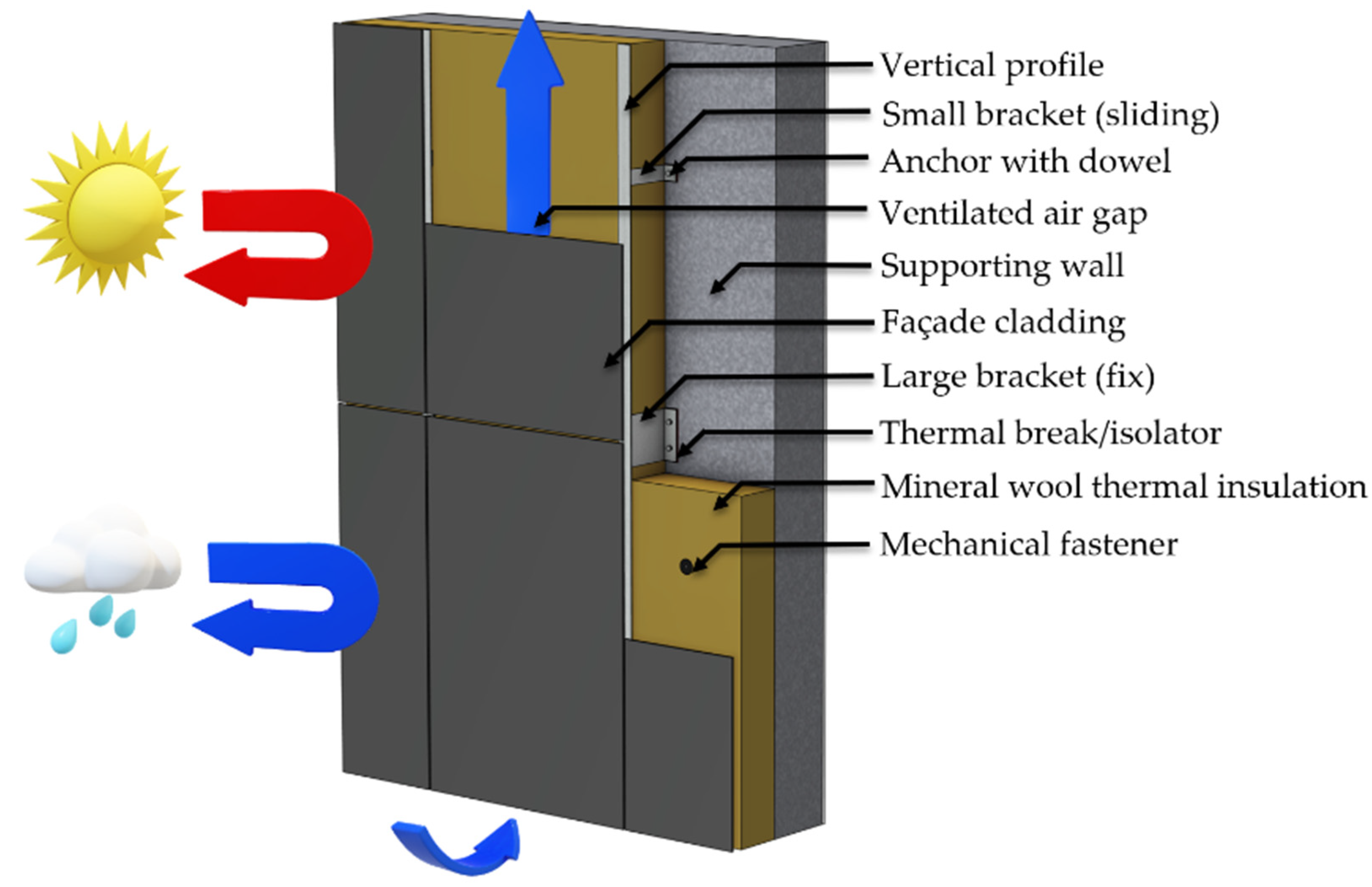
2.1. Construction of the Ventilated Façade System

The general structure of ventilated façade cladding systems is shown in Figure 1. The material of the cladding systems changes on an extensive scale; there are glazed ceramics, metal sheets, fibre cement, stone slabs, composites and plastic boards. The outer crust/layer operates on a “parasol-umbrella” principle (see Figure 1). It protects the wall and the thermal insulation against solar radiation like a parasol. It protects against precipitation like an umbrella, hence the common term “rainscreen cladding” [22]. The outer layer also includes protection against external mechanical effects and meteorological loads, such as wind. The next layer is the open ventilation air gap, in which the air flows from the bottom upwards due to the “chimney effect”, so that in winter, the flowing air transports the diffused moisture from the interiors [23]. At the same time, in summer, it acts as a heat shield, thus improving the thermal insulation of the façade. To ensure this effect and the ventilation, the recommended thickness is between 3 and 5 cm considering the moisture removal capacity of the ventilated air channel [24], but this also depends on, among other things, ambient conditions, type of materials used, the height of the building and the width of the façade wall [25].
Choosing the appropriate air layer thickness is also important and cannot be neglected, as here, we can compensate for the differences in dimensional tolerances between the retaining wall and cladding boards. It is important to note that due to the chimney effect, great attention must be paid to fire protection, as fire can spread much more quickly in these ventilated air gaps due to the air flowing upwards [26]. Hence, it is crucial to choose non-combustible thermal insulation. Behind the intensively ventilated air layer is the thermal insulation; in most cases, mineral wool. It is recommended to select a higher density version so that the air in the thermal insulation remains calm and does not start flowing, thus impairing the thermal insulation effect [27].

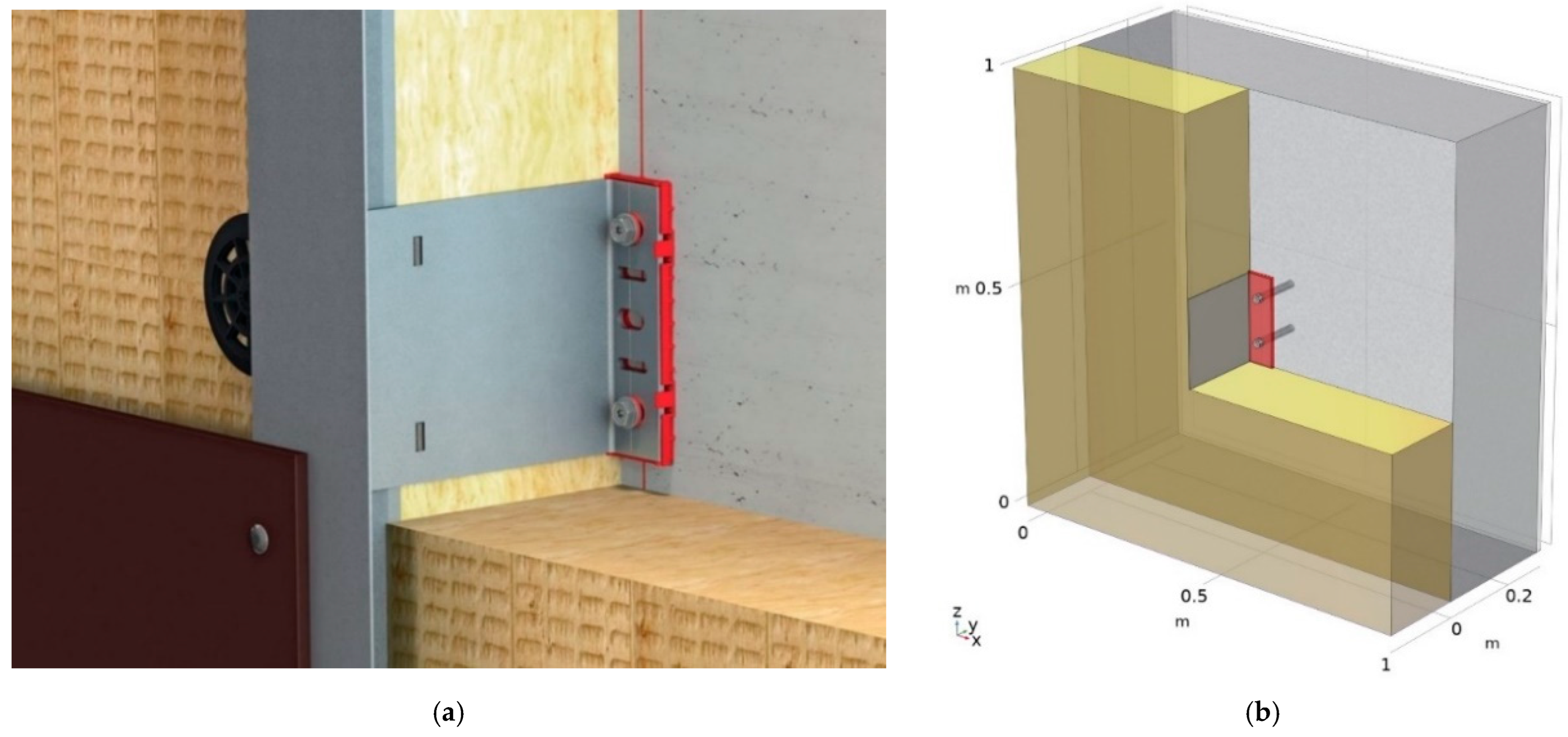
2.2. Parameters and Geometry

The first step to being able to model the ventilated façade claddings’ fastening systems was to collect their elements and determine their geometrical and thermal properties. It is important to note that during the modelling, the effect of the exterior cladding and the ventilated air layer was neglected. This research investigates the fastening system’s thermal impact penetrating the thermal insulation. Researchers have dealt with air gaps and the experimental and numerical modelling of the air flowing in the air gap before [28,29,30,31]; however, the thermal effects of the support brackets are typically neglected in these studies. In this current study, we focus on the effects of the fastening systems. ISO 6946 [9] states that if an air layer is intensively ventilated, it can be excluded from the thermal calculations with all the other external layers. Many previously mentioned studies excluded the cladding and the ventilated air layer from their study. The above-mentioned standard also states that the heat transfer coefficient should be applied on the surface of the thermal insulation, and it shall not be corrected due to the brackets sticking out since all the brackets have higher than 2.5 W/(m × K) thermal conductivity.
Therefore, during the modelling, it is sufficient to consider elements in direct contact with fasteners such as the wall, plaster/mortar, thermal insulation, brackets and dowels. Since more than 20 independent parameters were required to build the geometric model, to reduce the number of combinations, the lower and upper limits and, in some cases, an intermediate value, were specified as input parameters. Even after collecting and reducing the parameters, nearly 100,000 possible combinations would have been impossible to handle; thus, the geometry had to be split into parts. A distinction was made between the material of the wall and the other separations along the presence of the thermal breaks/isolators, the wall and the thermal insulation thicknesses and the number of dowels. This process resulted in creating 60 parameterised geometric models using Comsol Multiphysics finite element numerical modelling software [32], in which the rest of the parameters were controlled by presets. A selected numerical model, including a reinforced concrete (RC) wall, a bracket fixed with two anchors and a thermal break with its simplifications, is shown in Figure 2 compared to a commercially available ventilated façade system containing similar elements.
An example of a parameterised geometric model is shown in Figure 2b. We selected the components and materials for the study to correspond to the most common setup of fastening systems based on [15], and we used top and bottom thermal conductivities to represent the variability of the materials, where it was expected to matter. All models were created to handle 1 m2 of construction to simplify the calculations later and ensure that the multidimensional heat flows can develop during the modelling to their full extent; therefore, the model size does not affect the results. The geometry of the used elements was simplified to be able to be handled and meshed during finite element modelling.
In the modelled scenarios, the following parameters were considered and listed in Table 1. The wall is constructed using masonry or reinforced concrete. Masonry walls were considered with thicknesses between 25 cm and 38 cm, using different thermal conductivities available in Hungary, e.g., 0.07 W/(m × K) to represent a modern thermal insulation-filled masonry block or 0.72 W/(m × K) to include small solid masonry bricks. The RC walls were 15, 20, 25 and 30 cm thick using 2.0 and 2.5 W/(m × K) thermal conductivity. Masonry walls included both 1.5 cm thick internal and 1 cm thick external plaster, while RC walls only had 1.5 cm thick internal plaster since it is considered airtight without external plastering. The thermal insulation was mineral wool with a thickness of 10, 20 or 30 cm, using 0.03 W/(m × K) or 0.04 W/(m × K), the available range of nowadays’ mineral wool thermal conductivity.
The L-shaped supporting brackets were modelled using stainless steel, steel or aluminium. The heights of the brackets were 6 cm for small (fix) and 20 cm for large (sliding) brackets. The base of the brackets was selected as 6 cm for the small bracket and either 6 cm in width or 10 cm for the large bracket. The thickness of the brackets was also parameterised and changed between 4 mm and 8 mm. The length of the brackets was changed accordingly to the thermal insulation’s widths; therefore, 10, 20 and 30 cm were also tested.
Under the brackets, thermal breaks were included in some cases. When thermal breaks were applied, the material was polyamide (PA) or high-density polyethylene (HDPE) with a 5 mm or 20 mm thickness. The brackets were fixed to the wall using stainless steel or steel anchors and PA dowels. To fix the brackets, either 1 anchor for the small or 2 anchors for the large brackets were used in the models, and the fixing depth was also changed between 5 cm and 15 cm, where applicable.

2.3. Numerical Modelling Methodology

Using numerical modelling, we can perform detailed calculations considering the effect of multidimensional heat fluxes [33]. According to [34], in the case of window installations, the effect of point fixings, such as brackets, was compared with 2D and 3D simulations, and the conclusion that in the case of point fixings, 3D numerical simulations should be used. Although there is a method for estimating point thermal transmittance with 2D simulations [35], in our research, we used 3D numerical simulation to handle point thermal transmittances of the fastening systems.
In the frame of this study, Comsol Multiphysics 5.6 software was used to solve the 3D steady-state heat conduction equations to determine the point thermal transmittance considering the effect of point thermal bridges. The calculation methodology, boundary conditions and required accuracy for solids are specified in ISO 10211 [10]. The partial differential equation of steady-state heat conduction is the following:
q = ( λ e f f × T ) = 0
The boundary conditions are set using Equations (2) and (3):
n × q = h c i + ε × 4 × σ × T m , i 3
n × q = h c e + ε × 4 × σ × T m , e 3
where in Equation (2), h c i is the internal convective surface heat transfer coefficient (2.5 W/(m2 × K)), ε is the longwave emissivity of the surface (0.9), σ is the Stefan–Boltzmann constant (5.67 × 10⁻⁸ W/(m2 × K4)) and T m , i is the mean thermodynamic temperature of the internal surface and its surroundings set to 293.15 K according to MSZ 24140 [36]. In Equation (3), h c e = 4 + 4 · v , where v is the wind speed in [m/s] according to [9]. Wind speed was neglected since the cladding protects the surface of the thermal insulation from the wind loads. T m , e is the mean thermodynamic temperature of the external surface and its surroundings in Kelvin set to 268.15 K according to [36].
A mesh independence test on one of the most complex geometrically constructed models (see Figure 2b) was created to select the most suitable finite element mesh density in terms of the accuracy of the results and the run times. This model contained a large bracket with thermal break and was fixed with two anchors. The basis of the error calculation was the value of the point thermal transmittance obtained by applying the existing highest density mesh. As it is possible to set the automatic mesh manually within the Comsol Multiphysics software, a mesh with increased density has been selected for brackets, dowels and thermal breaks, then homogeneously modelled elements such as the wall, thermal insulation and plaster. The meshing and simulations were performed by a workstation including AMD Ryzen Threadripper 2950X CPU (Advanced Micro Devices, Inc., Santa Clara, USA), 128 GB DDR4 RAM (ADATA Technology Co., Ltd., Taiwan), Nvidia Quadro RTX 4000 GPU (NVIDIA Corporate, USA) and 2 TB m.2 SSD (ADATA Technology Co., Ltd., Taiwan). The mesh statistics are summarised in Table 2 for automatic meshing cases.
We also created user-controlled meshing based on automated ones. However, we increased the density of the mesh only for the components of the fastening system, e.g., brackets, thermal breaks, anchors and dowels. Table 3 shows that a user-controlled mesh was performed with a similar error as the automated mesh using finer settings. The software even created the same number of elements and the degree of freedom (DoF). However, this mesh setting resulted in 26 s meshing time instead of 33 s. Since we performed thousands of runs, we preferred the user-controlled meshing to save computational time on the meshing.

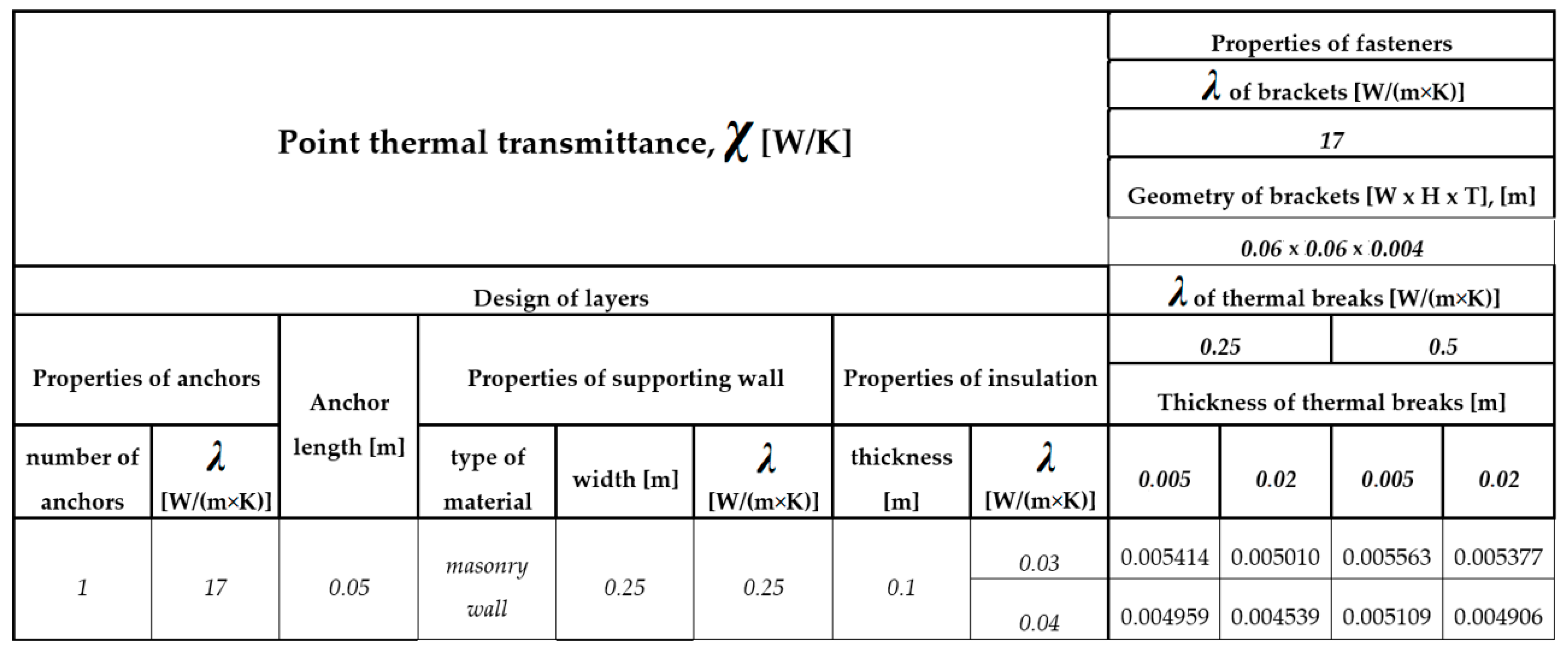
2.4. Calculation of the Point Thermal Transmittances

According to Hungarian TNM decree 7/2006 [33], when examining a wall’s U-value, the effect of the mechanical fastenings must be taken into account based on the equation below during detailed calculations, according to ISO 6946 [9]:
U   [ W m 2 K ] = 1 R s e + i d i λ i + R s i + Δ U f + Δ U g + Δ U r + k n k × χ k
where R s e is the surface resistance of the external surface ((m2 × K)/W), R s i is the resistance of the internal surface ((m2 × K)/W), d i is the thickness of a composing layer (m), λ i is the thermal conductivity of a composing layer (W/(m × K)), Δ U f is the correction factor of the mechanical fasteners (W/(m2 × K)), Δ U g is the correction factor of the joint gaps (W/(m2 × K)), Δ U r is the correction factor of the reverse layered flat roofs (W/(m2 × K)), n k is the number of point thermal bridges (1/m2) and χ k is the point thermal transmittance value (W/K) considered for other kinds of point thermal bridges (e.g., tie-rods, brackets, etc.).
In this research, we investigated the thermal effect of the fastening elements of the façade cladding. Therefore, we dealt with the correction factor for the mechanical fastenings of the brackets. This is important since ISO 6946 Annex F [9] only contains a simplified calculation for Δ U f in the case of cylindrical-shaped mechanical fasteners when fixing the thermal insulation, and it does not deal with point thermal bridges caused by the anchors of the brackets or the L-shaped brackets, which have very different geometries [8].
If we want to take point thermal bridges into account for transmission losses during our calculations other than cylindrical fasteners, then in the absence of a simplified calculation method, we must use numerical modelling, as presented earlier. The behaviour of point thermal bridges can be described by the point thermal transmittance, χ (W/K), which in this case shows how much additional heat flow (W) is caused by a piece of fastening element as a result of a unit temperature difference (1/K).
Its calculation is based on the difference between the heat fluxes calculated for the entire 3D element during the numerical simulation and the heat fluxes obtained by neglecting point thermal bridges:
χ   [ W K ] = L 3 D i = 1 N i U i × A i
where χ is the point thermal transmittance (W/K), L 3 D is the thermal coupling coefficient from the three-dimensional calculation (W/(m2 × K)), U i is the thermal transmittance value calculated by neglecting 3D point thermal bridges (W/(m2 × K)) and A i is the area of the examined element (m2).
Heat losses caused by fasteners can be considered with a correction to the thermal transmittance value. Since the fixing elements repeatedly occur on the façade, their thermal effect can be calculated with a correction factor Δ U (W/(m2 × K)), if we specify how many fixing elements ( n f ) pierce the thermal insulation layer per 1 m2 of the tested surface:
Δ U f = n f × χ  
For simplification, we examined 1 m2 of wall surface during the modelling on which we placed a single bracket. In this case, according to Equation (5), the value of the point thermal transmittance (χ) at the point is the same as the difference between the uncorrected thermal transmittance (U) and point thermal transmittance calculated by the finite element program, which also takes into account the corrections (L3D):
Δ U f = L 3 D U = χ × 1 / m 2  

3. Results and Discussion

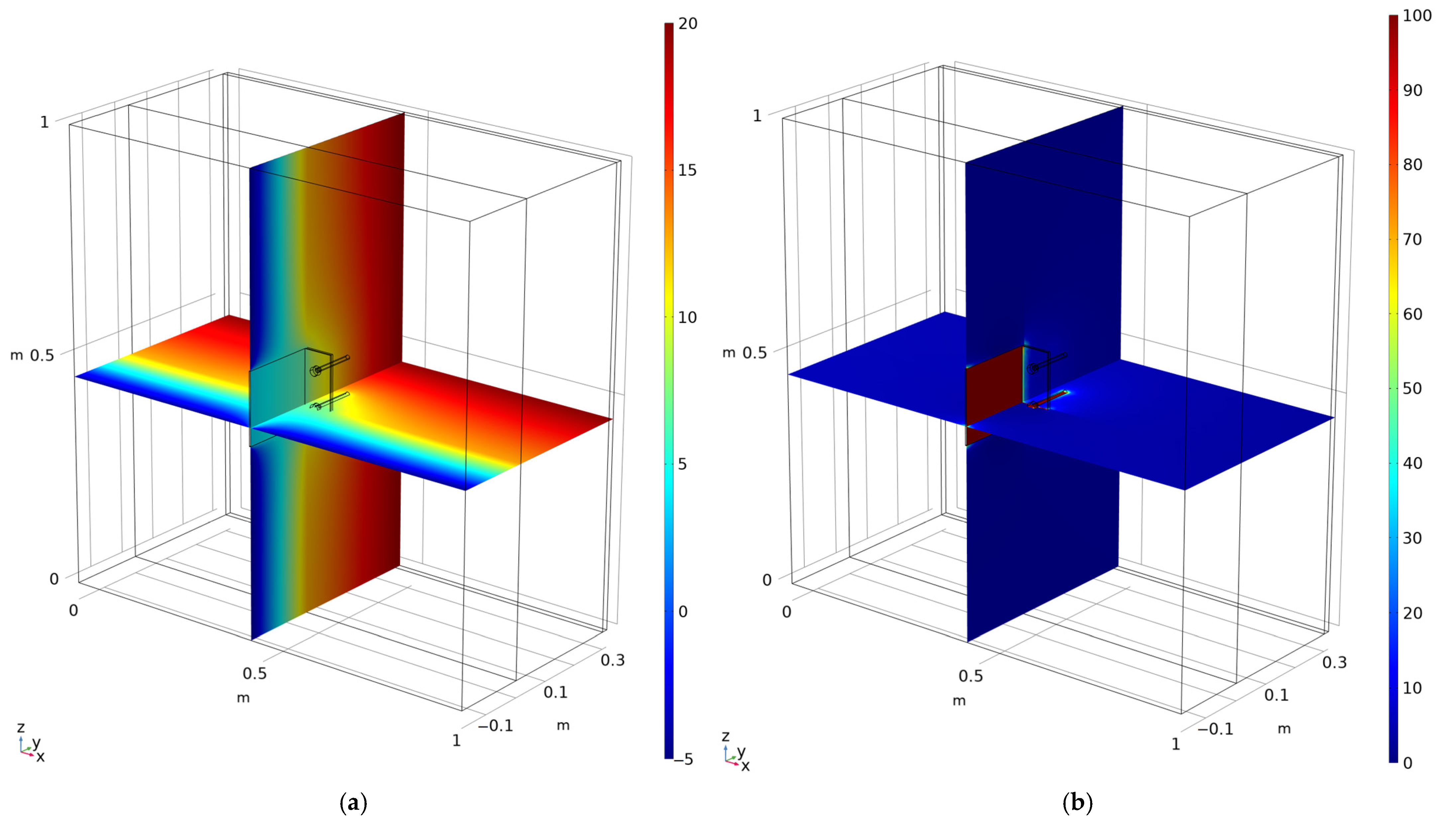
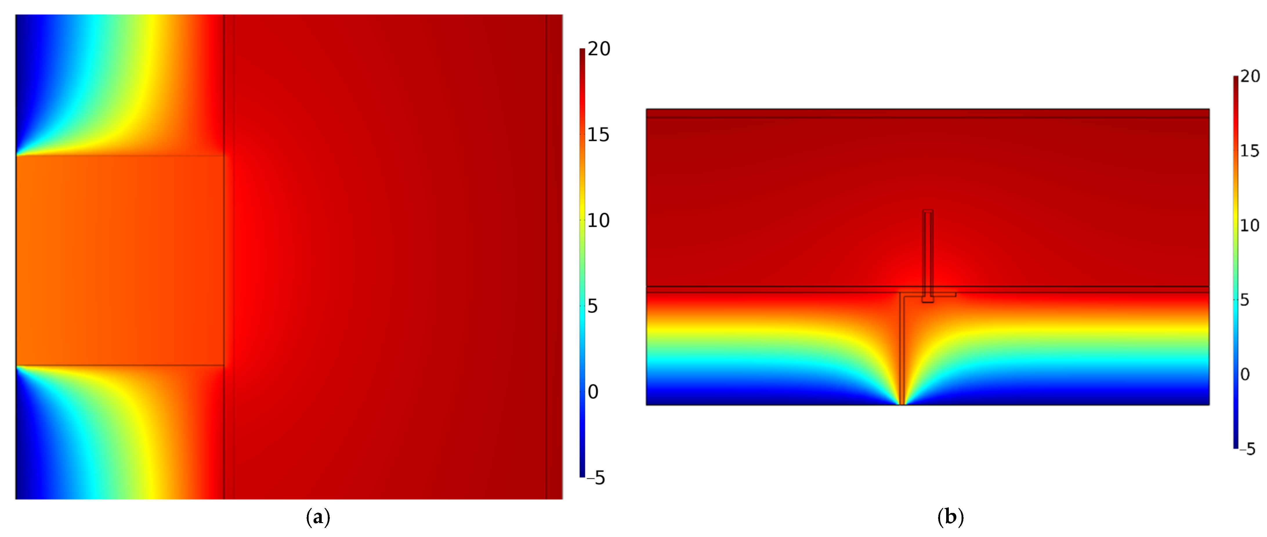
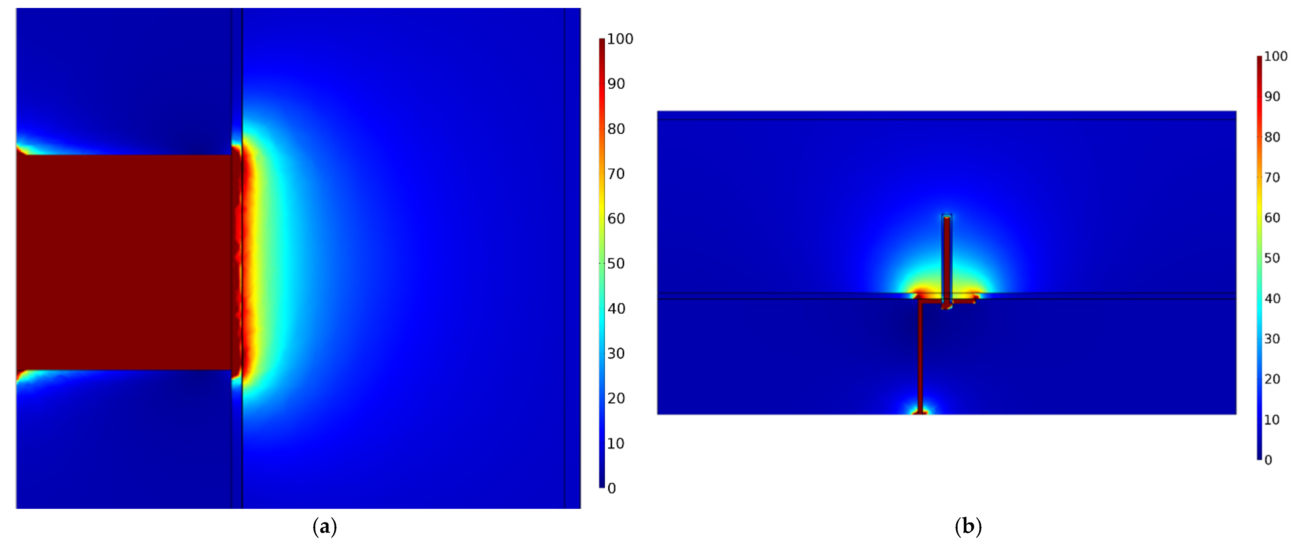
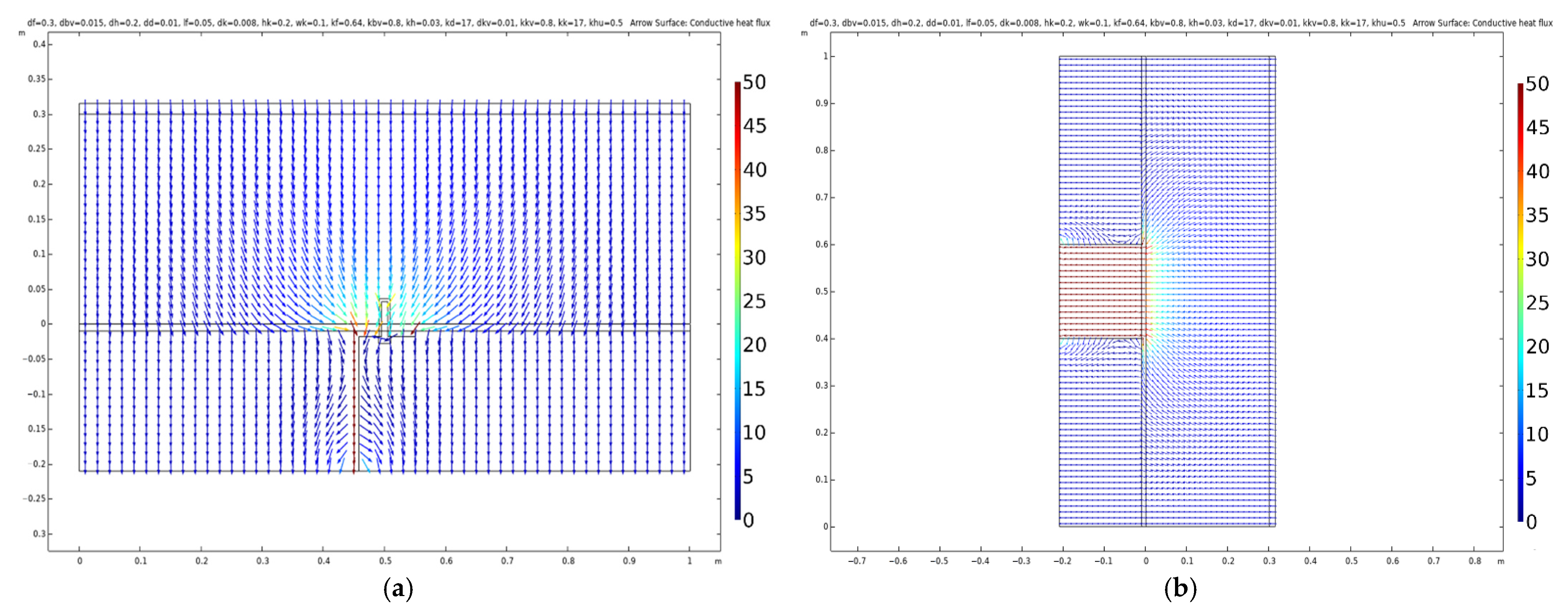
3.1. Visualisation of Results

After the numerical thermal modelling, the temperature distribution and heat flux density can be visualised in 3D. However, the best visibility is provided using 2D sections (see Figure 3).
In Figure 4 and Figure 5, included for illustrational purposes of the evaluation, we selected masonry wall-based geometry to show the possibilities of visualisation. The temperature distribution shows that a bracket causes vast disturbance in the temperature field, especially in the vertical direction, as visible in Figure 4. The brackets are much warmer than the thermal insulation and create thermal bridges in the structure. It is also observable that the brackets, due to their high thermal conductivity, have almost the same temperature along their structure, while in the thermal insulation, the temperature distribution is visible between significantly more extensive temperature ranges. We can also conclude that a single bracket, despite causing temperature disturbance in the thermal insulation, near the base of the bracket and near the anchors and dowels, does not cause any significant changes on the internal surface. Therefore, no condensation risk can occur on the internal surface due to the applying of brackets to fix ventilated façades. This conclusion correlates with Arregi et al. [37]. Their study used different types of brackets made from stainless steel. They said that even 40 mm of thermal insulation is enough to raise the internal surface temperature above the dew point temperature to avoid mould growth. We extend this conclusion by claiming that one can even use aluminium brackets without thermal breaks. The internal temperature will not be significantly affected when using walls with 10–30 cm thermal insulation. Besides examining the temperature distribution, the heat flux density is also visualised in Figure 5. The heat flux density along the bracket is the highest, from which it can be concluded that the heat flows at a significantly higher rate from the structure along the brackets than through the thermal insulation. It is also visible that the surrounding of the base of the bracket also has a higher heat flux density in the masonry wall.
It is also possible to visualise the direction and magnitude of the heat flow vectors shown in Figure 6. Examining several models with different bracket materials, it can be said that the direction of the arrows representing the heat flow vectors is similar and does not change significantly with the bracket material, only the magnitude of the heat flow changes. It can be seen from the figures that in the present case, the heat flows in the horizontal direction from the bracket which can be said to be one-dimensional, and then moving closer, we can speak of 3D heat flows. In the vertical direction, within a distance of about 25–30 cm, the heat flows change from one-dimensional to three-dimensional. The figure in both directions shows that the change in heat flow also affects the thermal insulation layer. Based on these, it can be said that the modelled one square meter area examined during the numerical modelling is sufficient for the study, as there are already one-dimensional heat flows on the boundary surfaces. However, the three-dimensional heat flows around the fixings support the need for 3D numerical simulation. We can also conclude that the ventilated façade claddings’ fastening brackets can be modelled using point thermal bridges since the brackets cause thermal bridges around them and cannot be represented simply by a 2D model.

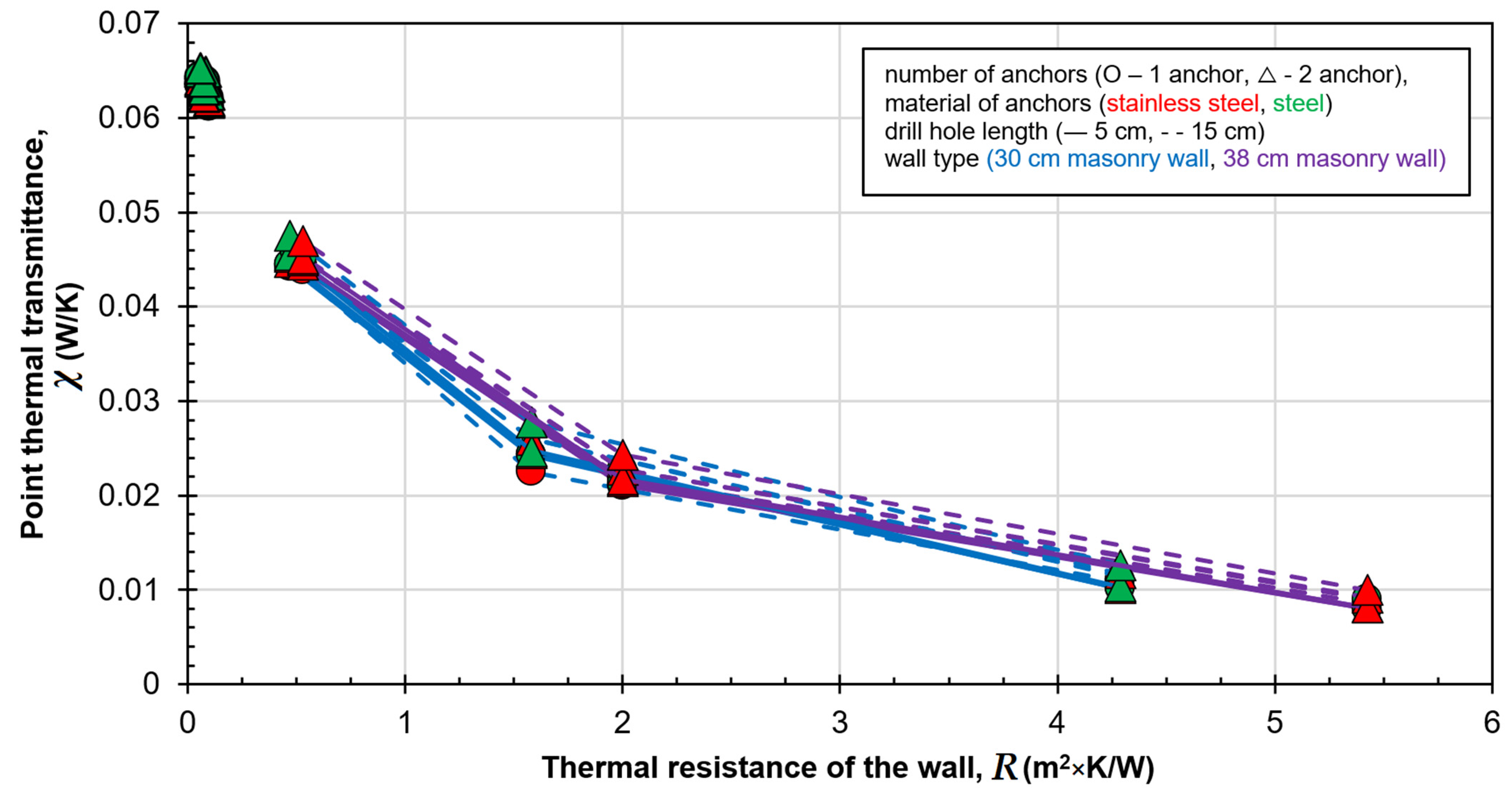
3.2. Effect of the Properties of the Wall

To represent the effect of different wall thicknesses and wall types, we created a figure that shows cases with similar brackets and thermal insulations. In Figure 7, we show cases with 20 cm thermal insulation applied on the walls (0.04 W/(m × K)), and small aluminium brackets with thermal brakes were also considered. Figure 7 shows that as the thermal resistance of the wall (thickness of the wall divided by the thermal conductivity of the wall) increases, the point thermal transmittance decreases significantly, similar to the results of [14], where one of the main findings said the point thermal bridge may decrease the U-value of the entire wall up to 28% regarding the increase of supporting layer thickness and using insulation materials with higher thermal conductivity. We also reached a similar result with [11] in the case of a reinforced concrete wall because due to its high thermal conductivity, we obtain a much higher point thermal transmittance than in masonry walls. This means that the material, the thermal conductivity of the supporting wall, affects the point heat transfer coefficient.
However, Figure 7 also shows that the properties of the anchoring, such as the material of the anchors, the number of anchors and the length of the drill hole, influence the value of the point thermal transmittance, especially when masonry walls were examined. However, anchors have a much smaller influence on the value of the point thermal transmittance than the wall material and may be neglected. This can be explained by the material of the dowels of the anchors because they are made of PA, which essentially acts as a thermal isolator for the anchors. This effect is also examined by [18] including chemical anchoring, and they concluded that this type of anchoring should be chosen whenever possible. Chemical anchoring also creates a thermal isolator for the anchors, similarly to PA. However, in their manuals, fastening system producers usually advise using PA dowels for the anchors when possible since it is much less costly, more known and easier to construct.
Evaluating the reinforced concrete walls with different thicknesses and thermal conductivities, it can be seen that in cases with the same thickness and thermal conductivity but with different anchors, the largest difference between the point thermal transmittance is 3.2%. As the thermal conductivity of the supporting wall increases, the difference between cases with different anchors decreases. In the case of the tested masonry wall with the highest thermal conductivity (0.72 W/(m × K), which belongs to solid ceramic masonry bricks), the difference is also only 3% for the various anchors. However, in the case of masonry walls with low thermal conductivity (0.07 W/(m × K), which belongs to modern, thermal insulation-filled masonry blocks [38]), this difference is of almost 20%.

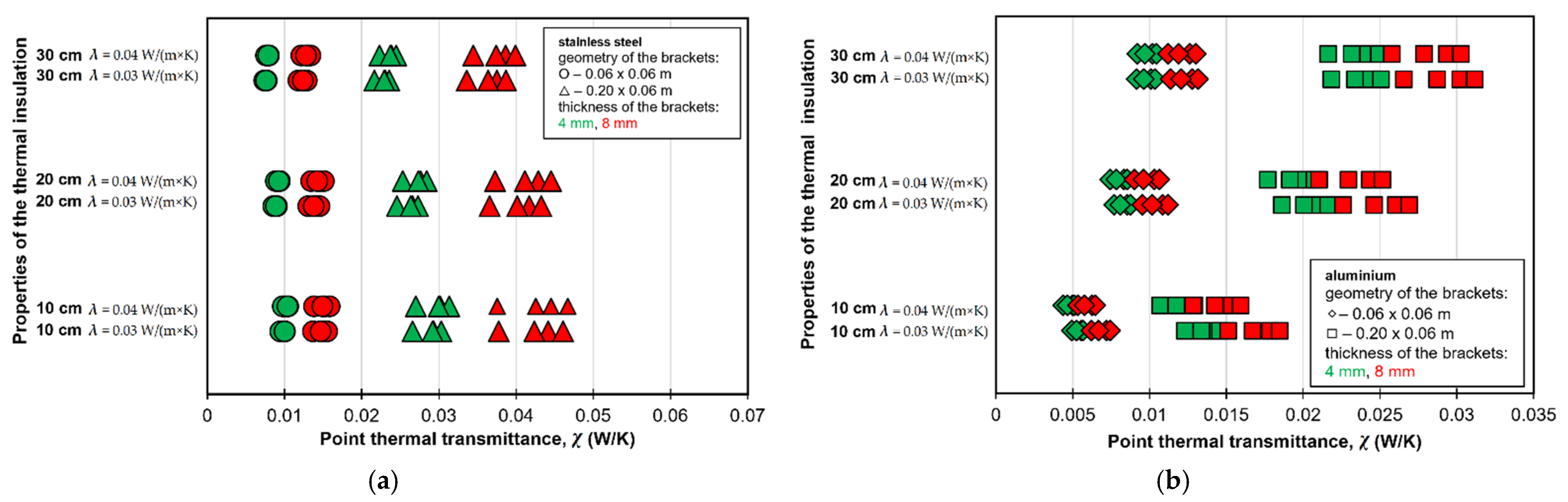
3.3. Effect of the Properties of the Brackets and Thermal Insulation

The effect of different thicknesses and thermal conductivity of thermal insulations on the point thermal transmittances were also examined. In Figure 8, we show two cases, Figure 8a shows a reinforced concrete wall and Figure 8b a masonry wall. In both cases, different brackets were fixed in a sliding position using a single anchor. Brackets with a different geometry were represented using different markers, while thicknesses were represented with different colours (Figure 8). There are considerable differences in the point thermal transmittances due to the thickness of the brackets. The 8 mm thick brackets tend to have much larger values than the 4 mm thick brackets. Therefore, choosing thinner brackets can save a lot of energy, primarily if RC walls or masonry walls with lower thermal resistance are used, and if mechanical calculations allow them to be used. The thickness of the thermal insulation does not cause large differences in the point thermal transmittance considering the thickness of the brackets. However, with more thermal insulation on the supporting wall construction, differences in the point thermal transmittance caused by the thickness of the brackets are reduced slightly in the case of RC wall (Figure 8a) and increased slightly in the case of masonry wall (Figure 8b).
Comparing the effect of adding thermal insulation, there is a significant difference between the different wall materials. In the case of RC walls, the decrease can be up to 30% if we choose 30 cm thermal insulation instead of 10 cm. Using large brackets, the relative difference is smaller than using small brackets. While adding more thermal insulation to the RC wall, it can decrease the point thermal transmittances, and more thermal insulation will increase the point thermal transmittances on modern masonry walls. This effect can be explained by the difference in the wall materials’ thermal resistance.
This effect was also seen in [5,6,8,12,39]. We can extend their statements by concluding that choosing thicker thermal insulation in the case of ceramic masonry walls can increase the point thermal transmittance by more than 45% for both small and large brackets. Therefore, it is crucial to deal with the heat loss of brackets in detail since simply choosing thicker thermal insulation does not solve the case of point thermal transmittances.

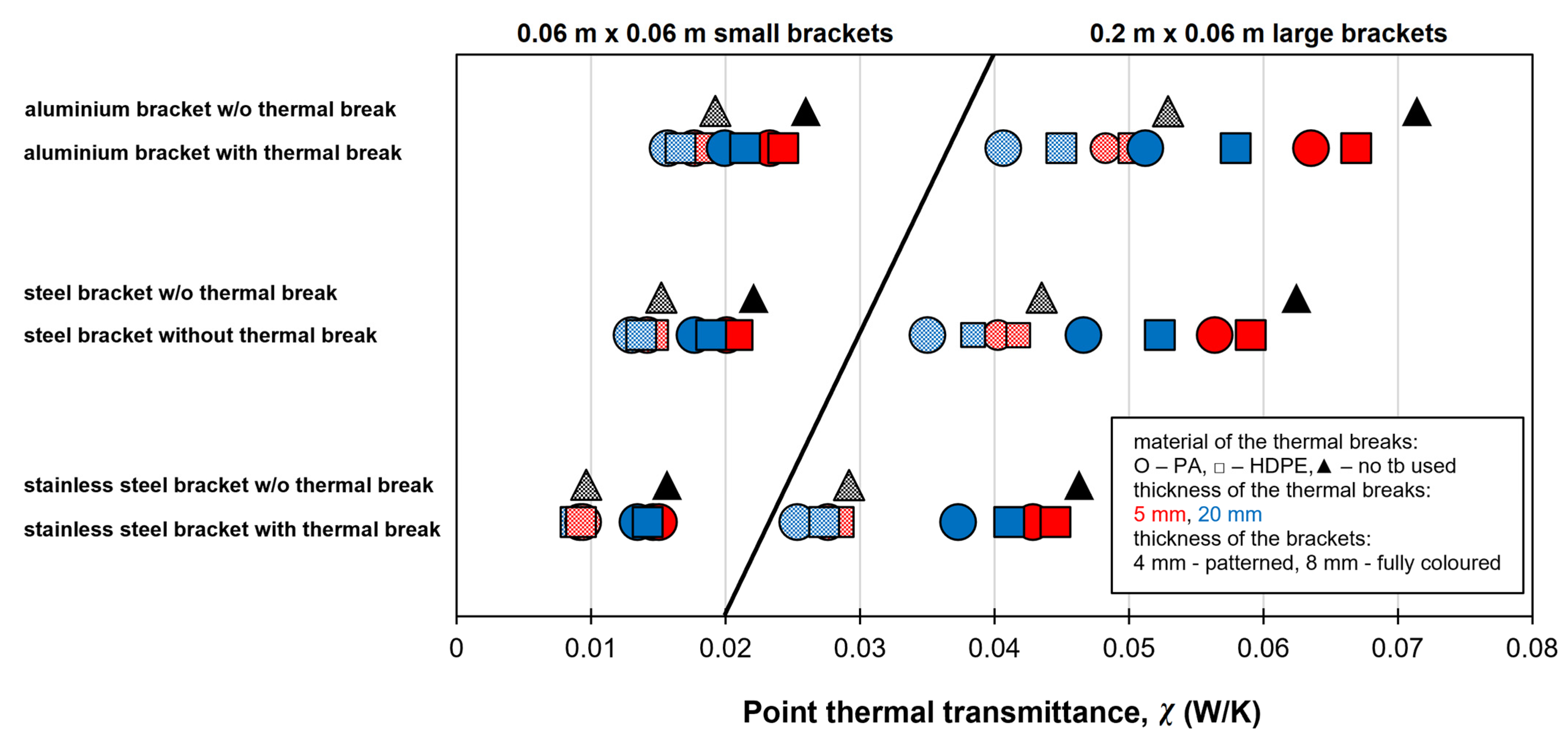
3.4. Effect of the Properties of the Brackets and Thermal Breaks

The effect of the bracket and thermal break properties, such as its material, thickness and geometry, was also evaluated. A case with an RC wall and 20 cm thermal insulation were displayed in Figure 9. Previous studies [8,11] also investigated the effect of different metal brackets on the point thermal transmittance. However, they only examined brackets made of galvanised steel with several lengths, whereas we examined brackets of 3 different materials (stainless steel, steel and aluminium) with various geometries.
After evaluating the results of the numerical modelling, it can be said that the point thermal transmittance of the brackets is significantly affected by the geometry, material and thickness of the brackets. Thicker brackets can increase χ by at least 26% (small stainless-steel brackets) and up to 60% (large aluminium brackets). Brackets with higher thermal conductivity can increase the point thermal transmittance by at least 27% (large brackets) and up to 48% (small brackets). Choosing large brackets over small ones can increase the point thermal transmittance value by 61 to 67%. Although we did not examine the mechanical performance of the brackets within the framework of the research, based on the results, it can be said that during the design process, it is worth choosing the smallest and thinnest statically appropriate brackets since this way the heat losses on the façade surfaces can be significantly reduced. It is also more favourable based on economic and sustainability aspects since less material is used.
Based on the evaluation of the thermal breaks, also illustrated in Figure 9, it can be said that the existence, material and thickness of the thermal breaks do not terminate the heat loss of the brackets. The latter statement is, unfortunately, a widespread belief of practitioners, but it is rebuttable by performing the numerical modelling as some previous studies also concluded [8,12], especially for stainless steel brackets. Besides our study, researchers also examined glass fibre-reinforced brackets [8]. They concluded that the difference in results of 3D simulations with thermal breaks and without them is almost equal to zero (0.0–0.3%). Using stainless steel brackets, the difference is up to 0.9%, steel brackets up to 5.5% and aluminium brackets vary from 4.8% to 5.7%. Therefore, we only tested PA and HDPE thermal breaks with 5 mm to 20 mm thickness.
Based on our models, we can say that 20 mm thick thermal breaks can reduce the χ by at least 2% for small stainless-steel brackets and up to 24% for large aluminium brackets. If the thermal breaks were constructed from 5 mm thick PA, they could reduce the large aluminium brackets by up to 12% point thermal transmittance. Comparing the different thermal breaks available, even a 20 mm thick PA isolator can save only 28% on an RC wall. Therefore, it is visible that if we only consider thermal aspects, the use of thermal isolators may only be worth the effort with aluminium brackets. However, we recommend calculating the economic aspects of using thermal breaks before applying them.

3.5. Thermal Bridge Catalogues

We created a comprehensive thermal bridge catalogue based on the total 41,118 FEM-based numerically modelled point thermal transmittance values (see Figure 10). In order to compile the results into a manageable catalogue, two result summary tables were created; one containing the point thermal transmittance obtained from the simulation of models without thermal breaks and the other with thermal breaks. The materials were sorted along the wall constructions of different materials and widths, insulations of different thicknesses, thermal conductivity and the anchor length. A drop-down list-based search list also facilitates the finding of the appropriate values for the given parameters. The thermal bridge catalogue can be found as a supplementary materials to the article in Excel format to help readers and practitioners use the study results.

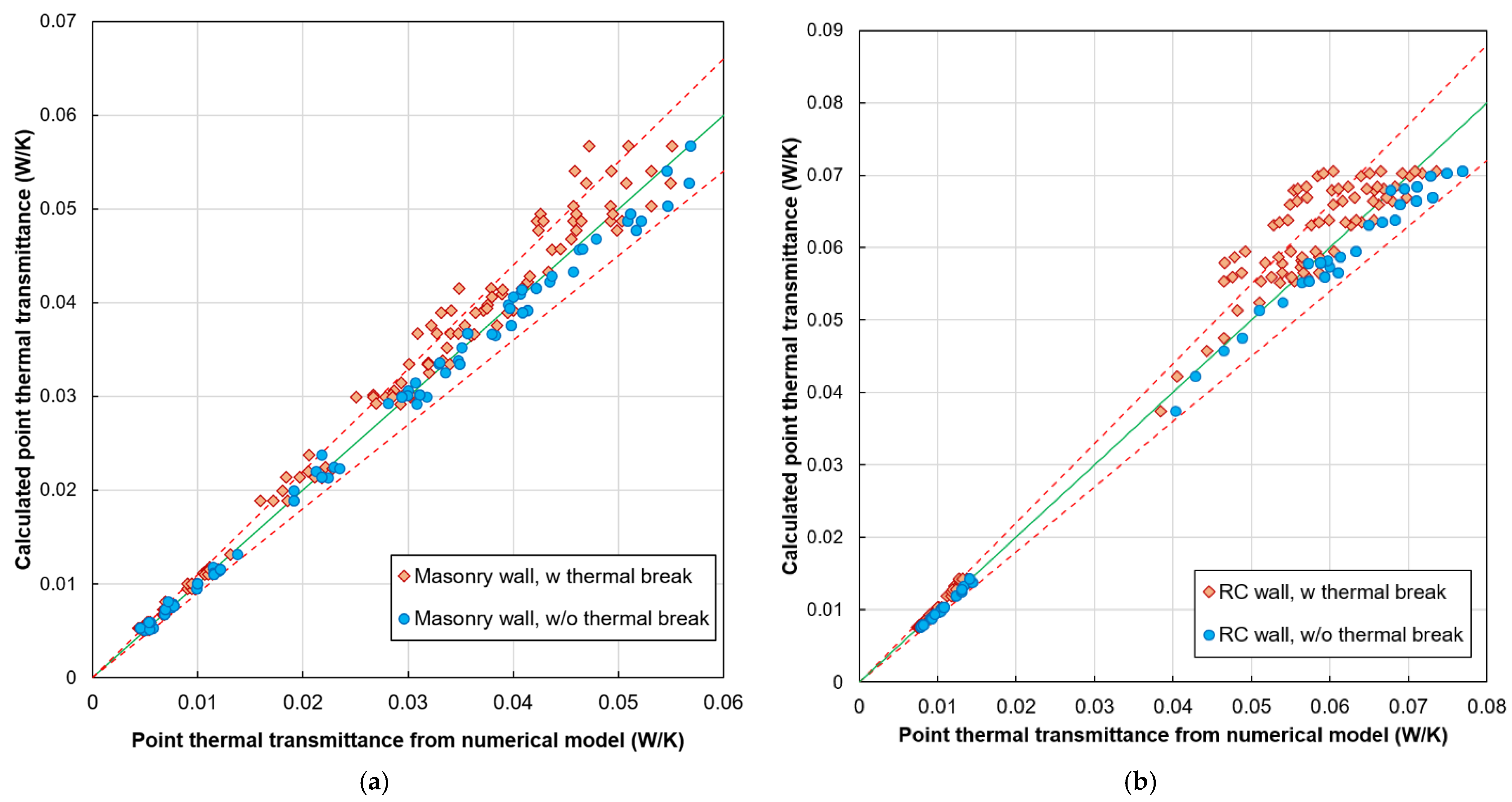
3.6. Simplified Method

In addition to the thermal bridge catalogue, a new simplified method was also created based on the results of the numerical models and the calculation of the effect of the mechanical fasteners according to ISO 6946 Annex F [9]. The new simplified method is created to handle the brackets’ effect with only slight modifications to the original equation in [9]. The basic structure of the equation has remained, but a new “α” multiplication correction factor is created for the equation that considers the effect of the brackets, as well as some of the components ( A b , λ b ) now represent the brackets instead of the cylindrical mechanical fasteners as follows in Equation (8):
Δ U f , b   [ W m 2 × K ] = α × n × A b × λ b d 0 × ( R 1 R t h ) 2
where U f , b is the point thermal transmittance of the brackets (W/(m2 × K)), n is the number of the brackets (1/m2), A b is the surface area of the bracket penetrating the thermal insulation layer (m2), λ b is the thermal conductivity of the bracket’s material (W/(m × K)), d 0 is the thickness of the penetrated thermal insulation (m), R 1 is the thermal resistance of the penetrated thermal insulation ((m2 × K)/W) and R t h is the total thermal resistance of the cross-section without correction factors ((m2 × K)/W). The “α” coefficient was created to get the numerical modelling results back with less than ±10% deviation compared to the numerical models in case of no thermal breaks applied. As visible in Equation (8), this simplified method neglects the existence and properties of thermal breaks. However, if this method calculates the correction of brackets with thermal breaks, the results will deviate in favour of safety.
In tabular form, we compared point thermal transmittance for certain parameter combinations. We checked the difference between the results calculated in the original form of the correction formula and the χ-values obtained from the simulation. During the investigation, we concluded that changing the geometry and material of the bracket causes significant differences in the values of the point thermal transmittance at the point, changing the thermal conductivity of the thermal insulation and the properties of the dowels, and the existence of the thermal breaks only results in differences within 10%. Based on these, we chose the strategy of examining the cases belonging to the specific thermal insulation, wall and bracket properties in separate groups and finding what constant multiplier we can use to achieve for the correction formula to return the results of the simulation within an error margin under ±10% in case of no thermal breaks applied. We tested and created multiplication correction factors for both evaluated bracket types; therefore, α factors can handle aluminium, steel and stainless-steel brackets. Since we concluded that thermal breaks have relatively small effects on the point thermal transmittance, we neglected them. We considered this simplification to halve the number of the multiplication correction factors. The multiplication correction factors were also created to handle a range between insulation thicknesses (0.1, 0.2 and 0.3 m) and thermal conductivity of the insulation (0.3 and 0.4 W/(m × K), as well as small (0.06 m) to large (0.2 m) brackets with different thicknesses (0.004 to 0.008 m). Any values between these values can be calculated using linear interpolation.
In the case of masonry walls, seven tables were created containing “α” multiplication correction factors, considering all the walls’ tested wall thicknesses and thermal conductivity factors. For example, Table 4 shows the table for a 30 cm thick ceramic masonry wall with a thermal conductivity of λ = 0.19 W/(m × K). In the top row of the table, we can find the values for the different thermal insulation properties. In contrast, in the leftmost column, we can find the values for the different thermal conductivity of the brackets, depending on the geometry of the brackets.
In the case of a reinforced concrete wall, it was sufficient to create only one table (see Table 5) because the tests showed that due to the relatively high thermal conductivity of the RC wall (2 to 2.5 W/(m × K)), the wall thickness and the thermal conductivity do not have a significant effect on the point thermal transmittance.
Table 4 and Table 5, and the other six tables (Tables S1–S6) for masonry walls with other thicknesses, can be found as Supplementary Materials to the article in Excel format.
To validate the simplified method, we performed a comparison represented in Figure 11. We examined the differences between the results obtained from the numerical simulation and the calculated ones with the chosen multiplication factors in the case of reinforced concrete walls and masonry walls. Based on the graphs, it can be said that for both wall types, in the cases without thermal breaks, the deviation was kept within the 10% margin of error; therefore, the simplified method met its expectations. However, when thermal breaks were added, some deviations, especially at higher point thermal transmittance values, were slightly greater than 20%. However, the deviation of the simplified method was in the positive direction in favour of safety.

4. Conclusions

During the research, the effect of the parameters was investigated on a broader scale than most of the previous research revealed during the literature review. Numerical simulations have been carried out to predict the effects of metal fasteners on the thermal performance of the building envelope. The main findings can be summarised as follows within the range of the tested parameters:
  • The thermal resistance (thickness of the wall/thermal conductivity of the wall) of the wall significantly affects the point thermal transmittance (χ) of the brackets.
  • The point thermal transmittances (χ) of the brackets are not significantly affected by the number, the material of anchors, dowels, and drill hole length.
  • The point thermal transmittances (χ) of the brackets are not significantly affected by the thermal conductivity of the thermal insulation.
  • The point thermal transmittances (χ) of the brackets are significantly affected by the thickness of the thermal insulation.
  • The point thermal transmittances (χ) of the brackets are significantly affected by their geometry (size), material and thickness of the brackets.
  • The thermal breaks can reduce the point thermal conductivity much less than expected, especially when stainless-steel brackets are used.
Overall, it can be said that the results of the numerical simulations clearly show that, for mechanical fixings, only considering the anchors and the doweling is not sufficient. The effect of the brackets on the point thermal transmittance is also significant. Using the results of tens of thousands of numerical models, we created a point thermal bridge catalogue. In the research framework, besides creating the catalogue, we created a simplified method using a multiplication correction factor in tabular form. The resulting catalogue and simplified method can be used in cost-effectiveness studies and promotes the further development of load-bearing structures and the development of their design. There are also further research opportunities such as multiphysical tests (e.g., combined heat and moisture transport) or structural analysis (e.g., effect of construction inaccuracies, deformation of the bracket).

Supplementary Materials

The following supporting information can be downloaded at: https://www.mdpi.com/article/10.3390/buildings12081153/s1. FP-BN_Thermal_bridge_catalogue_v1.0.zip.

Author Contributions

Conceptualisation, B.N.; methodology, B.N.; investigation, F.P. and B.N.; data curation, B.N.; writing—original draft preparation, F.P. and B.N.; writing—review and editing, B.N.; validation, B.N.; visualisation, F.P. and B.N.; supervision, B.N. All authors have read and agreed to the published version of the manuscript.

Funding

The first author was supported by the ÚNKP-21-1 New National Excellence Program of the Ministry for Innovation and Technology from the source of the National Research, Development and Innovation Fund. The corresponding author was supported by the ÚNKP-21-4 New National Excellence Program of the Ministry for Innovation and Technology from the source of the National Research, Development and Innovation Fund. Project FK_128663 has been implemented with the support provided from the National Research, Development and Innovation Fund of Hungary, financed under the FK_18 funding scheme.

Institutional Review Board Statement

Not applicable.

Informed Consent Statement

Not applicable.

Data Availability Statement

Not applicable.

Conflicts of Interest

The authors declare no conflict of interest.

References

  1. Urbán, D.; Roozen, N.B.; Zatko, P.; Rychtáriková, M.; Tomašovič, P.; Glorieux, C. Assessment of sound insulation of naturally ventilated double skin facades. Build. Environ. 2016, 110, 148–160. [Google Scholar] [CrossRef] [Green Version]
  2. Zamora Mestre, J.L.; Niampira, A. Lightweight ventilated façade: Acoustic performance in laboratory conditions, analysing the impact of controlled ventilation variations on airborne sound insulation. Build. Acoust. 2020, 27, 367–379. [Google Scholar] [CrossRef]
  3. Heindl, W.; Sigmund, A. Influence of air-backed bracket-mounted cladding on the thermal insulation of external walls. Bauphysik 1984, 6, 137–141. [Google Scholar]
  4. Anderson, B. Conventions for U-Value Calculations; The Building Research Establishment: Watford, UK, 2006. [Google Scholar]
  5. Kolesnyk, I. Determination of Linear and Point Thermal Transmittance of the Most Usual Thermal Bridges in External Walls. Bud. O Zoptymalizowanym Potencjale Energetycznym 2013, 2, 47–54. [Google Scholar]
  6. Šadauskiene, J.; Ramanauskas, J.; Šeduikyte, L.; Daukšys, M.; Vasylius, A. A simplified methodology for evaluating the impact of point thermal bridges on the high-energy performance of a Passive House. Sustainability 2015, 7, 16687–16702. [Google Scholar] [CrossRef] [Green Version]
  7. García, B.Z.; Goikolea, B.A.; Martín, J.M.G.; Hernández García, J.L. Comparison of theoretical heat transfer model with results from experimental monitoring installed in a refurbishment with ventilated façade. IOP Conf. Ser. Earth Environ. Sci. 2020, 410, 012104. [Google Scholar] [CrossRef]
  8. Levinskytė, A.; Bliūdžius, R.; Kapačiūnas, R. The comparison of a numerical and empirical calculation of thermal transmittance of ventilated facade with different heat-conductive connections. J. Sustain. Archit. Civ. Eng. 2018, 23, 39–48. [Google Scholar] [CrossRef]
  9. ISO 6946:2017; Building Components and Building Elements. Thermal Resistance and Thermal Transmittance. International Organization for Standardization: Geneve, Switzerland, 2017.
  10. ISO 10211:2017; Thermal Bridges in Building Construction—Heat Flows and Surface Temperatures—Detailed Calculations. International Organization for Standardization: Geneve, Switzerland, 2017.
  11. Alghamdi, A.; Alharthi, A.; Alanazi, A.; Halawani, M. Effects of Metal Fasteners of Ventilated Building Facade on the Thermal Performances of Building Envelopes. Buildings 2021, 11, 267. [Google Scholar] [CrossRef]
  12. Nowak, K.; Byrdy, A. Effect of mounting brackets on thermal performance of buildings with ventilated facades. J. Build. Phys. 2019, 43, 46–56. [Google Scholar] [CrossRef]
  13. Doda, A. Thermal Bridging in Rainscreen Cladding. Available online: https://www.patrickryanassociates.com/media/files/Cold-Bridging-in-Rainscreen-Cladding-System.pdf (accessed on 30 June 2022).
  14. Sadauskiene, J.; Ramanauskas, J.; Vasylius, A. Impact of Point Thermal Bridges on Thermal Properties of Buidling Envelopes. Therm. Sci. 2020, 24, 2181–2188. [Google Scholar] [CrossRef] [Green Version]
  15. Hilti Ventilated Facades Technical Manual V1.0. Available online: https://www.hilti.hu/content/dam/documents/pdf/e4/engineering/manuals/MFT_Technical%20Manual%20PRINTING%20V1.0%20low.pdf (accessed on 30 June 2022).
  16. Ujma, A.; Pomada, M. Analysis of the temperature distribution in the place of fixing the ventilated facade. E3S Web Conf. 2019, 97, 01041. [Google Scholar] [CrossRef]
  17. Theodosiou, T.G.; Tsikaloudaki, A.G.; Kontoleon, K.J.; Bikas, D.K. Thermal bridging analysis on cladding systems for building facades. Energy Build. 2015, 109, 377–384. [Google Scholar] [CrossRef]
  18. Theodosiou, T.; Tsikaloudaki, K.; Bikas, D. Analysis of the Thermal Bridging Effect on Ventilated Facades. Procedia Environ. Sci. 2017, 38, 397–404. [Google Scholar] [CrossRef]
  19. Theodosiou, T.; Tsikaloudaki, K.; Tsoka, S.; Chastas, P. Thermal bridging problems on advanced cladding systems and smart building facades. J. Clean. Prod. 2019, 214, 62–69. [Google Scholar] [CrossRef]
  20. Ingeli, R.; Gašparík, J.; Paulovičová, L. Impact of an innovative solution for the interruption of 3-D point thermal bridges in buildings on sustainability. Sustainability 2021, 13, 11561. [Google Scholar] [CrossRef]
  21. Šadauskienė, J.; Ramanauskas, J.; Šeduikytė, L.; Buska, A. Assessment of buildings with ventilated facade systems and evaluation of point thermal bridges. J. Sustain. Archit. Civ. Eng. 2015, 11, 59–71. [Google Scholar] [CrossRef]
  22. Grauer, M. Ventilated rainscreen cladding system subframe contribution to annual source energy use in mid-size office buildings. Energy Build. 2019, 187, 269–280. [Google Scholar] [CrossRef]
  23. Salvalai, G.; Sesana, M.M. Experimental Analysis of Different Insulated Façade Technologies in Summer Condition. J. Green Build. 2019, 14, 77–91. [Google Scholar] [CrossRef]
  24. Olshevskyi, V.; Statsenko, E.; Musorina, T.; Nemova, D.; Ostrovaia, A. Moisture Transfer in Ventilated Facade Structures. MATEC Web Conf. 2016, 53, 01010. [Google Scholar] [CrossRef] [Green Version]
  25. Feris, P.; Strachan, P.; Dimoudi, A.; Androutsopoulos, A. Investigation of the performance of a ventilated wall. Energy Build. 2011, 43, 2167–2178. [Google Scholar]
  26. Sharma, A.; Mishra, K.B. Experimental investigations on the influence of ‘chimney-effect’ on fire response of rainscreen façades in high-rise buildings. J. Build. Eng. 2021, 44, 103257. [Google Scholar] [CrossRef]
  27. Kosínski, P.; Brzyski, P.; Suchorab, Z.; Łagód, G. Heat Losses Caused by the Temporary Influence of Wind in Timber Frame Walls Insulated with Fibrous Materials. Materials 2020, 13, 5514. [Google Scholar] [CrossRef]
  28. Rahiminejad, M.; Kholvalyg, D. Thermal resistance of ventilated air-spaces behind external claddings; definitions and challenges (ASHRAE 1759-RP). Sci. Technol. Built Environ. 2021, 27, 788–805. [Google Scholar] [CrossRef]
  29. Domínguez-Torres, C.A.; León-Rodríguez, Á.L.; Suárez, R.; Dominguez-Delgado, A. Empirical and Numerical Analysis of an Opaque Ventilated Facade with Windows Openings under Mediterranean Climate Conditions. Mathematics 2022, 10, 163. [Google Scholar] [CrossRef]
  30. Ibañez-Puy, M.; Vidaurre-Arbizu, M.; Sacristán-Fernández, J.A.; Martín-Gómez, C. Opaque Ventilated Façades: Thermal and energy performance review. Renew. Sustain. Energy Rev. 2017, 79, 180–191. [Google Scholar] [CrossRef]
  31. Gagliano, A.; Aneli, S. Analysis of the energy performance of an Opaque Ventilated Façade under winter and summer weather conditions. Sol. Energy 2020, 205, 531–544. [Google Scholar] [CrossRef]
  32. Heat Transfer Module User’s Guide; COMSOL Multiphysics® v. 5.6; COMSOL AB: Stockholm, Sweden, 2021.
  33. TNM Decree 7/2006. On the Determination of the Energy Performance of Buildings. Available online: https://njt.hu/jogszabaly/2006–7-20–6F (accessed on 30 June 2022).
  34. Hallik, J.; Kalamees, T. A new method to estimate point thermal transmittance based on combined two-dimensional heat flow calculation. E3S Web Conf. 2020, 172, 08005. [Google Scholar] [CrossRef]
  35. Yang, W.; Šadauskien, J.; Ramanauskas, J.; Krawczyk, D.A.; Klumbyt, E.E.; Fokaides, P.A. Investigation of Thermal Bridges of a New High-Performance Window Installation Using 2-D and 3-D Methodology. Buildings 2022, 12, 572. [Google Scholar]
  36. MSZ 24140:2015; Power Engineering Dimensioning Calculuses of Buildings and Building Envelope Structures. Hungarian Standards Institution: Budapest, Hungary, 2015.
  37. Arregi, B.; Garay, R.; Garrido-Marijuan, A. Assessment of thermal performance and surface moisture risk for a rear-ventilated cladding system for façade renovation. IOP Conf. Ser. Earth Environ. Sci. 2020, 410, 012102. [Google Scholar] [CrossRef]
  38. Nagy, B.; Stocker, G. Numerical Analysis of Thermal and Moisture Bridges in Insulation Filled Masonry Walls and Corner Joints. Period. Polytech. Civ. Eng. 2019, 63, 446–455. [Google Scholar] [CrossRef] [Green Version]
  39. Arregi Goikolea, B.; Garay Martinez, R.; Riverola Lacasta, A.; Chemisana Villegas, D. Heat transfer through anchoring elements in a rear-ventilated rainscreen insulation system for façade retrofit. In Proceedings of the Construction Pathology, Rehabilitation Technology and Heritage Management (REHABEND 2018 Congress), Cáceres, Spain, 15–18 May 2018. [Google Scholar]
Figure 1. Structure of a ventilated façade cladding acting as a parasol-umbrella.
Buildings 12 01153 g001
Figure 2. (a) Ventilated façade construction with large aluminium brackets using thermal break [15], (b) parametric geometry model of concrete wall with a large aluminium bracket and thermal break created in Comsol used for the numerical modelling.
Buildings 12 01153 g002
Figure 3. 3D models showing the results using vertical and horizontal sections for (a) temperature distribution (°C) and (b) heat flux density (W/m2).
Buildings 12 01153 g003
Figure 4. Temperature distribution (°C) in 2D vertical (a) and horizontal (b) sections.
Buildings 12 01153 g004
Figure 5. Heat flux density (W/m2) in 2D vertical (a) and horizontal (b) sections.
Buildings 12 01153 g005
Figure 6. Heat flux vectors around the brackets in the vertical (a) and horizontal (b) section.
Buildings 12 01153 g006
Figure 7. The effect of wall thickness and type and anchors. 20 cm, λ = 0.04 W/(m × K) thermal insulation penetrated with small (0.06 m × 0.06 m × 0.004 m) aluminium brackets equipped with 5 mm PA thermal breaks.
Buildings 12 01153 g007
Figure 8. (a) Stainless steel brackets with thermal breaks fixed with a single 5 cm long anchor steel anchor in 20 cm thick RC wall. (b) Aluminium brackets with thermal breaks fixed with a single 5 cm long steel anchor in 30 cm thick masonry wall.
Buildings 12 01153 g008
Figure 9. Brackets fixed using a single 5 cm long steel anchor in 20 cm thick reinforced concrete wall with 20 cm thick λ = 0.04 W/(m × K) thermal insulation.
Buildings 12 01153 g009
Figure 10. Thermal bridge catalogue (extract).
Buildings 12 01153 g010
Figure 11. Comparison of calculated and numerical modelled point thermal transmittance in the case of masonry (a) or RC (b) wall.
Buildings 12 01153 g011
Table 1. Parameters used in the study.
ComponentThickness (cm)/
Width × Height (cm)
MaterialThermal Conductivity (W/(m × K))
Internal plaster1.5Lime–cement0.8
Wall25Masonry0.25
300.07, 0.19, 0.64
380.07, 0.19, 0.72
15, 20, 25, 30Reinforced concrete2, 2.5
External plaster1.5Lime–cement0.8
Insulation10, 20, 30Mineral wool0.03, 0.04
Dowels0.2PA0.25
Anchors5, 15Stainless steel17
5, 15Steel50
Thermal break0.5, 2PA0.25
0.5, 2HDPE0.5
Bracket0.2, 0.4/6 × 6, 6 × 20, 10 × 20Stainless steel17
0.2, 0.4/6 × 6, 6 × 20, 10 × 20Steel50
0.2, 0.4/6 × 6, 6 × 20, 10 × 20Aluminium160
Table 2. Mesh statistics of automatic meshing.
Mesh TypeElementsDoFMeshing TimeCalculation Error
Extremely fine2,455,5563,313,544690 s-
Extra fine849,7321,154,22899 s0.48%
Finer375,266513,09433 s1.33%
Fine207,507285,97817 s2.37%
Normal125,816174,79112 s3.24%
Coarse58,68882,8816 s5.41%
Coarser27,24439,2335 s7.98%
Extra coarse13,40319,6054 s11.45%
Extremely coarse450366994 s20.00%
Table 3. Mesh statistics of user-controlled meshing.
Mesh TypeElementsDoFMeshing TimeCalculation Error
Fine + extra fine207,507285,97813 s2.37%
Finer + extra fine375,266513,09426 s1.33%
Table 4.α” multiplication correction factors for 30 cm thick masonry wall (λ = 0.19 W/(m × K)).
Thermal Conductivity of the Brackets [W/(m × K)]The Geometry of the Brackets [h × t]Thickness of Insulation [m]
0.10.20.3
Thermal Conductivity of Insulation [W/(m × K)]
0.030.040.030.040.030.04
17
(stainless steel)
0.06 × 0.0040.3200.2082.0001.2005.2003.200
0.06 × 0.0080.2240.1441.4400.9204.4002.560
0.2 × 0.0040.2240.1441.4400.9204.4002.560
0.2 × 0.0080.1760.1041.1200.7203.4402.000
50
(steel)
0.06 × 0.0040.1280.0800.9600.5602.8001.760
0.06 × 0.0080.0880.0880.6400.4002.0001.280
0.2 × 0.0040.1040.0560.7200.4402.2401.440
0.2 × 0.0080.0640.0640.4800.2961.5200.960
160
(aluminium)
0.06 × 0.0040.0440.0290.3440.2241.1200.720
0.06 × 0.0080.0290.0190.2160.1440.7200.480
0.2 × 0.0040.0340.0220.2560.1600.8800.560
0.2 × 0.0080.0220.0140.1600.1040.5600.320
Table 5.α” multiplication correction factors for reinforced concrete wall.
Thermal Conductivity of the Brackets [W/(m × K)]The Geometry of the Brackets [h × t]Thickness of Insulation [m]
0.10.20.3
Thermal Conductivity of Insulation [W/(m × K)]
0.030.040.030.040.030.04
17
(stainless steel)
0.06 × 0.0040.3200.2082.0001.2565.6003.360
0.06 × 0.0080.2400.1601.6801.0404.8002.880
0.2 × 0.0040.2960.1841.8401.0805.2003.200
0.2 × 0.0080.2240.1361.4800.8804.1602.560
50
(steel)
0.06 × 0.0040.1360.0881.0400.6403.2002.080
0.06 × 0.0080.0960.0640.7600.4802.4001.520
0.2 × 0.0040.1200.0800.9200.5602.8001.760
0.2 × 0.0080.0880.0560.6800.4002.0801.280
160
(aluminium)
0.06 × 0.0040.0480.0320.4000.2641.3600.880
0.06 × 0.0080.0320.0210.2720.1760.9200.560
0.2 × 0.0040.0400.0280.3360.2241.1200.720
0.2 × 0.0080.0300.0190.2320.1440.8000.480
Publisher’s Note: MDPI stays neutral with regard to jurisdictional claims in published maps and institutional affiliations.

