1. Introduction
Grouting is a concealed project, and grouting pressure is an important parameter [
1,
2,
3]. Grouting pressure can shorten the time for slurry permeation grouting and expand the diffusion scope of the slurry [
4,
5,
6,
7]. When slurry particles diffuse to rock cracks with openings that are smaller than the grain size, free water in slurry might be dehydrated when passing through intergranular spaces under grouting pressure [
8]. Particles pile up tightly at the crack end, blocking water and reinforcing the structure. Grouting material properties are another important parameter affecting the reinforcement of the rock-soil mass. The strength of the grout slurry plays the decisive role in the reinforcement of the rock-soil mass [
9,
10,
11,
12,
13,
14,
15,
16,
17,
18,
19].
Scientific researchers have discussed stone powder-cement material and clay-cement materials. Vardhan K. et al. [
20,
21,
22,
23,
24] studied stone powder mixed in cement slurry, mortar, and concrete as additives. When stone powder replaces 10% of the cement, the compressive strength of the material increases. Belaidi, A., Erguen, A. et al. [
25,
26] discussed the addition of stone powder and other additives in materials. When the stone powder replaces 5–10% of cement, both the fluidity and compressive properties of the materials increase. Bayesteh H. et al. [
27,
28] found that the water-cement ratio is another important factor influencing strength, except for the stone powder content. Zhang S. et al. [
29,
30,
31,
32,
33,
34] found that replacing about 20% of cement by kaolin can improve the compressive strength of cement slurry, mortar, and self-compacting concrete materials.
Currently, most scholars ignore the influences of environmental factors in practical engineering (e.g., pressure and permeation) on slurry grouting when studying the mechanical properties of stone powder and clay materials, resulting in major differences between laboratory tests and practical engineering in the strength of grout slurry. High-pressure grouting is conducive to the safe production of coal mines, but excessive grouting pressure may bring excessive strength surplus of grout slurry, thereby increasing the grouting costs [
35]. As a result, the laboratory test device must be improved, and the environment close to field situations must be simulated to provide technological support to the design of grouting materials.
With references to the influences of double-high curing conditions on the strength of grout slurry, a double-high-curing test device was developed independently based on conventional laboratory tests and principle, model, and relevant theories of slurry grouting under high permeability and high pressure. Moreover, the influencing laws of curing pressure (2, 4, 6, 8, and 10 MPa) on the strengths of stone powder-cement grout slurry and clay-cement grout slurry were investigated. A uniaxial model was built using PFC2D to analyze the crack evolution mechanism of slurry grouting.
This paper first analyzes the internal mechanism of the strength enhancement of the slurry under the pressure filtration. It is found that with the increase of the curing pressure, the dewatering of the slurry increases, the indirect contact force of the particle skeleton increases, and the strength of the stone body increases. Then, the failure process of the stone body in macro compressive mechanics and microcrack development is explained from the combination of the indoor test and the numerical simulation test. It is found that the strength of stone powder-cement slurry and clay-cement slurry stone body increases with the increase of curing pressure, and the failure process of the two kinds of slurry stone body goes through three continuous stages: continuous elasticity, crack expansion and strength failure, and finally tensile failure. The research results can provide a basis for the selection of ground pregrouting materials and grouting parameters.
2. Materials and Methods
2.1. Double-High Test Device
2.1.1. Principle
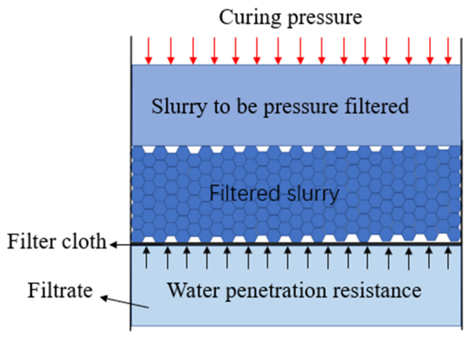
Under curing pressure, slurry experiences solid-liquid separation after passing through the filtering system, and the dehydrated slurry piles up into a filter cake on the filter cloth. Influenced by the curing pressure, the filter cake becomes increasingly thick, and the permeation resistance of the water molecules increases. When the curing pressure is equal to the permeability resistance of the water molecules, the double-high curing test is finished.
2.1.2. Model
According to the principle of curing pressure, the dehydration process of curing pressure was simplified into a double-high curing model. The double-high curing process of slurry is a process of continuous dehydration [
36] in which the pores in the slurry are reduced, the concentration increases, and the volume decreases. The simple model analysis of the double-high curing device is shown in
Figure 1.
2.1.3. Calculation Model of Double-High Curing Devices
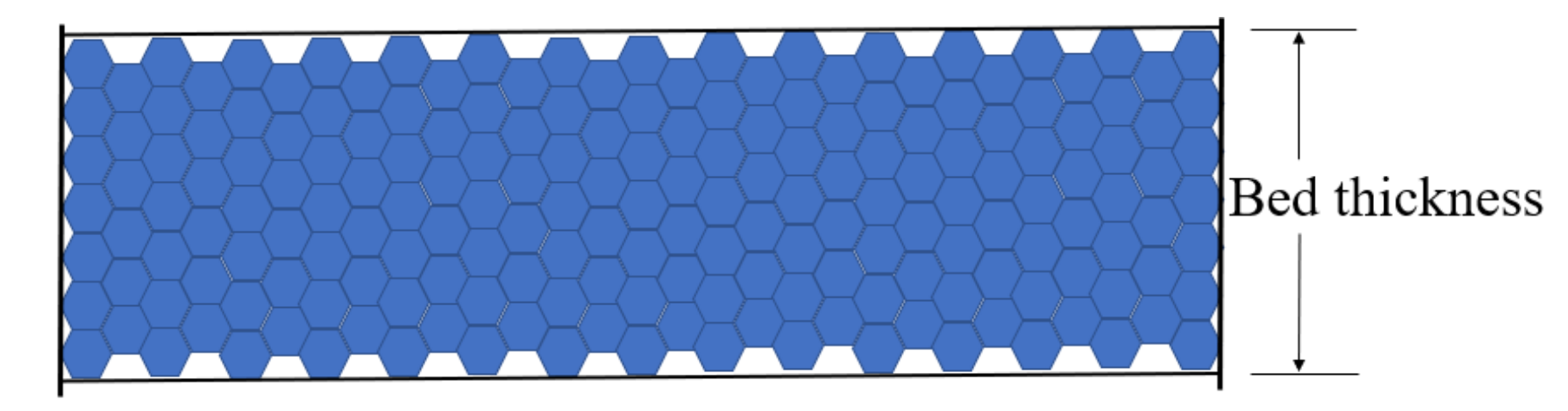
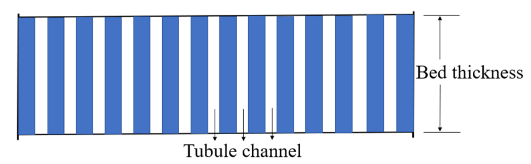
During the curing pressure of the slurry, the free water molecules in the lower slurry are discharged and form an L-thick bed (
Figure 2). The irregular channels of the curing pressure model in the bed are simplified into parallel vertical tubule channels (
Figure 3).
- (1)
The internal surface area of the tubule channels is equal to the surface area of all the particles.
- (2)
The flowing space in the tubule channels is the pore volume of the bed.
Figure 3.
Model of tubule channels in the bed.
Figure 3.
Model of tubule channels in the bed.
2.1.4. Relevant Theoretical Analyses
- (1)
Calculation of filter cake thickness
According to the prepared slurry, the volume fraction and suspension volume were calculated, and the dehydrated filter cake thickness was deduced [
37].
where
Φ is the volume fraction of the slurry.
V_
water is the volume of water in the slurry.
V_
solid is the volume of the solid in the slurry.
V_
suspension refers to the volume of the slurry.
V denotes the filter liquid volume at
t.
L is the thickness of the filter cake. A is the cross-section area of the slurry tank.
ε refers to the porosity of the filter cake.
q represents the filter liquid volume passing through the unit area.
- (2)
Calculation of curing pressure time
Suppose that the diameter of the tubule channel is
de, the pore volume in the bed is
ε, the surface area of the particles in the unit cubic meter of the bed is
ab, and the surface area of the particles is
a.
The gravity effect of the slurry was ignored. The density of the slurry and the flow rate in the tubule channels were and uL, respectively, and Le indicated the length of the bed after being simplified into the tubule channels. According to the model of the tubule channels, the pressure drop of the slurry when passing through the tubule channels is expressed as follows:
where Δ
P is the curing pressure value.
The relationship between the flow rate in tubule channels of slurry and the apparent flow rate (
u) was
When the flow rate was relatively low and the Reynolds number (
Re) of the bed was less than 2, then
where
μ was the viscosity of slurry.
The model parameter (
λ′) was gained from the test:
Combining Equations (1)–(6) and Carman’s Equation could yield
In the dehydration and separation processes of the slurry, the approximate filter constant (
K) was set to 5, and Carman’s Equation was deformed into a filtration rate formula:
where
L is the thickness of the filter cake at
t.
where
V_
cake is the volume of the filter cake;
V_
pore is the pore volume of the suspension;
refers to the porosity of the suspension;
V_
liquid is the ultimate water drainage of the slurry; and
T refers to the total dehydration time of the slurry.
2.1.5. Double-High Curing Device
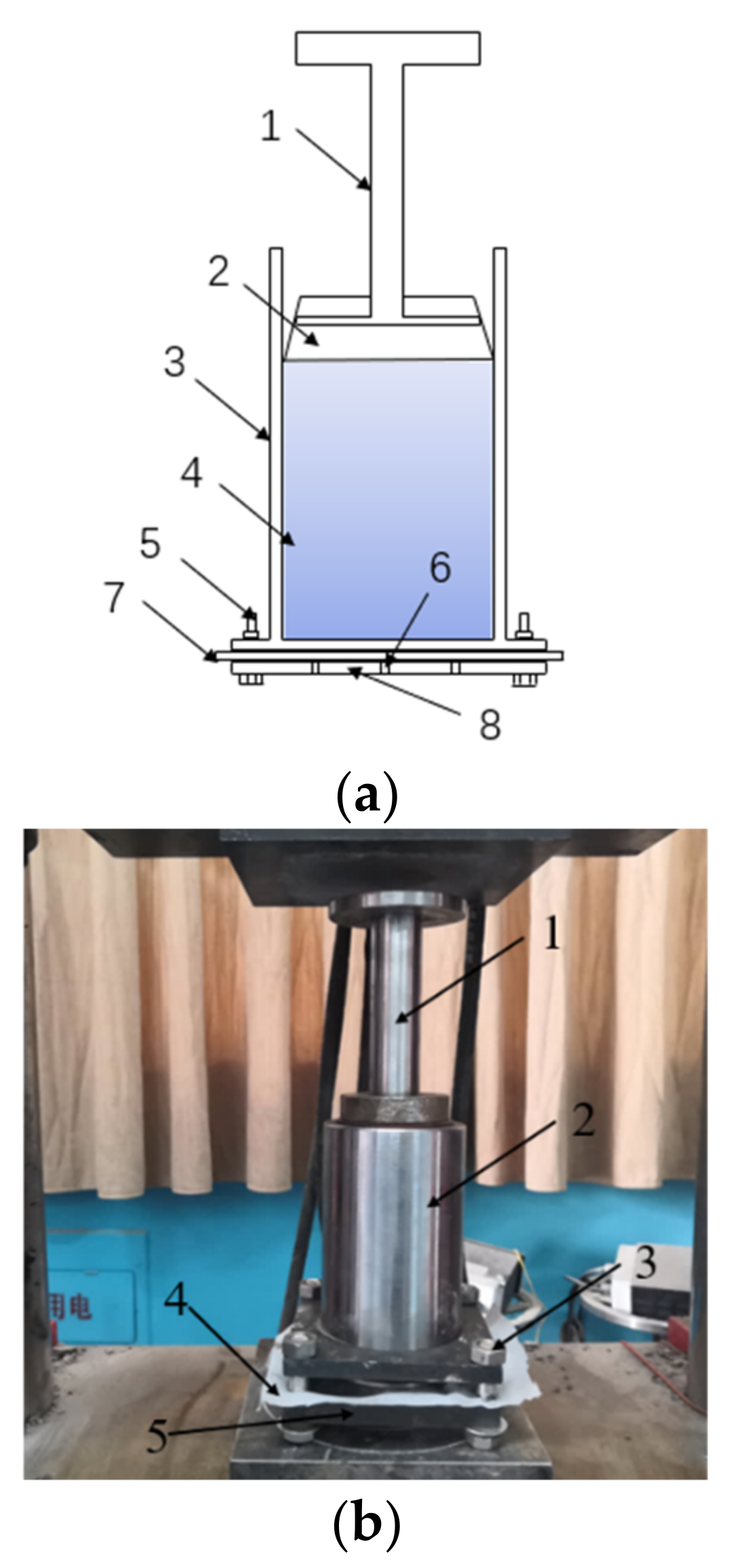
According to the relevant theories of curing pressure and the double-high curing device developed independently in the model, the strengths of the stone powder-cement grout slurry and clay-cement grout slurry under the different stresses were tested. The principle and model of the double-high curing device are shown in
Figure 4.
2.2. Materials
2.2.1. Materials
The clay was collected from a grouting station.
The stone powder was manufactured by Jiaozuo Qianye New Material Co., Ltd. The chemical composition is shown in
Table 1.
The cement, P O 42.5, is from Jiaozuo Qianye New Material Co., Ltd. The chemical composition is shown in
Table 2.
The water is ordinary tap water.
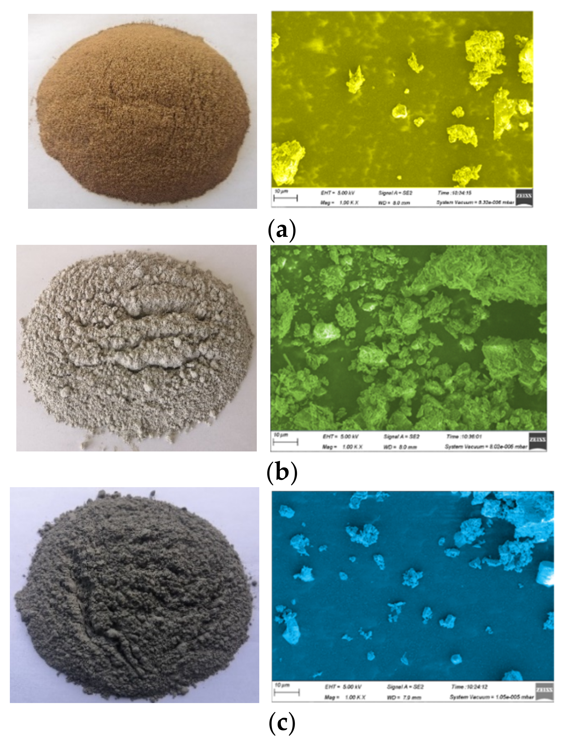
Sample images of the three raw materials and the particle appearance images were obtained (
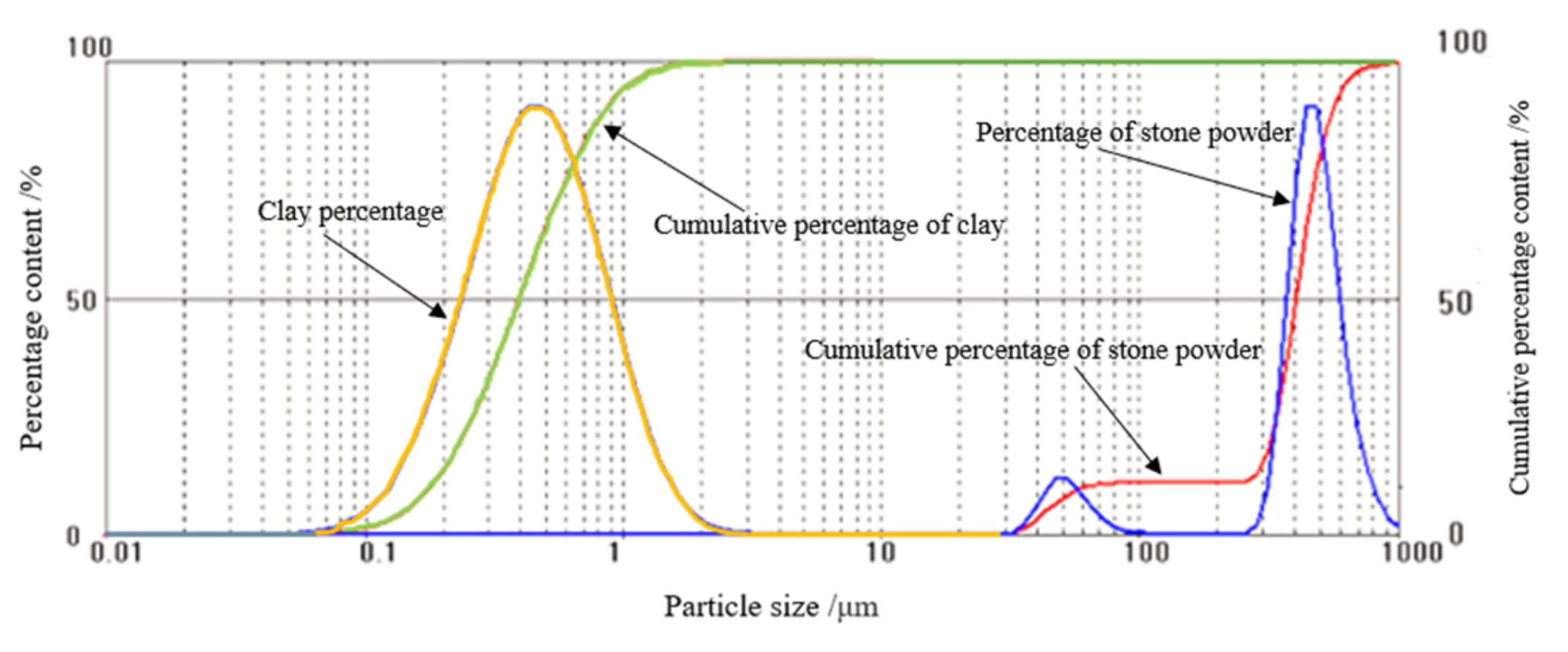
Figure 5). No obvious regular shapes were found in the clay, stone powder, and cement particles. Instead, they superposed mutually. The grain size curves of the clay and stone powder are shown in
Figure 6.
2.2.2. Mixing Ratio Design of Grouting Materials
To realize the grouting of the underground aquifer grouting materials, two types of grouting materials were prepared with raw materials based on fluidity conditions. The mechanical properties of these two types of grouting materials under different curing pressures were tested. The grouting material parameters are shown in
Table 3.
2.3. Methods
2.3.1. Specimen Preparation and Test Methods
Certain amounts of clay and water were poured into the mixing tank of the cement mortar mixer and then stirred at a low rate for 2 min. Stirring was stopped for 30 s, and a certain amount of cement was poured, followed by high-speed stirring for 3 min. Stirring was stopped again, and the clay-cement slurry was prepared. The stone powder-cement slurry was prepared in the same way.
The prepared clay-cement slurry was poured into the curing pressure device, and the double-high curing test began. After the slurry was consolidated, samples were collected by drilling. The standard slurry grouting sampling after pressure curing is shown in
Figure 7. Five curing pressures were designed, namely, 2, 4, 6, 8, and 10 MPa, with three specimens for each. The standard stone powder-cement slurry specimens were prepared in the same way.
After sampling, the standard cylinder specimens (25 × 50 mm) were collected. The microcomputer-controlled electronic universal testing machine was applied as the loading device, and the loading speed was set at 1 mm/min.
2.3.2. Crack Evolution Analysis
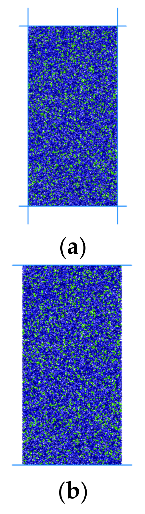
The uniaxial compression test of specimens will be accompanied by the change in the number of cracks in the process of compression failure. To study the stress-strain curve and the evolution law of the number of cracks in the failure process of specimens, a two-dimensional standard model of a 25 × 50 mm cylinder was established by PFC2D. Firstly, four walls are generated as the boundary to form a rectangular area. In this area, the circular particles are generated according to the radius of the cement particles and stone powder particles. Contact modulus and contact stiffness are applied between particles to provide the model with compressive strength, as shown in
Figure 8a. Then, the wall constraints on both sides were deleted to make the model in an unconfined compressive state in the compressive process, as shown in
Figure 8b. Finally, the upper and lower walls were used to load the specimen model to realize the uniaxial-compressive-loading simulation test. In the simulation test, five groups of models with curing pressures of 2 MPa, 4 Mpa, 6 Mpa, 8 Mpa, and 10 MPa were generated by adjusting the particle mesoscopic parameters. The mesoscopic parameters in the test block model are shown in
Table 4.
3. Results
3.1. Influencing Mechanism of Double-High Curing Conditions on Strength of Grout Slurry
3.1.1. Influencing Mechanism of Microstructure on Strength
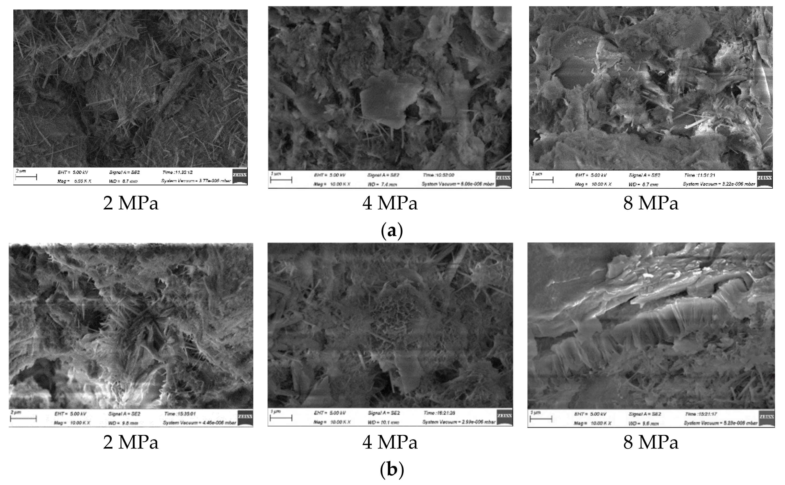
To discuss the influencing mechanism of the double-high curing conditions on the strength of the grout slurry, the microstructure of the grout slurry under 10,000 magnification was observed under a scanning electron microscope (SEM). Grout slurry samples with curing pressures of 2, 4, and 8 MPa and cured for 28 days were chosen to assume obvious differences in microstructure of the grout slurry under different curing pressures. The microstructures of the grout slurries are shown in
Figure 9.
At the curing pressure of 2 MPa, many pores were observed in the grout slurry, showing irregular spatial distribution. Needle-like ettringites were observed on the microstructural surface of the grout slurry, and the structure was relatively loose. When the curing pressure was 4 MPa, the porosity decreased, and the structure became relatively compact. Meanwhile, sheet-like hydration products were generated, and a dense network structure formed to bond the particle sand cement. The structure was relatively dense. When the curing pressure was 8 MPa, the sheet-like hydration products increased, and local tight piling was observed. The cement products and particles bonded tightly, and the pores decreased, thereby increasing the compaction of the structure. With the increase in curing pressure, the porosity of the grout slurry decreased gradually.
3.1.2. Influencing Mechanism of Squeezing Drainage on Strength
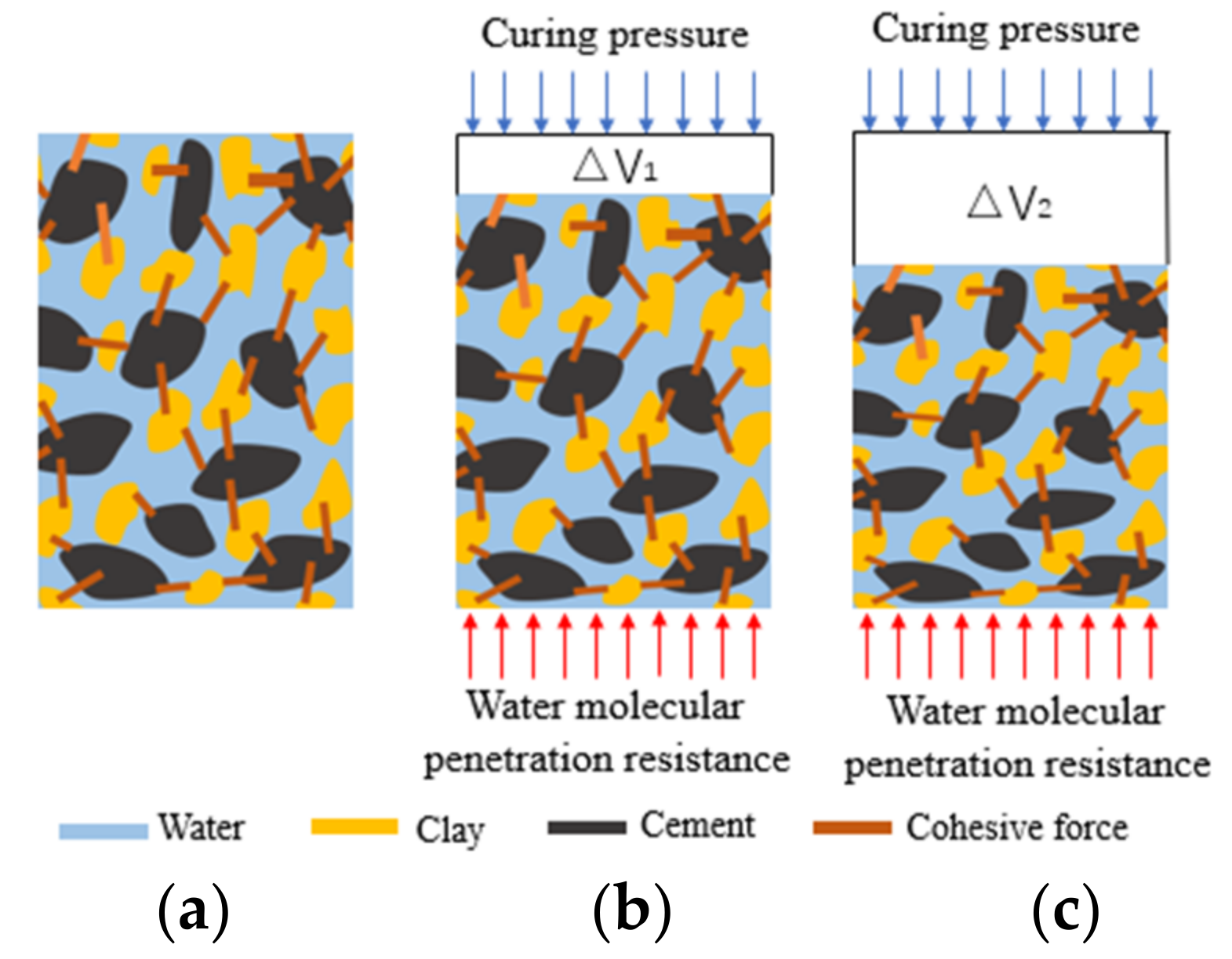
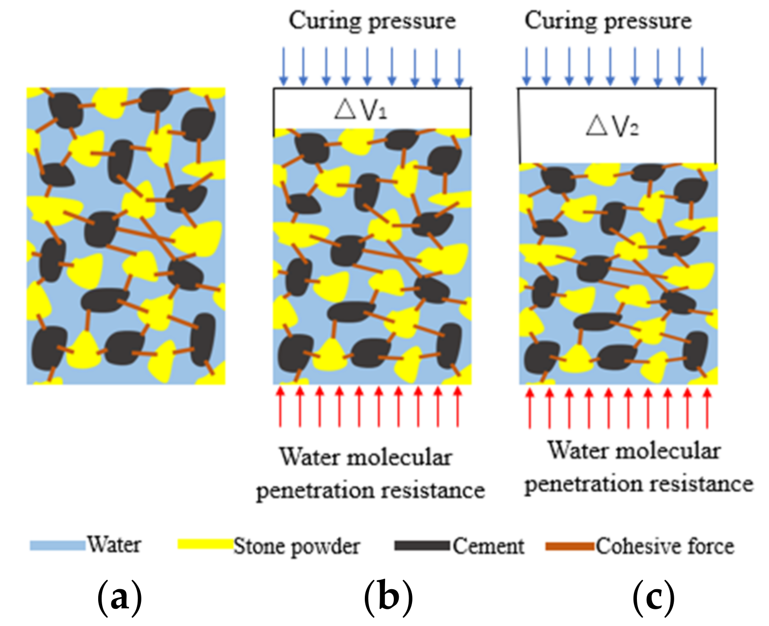
Based on the analysis of the pore structures of the grout slurry under the different curing pressures, the squeezing drainage processes of the clay-cement slurry and the stone powder-cement slurry under the different curing pressures were plotted by combining the squeezing drainage of the slurries (
Figure 10 and
Figure 11).
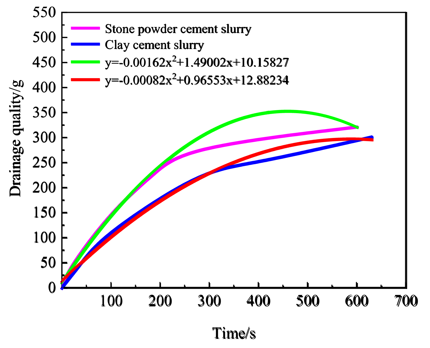
Some free water was drained from the slurry under curing pressure. This increased the slurry concentration and decreased the water-cement ratio of the slurry indirectly, finally increasing the strength of the grout slurry. To discuss variations in water drainage with time under different curing pressures, the variation laws of water drainage from the stone powder-cement slurry and clay-cement slurry with time under 4 MPa were discussed (
Figure 12).
Figure 11 shows that the curve variation trends of the different slurries in the curing pressure process were consistent. The variation functions of water drainage with time under curing pressure were fit by the multiphase mode, which conformed to the quadratic function relation of one variable. The fitting coefficient of water drainage from the stone powder-cement slurry was 0.989, whereas that for the clay-cement slurry was 0.997. Thus, variation laws of water drainage of the slurry with time conformed to the functional relationship. Finally, many reasons caused the low final water drainage from the clay-cement slurry compared with that from the stone powder-cement slurry. First, the double-electrode layers on the clay surface can adsorb some water, thus having relatively good water-retaining properties. As a result, the drainage resistance in the curing pressure increased, and the water drainage decreased. Second, clay has relatively strong hydrophilicity. Hydrogen ions and hydroxide ions on the clay surface absorb water molecules through hydrogen bonds, and chemical bonds have strong acting forces. Given the same pressure, the slurry leads to high-drainage resistance. Thus, under the same pressure and loading speed, the strength of the stone powder-cement grout slurry was higher than that of the clay-cement grout slurry.
The influencing mechanism of double-high curing conditions on the strength of the grout slurry can be summarized as follows. With the increase in curing pressure, water drainage from the slurry increased. Moreover, the pore water pressure dissipated and the pores among the particles were compressed tightly, accompanied with an increase in resistance against water molecule permeation, strengthened contact force among particle skeletons, improvement in stress-bearing structure of the slurry, and increase in the strength of the grout slurry.
3.2. Influencing Laws of Double-High Curing Condition on Strength of Grout Slurry
The relations between uniaxial compressive strength and curing pressure of the grout slurry under the same curing time are shown in
Figure 13. Given the same curing time, the compressive strength increased with the curing pressure. Polynomial fitting between the compressive strength and the curing pressure was performed to the two materials. The fitting coefficients of the powder-cement slurry and the clay-cement slurry were 0.979 and 0.998, respectively, indicating the high fitting degree. This result proved a quadratic function relation of one variable between the compressive strength and the curing pressure of the grout slurry.
Figure 13 shows that the compressive strengths of both slurry materials were positively related to the curing pressure. When the curing pressure increased from 2 MPa to 10 MPa, the compressive strength of the stone powder-cement grout slurry increased by nearly 2.7 times from 8.3 MPa to 22.7 MPa; the compressive strength of the clay-cement grout slurry increased by 2.9 times from 5.7 MPa to 16.8 MPa. Curing pressure could increase clay strength significantly. As a result of the different interaction mechanisms between the materials and the cement, the strength of the stone powder-cement grout slurry was higher than that of the loess-cement grout slurry under the same curing pressure.
3.3. Failure Mode Analysis of Slurry Grouting Materials
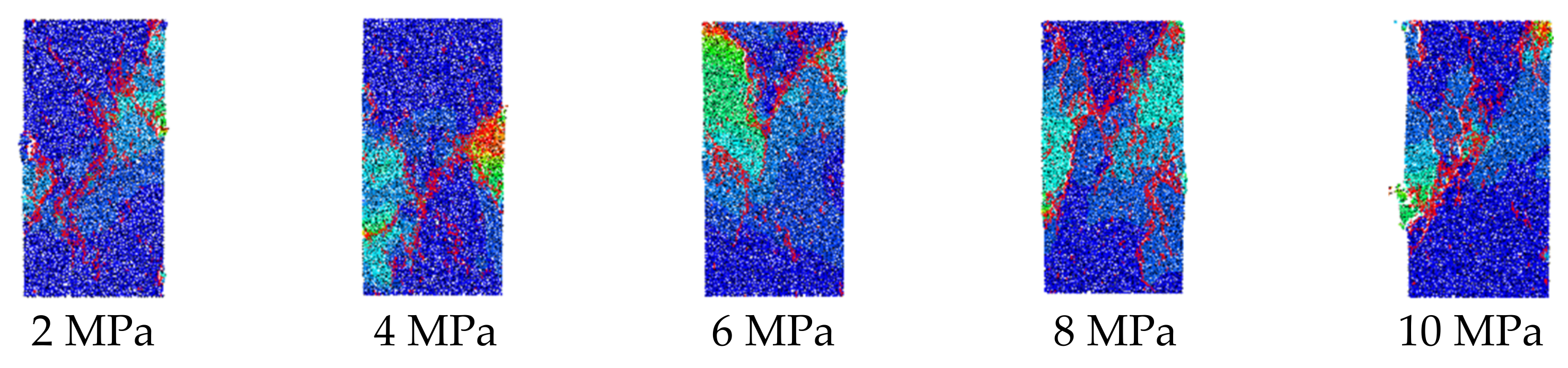
As shown in
Figure 14 and
Figure 15, when the curing pressure increased from 2 MPa to 10 MPa, the number of cracks at the loading end increased. When the curing pressure was relatively small, the compaction of the grout slurry was relatively low, and numerous pores were found among the particles. Under the loading effect, the pores were compressed, and elastic deformation occurred. When the local loads were higher than the bonding force of the particles, some microseparation fractures developed. As the loading process continued, fractures propagated and extended gradually, and the grout slurry finally failed. When the curing pressure was relatively high, the stress concentration at the ends was in accordance with Saint-Venant’s principle. When the pressure was higher than the bonding force among the particles, microcracks developed. Given that the strength of the stone powder-cement grout slurry was higher than that of the clay-cement grout slurry, microcracks concentrated at the upper parts of the clay-cement slurry grouting specimens and the lower parts of the stone powder-cement slurry grouting specimens. In the loading process, microcracks propagated and extended gradually to form run-through cracks. Tensile failure along the oblique section developed.
Failures were developed in the middle of the clay-cement grout slurry and the stone powder-cement grout slurry specimens, accompanied with local stress concentration. When loads were higher than the bonding force among the particles, several microcracks were produced, which propagated and extended gradually, showing “scissors-like” shapes. Finally, the specimens developed tensile failures.
3.4. Evolution Laws of Strength and Cracks of Slurry Grouting Materials
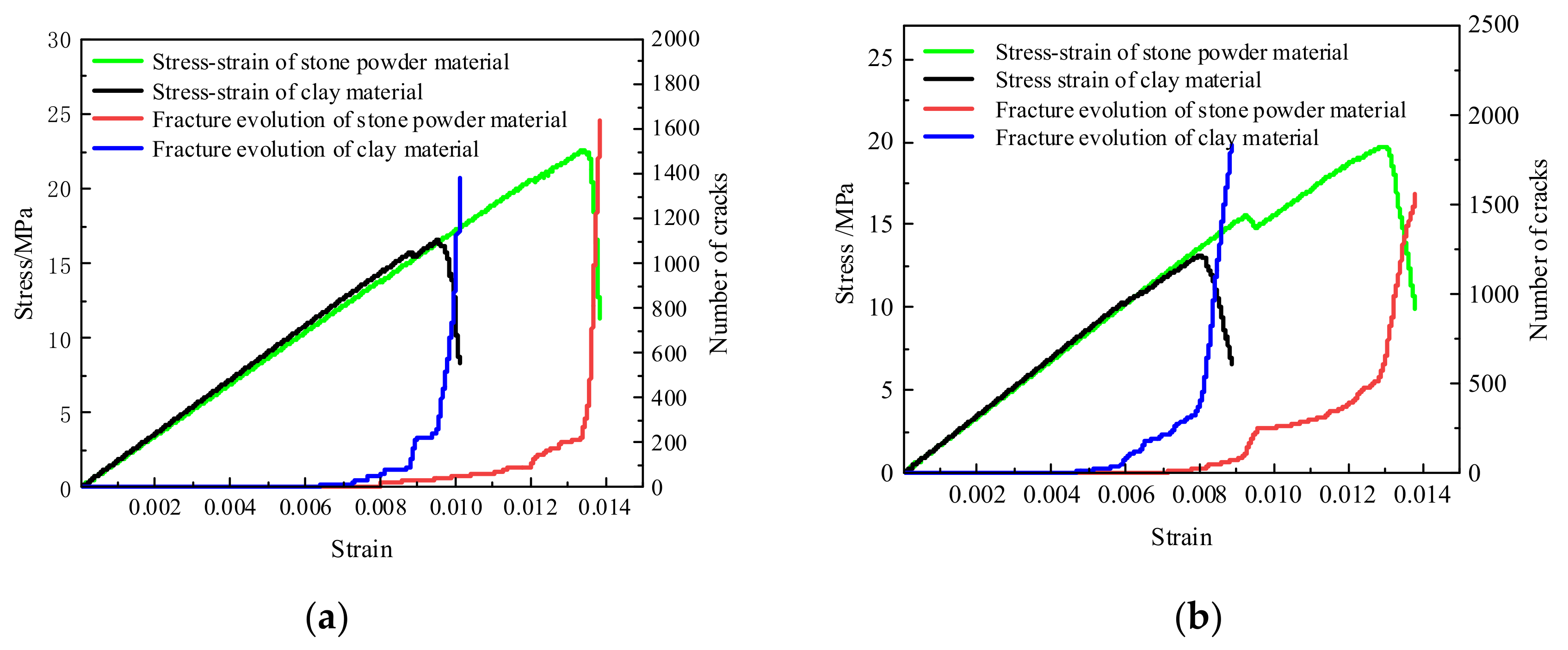
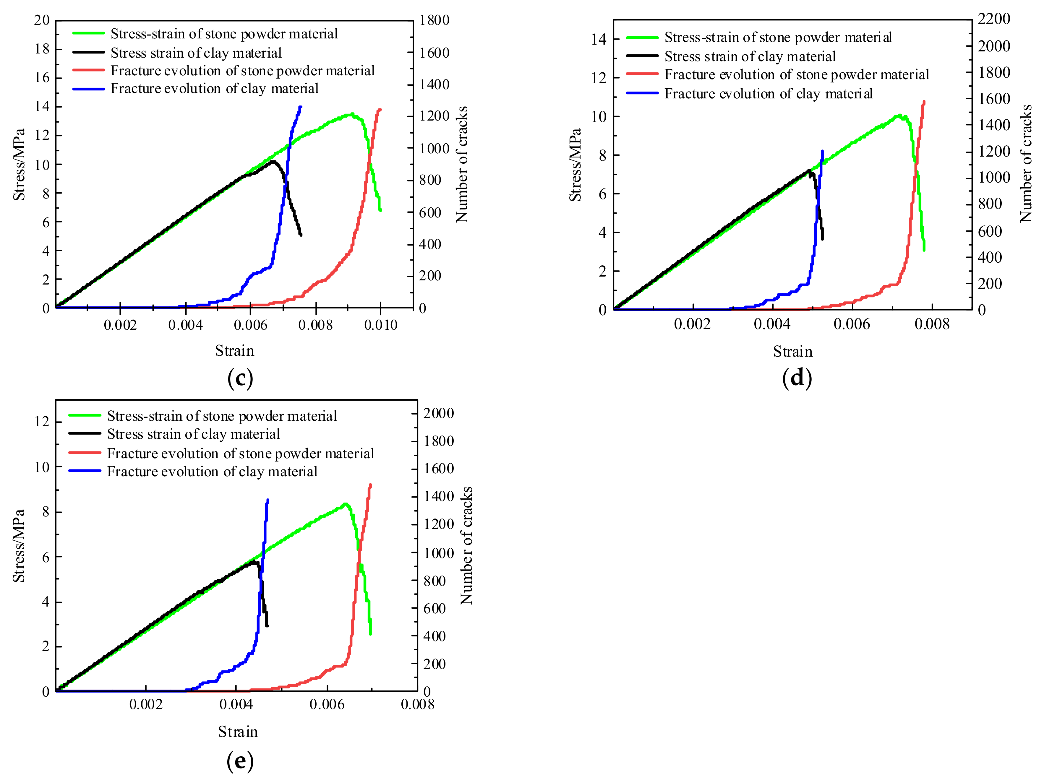
As shown in
Figure 16, under the same curing pressure, the stone powder-cement slurry presented higher stress and strain than the clay-cement slurry. As the curing pressure increased from 2 MPa to 10 MPa, the stress of the stone powder increased from 8.32 MPa to 22.58 MPa, and the strain increased from 0.006 to 0.013. The stress of the clay increased from 5.80 MPa to 16.55 MPa, and the strain increased from 0.0044 to 0.0095.
The failure process of both materials experienced the continuous elastic stage, crack propagation stage, and strength failure stage. The continuous elastic stage was influenced by external forces, and the internal pores were compressed in this stage, manifested as the positive relation between strain and stress, without crack generation. It can be viewed as the ideal elastic material. In the crack propagation stage, the crack quantity increased with the increase in stress, and the growth rate of strength was higher than that of the crack quantity. Moreover, the duration time of the elastic stage of the stone powder was longer than that of the clay, indicating that the stone powder could absorb more energy during resistance of external loads. In this stage, the cracks were mainly concentrated at the two ends of the specimens with the generation of tensile cracks. The grout slurry was in a stable stage, and it could resist external forces. In the strength failure stage, after reaching the strength peak, the crack quantity presented exponential growth, while stress dropped sharply. Microcracks continued to develop toward the middle area of the specimens and increased in quantity. The total cracks were within 1200–1600 in the stone powder and 1200–1700 in the clay. Finally, the stress concentration occurred among the particles. The bonding forces among the particles were destroyed, and microcracks gradually formed into a major crack. In this stage, the specimens were in the buckling stage and developed tensile failure.
This section may be divided by subheadings. It should provide a concise and precise description of the experimental results, their interpretation, as well as the experimental conclusions that can be drawn.
4. Conclusions
(1) With the increase in curing pressure, water drainage from the slurry increases, pore water pressure dissipates, and pores among the particles are compacted tightly. Moreover, resistance against water molecule permeation increases, contact force among particle skeletons is strengthened, stress-bearing structure of slurry improves, and strength of the grout slurry increases.
(2) Clay has water retention and hydrophilicity; thus, under the same curing pressure, the drainage resistance of the clay-cement slurry is larger than that of the stone powder-cement slurry, which causes the drainage of the stone powder-cement slurry to be larger than that of the clay-cement slurry. Moreover, the change law of dewatering water with time under the action of curing pressure conforms to the law of quadratic function. Among them, the fitting coefficient of the stone powder-cement slurry drainage function is 0.989, and the fitting coefficient of the clay-cement slurry drainage function is 0.997.
(3) The compressive strength of the stone powder-cement and the clay-cement slurry stone body under the double-height environment increases with the increase of the curing pressure. When the curing pressure increases from 2 MPa to 10 MPa, the compressive strength of the stone powder-cement slurry stone body increases from 8.3 MPa to 22.7 MPa, an increase of nearly 2.7 times. The compressive strength of the clay-cement slurry stone body increased from 5.7 MPa to 16.8 MPa, an increase of 2.9 times. Through polynomial fitting, the fitting coefficient of the stone powder-cement slurry is 0.979, and the fitting coefficient of the clay-cement slurry is 0.998. The degree of fitting is high. The relationship between the compressive strength of the stone body of the grouting material and the curing pressure conforms to a univariate quadratic function.
(4) Both grout slurry materials experience the continuous elastic stage, crack propagation stage, and strength failure in the whole failure process. The crack quantity is positively related to the curing pressure at failure of the grout slurry. Before the stress peak, some tensile cracks are initiated and developed slowly. After the stress peak, cracks propagate and extend quickly. The crack quantity presents exponential growth, forming a major crack that runs through the whole specimen. Finally, the specimens fail.
Author Contributions
Conceptualization, X.C. and L.Y.; methodology, Y.R.; formal analysis, Y.R.; investigation, Y.R., H.J. and X.C.; writing—original draft preparation, Y.R.; writing—review and editing, H.Z., X.C. and W.Z. All authors have read and agreed to the published version of the manuscript.
Funding
This research was funded by the National Natural Science Foundation of China (grant number 51834001), Henan Province Key R&D and Promotion Special (Science and Technology) Project (grant numbers 212102310107 and 212102310602), and National Natural Science Foundation of China (grant number (52104129)).
Institutional Review Board Statement
Not applicable.
Informed Consent Statement
Not applicable.
Data Availability Statement
Not applicable.
Acknowledgments
Thank you, Xinming Chen, Huazhe Jiao and Liuhua Yang for their guidance and funding, Haowen Zhang and Wenxiang Zhang for helping with the experimental paper, and your academic guidance and valuable suggestions.
Conflicts of Interest
The authors declare no conflict of interest.
References
- Liu, J.; Li, P.; Shi, L.; Fan, J.; Kou, X.; Huang, D. Spatial distribution model of the filling and diffusion pressure of synchronous grouting in a quasi-rectangular shield and its experimental verification. Undergr. Space 2021, 6, 650–664. [Google Scholar] [CrossRef]
- Seo, H.-J.; Choi, H.; Lee, I.-M. Numerical and experimental investigation of pillar reinforcement with pressurized grouting and pre-stress. Tunn. Undergr. Space Technol. 2016, 54, 135–144. [Google Scholar] [CrossRef]
- Zhou, Z.; Du, X.; Wang, S.; Zang, H. Analysis and engineering application investigation of multiple-hole grouting injections into porous media considering filtration effects. Constr. Build. Mater. 2018, 186, 871–883. [Google Scholar] [CrossRef]
- Mm, A.; Ea, B. Strength and permeability of boric acid-tempered ultrafine cement grouted sand. Constr. Build. Mater. 2021, 284, 122812. [Google Scholar]
- Rafi, J.; Stille, H. A method for determining grouting pressure and stop criteria to control grout spread distance and fracture dilation. Tunn. Undergr. Space Technol. 2021, 112, 103885. [Google Scholar] [CrossRef]
- Zhang, E.; Xu, Y.; Fei, Y.; Shen, X.; Zhao, L.; Huang, L. Influence of the dominant fracture and slurry viscosity on the slurry diffusion law in fractured aquifers. Int. J. Rock Mech. Min. 2021, 141, 104731. [Google Scholar] [CrossRef]
- Liu, X.; Wang, F.; Huang, J.; Wang, S.; Zhang, Z.; Nawnit, K. Grout diffusion in silty fine sand stratum with high groundwater level for tunnel construction. Tunn. Undergr. Space Technol. 2019, 93, 103051. [Google Scholar] [CrossRef]
- Zhang, Z.M.; Zou, J.; He, J.Y.; Wang, H.Q. Laboratory tests on compaction grouting and fracture grouting of clay. Chin. J. Geotech. Eng. 2009, 29, 186–192. [Google Scholar]
- Li, G.; Ma, F.; Guo, J.; Zhao, H.; Liu, G. Study on deformation failure mechanism and support technology of deep soft rock roadway. Eng. Geol. 2019, 264, 105262. [Google Scholar] [CrossRef]
- Jiao, H.; Wu, Y.; Wang, H.; Chen, X.; Li, Z.; Wang, Y.; Zhang, B.; Liu, J. Micro-scale mechanism of sealed water seepage and thickening from tailings bed in rake shearing thickener. Miner. Eng. 2021, 173, 107043. [Google Scholar] [CrossRef]
- Chen, F.; Xu, B.; Jiao, H.; Chen, X.; Shi, Y.; Wang, J.; Li, Z. Triaxial mechanical properties and microstructure visualization of BFRC. Constr. Build. Mater. 2021, 278, 122275. [Google Scholar] [CrossRef]
- Jiang, L.; Yang, C.; Jiao, H. Ultimately exposed roof area prediction of bauxite deposit goaf based on macro joint damage. Int. J. Min. Sci. Technol. 2020, 30, 699–704. [Google Scholar] [CrossRef]
- Jiao, H.; Wang, S.; Yang, Y.; Chen, X. Water recovery improvement by shearing of gravity-thickened tailings for cemented paste backfill. J. Clean. Prod. 2020, 245, 118882. [Google Scholar]
- Jiao, H.Z.; Wang, S.F.; Jia, T.R.; Ju, Y.W. Pore Structure Characterization of Tailing Bed and Dewatering Mechanism at nm-m Scales Under Shearing. J. Nanosci. Nanotechnol. 2021, 21, 354–361. [Google Scholar] [CrossRef]
- Jiao, H.-Z.; Wang, S.-F.; Wu, A.-X.; Shen, H.-M.; Wang, J.-D. Cementitious property of NaAlO_2-activated Ge slag as cement supplement. Int. J. Miner. Metall. Mater. 2019, 26, 1594–1603. [Google Scholar] [CrossRef]
- Jiao, H.; Wu, Y.; Wang, W.; Chen, X.; Wang, Y.; Liu, J.; Feng, W. The Micro-Scale Mechanism of Metal Mine Tailings Thickening Concentration Improved by Shearing in Gravity Thickener. J. Renew. Mater. 2021, 9, 14. [Google Scholar] [CrossRef]
- Jiang, L.; Lai, X.; Jiao, H. Concrete relative velocity prediction to prevent mortar segregation for safe gravity transportation. Alex. Eng. J. 2020, 59, 5155–5164. [Google Scholar] [CrossRef]
- Chen, X.; Jin, X.; Jiao, H.; Yang, Y.; Liu, J. Pore connectivity and dewatering mechanism of tailings bed in raking deep-cone thickener process. Minerals 2020, 10, 375. [Google Scholar] [CrossRef]
- Yang, Y.; Zhao, T.; Jiao, H.; Wang, Y.; Li, H. Potential effect of porosity evolution of cemented paste backfill on selective solidification of heavy metal ions. Int. J. Environ. Res. Public Health 2020, 17, 814. [Google Scholar] [CrossRef]
- Vardhan, K.; Goyal, S.; Siddique, R.; Singh, M. Mechanical properties and microstructural analysis of cement mortar incorporating marble powder as partial replacement of cement. Constr. Build. Mater. 2015, 96, 615–621. [Google Scholar] [CrossRef]
- Campos, H.F.; Klein, N.S.; Filho, J.M.; Bianchin, M. Low-cement high-strength concrete with partial replacement of Portland cement with stone powder and silica fume designed by particle packing optimization. J. Clean Prod. 2020, 261, 121228. [Google Scholar] [CrossRef]
- Aliabdo, A.A.; Elmoaty, A.; Auda, E.M. Re-use of waste marble dust in the production of cement and concrete. Constr. Build. Mater. 2014, 50, 28–41. [Google Scholar] [CrossRef]
- Medina, G.; del Bosque, I.F.S.; Fríasc, M.; de Rojas, M.I.S.; Medina, C. Durability of new recycled granite quarry dust-bearing cements. Constr. Build. Mater. 2018, 187, 414–425. [Google Scholar] [CrossRef]
- Lemaire, K.; Deneele, D.; Bonnet, S.; Legret, M. Effects of lime and cement treatment on the physicochemical, microstructural and mechanical characteristics of a plastic silt. Eng. Geol. 2013, 166, 255–261. [Google Scholar] [CrossRef]
- Belaidi, A.; Azzouz, L.; Kadri, E.; Kenai, S. Effect of natural pozzolana and marble powder on the properties of self-compacting concrete. Constr. Build. Mater. 2012, 31, 251–257. [Google Scholar] [CrossRef]
- Erguen, A. Effects of the usage of diatomite and waste marble powder as partial replacement of cement on the mechanical properties of concrete. Constr. Build. Mater. 2011, 25, 806–812. [Google Scholar] [CrossRef]
- Bayesteh, H.; Sharifi, M. Effect of stone powder on the rheological and mechanical performance of cement-stabilized marine clay/sand. Constr. Build. Mater. 2020, 262, 120792. [Google Scholar] [CrossRef]
- Yahia, A.; Tanimura, M.; Shimoyama, Y. Rheological properties of highly flowable mortar containing limestone filler-effect of powder content and W/C ratio. Cem. Concr. Res. 2005, 35, 532–539. [Google Scholar] [CrossRef]
- Zhang, S.; Fan, Y.; Huang, J.; Shah, S.P. Effect of nano-metakaolinite clay on the performance of cement-based materials at early curing age. Constr. Build. Mater. 2021, 291, 123107. [Google Scholar] [CrossRef]
- Güneyisi, E.; Gesoğlu, M.; Mermerdaş, K. Improving strength, drying shrinkage, and pore structure of concrete using metakaolin. Constr. Build. Mater. 2008, 41, 937–949. [Google Scholar] [CrossRef]
- Junan, S.; Xie, Z.X.; Griggs, D.; Shi, Y.Z. Effects of Kaolin on Engineering Properties of Portland Cement Concrete. Appl. Mech. Mater. 2012, 174, 76–81. [Google Scholar]
- Yazc, E.; Arel, H.Ş.; Anuk, D. Influences of Metakaolin on the Durability and Mechanical Properties of Mortars. Arab. J. Sci. Eng. 2014, 39, 8585–8592. [Google Scholar]
- Arslan, F.; Benli, A.; Karatas, M. Effect of high temperature on the performance of self-compacting mortars produced with calcined kaolin and metakaolin—ScienceDirect. Constr. Build. Mater. 2020, 256, 119497. [Google Scholar] [CrossRef]
- Karatas, M.; Benli, A.; Arslan, F. The effects of kaolin and calcined kaolin on the durability and mechanical properties of self-compacting mortars subjected to high temperatures. Constr. Build. Mater. 2020, 265, 120300. [Google Scholar] [CrossRef]
- Chen, S.; Wang, W.; Wu, A.; Wang, Y. Analysis of influencing laws and mechanism of curing pressure on paste filling strength. Chin. J. Nonferrous Met. 2021, 31, 3740–3749. [Google Scholar]
- Gong, G. Research on Cylinder Filtering and Dehydration Mechanism of Fine Clean Coal; China University of Mining and Technology, 2011. Available online: https://kns.cnki.net/kcms/detail/detail.aspx?dbcode=CDFD&dbname=CDFD0911&filename=1011281101.nh&uniplatform=NZKPT&v=k2i1Wh6soydEdahE3HChUCNN8gD8Fd5Hd4BB8lvR7aDt9_ETyW3jAeQq4iV_GXMQ (accessed on 20 March 2022).
- Lv, S.; Qi, C.; Mo, D. Principles of Chemical Engineering; Chemical Industry Press: Beijing, China, 2015. [Google Scholar]
Figure 1.
Simple model of double-high curing device.
Figure 1.
Simple model of double-high curing device.
Figure 4.
Principle and model of double-high curing device: (a) principle of double-high curing device; (b) model of double-high curing device; (a) 1—pressure lever; 2—rubber stropper; 3—slurry tank; 4—curing pressure slurry; 5—bolt; 6—drain hole; 7—filter cloth; 8—base; (b) 1—Pressure lever; 2—slurry tank; 3—bolt; 4—filter cloth; 5—base.
Figure 5.
Raw material samples and micrograms: (a) clay materials and microgram; (b) stone powder and microgram; (c) cement and microgram.
Figure 5.
Raw material samples and micrograms: (a) clay materials and microgram; (b) stone powder and microgram; (c) cement and microgram.
Figure 6.
Particle size distribution curves of clay and stone powder.
Figure 6.
Particle size distribution curves of clay and stone powder.
Figure 7.
Test process of filter cake specimens: (a) curing pressure process; (b) demolding of filter cake; (c) drilling sampling; (d) cylinder specimens.
Figure 7.
Test process of filter cake specimens: (a) curing pressure process; (b) demolding of filter cake; (c) drilling sampling; (d) cylinder specimens.
Figure 8.
Modeling pressure resistance process: (a) generation model of surrounding wall constraints; (b) upper and lower wall constraint loading.
Figure 8.
Modeling pressure resistance process: (a) generation model of surrounding wall constraints; (b) upper and lower wall constraint loading.
Figure 9.
Microstructures of grout slurry under different curing pressures: (a) clay-cement grout slurry; (b) stone powder-cement grout slurry.
Figure 9.
Microstructures of grout slurry under different curing pressures: (a) clay-cement grout slurry; (b) stone powder-cement grout slurry.
Figure 10.
Influencing mechanism of curing pressure on strength of clay-cement slurry: (a) 2 MPa; (b) 4 MPa; (c) 8 MPa.
Figure 10.
Influencing mechanism of curing pressure on strength of clay-cement slurry: (a) 2 MPa; (b) 4 MPa; (c) 8 MPa.
Figure 11.
Influencing mechanism of curing pressure on strength of stone powder-cement slurry: (a) 4 MPa; (b) 4 MPa; (c) 8 MPa.
Figure 11.
Influencing mechanism of curing pressure on strength of stone powder-cement slurry: (a) 4 MPa; (b) 4 MPa; (c) 8 MPa.
Figure 12.
Relation curves of water drainage from the slurry with time.
Figure 12.
Relation curves of water drainage from the slurry with time.
Figure 13.
Relations between curing pressure and compressive strength.
Figure 13.
Relations between curing pressure and compressive strength.
Figure 14.
Crack diagrams of the clay-cement grout slurry under different curing pressures.
Figure 14.
Crack diagrams of the clay-cement grout slurry under different curing pressures.
Figure 15.
Crack diagrams of the stone powder-cement grout slurry under different curing pressures.
Figure 15.
Crack diagrams of the stone powder-cement grout slurry under different curing pressures.
Figure 16.
Stress-strain curves and crack evolution of different materials. (a) Curing pressure = 10 Mpa. (b) Curing pressure = 8 Mpa. (c) Curing pressure = 6 Mpa. (d) Curing pressure = 4 Mpa. (e) Curing pressure = 2 Mpa.
Figure 16.
Stress-strain curves and crack evolution of different materials. (a) Curing pressure = 10 Mpa. (b) Curing pressure = 8 Mpa. (c) Curing pressure = 6 Mpa. (d) Curing pressure = 4 Mpa. (e) Curing pressure = 2 Mpa.
Table 1.
Major chemical composition of stone powder (%).
Table 1.
Major chemical composition of stone powder (%).
| Others | CaO | SiO2 | AL2O3 | MgO | Others |
|---|
| Percentage (%) | 43.00 | 15.72 | 3.14 | 1.18 | 36.96 |
Table 2.
Major chemical components of cement (%).
Table 2.
Major chemical components of cement (%).
| Others | SiO2 | AL2O3 | CaO | Fe2O3 | MgO | Others |
|---|
| Percentage (%) | 20.61 | 3.98 | 65.70 | 2.62 | 1.56 | 5.53 |
Table 3.
Mixing ratio of grouting materials.
Table 3.
Mixing ratio of grouting materials.
| Grouting Materials | Fluidity/cm | Stone Powder/g | Clay/g | Cement/g | Water/g |
|---|
| Clay-cement slurry | 29.6 | — | 720 | 240 | 864 |
| Stone powder-cement slurry | 29.6 | 720 | — | 240 | 971 |
Table 4.
Meso-structure parameters of particles.
Table 4.
Meso-structure parameters of particles.
| Specimen No. | Contact Modulus/GPa | Contact Rigidity/GPa | Parallel Cementation Modulus/GPa | Normal Cementation Strength/MPa | Tangential Cementation Strength/MPa | Friction Factor | Compressive Strength/MPa |
|---|
| Stone powder-cement material | 1 | 10 | 1 | 10 | 11 | 11 | 0.3 | 21.70 |
| 2 | 10 | 1 | 10 | 9.9 | 9.9 | 0.3 | 19.70 |
| 3 | 10 | 1 | 10 | 7 | 7.0 | 0.3 | 13.50 |
| 4 | 10 | 1 | 10 | 5.3 | 5.3 | 0.3 | 10.07 |
| 5 | 10 | 1 | 10 | 3.7 | 3.7 | 0.3 | 8.38 |
| Clay-cement material | 6 | 8 | 0.83 | 9 | 9.7 | 9.7 | 0.4 | 16.55 |
| 7 | 8 | 0.83 | 9 | 7.6 | 7.6 | 0.4 | 13.15 |
| 8 | 8 | 0.83 | 9 | 5.2 | 5.2 | 0.4 | 10.20 |
| 9 | 8 | 0.83 | 9 | 3.7 | 3.7 | 0.4 | 7.22 |
| 10 | 8 | 0.83 | 9 | 2.1 | 2.1 | 0.4 | 5.80 |
| Publisher’s Note: MDPI stays neutral with regard to jurisdictional claims in published maps and institutional affiliations. |
© 2022 by the authors. Licensee MDPI, Basel, Switzerland. This article is an open access article distributed under the terms and conditions of the Creative Commons Attribution (CC BY) license (https://creativecommons.org/licenses/by/4.0/).


 ,
, 


