1. Introduction
Timber-to-concrete composite (TCC) system
s with screws have become since the 1980s a widespread solution for floor-building and retrofitting, representing an option to the typical “timber plank” additional layer [
1].
The framework of a generic TCC floor consists of a thin concrete layer overlapping timber beams mutually joined with steel fasteners (i.e., dowels, plates and screws). These can be fully or partially threaded and can be placed perpendicularly to the floor or inclined at an angle. The high efficiency of this solution compared to traditional floors lies in: (i) increased strength and stiffness, (ii) excellent acoustic/thermal insulation, (iii) improved fire resistance [
2,
3,
4], (iv) capacity to reduce the sensitivity to vibrations, (v) horizontal diaphragms for structures and (vi) redistribution of more than 50% of a concentrated load to the nearest joists [
5]. The overall behaviour of a composite TTC floor is mostly influenced by the interaction between timber, concrete and screws. Timber is installed in the tensile zone, the thin concrete layer in the compression zone, while the screws, which transfer the internal actions between the two members, are mainly subjected to shear stresses. A combination of shear and tensile forces develops into the screws if they are inclined. To guarantee the applicability of the section analysis, no slip should occur at the interface of load-bearing elements, and the shear connectors should be sufficiently stiff. However, a certain relative slip between concrete and timber is often present, and this phenomenon should be properly taken into account in the design process [
6]. Most importantly, for accurate structural design calculations, the partial interaction between members should be accounted for when calculating the equivalent bending stiffness, the maximum stresses in each component and the maximum forces in the fasteners [
7]. In most cases, however, the design process is regulated by short-term and long-term deformability checks only. A hybrid multiscale-based material model–standardized structural analysis method could be thus used for the analysis of TCC floor–creep behaviour [
8].
The connection system is a fundamental part of TCC structures, and thus different types of connectors have been proposed and studied in recent years. Ceccotti [
9] proposed a stiffness classification index by selecting the most common ones. In that study, he emphasized in particular that dowel-type fasteners (i.e., nails, screws and dowels) are less rigid than surface connectors, while the notched elements with connectors are less stiff than those with glued interfaces. Compared to other fasteners, screws have the advantage of being easily available and also easy to install [
10].
Long threaded screws have been used for fastening and reinforcement interventions in recent years. Traditionally, screw fasteners have been typically placed perpendicular to the sliding interface plane. In such a configuration, the relative sliding between the timber beam and the concrete slab is mostly contrasted by the bending stiffness of the screw fastener and thus results in a relatively low slip modulus for the TCC system. The configurations with inclined screws, on the other hand, make possible the load transfer to the timber element, even along the axial direction, to take the most advantage of the generally high tensile capacity of screws. However, by reducing the angle between the screw and the shear plane, installation difficulties arise especially for extreme inclination angles, and an inclination of 45° represents a balanced solution between mechanical performance/capacity and ease of application in practice [
11]. Overall, under a given geometric and loading condition, TCC floor configurations with inclined screws require a smaller number of connectors compared to those with perpendicular screws.
Several experimental tests and analytical formulations have been thus carried out to assess the load-carrying behaviour of screws for TCC solutions in different configurations. Among others, an interesting comparison has been proposed in terms of single-inclination screws and inclined cross-screws subjected to shear stress forces. Steinberg et al. [
12] performed push-out tests with lightweight concrete slabs and different screw configurations, proving that the shear stiffness of inclined cross screws is significantly higher than a single-inclined screw. Kavaliauskas et al. [
13] evaluated the possible use of Johansen’s yield theory to estimate the ultimate load for TCC floors using self-tapping threaded screws at a given angle to timber-concrete interface. Bedon and Fragiacomo [
14] proposed an extended FE numerical model to reconstruct the general mechanical behaviour of notched connections for TCC beams and floor components. The main purpose was to reproduce the failure mechanisms of push-out specimens made of steel, concrete and timber, giving evidence of screw arrangements and their effects on local and global mechanical performances, including damage. Other FE numerical analyses were developed by Sciomenta et al. [
15], in order to understand how different concrete types (and especially Rubbercrete instead of ordinary concrete) and inclination angles could modify the connector load-bearing capacity.
In the last years, rather few authors have investigated the influence of the interlayer which is commonly placed between the timber element and the concrete slab, and more precisely its effect on the overall load-bearing capacity. This layout represents the typical structural situation in which timber reinforcing elements are positioned on existing flooring, as for example happens in common practice for most retrofit interventions. Van Der Linden [
16], in this regard, investigated the effect of an OSB (Oriented Strand Board) interlayer with screws and observed a decrease of 50% on the slip modulus for the TCC system, compared to the configuration without an interposed OSB interlayer. Jorge et al. [
17] carried out a set of experimental tests accounting for the presence of a timber interlayer in a conventional push-out setup, for specimens made of normal-weight concrete (NWC) as well as of lightweight concrete (LWAC). In the set of specimens made of NWC, for example, it was observed that the interlayer inclusion leads to an average reduction of 30% and 50% for the load-bearing capacity and slip modulus, respectively. In the set of specimens made by LWAC, in contrast, it was found that such a reduction falls to 10% and 30%, respectively.
The effect of a plywood interlayer coupled with self-compacting concrete (SCC) and SFS screws was investigated by Moshiri et al. [
18]. Through that experimental campaign, the undesirable effect of interlayer on strength and stiffness was confirmed overall. A significant reduction of both the serviceability and ultimate slip moduli (ranging 20–40%) was also experimentally observed. The influence of an interlayer on mechanical properties of TCC structures using threaded rebars as shear connectors was finally studied in [
19], and also in this case the experimental evidences highlighted a modification in shear strength and stiffness of TCC connections. In terms of modelling, a mathematical model capable of estimating the slip modulus of TCC systems was developed in [
20], so as to take into account also its dependency upon the screw inclination and the interlayer flooring thickness. In [
21], the same mathematical model was further elaborated and extended, confirming the limitation of inclined screws in terms of slip modulus, due to the weakness of the timber interlayer. Recently, two new analytical models have been proposed in [
10,
22] for the slip modulus prediction of connections with inclined screws in TCC systems. Their main advantage is the capacity of accounting for sound insulation [
22] and timber board interlayer [
10], respectively. In both cases, it is shown that the concrete thickness has no influence on the connection stiffness, and the interlayer has a negative impact.
In this paper, a set of FE parametric analyses is carried out on TCC connections with inclined screws and an OSB interlayer. A novel approach is proposed to efficiently calibrate the mechanical properties of connection material components, with specific evidence of the cohesive contact between the screw and the surrounding wooden element. Under these working assumptions, a parametric investigation focused on the interlayer influence on TCC load-bearing capacity is thus presented. To this aim, preliminary FE analyses are first validated based on former push-out experimental results [
20]. Successively, different screw inclinations, as well as thicknesses and mechanical properties for the interlayer, are taken into account. The influence of interaction type and features on the sliding plane, as well as the test setup (i.e., direct shear, push-out or inclined shear), are also examined and quantified in terms of mechanical performance indicators for the examined TCC connections.
2. Background Experiments
An experimental campaign was carried out to assess and quantify the influence of the in-between interlayer, as well as the role of the screw length, on the basic mechanical performance indicators of inclined screw connections commonly used in TCC floors.
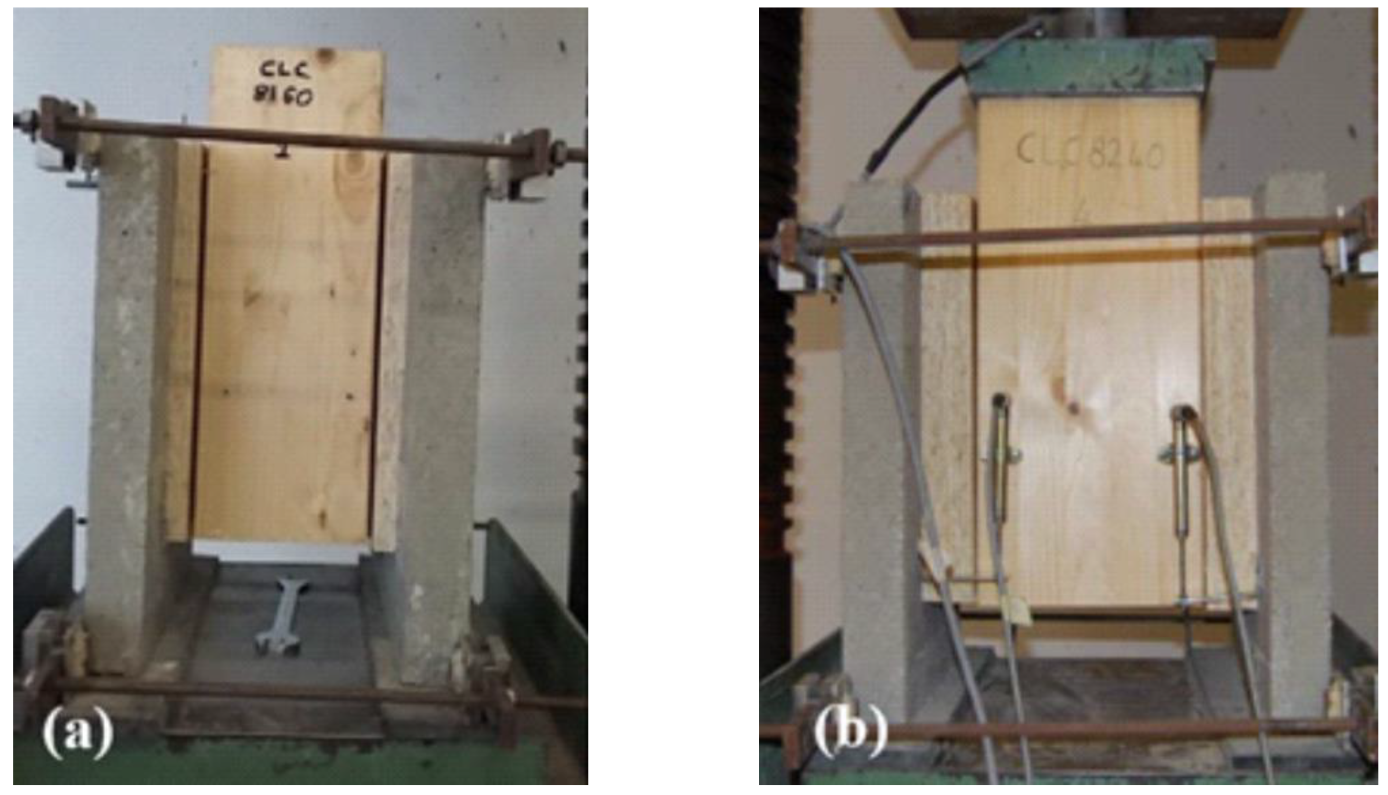
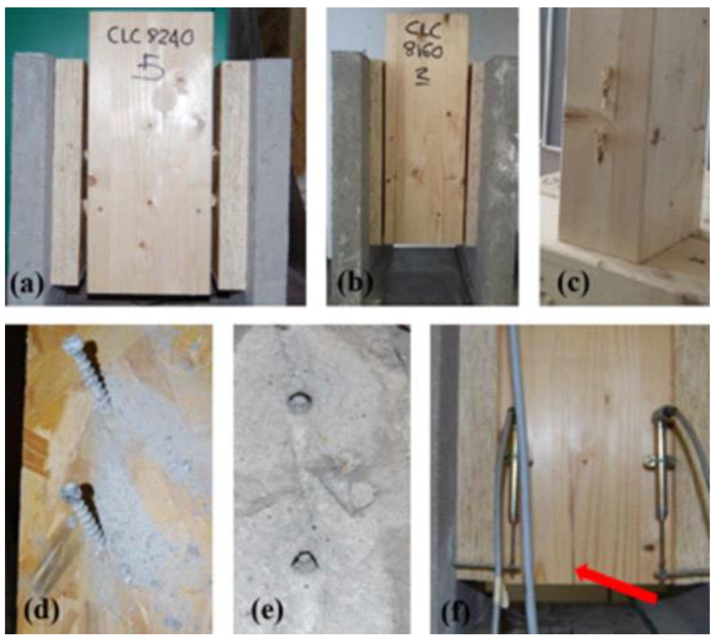
A total of twenty push-out tests were investigated in [
20], with specimens divided into two main groups, namely “clc8160” and “clc8240” series, in which the samples differed in geometrical features, as shown in
Figure 1. Both the groups were characterized by a symmetric configuration, consisting of an inner glue-laminated timber (glulam) element and two outer concrete slabs. The latter, made of concrete of strength class C25/30 according to Eurocode 2 [
23], were connected to the central glulam element, with strength class GL24h according to EN 14080:2013 [
24], by two fully threaded screws per side, at an inclination of 45°. Between the timber elements and the concrete ones, an OSB panel was thus interposed, acting as an existing floor panel or a disposable formwork in existing or new buildings, respectively. Regarding the fasteners and interlayers in use in the first group of specimens (clc8160), screws with a diameter
of 8 mm and a length
of 160 mm, and OSB panels with a thickness
of 22 mm, were taken into account (
Figure 1a). In the second group, clc8240, screws with the same diameter (8 mm) and a length of 240 mm, with 44 mm-thick OSB panels, were considered (
Figure 1b). The cross-section of concrete slabs of both groups were 50 mm by 500 mm, with a length of 450 mm. The glulam elements were 450 mm in length and 160 mm by 120 mm in cross-section for clc8160 samples, while the cross-section increased to 200 mm by 120 mm for clc8240 specimens.
All the tests were conducted in accordance with UNI EN 26891:1991 [
25], which describes the procedural stages of push-out protocol. After estimating
Fest, which represents the maximum load expected based on preliminary evaluations, the load was increased to 0.4
Fest and maintained for 30 s, then was decreased to 0.1
Fest and maintained for the same time period. Subsequently the load was increased further, until the failure of the specimen or a maximum deformation of 15 mm (whichever came first).
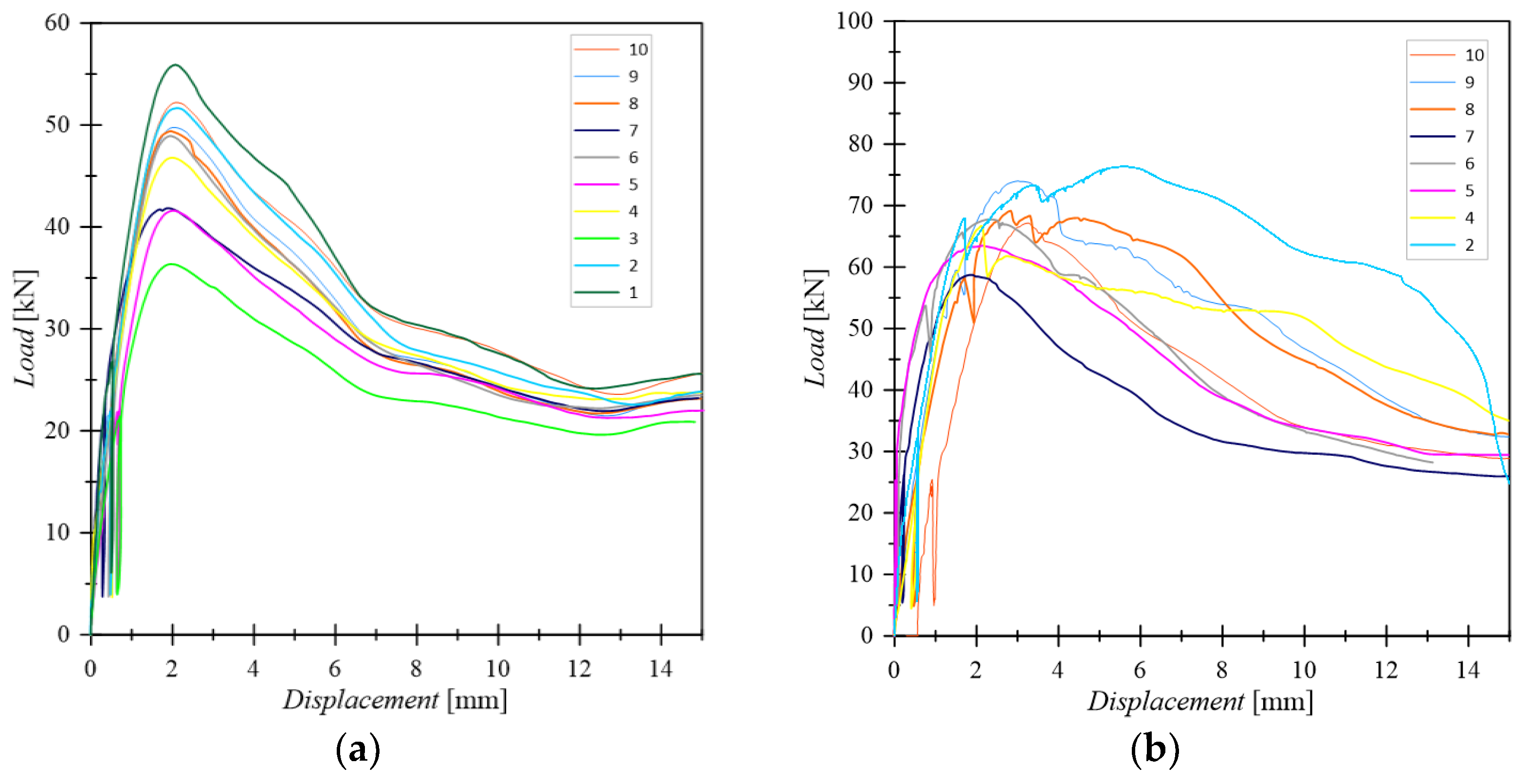
The relative slip between concrete and timber was measured with displacement transducers placed on both the interfaces. In addition, two metal rings were adopted in order to prevent the possible separation of the elements due to the load-reaction eccentricity. Finally, all the tests were conducted by load control, and the displacements were recorded versus the total applied load, allowing the typical load-displacement curves to be obtained, as displayed in
Figure 2. Relevant specimen data and results are given in
Table 1,
Table 2 and
Table 3.
3. FE Numerical Investigation
3.1. Modelling Assumptions
The experimental tests were reproduced by FE numerical models implemented in the ABAQUS software package [
26]. With the aim of investigating the influence of previously evidenced selected parameters, such as the interlayer mechanical properties and the interaction of the interlayer with the main load-bearing members, a modelling strategy based on three-dimensional solid brick elements was taken into account. Specifically, the effects of these parameters were investigated in terms of ultimate strength
, stiffness
and ultimate stiffness
for a given TCC connection.
The reference simulation consisted in a static incremental, geometrically linear, displacement-controlled analysis. Two planes of symmetry were taken into account for the experimental setup in
Figure 1, and this allowed modelling 1/4th of the nominal geometry for the reference specimen (see
Figure 3). More precisely, the glulam member, the concrete member, the interlayer and the screws were described with C3D8R elements, which represent a general-purpose linear brick element type, with reduced integration, and is available in the ABAQUS library.
At the preliminary stage, the complex geometry of the examined TCC systems required numerous mesh sensitivity studies. In order to obtain an accurate and computationally efficient FE model, the spatial domain of each member was divided into several subdomains, in order to allow the definition of transition zones between regions with extremely refined mesh patterns (i.e., close to screws) or with coarser mesh schemes. Overall, sensitivity studies showed that a mesh size of approximately ≈1 mm in proximity of screws and ≈5 mm in the terminal areas of specimens should be taken into account for similar systems. The resulting FE model consisted of a total of 200,000 solid brick elements with an aspect ratio less than 3.
To avoid the separation of TCC members during the loading stage, additional restraints, as in
Figure 1, were also taken into account in FE modelling. The effect of these retainers was modelled in the form of an additional translation constraint, which was applied to the concrete member base surface in the
x direction (
Figure 3). The displacements in the
y direction were also constrained on the two base-concrete contact surfaces. Overall, the modelling of 1/4
th of the nominal geometry also required the application of constraints for
on the
xy symmetry plane and
on the
yz symmetry plane, respectively.
3.2. Material Properties and Constitutive Models
The glulam GL24h member was mechanically described as a homogeneous orthotropic elastic-plastic material and its input properties were determined on the basis of product standards, technical specifications of the product and literature data [
25,
28]. In more detail, the moduli of elasticity parallel and perpendicular to grain were assumed as
N/mm
2 and
N/mm
2, respectively. The shear modulus and the rolling shear modulus were also quantified in
N/mm
2 and
N/mm
2, respectively. Poisson’s ratios for the local directions of interest were set to
, according to the extensive literature research in [
27] for softwoods.
To account for damage, an anisotropic yield was defined through Hill’s yield criterion. The strength values parallel and perpendicular to grain were assumed to be equal to N/mm2 and N/mm2. The shear strength and the rolling shear strength values were defined in N/mm2 and N/mm2, respectively.
The reference OSB panel that was used as interlayer can be described as an OSB/3 class, with a thickness between 18 and 25 mm and ρ = 600 kg/m
3 [
28,
29]. The corresponding mechanical properties were thus used for the definition of an orthotropic material. According to [
28], the elastic modulus and the strength in the main and secondary directions were assumed as
N/mm
2 and
N/mm
2 and
N/mm
2 and
N/mm
2. According to [
29], finally, the shear moduli and shear strength values were defined in
N/mm
2 and
N/mm
2,
N/mm
2 and
N/mm
2.
The experimental investigation summarized in
Section 2, for example, highlighted no significant crack on the concrete side for most specimens. Therefore, the concrete member was modelled as a homogeneous and isotropic elastic material with an elastic modulus defined in accordance with the strength class C25/30 of Eurocode 2 [
23], that is
N/mm
2 and:
The carbon steel screw was modelled with an elastic-plastic material law, with elastic modulus
N/mm
2 and yielding stress such as to guarantee the same yield moment declared in the ETA-19/0244 [
30], that is
N/mm
2.
Finally, a static friction coefficient of
and
, respectively, was adopted on the glulam-OSB and concrete-OSB shear planes, in accordance with previous outcomes from Air et al. [
31].
3.3. Screw-Members Interaction
Due to the complex geometry of the screw represented by the presence of the thread, as well as due to the state of combined shear and axial force that occurs when the screws are inclined with respect to the shear plane for TCC systems, it is necessary to pay particular attention to the modelling of the screw-member transition area.
An efficient modelling technique herein adopted for the mechanical description of the screw-glulam interaction mechanism was originally developed by Avez et al. [
32] and also applied in [
33] for the numerical analysis of similar timber-timber connections, as well as further adapted for localized analysis of bonded-in-rod (BiR) adhesive connections for timber [
34]. The technique consists in the use of a fictitious layer of deformable material (herein called “soft-layer”) in conjunction with a cohesive surface interaction with damage initiation and propagation criteria. In this way it is possible to take into account:
the high initial withdrawal stiffness guaranteed by the direct timber-screw interaction through the screw thread;
the progressive degradation of this interaction due to damage to the interface at the attainment of a limit stress;
the possibility of separation on the screw-timber interface;
the actual axial and flexural stiffness of the screw.
According to this recalled approach, the screw is described in the present study by a cylinder with a diameter equal to the inner thread diameter of the screw. In this way, the axial stiffness EA and flexural stiffness EI of the simplified geometry can be considered to be similar to those of a real fastener.
The gap between the cylinder representative of the screw shank and the surface external to the thread on which withdrawal failure occurs is then modelled by a hollow cylinder of extremely deformable material (“soft-layer”). Therefore, the soft-layer schematizes that area in which the thread and the damaged timber fibres coexist, and consequently this complex medium can only be approximated in a fictitious way by an orthotropic elastic material.
For the present investigation, the mechanical properties of the medium were defined with reference to the main directions of the cylinder (axial, radial and tangential directions in
Figure 4) and were assumed to coincide with those of glulam in the direction perpendicular to the fibres (
N/mm
2 and
N/mm
2). The chosen value of the elastic modulus in the axial direction of cylinder was calibrated in such a manner as not to affect the axial stiffness of the fastener (
N/mm
2).
A contact interaction with “normal-hard” mechanical behaviour was defined on the outer surface of the soft-layer, which avoids the interpenetration of the nodes of the glulam member and the nodes of the soft-layer without the possibility of transferring tensile stresses in the direction normal to the surface. In defining the cohesive contact, the stiffness and resistance in the normal direction (
N/mm
3,
N/mm
2) were set to zero, in order to allow free separation of the two surfaces. With these positions and considering a decoupled behaviour, the stiffness matrix of the interaction was hence reduced to:
with
,
and
,
being shear stress and displacements in the first (axial) and secondary tangential directions.
The MAXS damage initiation criterion was also reduced to:
with
and
being the shear resistance values for the cohesive contact in the two main directions.
Finally, a linear law for the evolution of damage was used with an ultimate displacement equal to 4 mm [
32]. A friction type interaction was added to the tangential interaction of the cohesive type, so that it could be progressively activated with the evolution of cohesive degradation and reproduce the timber-timber sliding after reaching the local breakage by withdrawal of the screw (
). A normal-hard and tangential-penalty type interaction was also assigned to the sliding surface between screw and OSB with (
), implicitly assuming a negligible withdrawal resistance in the interlayer and therefore considering the withdrawal prevented by friction between the damaged timber fibres only.
Considering the negligible frequency of withdrawal at concrete side failure in the experimental campaign of
Section 2, and with the intention of creating a FE model capable of capturing the average response of those experimental tests, the screw was considered perfectly bound to the concrete slab via a rigid “tie” constraint.
3.4. Model Updating
The use of the soft-layer and cohesive contact makes it possible to consider the screw-timber interaction in a simplified way, but introduces some parameters in the model that are not directly related to the physical characteristics of the modelled object. For the configurations reproduced, a direct dependence of the numerically determined stiffness and strength ( and ) on the stiffness and resistance of the cohesive contact in the longitudinal direction ( and ), respectively, was observed. Therefore, considering and as the parameters of the model characterized by greater uncertainty and having fixed all the other parameters as described in the previous paragraph, two independent optimizations were carried out.
With a gradient-based algorithm, an optimization of the average FE-experimental percentage deviation of the stiffness
of the two tested configurations (E1 = clc8160 and E2 = clc8240) was carried out. The function
to minimize as
varies can be defined by the following equation:
where
The stiffness of the cohesive contact for the iteration
was determined using the following equation:
With the same procedure, an optimization of the average FE-experimental percentage deviation of the
strength for the two tested TCC configurations was thus performed. The function
to minimize with
variations can be defined by the following equations:
Using as optimization stop criteria such as and , and assuming as learning rate , the two values able to make the FE models respond like the real systems were thus quantified in N/mm3 and N/mm2.
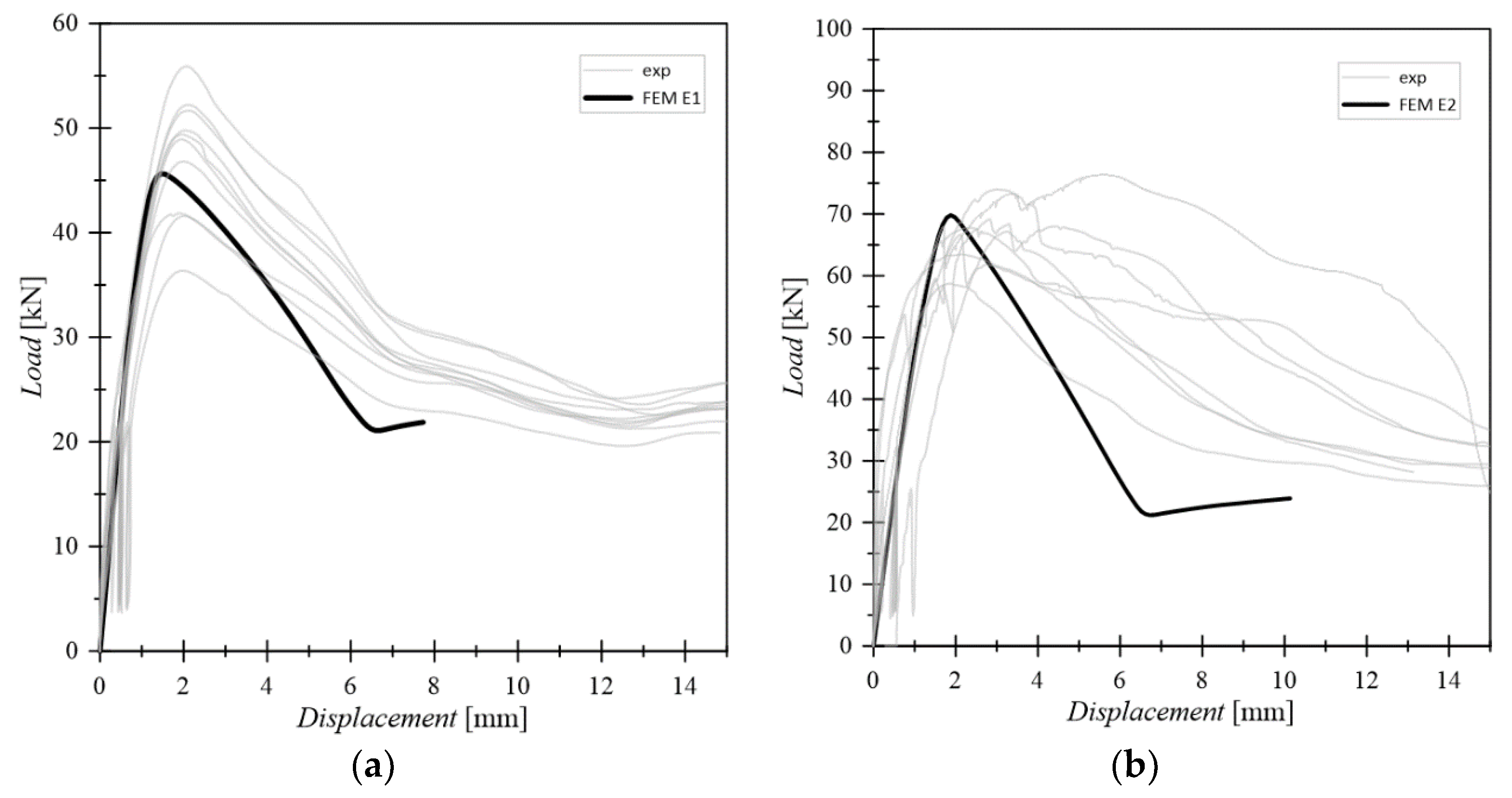
The so calibrated and updated FE models were found to be able to describe well the average experimental response in terms of force displacement curve (see
Figure 5) and also in terms of synthetic parameters (
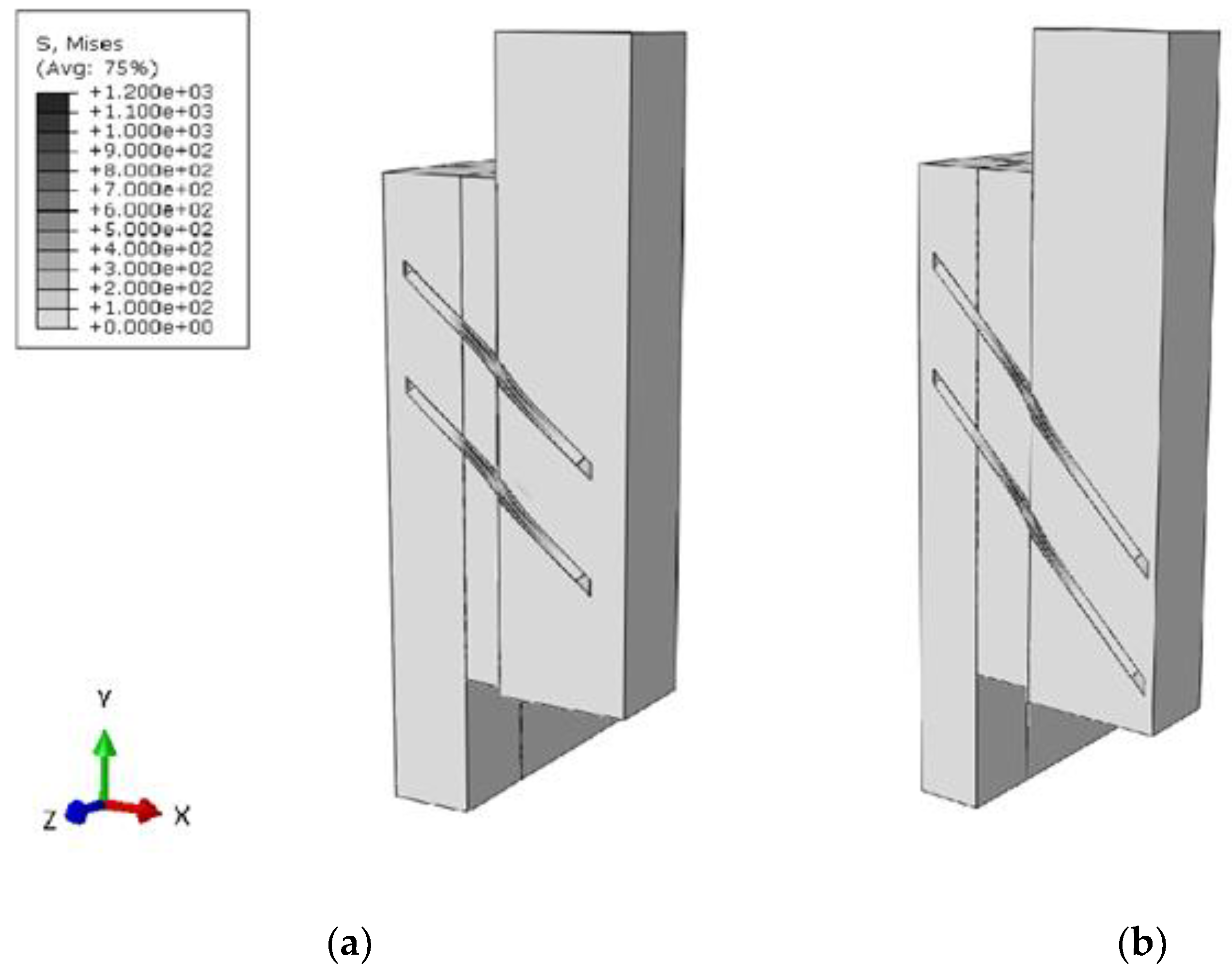
Table 1). The failure mode predicted by both the FE models resulted in the screw withdrawal (
Figure 6), which is also in line with the most recurrent failure mode of the experimental campaign. Given that the optimization of parameters was performed based on the pre-failure behaviour only, it can be noted that the post-failure force-displacement curves of FE numerical models slightly differ from the experimental measurements. However, it is also important to note that the present analyses were primarily focused on the until-failure behaviour of examined connections, and such an intrinsic limit of FE models was hence considered satisfactory for the purpose of current investigations.
5. Results of FE Numerical Parametric Study
Parametric studies were carried out using the FE models calibrated towards the experimental configurations, with the aim of identifying the parameters of the system that mostly influence its response in terms of stiffness
and
and strength
. To this aim, typical modifications were taken into account in terms of fastener arrangement and detailing as in
Figure 8.
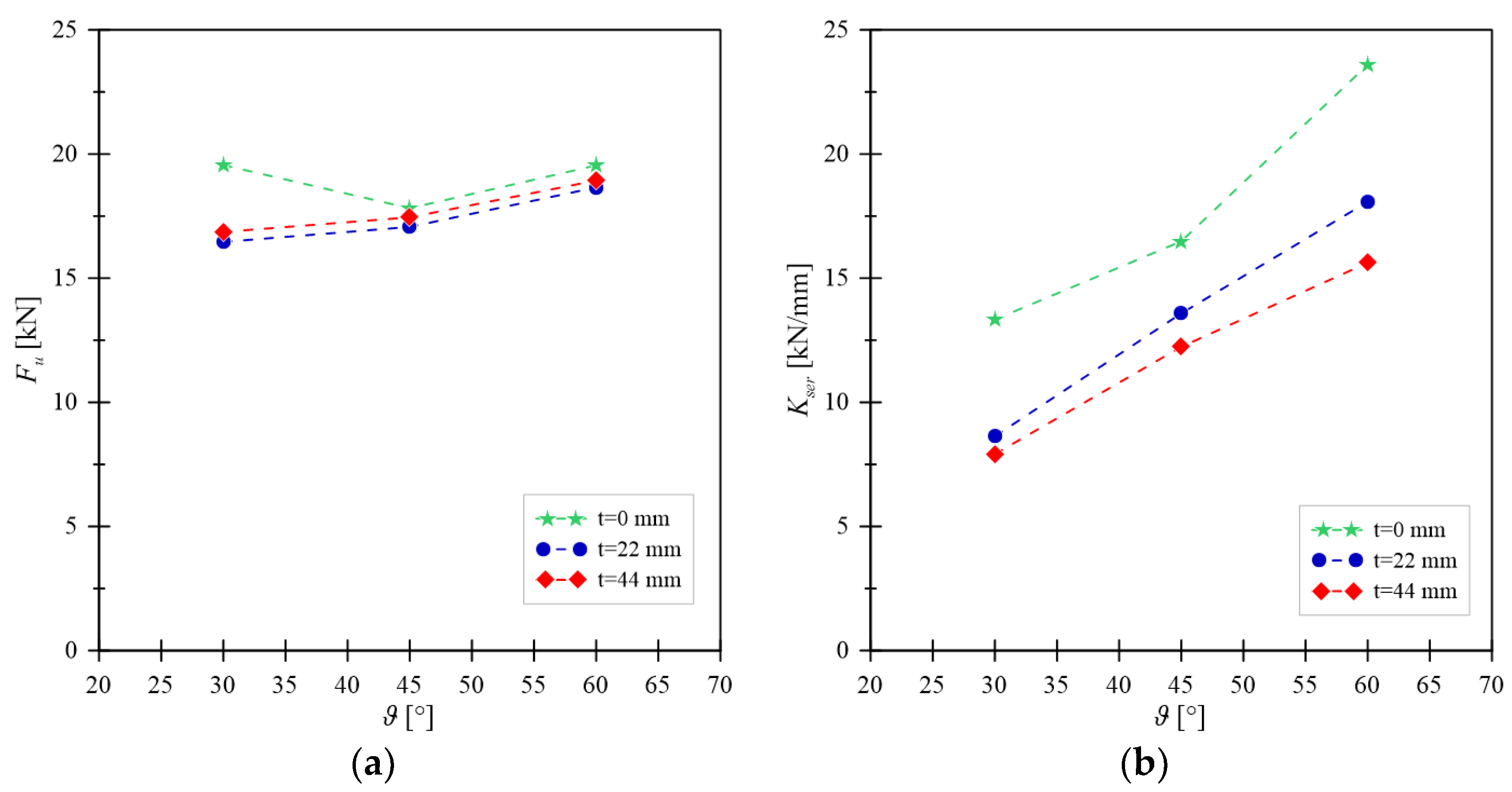
5.1. Screw Inclination and Interlayer Thickness
The first series of parametric studies aimed at investigating the dependence on the inclination of the screw and the thickness of the interlayer while maintaining the length of penetration of the screw into the main member
constant (
Figure 8). Eight models have been created assuming the experimental configuration E2 as reference model and by varying the thickness of the interlayer (0, 22 mm and 44 mm) and the angle of inclination of screw (30, 45 and 60°), see
Table 4.
A modest dependence of the resistance on the investigated parameters was generally observed (see
Figure 9a). In this regard, it is worth noting that the G1 configuration was the only one able to manifest a failure mode with the formation of a plastic hinge on the sliding surface.
In this configuration, due to the low inclination angle of screw and the absence of the interlayer, the sharing of forces transferred between the members through the flexural capacity of the screw is generally greater than in the other configurations. Overall, this effect leads to the overcoming of the flexural capacity before withdrawal capacity could be exceeded.
The results in terms of stiffness confirm the results of the analytical model developed by Di Nino et al. [
20], see
Figure 9b. As shown, by increasing the inclination angle of screw, a significant increase in stiffness can be obtained. The insertion of an interposed interlayer, even of limited thickness, produces a significant reduction in stiffness. By increasing the thickness of the interlayer, finally, the stiffness slightly decreases.
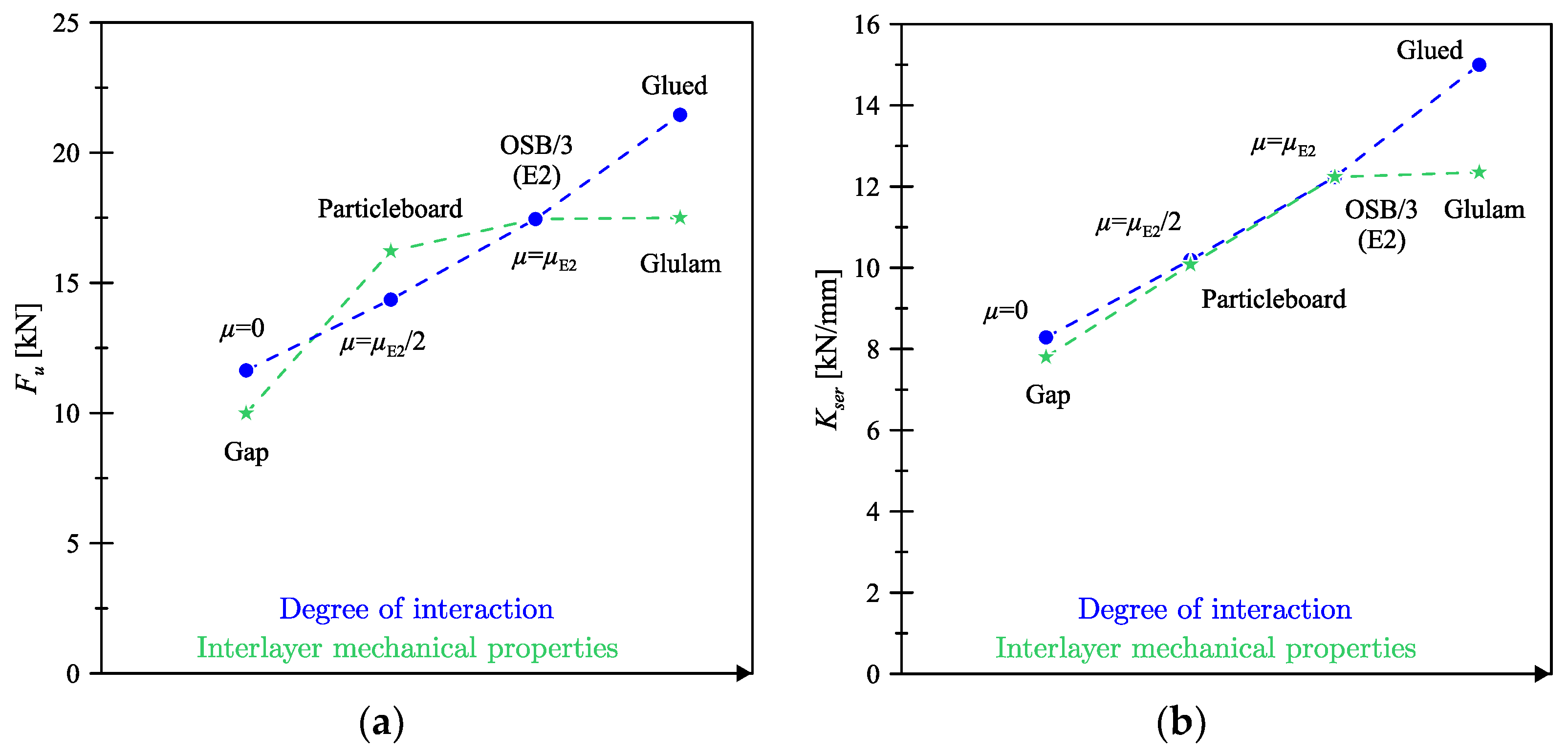
5.2. Interlayer-Timber Member Interaction and Interlayer Mechanical Properties
At a second stage, based on previous outcomes, different types of interaction between the OSB and the glulam member were numerically considered. The two limit cases of frictionless contact and glued contact were taken into account. In addition to the case with the previously recalled friction coefficient from the literature (i.e., model E2), the case with a halved coefficient was also considered, with the aim of evaluating the sensitivity of the overall load-bearing response of TCC system to this parameter. In this regard, the analysed FE model was found to be highly sensitive to the interaction between the members, both in terms of strength and stiffness.
Figure 10, in particular, shows the strength and stiffness modifications for varying the input mechanical properties of the interlayer. In addition to the reference
E2 configuration reported in
Figure 10 (i.e., with OSB/3 interlayer panel), more precisely, additional TCC configurations were defined as:
“particleboard”: interlayer made of particleboard (i.e., structural panels for use in wet areas, as defined in EN 12369-1:2001);
“glulam”: interlayer made of the same material as the main timber member;
and “gap”, that is with an interlayer consisting of a physical gap, but being still capable of keeping the timber and concrete members separated (with appropriate kinematic constraints) in the direction perpendicular to the sliding plane.
In this case as well, the investigated FE models were found to be sensitive to the mechanical properties of the interlayer, especially in terms of TCC connection stiffness. A significant reduction in strength and stiffness was observed for the FE model with “gap”, but such an outcome was mostly justified by the absence of friction phenomena (i.e.,
) between the concrete and the glulam members and the interlayer. It can in fact be noted in
Figure 10a,b that the “gap” and the “
” FE models approximately exhibit the same strength and stiffness capacities.
5.3. Friction Contribution and Test Setup
The friction sensitivity study further highlighted the important role of this parameter. For the configurations of
Table 4, in more detail, the graph in
Figure 11 shows the percentages of
which are transferred on the sliding plane through the screw and by friction. It can be noted that:
the share of force term which is transferred by friction is lower on the interlayer-glulam sliding plane (SL2) with respect to the concrete-interlayer sliding plane (SL1), due to the lower static friction coefficient;
for the configuration E1, which is similar to the G5 configuration in terms of inclination angle and interlayer thickness but is characterized by a different penetration length , the FE numerical analysis shows a negligible increase in the share of force transferred by friction on the sliding plane SL1. Conversely, on the sliding surface SL2, the share of force transferred by friction slightly decreases;
as the thickness of the interlayer increases, with constant inclination and length of penetration for the screw into the glulam member, the share of force transferred by friction clearly increases;
finally, as the angle of inclination of the screw increases with respect to the normal to the sliding plane, for constant thickness of interlayer and length of the screw penetration into the glulam member, the share of force transferred by friction decreases.
The friction force on the sliding plane is proportional, by means of the friction coefficient, to the force perpendicular to it. The force perpendicular to the sliding plane is given by two contributions: the component of the reaction forces to the internal stress of the screw, and the external force necessary to ensure the equilibrium of the entire connection assembly [
36].
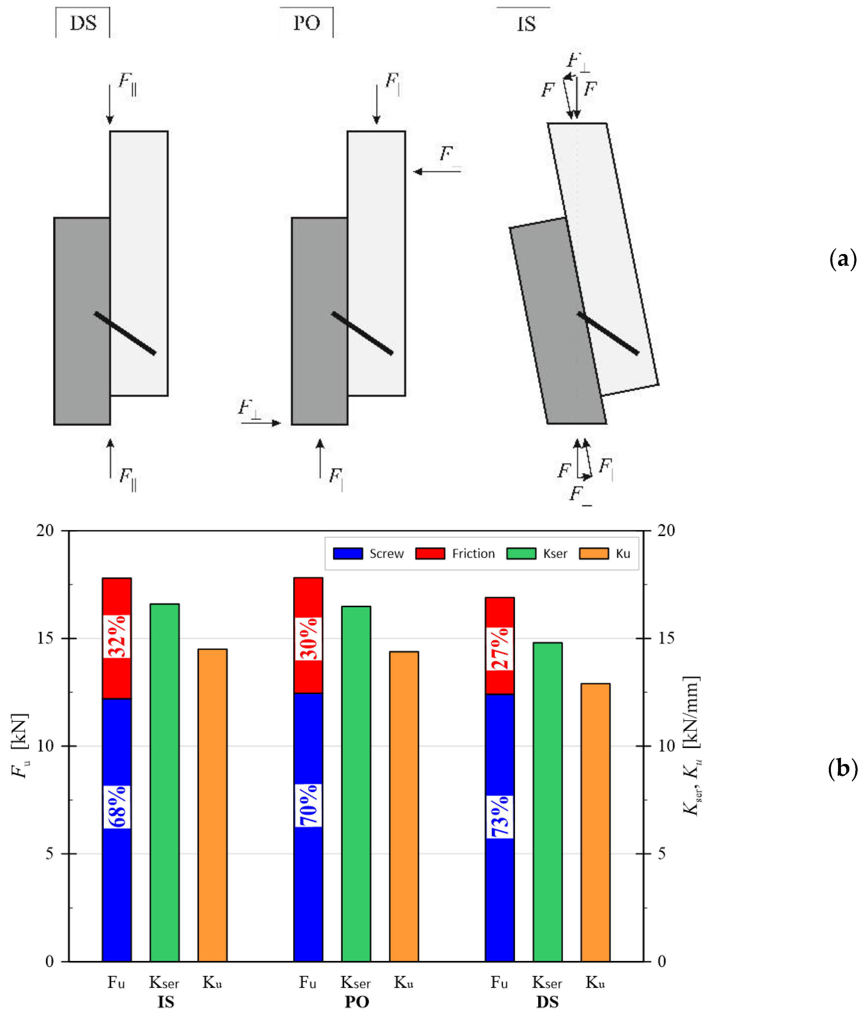
Figure 12a, in this regard, shows some of the most common experimental test configurations for the mechanical characterization of connection systems. A schematic layout is proposed for direct shear (DS), push-out (PO) and inclined shear (IS), respectively, with evidence of corresponding reaction forces and effects on sliding plane behaviour.
In the direct shear configuration (DS), more precisely, external forces are applied on the sliding plane, thus eliminating any external reaction forces perpendicular to the sliding plane itself. It is clear that such a condition has direct effects on the mechanical performance and load-bearing capacity of main members for TCC systems. In the case of push-out (PO) and inclined shear (IS) test setup conditions, there is evidence of a perpendicular component induced by the geometric configuration of the setup itself. In the case of a push-out test, in more detail, the perpendicular component depends on the lever arm of and , which is unknown. In the inclined shear case, is indeed represented by the component of the external applied force and is therefore a priori known.
To further explore the effect of these setup details on TCC performance, the FE model of the G4 system was used for a sensitivity analysis of synthetic results and TCC performance indicators. The graphical results in
Figure 12b, in this regard, show that through the different experimental setup conditions the force transferred between the members by the screw itself does not vary. The frictional force component undergoes an increase of 26% and 20% from the DS configuration to the PO and IS configurations, respectively, causing an overall ultimate force increase of 6% and 5%, respectively. The presence of the
force term, finally, leads to increases in stiffness between 11% and 13%, respectively. In the selected configuration, a greater force
was found especially in the case of inclined shear (IS), compared to push-out (with an average ratio equal to
).
5.4. Perfectly Glued Fastener
Finally, the attention of parametric numerical studies was focused on the ideal condition of a perfectly bonded screw. Preventing the screw withdrawal produces an increase of 40%, both in terms of strength and stiffness, and this can be achieved by considering the screw perfectly glued on the timber side. In this case, the failure mode passes from screw withdrawal, to screw and timber plasticization, which consequently leads to a more ductile behaviour of the TCC connection.
Such a limit case was numerically created and investigated starting from the E2 model by applying a rigid “tie” constraint to the interface between the screws and the timber components. In this way, the timber nodes and the screw nodes were rigidly and perfectly bound, thus simulating a typical case in which the glue-side failure mode is prevented.
For all the parametric studies herein discussed, a value between and was found in the presence of perfectly bonded fasteners. Sensitivity studies, in this regard, showed that the transition to a C45 concrete class could involve relatively small maximum variations in strength and stiffness, in the order of < 1%.
6. Discussion
The significant impact that the interlayer has on the load-bearing performance and mechanical parameters of timber-concrete composite connections is generally recognized by literature evidence. However, no distinction is commonly made between the different types of interlayers of typical use in constructions. In this study, the performed FE numerical simulations proved that connections with OSB and glulam interlayers have similar mechanical performance. However, in the case of highly deformable interlayers or particleboards, the strength and stiffness parameters for the examined connections can suffer from significant modifications, compared to previous cases.
Another important aspect is represented by the influence of friction, which is often neglected or minimally considered in a rough way, by simplified analytical models, for the stiffness and strength prediction. In some of the studied configurations herein presented, it was shown that friction can contribute by more than half to the strength of a given connection. Accordingly, further extended studies are needed to define empirical formulations capable of adequately taking into account such a contribution. From a practical point of view, benefits of friction phenomena could in fact lead to a considerable reduction in the number of fasteners which are commonly used in composite structures.
Finally, the role of the test setup for experimental investigations was properly emphasized by the present outcomes. Significant qualitative and quantitative differences were found between the direct shear (DS) test, the inclined shear (IS) test and the push-out (PO) test configurations. In this context, it is worth noting that all these differences are not minimally considered in current structural design regulations, and it is suggested to extend investigations and future elaborations.


 ,
, 
