Article

Experimental Study on Fire Resistance of Concrete Beams Made with Iron Tailings Sand

1
College of Civil and Architectural Engineering, North China University of Science and Technology, Tangshan 063210, China
2
Earthquake Engineering Research Center of Hebei Province, Tangshan 063210, China
*
Author to whom correspondence should be addressed.
Buildings 2022, 12(11), 1816; https://doi.org/10.3390/buildings12111816
Submission received: 26 September 2022 / Revised: 24 October 2022 / Accepted: 27 October 2022 / Published: 28 October 2022
(This article belongs to the Special Issue Fire Science and Safety of Bridge Structure)

Abstract

:
In order to measure the effect of iron tailings sand replacing natural sand on the fire resistance of concrete beams, five full-scale iron tailings sand concrete (ITSC) beams and two natural sand concrete (NSC) beams were conducted to fire testing under dead load and rising temperature conditions. The section temperature field, mid-span displacement, failure form, and fire resistance limit of ITSC beams under fire were analyzed. The main influence factors included different ISTC strengths (C30 and C40) and constraints. The analysis results were compared with those of NSC beams. The results show that the complete replacement of natural sand with iron tailings sand had little influence on the temperature field of concrete and reinforcement in simply supported beams and continuous beams under fire. The fire endurance of the ITSC simply supported beams was similar to that of NSC simply supported beams. When exposed to fire, the higher the strength of the ITSC, the better the fire resistance of the beam. The fire endurance of continuous beams was higher than that of simply supported beams. On the basis of the analysis of the fire resistance performance, it was found that iron tailings sand can replace natural sand to formulate concrete beams.

Graphical Abstract

1. Introduction

With the increasing frequency of building fires, the loss of people’s lives, property, and other direct or indirect economic losses caused by fires has sharply increased. The research on the fire resistance of building structures and components has attracted widespread attention [1,2,3,4,5,6,7,8]. Fire will cause buildings’ material properties and the structure’s overall performance to decline [2]. The reinforced concrete beam is an important horizontal load-bearing member of the structure and is also one of the most damaged members under fire. Its fire resistance significantly impacts the fire safety of the whole structure [3,4].
At present, many researchers have conducted a large amount of experimental and theoretical research on reinforced concrete beams under and after fire. For reinforced concrete members, the failure process at high temperature and the degradation of mechanical properties after high temperature are often closely related to the high-temperature bursting and spalling of concrete [5,6,7]. Dwaika [9] studied the fire resistance of six reinforced concrete beams with different concrete strengths, boundary conditions, temperature rise processes, and load ratios. The results show that the fire resistance of high-strength concrete beams was lower than that of ordinary concrete beams, and its cracking was more serious. The strength and load level of concrete have a significant impact on the fire resistance of reinforced concrete beams. Choi [10] studied the influence of concrete strength and cover thickness on the fire resistance of beams by conducting fire tests on four ordinary and high-strength concrete simply supported beams. The results show that the concrete strength had no influence on the distribution of the temperature field of the beam section. Before the concrete burst, there were essentially no vertical deflection changes of ordinary concrete beams and high-strength concrete beams. After the concrete burst, the vertical deflection of high-strength concrete beams increased significantly. Gao [11] established a 3D finite element analysis model in order to accurately predict the section temperature field and mechanical behavior of reinforced concrete beams under fire. The model focused on the bond slip between reinforcement and concrete that was previously ignored, being able to analyze the distribution and change of internal stress of reinforcement and concrete under fire more accurately. Ož Bolta [12] established a nonlinear finite element model to study the bending resistance of reinforced concrete beams in the process of temperature rise. Through experimental comparison, it was concluded that the model can better predict the load deformation curve of reinforced concrete beams under fire, as well as the temperature field distribution of the beam section and the bending failure form of the beam normal section.
Iron tailings sand (ITS) is the waste after iron ore beneficiation [13]. Iron tailings sand can be used to replace natural sand in the process of making concrete [14,15]. The application of iron tailing sand concrete (ITSC) in engineering not only solves the shortage of natural sand for concrete, but also realizes the reuse of iron tailings and solves the harm of tailings [16,17,18]. Up until now, many scholars have made many achievements in the research on the material properties of ITSC [18,19,20,21,22,23,24,25,26]. It has been shown that [17,18,19,20,21,22,23] the workability and durability requirements of concrete can be met by adjusting the mix ratio of ITSC, controlling the amount of admixture, and adding fly ash and mineral powder. Shettima [25] and Duan [26] studied the effect of ITSC content on the mechanical properties of concrete. The compressive strength and splitting strength of concrete increased at first and then decreased with the increase in the substitution rate of ITS. The elastic modulus and water absorption increased with the substitution rate of ITS. The drying shrinkage, fluidity, impermeability, and corrosion resistance decreased with the substitution rate of iron tailing sand. However, it was shown that [27,28] part of the components of ITSC will decompose in a high-temperature environment, and its mass loss was about 12% when the temperature reached 900 °C, resulting in its unstable properties in the high-temperature environment. There may be hidden dangers in the construction industry’s direct application of ITSC. Therefore, the research on fire resistance of ITSC beam has engineering application value for its design.
Although many researchers have conducted a large amount of research on the fire resistance of natural sand concrete (NSC) beams and the mechanical properties of ITSC at high temperature, the research on the fire resistance of reinforced concrete beams using ITS instead of NS has not been reported. Moreover, reinforced concrete beams are an important structural member bearing vertical load. It may be seriously damaged components under fire. It is necessary to study the fire resistance of reinforced concrete beams made with ITS. Compared with the ordinary NSC beam, fire tests were carried out according to the international standard ISO834 heating curve. The beams’ cross-section temperature field, mid-span displacement, fire resistance limit, and failure form were obtained under the fire. The effects of different ISTC strength (C30 and C40) and different constraint conditions on the fire resistance of the beam were analyzed systematically. It provided a basis for fire resistance optimization design, post-fire repair, and reinforcement of ITSC beams, as well as theoretical and technical support for the large-scale engineering application of iron tailings sand concrete.

2. Experiment Design

2.1. Specimen Design

In this experiment, the bending performance tests of five full-scale ITSC beams and two NSC beams with different concrete strengths and different constraints were carried out under fire. Three were simply supported beams and four were continuous beams. The simply supported beams and continuous beams lengths were 4100 mm and 7700 mm, respectively, and the section size was 200 mm × 400 mm. The dimensions and reinforcement of the beam are shown in Figure 1. The serial number of the continuous beam is represented by “CB”, the number of the simply supported beam is represented by “SSB”, the iron tailings sand concrete is represented by “ITSC”, and the natural sand concrete is represented by “NSC”. To compare the fire resistance of continuous beams under different fire conditions, CB-1 is subjected to double span fire, while CB-4 is subjected to single span fire. The design parameters of specimens are shown in Table 1. On the basis of the NSC mixing ratio, the ITSC mixing ratio was kept unchanged. The dosage of admixture and concrete sand ratio were adjusted to make the mixing material workability meet the requirements. The final concrete mixing ratio is shown in Table 2. In order to reduce the influence of moisture on fire resistance of beams, test beams were placed in a dry and ventilated place for 90 days after 28 days of curing. The measured compressive strength of C30 NSC was 32.26 MPa, and the measured compressive strengths of C30 and C40 ITSC was 31.98 MPa, and 39.86 MPa, respectively.

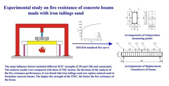
2.2. Loading Scheme and Heating System

The experiment was carried out in the fire laboratory of North China University of Science and Technology. All the test beams were subjected to the standard fire test under the condition of dead load-heating. In the test, the bottom surface and two sides of the beam were under fire. The beam ends were simply supported. The concentrated load was applied to the middle trisection in the beam span. The hydraulic jack equipped with a voltage regulator was used to load the test beam to the predetermined load and keep it constant. According to the European standard EC4 [29], the predetermined dead load applied by simply supported beams was 0.7 times ultimate load (considering the reduction factor of the load effect under fire), the same predetermined load was applied to continuous beams and simply supported beams with the same strength, as can be seen in Table 1. The load was measured by the pressure sensor. The furnace was heated according to the ISO834 standard heating curve. The fire resistance limit criterion was that the specimen deflection reached 1/20 of the calculated span [30]. After the specimens reached the fire resistance limit, they were unloaded and cooled naturally to room temperature. The test loading device is shown in Figure 2 and Figure 3.

2.3. Measuring Point Arrangement

The embedded thermocouples were used to measure the temperature field of the reinforcement and concrete at different location of the beam cross section. Two sections of the mid-span and the loading point were selected to arrange the thermocouple. The 11 concrete temperature measurement points were arranged along the horizontal and vertical directions for each section. In each section, the temperature of the longitudinal bars at the both top and bottom of the beam was measured. The stirrup was arranged with a temperature measurement point along the middle of the four sides. The measuring points are shown in Figure 4. The vertical displacement of the beam was measured by a wire displacement meter arranged at the top of the beam. The displacement measuring points were correspondingly arranged at the loading points support and in the mid-span of the beam. The specific measuring points were arranged as shown in Figure 5.

3. Experiment Result

3.1. Experimental Phenomenon

The test beam was loaded in stages at room temperature, and each stage was loaded with 20 kN for five minutes. After it was added to the predetermined load, the heating fire test was carried out according to the ISO834 heating curve until the test beam reached the fire resistance limit or 120 min. In the fire test process, the ITSC beam test was essentially the same as the NSC beam. After 10 min of ignition, water vapor appeared on the interface between the test beam and the furnace lid. The water vapor increased gradually with the increase in temperature. A water trace was formed on the top of the beam. With the progress of the fire test, the watermarks on the top of the beam gradually decreased and finally disappeared. To simulate the influence of the floor on the side of the beam subjected to fire, the furnace cover was used to clamp the top of the beam at the height of 100 mm to form a fire-free zone. When the furnace cover was opened after the test, it was observed that there was an apparent waterlogging line between the fire area and the non-fire area on the side of the beam. The non-fire area of the ITSC beam was dark grey, and the fire area was greyish yellow. The non-fire area of the NSC beam was grey, and the fire area was grey-white, as shown in Figure 6.
The simply supported beams reached the fire resistance limit in the firing process, and the test beams were hoisted after the cease-fire. The failure mode of the simply supported beams are shown in Figure 7, and the simply supported beams had cracks on the fire surface. The cracks were distributed in a network. The surface was bulging and loosening. There was a sizeable residual flexure deformation after cooling to room temperature.
The continuous beams did not reach the fire resistance limit after being exposed to fire for 120 min. After natural cooling of the continuous beams, static load tests were carried out until the continuous beams were destroyed. In the static load test, the step-load was applied at a rate of 20 kN controlled by displacement of 0.5 mm/min until the continuous beams were damaged. The failure forms of the continuous beam are shown in Figure 8. The continuous beams maintained good integrity under the fire for 120 min. There was only a slight burst occurred in the middle of the span. After cooling, there was a large recovery of bending deformation. In the static load test, there was few new main crack growing in the pure bending section. The width of the original main crack gradually increased until the failure.

3.2. Fracture Distribution and Failure Characteristics

Figure 9 shows the crack, burst, and damage of the simply supported beams after fire. The shadow represents the burst area. The number represents the maximun crack width of the beam after the fire in millimeters. The letters N and S represent the north and south sides of the beam, and E and W represent the east and west ends of the beam, respectively. It can be seen from Figure 9 that concrete bursting and spalling of different sizes occurred on the side of the simply supported beams. The spalling position was mainly located at the lower part of the mid-span pure bending section. In particular, large blocks of concrete in the upper part of the north support of the beam SSB-2 burst and fell, mainly due to the increase in concrete strength, the decrease in permeability and the greater steam pressure. The vertical cracks on the side of the simply supported beams were sparse and mainly distributed in the mid-span pure bending section. According to Table 3, after reaching the fire resistance limit, the maximum crack width of the pure bending section of beam SSB-1 and beam SSB-3 with low concrete strength were 13 mm and 14 mm, respectively. However, the maximum crack width of the pure bending section of beam SSB-2 with high concrete strength was decreased to 8 mm.
Figure 10 indicates that the crack development and failure pattern of the continuous beams under static load test failure form after the fire. As can be seen from the figure, with the increasing of load, the cracks under the fire of the pure bending section gradually developed upward, and the crack width increased gradually. Then, cracks appeared in the upper part of the middle bearing and gradually developed downward. Finally, the concrete in the compression area of the pure bending section was crushed, and the continuous beams were destroyed. The maximum crack widths of the continuous beams are shown in Table 4. It can be seen that the maximum crack widths of the single-span fire CB-4 beam and CB-2 beam with high concrete strength were small at 9mm and 8mm, respectively.

3.3. Temperature of Concrete and Reinforcement in the Beam

The measured furnace temperature curves of SSB-1, CB-1, and CB-4 beams were compared with the ISO834 standard heating curve shown in Figure 11. It can be seen that the fire heating curves of each test beams had the same heating trend as the standard heating curve, and the temperatures were similar.
Figure 12 shows the time history curves of concrete temperature at different heights of the mid-span section of the test beam under fire. According to the temperature distribution of the six groups of measuring points in the figure, it can be seen that the concrete temperature in both the ITSC beam and the NSC beam increased nonlinearly. The temperature field in the beam was non-uniformed because the ITSC was a thermal inert material. The concrete temperature in the beam decreased gradually along the beam height. The closer it is to the fire surface, the faster the temperature increased, with the temperature rise curve being convex. When the temperature reached 100 °C, part of the water in the beam evaporated and absorbed heat. Therefore, a temperature lag plateau would appear at about 100 °C.
Figure 13 shows the time history curves of the temperature of stirrups and longitudinal reinforcement in the test beams under fire. According to the temperature distribution of five groups of measuring points in the figure, the temperature distribution law of reinforcement in the ITSC beams was similar to that in the NSC beams. Affected by the heat absorption by water evaporation, the longitudinal and stirrup temperature curves near the top of the beam produced a temperature lag plateau at about 100 °C. The longitudinal reinforcement near the bottom of the beam and the stirrups close to the bottom and middle of the beam increased faster as they were closer to the fire surface.

3.4. Deformation after Being Subject to Fire

Figure 14 shows the vertical mid-span displacement of the test beam under fire as a function of time. It can be seen from the diagram that the deflection of the test beam under fire was the result of the combined action of load and temperature. The simply supported beam produced downward bending deformation under the action of high temperature. However, the bending deflection of the continuous beam was not apparent. As shown in Figure 14a, the mid-span displacement curve in the simply supported beam was divided into two segments, at rough 70 min. Before 70 min, the stiffness of the simply supported beam did not clearly deteriorate. The mid-span displacement in the span increased linearly with time. The increasing rate was slow. When the temperature exceeded 70 min, it can be seen from Figure 13 that the temperature of tensile longitudinal bars was close to 550 °C, the strength and stiffness of reinforcement are degraded. The increasing rate of the mid-span displacement increased significantly, showing a non-linear development trend. The continuous beam is a statically indeterminate structure with redundant constraints. The internal force redistribution would occur due to the decreased stiffness of the concrete in the firing process. The mid-span displacement of the continuous beam developed approximately linearly over the 120 min under fire and did not fail.

3.5. Fire Endurance and Residual Bearing Capacity

The failure criterion is that the mid-span displacement of the beam reached 1/20 of the calculated span and the beam was unable to continue to bear the vertical load under the fire circumstances [30]. The fire endurance of the simply supported beams are shown in Table 3. Because the fire endurance of the ITSC beam SSB-1 was 1.7% higher than that of the NSC beam, the ITS can replace NS completely. The fire endurance of the C40 beam SSB-2 is higher than that of the C30 beam SSB-1 by 14%. The higher the strength of ITSC, the higher the fire endurance.
The continuous beam did not reach the fire endurance after being exposed to fire for 120 min. The static load test was carried out until the continuous beams were destroyed after the continuous beams naturally cooled, The residual bearing capacity of the continuous beams are shown in Table 4. After being exposed to fire for 120 min, the influence factors such as ITC instead of NS, and single or full span fire on the residual bearing capacity was not taken into account. The residual bearing capacity of the C40 beam CB-2 is higher than that of the C30 beam CB-1 by 3.7%.

4. Discussion

Taking the ITS instead of the NS as the point of focus, and taking the concrete strength of ITS and the restraint conditions of beams as parameters, the performance of seven test beams after being exposed to fire were analyzed as follows:
(1) Using the iron tailings sand instead of the natural sand. As it is illustrated in Figure 7, Figure 8, Figure 9 and Figure 10, the test phenomena, the failure forms and the crack distribution were essentially very similar during the fire based on the comparison between NSC beams (SSB-3, CB-3) and ITSC beams (SSB-1, CB-1) with the same strength. The reason for the color change and beam cracking was the physical dehydration of cement mortar [31] and the interior change of concrete under fire [32]. The temperature rise under fire caused more cracks on the surface of the beam, and the cement mortar was seriously dehydrated [27,28]. It can be seen from Table 3 that the fire endurance (93 min) of SSB-1 beams was similar to that of SSB-3 beams (92 min). When reaching the fire endurance, the maximum crack width (13 mm) of SSB-1 beams was 7.67% lower than that of SSB-3 beams (14 mm). It can be implied from Table 4 that the residual bearing capacity (268 kN) of CB-1 beams after being exposed to fire for 120 min was similar to that of CB-2 beams (265 kN), and the maximum bending deformation and maximum crack width at failure increased by 7.14% and 6.67%, respectively, under failure. It can be seen from Figure 12 and Figure 13 that under the standard heating condition, the temperature field distribution and temperature change of concrete and reinforcement were likely to be the same, as reported by Choi and Gao [10,11]. Although iron tailings sand replace natural sand wholly, the concrete strength does not change. The fire resistance limit, temperature field of concrete and reinforcement, residual bearing capacity after fire, and crack width of beams under fire are similar [31]. Therefore, it is possible for the iron tailings sand to replace natural sand in terms of its benefits with regard to fire resistance limit, temperature field of concrete, and reinforcement of beams.
(2) Concrete strength of ITSC. The effect of ISTC strength on the fire resistance of RC beams can be illustrated by comparing the fire resistance limit [30]. It can be seen from Table 3 that the fire resistance limit (106 min) of the SSB-2 beam was 14% (13 min) higher than that of the SSB-1 fire resistance limit (93 min) when the concrete strength of ITSC increased from C30 to C40. According to reference [9], this can be mainly attributed to the faster degradation of strength properties of C30 ISTC. As can be seen from Table 4, after being exposed to fire for 120 min, the residual bearing capacity of the CB-2 beam was 3.7% higher than that of beam CB-1, and the maximum bending deflection at a failure was reduced by 13.3%. Therefore, similar to NSC, the higher the strength of ITSC, the better the fire resistance of the beam, on basis of the analysis of fire resistance limit and residual bearing capacity after fire [33].
(3) Restraint conditions. The mid-span displacements of CB-1 and CB-2 beams were only 43 mm and 38 mm after being exposed to fire for 120 min. These two beams meet the requirement of fire endurance. This can be attributed to the fact that the continuous beam has redundant constraints. The continuous beam is affected by redundant constraints under predetermined load and temperature in cases of fire with the internal force redistribution [34]. As shown in Figure 14 and Table 4, after exposure to fire for 120 min, the residual bearing capacity (268 kN) of full-span fire CB-1 beams was similar to that of single-span fire CB-4 beams (260 kN). The maximum bending deflection and maximum crack width increased by 9.1% and 77.8%, respectively. The effect of the redundant constraint and single-span exposed to fire enhanced fire resistance and contributed to sustaining burnout conditions [9]. Therefore, the fire endurance of the ITSC continuous beam was higher than that of the simply supported beam, and the fire resistance of the single-span continuous beam exposed to fire was superior to that of the double-span continuous beam under the same circumstances.

5. Conclusions

Standard fire tests were carried out on five full-scale ITSC beams and two NSC beams under the condition of dead load and rising temperature. The effects of ITS instead of NS, the concrete strength of ITS, and the restraint conditions on fire resistance were studied. The following conclusions were obtained:
(1) The complete replacement of NS with ITC had little influence on the temperature field of concrete and reinforcement in simply supported beams and continuous beams under fire. The temperature curves of concrete, longitudinal reinforcement, and stirrups near the top of the ITSC beams produced a temperature lag platform at about 100°C.
(2) The fire endurance of the ITSC simply supported beams was similar to that of the NSC simply supported beams. When exposed to fire, the higher the strength of the ITSC, the better the fire resistance of the beam. The fire endurance of the C40 ITSC simply supported beam was 14% (13 min) higher than that of the C30 ITSC simply supported beam.
(3) The C40 and C30 ITSC continuous beams was able to meet the requirement of 120min, and the residual bearing capacity of continuous beams was similar after 120 min of fire. The fire endurance of continuous beams was higher than that of simply supported beams. The fire resistance of single-span ITSC continuous beams exposed to fire was superior to that of double-span ITSC continuous beams under the same circumstances.
In conclusion, on the basis of the analysis of the fire resistance performance of ISTC beams and NSC beams in terms of temperature field of concrete and reinforcement, failure mode and fire resistance limit, iron tailings sand can replace natural sand to formulate concrete beams.

Author Contributions

Conceptualization, Y.Z. and Z.Y. (Zhinain Yang); methodology, Y.Z., Z.Y. (Zhinain Yang) and K.C.; software, B.G. and K.W.; validation, K.C. and Z.Y. (Zhinain Yang); writing—original draft preparation Y.Z., K.C. and Z.Y. (Zhinain Yang); writing—review and editing, Y.Z., Z.Y. (Zhinain Yang), Z.Y. (Zhiguo You), X.W. and K.C. All authors have read and agreed to the published version of the manuscript.

Funding

This research was supported by the Natural Science Foundation of Hebei Province, China (E2021209112, E2021209121), the Scientific Research Program of Hebei Higher Education Institutions, China (ZD2021085, JQN2021005), the Applied Basic Research Program of Tangshan Science and Technology Bureau (21130222c).

Institutional Review Board Statement

Not applicable.

Informed Consent Statement

Not applicable.

Data Availability Statement

The experiment data used to support the findings of this study are included in the article.

Conflicts of Interest

The authors declare no conflict of interest.

References

  1. Mathews, M.E.; Andrushia, A.D.; Kiran, T.; Yadav, B.S.K.; Kanagaraj, B.; Anand, N. Structural response of self-compacting concrete beams under elevated temperature. Mater. Today Proc. 2022, 49, 1246–1254. [Google Scholar] [CrossRef]
  2. Khaliq, W.; Khan, H.A. High temperature material properties of calcium aluminate cement concrete. Constr. Build. Mater. 2015, 94, 475–487. [Google Scholar] [CrossRef]
  3. Ryu, E.; Shin, Y.; Kim, H. Effect of Loading and Beam Sizes on the Structural Behaviors of Reinforced Concrete Beams Under and After Fire. Int. J. Concr. Struct. Mater. 2018, 12, 54. [Google Scholar] [CrossRef]
  4. Choi, E.G.; Shin, Y.-S.; Kim, H.S. Structural damage evaluation of reinforced concrete beams exposed to high temperatures. J. Fire Prot. Eng. 2013, 23, 135–151. [Google Scholar] [CrossRef]
  5. Phan, L.T. Pore pressure and explosive spalling in concrete. Mater. Struct. 2008, 41, 1623–1632. [Google Scholar] [CrossRef]
  6. Hassan, A.; Khairallah, F.; Elsayed, H.; Salman, A.; Mamdouh, H. Behaviour of concrete beams reinforced using basalt and steel bars under fire exposure. Eng. Struct. 2021, 238, 112251. [Google Scholar] [CrossRef]
  7. Le, Q.X.; Torero, J.; Dao, V.T. Stress–strain–temperature relationship for concrete. Fire Saf. J. 2020, 120, 103126. [Google Scholar] [CrossRef]
  8. Ma, W. Behavior of Aged Reinforced Concrete Columns under High Sustained Concentric and Eccentric Loads, Order No. 28542353 ed.; University of Nevada: Las Vegas, NV, USA, 2021. [Google Scholar]
  9. Dwaikat, M.B.; Kodur, V.K.R. Response of Restrained Concrete Beams under Design Fire Exposure. J. Struct. Eng. 2009, 135, 1408–1417. [Google Scholar] [CrossRef]
  10. Choi, E.; Shin, Y. The structural behavior and simplified thermal analysis of normal-strength and high-strength concrete beams under fire. Eng. Struct. 2011, 33, 1123–1132. [Google Scholar] [CrossRef]
  11. Gao, W.; Dai, J.-G.; Teng, J.; Chen, G. Finite element modeling of reinforced concrete beams exposed to fire. Eng. Struct. 2013, 52, 488–501. [Google Scholar] [CrossRef] [Green Version]
  12. Ožbolt, J.; Bošnjak, J.; Periškić, G.; Sharma, A. 3D numerical analysis of reinforced concrete beams exposed to elevated temperature. Eng. Struct. 2014, 58, 166–174. [Google Scholar] [CrossRef]
  13. Zuccheratte, A.C.V.; Freire, C.; Lameiras, F.S. Synthetic gravel for concrete obtained from sandy iron ore tailing and recycled polyethyltherephtalate. Constr. Build. Mater. 2017, 151, 859–865. [Google Scholar] [CrossRef]
  14. Prakash, A.; Swaminathen, A.; Ramu, A.; Chaitanya, B.K. Assessment of strength and durability parameters for concrete with partial replacement of coarse aggregates by iron slag and glass powder as an additive. IOP Conf. Series Mater. Sci. Eng. 2021, 1126, 012082. [Google Scholar] [CrossRef]
  15. Karthikeyan, B.; Kathyayini, R.; Kumar, V.A.; Uthra, V.; Kumaran, S.S. Effect of dumped iron ore tailing waste as fine aggregate with steel and basalt fibre in improving the performance of concrete. Mater. Today Proc. 2021, 46, 7624–7632. [Google Scholar] [CrossRef]
  16. Upadhyay, R.; Venkatesh, A.S. Current strategies and future challenges on exploration, beneficiation and value addition of iron ore resources with special emphasis on iron ores from Eastern India. Appl. Earth Sci. 2006, 115, 187–195. [Google Scholar] [CrossRef]
  17. Prabhu, G.G.; Hyun, J.H.; Kim, Y.Y. Effects of foundry sand as a fine aggregate in concrete production. Constr. Build. Mater. 2014, 70, 514–521. [Google Scholar] [CrossRef]
  18. Ismail, Z.Z.; Al-Hashmi, E.A. Reuse of waste iron as a partial replacement of sand in concrete. Waste Manag. 2008, 28, 2048–2053. [Google Scholar] [CrossRef]
  19. Ahmed, T.; Elchalakani, M.; Basarir, H.; Karrech, A.; Sadrossadat, E.; Yang, B. Development of ECO-UHPC utilizing gold mine tailings as quartz sand alternative. Clean. Eng. Technol. 2021, 4, 100176. [Google Scholar] [CrossRef]
  20. Shettima, A.U.; Hussin, M.W.; Ahmad, Y.; Mirza, J. Evaluation of iron ore tailings as replacement for fine aggregate in concrete. Constr. Build. Mater. 2016, 120, 72–79. [Google Scholar] [CrossRef]
  21. Oritola, S.F.; Saleh, A.L.; Sam, A.R.M. Characterization of Iron Ore Tailings as Fine Aggregate. ACI Mater. J. 2020, 117, 125–134. [Google Scholar] [CrossRef]
  22. Miraldo, S.; Lopes, S.; Pacheco-Torgal, F.; Lopes, A. Advantages and shortcomings of the utilization of recycled wastes as aggregates in structural concretes. Constr. Build. Mater. 2021, 298, 123729. [Google Scholar] [CrossRef]
  23. Kranti, J.U.; Sai, A.N.; Krishna, A.R.; Srinivasu, K. An experimental investigation on effect of durability on strength properties of M40 grade concrete with partial replacement of sand with copper slag. Mater. Today Proc. 2020, 43, 1626–1633. [Google Scholar] [CrossRef]
  24. Jayasimha, N.; Sujini, B.; Annapurna, B. A study on durability and strength properties of high strength concrete with partial replacement of iron ore tailings with fine aggregates. Mater. Today Proc. 2022, 62, 1922–1929. [Google Scholar] [CrossRef]
  25. Bezerra, C.G.; Rocha, C.A.A.; de Siqueira, I.S.; Filho, R.D.T. Feasibility of iron-rich ore tailing as supplementary cementitious material in cement pastes. Constr. Build. Mater. 2021, 303, 124496. [Google Scholar] [CrossRef]
  26. Duan, P.; Yan, C.; Zhou, W.; Ren, D. Fresh properties, compressive strength and microstructure of fly ash geopolymer paste blended with iron ore tailing under thermal cycle. Constr. Build. Mater. 2016, 118, 76–88. [Google Scholar] [CrossRef]
  27. Zhu, Q.; Yuan, Y.-X.; Chen, J.-H.; Fan, L.; Yang, H. Research on the high-temperature resistance of recycled aggregate concrete with iron tailing sand. Constr. Build. Mater. 2022, 327, 126889. [Google Scholar] [CrossRef]
  28. Hou, Y.F. Comparison of Effect of Iron Tailing Sand and Natural Sand on Concrete Properties. Key Eng. Mater. 2014, 599, 11–14. [Google Scholar] [CrossRef]
  29. British Standards Institution. Design of Composite Steel and Concrete Structures: Eurocode 4; British Standards Institution: London, UK, 2006. [Google Scholar]
  30. ISO 834-10; Fire-Resistance Tests-Elements of Building Construction-Part 10: Performance Criteria. ISO: Geneva, Switzerland, 1999.
  31. Huang, Z.; Padmaja, K.; Li, S.; Richard Liew, J.R. Mechanical properties and microstructure of ultra-lightweight cement composites with fly ash cenospheres after exposure to high temperatures. Constr. Build. Mater. 2018, 164, 760–774. [Google Scholar] [CrossRef]
  32. Zhang, B. Effects of moisture evaporation (weight loss) on fracture properties of high performance concrete subjected to high temperatures. Fire Saf. J. 2011, 46, 543–549. [Google Scholar] [CrossRef]
  33. Pan, Z.; Zheng, W.; Xiao, J.; Chen, Z.; Chen, Y.; Xu, J. Shear behavior of steel reinforced recycled aggregate concrete beams after exposure to elevated temperatures. J. Build. Eng. 2021, 48, 103953. [Google Scholar] [CrossRef]
  34. Yu, J.; Liu, Y.; Lu, Z.; Xiang, K. Experimental Study on damage and rehabilitation of reinforced concrete continuous member after fire. J. Tongji Univ. (Nat. Sci.) 2012, 40, 508–514. [Google Scholar] [CrossRef]
Figure 1. Arrangements of rebars for beams: (a) Simply supported beam; (b) Continuous beam.
Buildings 12 01816 g001aBuildings 12 01816 g001b
Figure 2. Test equipment: 1—longitudinal reaction steel beam; 2—hydraulic jack; 3—pressure sensor; 4—loading steel beam; 5—test beam; 6—steel bearing; 7—furnace wall; (a)—continuous beam loading device (b)—simply supported beam loading device.
Buildings 12 01816 g002
Figure 3. A full view of test equipment.
Buildings 12 01816 g003
Figure 4. Arrangements of temperature measuring points: (a) Schematic diagram of measuring points; (b) real map of measuring points.
Buildings 12 01816 g004
Figure 5. Arrangements of displacement transducers of beams: (a) Simply supported beam; (b) Continuous beam.
Buildings 12 01816 g005
Figure 6. Water stain drawing of beam side: (a) ITSC beam; (b) NSC beam.
Buildings 12 01816 g006
Figure 7. Failure modes of SSB under fire: (a) SSB-1; (b) SSB-2; (c) SSB-3.
Buildings 12 01816 g007aBuildings 12 01816 g007b
Figure 8. Failure modes of CB after fire: (a) CB-1; (b) CB-2; (c) CB-3; (d) CB-4.
Buildings 12 01816 g008
Figure 9. Crack, burst and damage of the simply supported beam under fire: (a) SSB-1; (b) SSB-2; (c) SSB-3.
Buildings 12 01816 g009aBuildings 12 01816 g009b
Figure 10. Crack development and failure pattern of the continuous beam under static load test failure after the fire: (a) CB-1; (b)CB-2; (c) CB-3; (d) CB-4.
Buildings 12 01816 g010aBuildings 12 01816 g010b
Figure 11. The time history curves of furnace temperature.
Buildings 12 01816 g011
Figure 12. Time history curves of concrete temperature inside specimens: (a) SSB-1; (b) SSB-2; (c) SSB-3; (d) CB-1; (e) CB-2; (f) CB-3; (g) CB-4.
Buildings 12 01816 g012
Figure 13. Time history curves of rebar temperature inside specimens: (a) SSB-1; (b) SSB-2; (c) SSB-3; (d) CB-1; (e) CB-2; (f) CB-3; (g) CB-4.
Buildings 12 01816 g013aBuildings 12 01816 g013b
Figure 14. Increase in mid-span displacement with time for specimens exposed to fire: (a) SSB; (b) CB.
Buildings 12 01816 g014
Table 1. Design parameters of beams.
Serial
Number
Concrete
Strength
Iron Tailings
Sand Content/%
Fired
Condition
Applied
Dead Load/kN
Fire Exposure Time/min
SSB-1ITSCC30100%-10893
SSB-2ITSCC40100%-110106
SSB-3NSCC300-10892
CB-1ITSCC30100%Double span108120
CB-2ITSCC40100%Double span110120
CB-3NSCC300Double span108120
CB-4ITSCC30100%Single span108120
Table 2. Mix proportion of concrete.
Concrete StrengthNatural Sand/
Kg/m3
Iron Tailings Sand/
Kg/m3
Cement/
Kg/m3
Fly Ash/
Kg/m3
Mineral Powder/
Kg/m3
Crushed Stone/
Kg/m3
Water/
Kg/m3
Water Reducing Agent/
Kg/m3
Water Binder Ratio
PC30840.502146075997170.57.000.51
ITCC30070127176951108215.99.350.51
ITC400572320901121026203.511.000.41
Table 3. Statistics of simply supported beam test results under fire.
Serial NumberIron Tailings Sand ContentCrack Width/mmFire Endurance/min
SSB-1100%1393
SSB-2100%8106
SSB-301492
Table 4. Statistics of continuous beam test results after fire.
Serial NumberIron Tailings Sand ContentMaximum
Deflection/mm
Maximum Crack Width/mmResidual Bearing Capacity/kN
CB-1100%6016268
CB-2100%528278
CB-305615265
CB-4100%559260
Publisher’s Note: MDPI stays neutral with regard to jurisdictional claims in published maps and institutional affiliations.

