Abstract
The formulas available in the literature for predicting the projectile impact response of reinforced concrete (RC) targets are generally developed based on the results of impact tests. Recently, however, in order to avoid performing involved and challenging projectile impact tests, the impact response of RC targets was predicted using the quasi-static punching response of RC slabs. In this paper, the concept is extended to concrete slabs strengthened with textile-reinforced mortar (TRM) or carbon fiber-reinforced polymer (CFRP) sheets externally bonded to the concrete surface. In 16 groups, 96 slabs of 600 × 600 × 90 mm size were cast and tested under quasi-static and impact loads. The slabs were reinforced with two types of reinforcement: ϕ8@100 mm and ϕ4@25 mm. The singly and doubly reinforced concrete slabs with rebar spacing of 100 mm were strengthened using externally bonded CFRP and TRM on the back side of the slab specimens. Two mixes of concrete, representing normal and high-strength concretes, were used. The results of the present study reveal that the CFRP and TRM strengthening of RC slabs enhanced the energy absorption in punching by 57–130% and 20–59%, respectively. The use of WWM in singly and doubly reinforced slabs also resulted in a 30–42% and 41–63% increase in energy absorption in punching, respectively. An earlier proposed model was modified to incorporate the influence of strengthening (CFRP and TRM) in the estimation of the projectile perforation energy of the strengthened RC slabs with the help of energy absorbed in their quasi-static punching. This perforation energy was then employed for predicting the ballistic limit of CFRP- and TRM-strengthened slabs. The predictions show good agreement with the experimentally observed ballistic limits.
Keywords:
CFRP; TRM; RC slabs; strengthening; impact load; correlation; perforation energy; quasi-static punching 1. Introduction
It is very important for structural designers of concrete buildings and bridges to be aware of the risks associated with the perforation of reinforced concrete slabs, strengthened or un-strengthened, during impact loading and punching of these slabs during quasi-static loading. The strengthening is required to overcome the deficiencies arising due to the aging/deterioration of structural elements [1] or increased demand. Substantial work has been done separately on the performance of slabs under impact and quasi-static punching. An investigation was conducted by Abdel-Kader and Fouda [2] on how steel ratios and reinforcement types affect the performance of reinforced concrete slabs under impact loads. In their study, they considered steel linings and embedded steel mesh on different slab surfaces. It was found that the size of craters on the back and front faces depended on the location of the rebar mesh. They also noticed that the steel lining significantly improved penetration resistance. Li et al. [3] investigated the effects of close-in blasts on RC slabs. The performance of hybrid steel wire mesh-micro steel fiber reinforcement was evaluated in a laboratory and in a field blast test. Further investigation of the field tests’ phenomenon was carried out by using a multi-material alternate-Lagrangian-Eulerian (ALE) algorithm. Almusallam et al. [4] investigated the efficacy of steel fibers combined with plastic fibers (i.e., hybrid fibers) in increasing the impact strength of RC slabs. Under the impact of steel projectiles with Bi-conic nose shapes, 54 square slab specimens having a constant thickness of 90 mm were tested. For half of the specimens, normal strength concrete was used, and for the other half, high strength concrete was used. In both directions, the opposite side of the striking face was reinforced with ϕ8 bars at a center-to-center distance of 100 mm. They found that the hybrid fibers reduced crater size, penetration depth, crack count, and concrete ejection mass. In addition, they also proposed analytical equations for assessing the penetration depth, ballistic limit, and, from the front and back of the slab, concrete ejected masses. The results of the test were in line with the predictions. The impact performance of concrete slabs was studied by Zineddin and Krauthammer [5] to improve the protective design of concrete structures. By testing 3353 × 1524 × 90 mm slabs, they examined how slab reinforcements affect the dynamic response. There were three reinforcement options: two-wire meshes of wire diameter 5 mm placed under 25 mm of concrete covers; one steel bar mesh #3 (wire diameter: 1.2 mm, and aperture: 7.3 mm) placed in the halfway point (i.e., middle) of the specimen’s thickness; and both sides of the slab have steel bar mesh #3 placed beneath 25 mm of concrete covers. The impact experiments were carried out using a sophisticated impact hammer device dropped from 152-, 305-, and 610-mm heights on RC slabs. The results of this experiment indicated that steel reinforcement quantity and drop height affect slab behavior. The behavior of prestressed concrete plates subjected to falling mass impact was investigated by Iqbal et al. [6]. A constant mass of 243 kg was allowed to fall freely from 500 and 1000 mm height at the center of target plates under the action of gravity. The square-shaped targets (800 mm × 800 mm) were pre-tensioned to 10 and 20% of their characteristic compressive strength (60 MPa). Impact forces, reactions, displacement, and energy absorption capacity were measured, studied, and compared with those of identical non-prestressed concrete plates. Both prestressed and non-prestressed concrete targets were examined for damage mechanisms and post-impact damage. The load-displacement curve was used to determine the energy absorbed by the given target plate. On ABAQUS/Explicit code, the drop impact response of prestressed and non-prestressed concrete plates was numerically simulated. To calculate the energy absorption capacity and peak displacement of plates, an analytical model based on mass, momentum, and energy conservation was also developed.
Xing et al. [7] fired 24 shots on thin slabs of sandstone with three nose-shape projectiles (i.e., flat, hemispherical, and conical) at velocities ranging from 120 to 403 m/s by a one-stage gas gun. Perforation limit, ballistic limit, and residual velocity equations were proposed for intermediate-velocity perforation models. They observed that, in the intermediate-velocity perforation model, the minimum velocity required to perforate a thin slab is 71% less than in high-velocity perforation. Wang et al. [8] investigated numerically the ballistic performance of PC slabs subjected to hard missile impact through finite element (FE) modeling. The method for introducing prestressing force is specifically investigated, and the feasibility of the established models is validated against existing experimental results. Using the models, a comparative study is conducted between PC and reinforced concrete (RC) slabs, where prestress and prestressing bars are decoupled. According to the study, prestress is the primary cause of the enhanced ballistic resistance of PC slabs, while prestressing bars are the secondary cause. A major reason for the increase in ballistic resistance is the confinement effect applied to the concrete. An empirical formula for the critical perforation velocity of PC slabs is developed using mechanical and regression analysis. Furthermore, the proposed formula allows for a straightforward parametric study, which could simplify estimations in the ballistic design of PC slabs.
A performance-based design (PBD) framework was developed by Gangolu et al. [9] for nuclear containment structures (NCSs) subject to missile impact. Multi-level PBD was considered rather than single-level conventional collapse-based design. Based on available numerical data, Bayesian inference was used to evaluate the unknown model parameters. Finite element (FE) numerical modeling (LS-DYNA) provided the data of reinforced concrete (RC) and prestressed concrete (PC) panels subjected to a missile impact. In addition, formulae for determining penetration depth, perforation limit, and residual velocity were developed. Using these probabilistic models, the NCS can be designed to withstand ballistic missile attacks.
Zhang et al. [10] studied the penetration depth of RC structures, in particular those used in nuclear power plants (NPPs) as containment walls. They conducted a series of 1/10 reduce-scaled engine impact tests on 150 mm thick RC panels using an advanced large-caliber air gas gun. 94 m/s to 184 m/s were the striking velocities. A record of the impact process, the missile’s deformation, and the panel’s damage were taken. An existing rigid projectile formula was modified by introducing a reduction coefficient of 0.5 based on the present and existing test data, thus predicting the penetration depth of RC panels struck by the deformable engine more accurately and practically than NEI (Nuclear Energy Institute) recommendations.
To better predict possible perforation of reinforced concrete slabs subjected to impacts, Baroth et al. [11] developed both analytical and finite element models. Using a revised constitutive model for concrete, finite element simulations were conducted with Abaqus explicit code. Both hard and soft impacts were analyzed in detail for ballistic limits and residual velocities. The predictions were based on a recent formulation of concrete compressive strength based on deviatoric stresses. Results from numerical and analytical analyses were in agreement with those obtained from experimental tests of bending and punching.
Substantial work also exists on the response of strengthened and un-strengthened slabs under quasi-static punching loads. In RC slabs, FRP sheets were used on the tension surfaces by Erki and Heffernan [12]. This resulted in the improvement of flexural stiffness, punching shear capacity, and delay in flexural cracking. The punching response of RC flat slabs, strengthened with carbon fiber-reinforced polymer (CFRP) sheets, was investigated by Wang and Tan [13]. Punching loads increased by an average of 8% over the controls for specimens reinforced with FRP sheets. Binici and Bayrak [14] reinforced RC flat plates with CFRP strips to improve punching shear resistance during punching. It has been shown that, by strengthening, the failure surface can be moved away from the column, and the load-bearing capacity increased by 51%. The effect of externally bonded CFRP strips on punching shear in interior slab-column connections was studied by Soudki et al. [15]. A significant improvement in structural performance was observed when slab-column connections were strengthened with CFRP. A 29% increase in punching capacity and an 80% increase in stiffness were observed in strengthened slabs. GFRP laminates were used by Chen and Li [16] to improve the shear strength of slabs. The researchers found a significant increase in punching strength by externally bonding GFRP laminates to slabs. A low steel reinforcement ratio, however, resulted in better performance for GFRP laminates. For strengthened slabs, analytical equations were proposed to calculate punching strength. By using inorganic binders, namely cement-based mortars in fiber composites, the use of TRM (textile-reinforced mortar) for concrete applications is proving to be a viable alternative to fiber-reinforced plastic. In TRM, textiles consist of woven, knitted, or even unwoven fiber rovings that are arranged in two directions (usually orthogonally). In the past, some interesting studies were conducted on the quasi-static response of RC members strengthened with TRM [17,18].
The aforementioned review shows that the formulas available in the literature for predicting the impact response of RC targets under projectile impact are based on the results of projectile impact tests. Recently, however, a mathematical model was proposed by the authors [19] for correlating the quasi-static punching response of RC slabs to their impact response. This helps in replacing more arduous impact experiments with relatively much more convenient quasi-static punching tests. In this paper, the concept is extended to concrete slabs strengthened with TRM or CFRP sheets externally bonded to the concrete surface. In this study, 96 slab specimens were prepared and tested in 16 groups. With the aid of energy absorbed in their quasi-static punching, an earlier proposed model [19] was modified to incorporate CFRP and TRM strengthening for estimating the perforation energy of strengthened RC slabs. This perforation energy was then employed for predicting the ballistic limit of CFRP- and TRM-strengthened slabs.
2. Experimental Program
2.1. Test Specimens
RC slabs have a dimension of 600 × 600 × 90 mm. Two types of reinforcement were used in the slabs, viz., one layer of 8 mm bars at a center-to-center distance of 100 mm on the rear face (steel percentage = 0.71%) and two layers of 4 mm bars at a center-to-center spacing of 50 mm on both faces (steel percentage = 0.69%). Thus the total percentage of steel in concrete slabs was kept nearly the same for the two reinforcement schemes. Singly reinforced concrete slabs were reinforced with rebars on the rear face (opposite to the projectile strike face). These slabs are reinforced, as shown in Figure 1. The strength of singly and doubly reinforced concrete slabs with a 100 mm rebar spacing was enhanced by externally bonding CFRP and TRM on the rear face of the slabs (Figure 2). Single-layer CFRP sheets with fiber alignment along the span were used for the CFRP strengthening. However, for TRM strengthening, a single layer of bidirectional carbon textile was employed. The total number of slab specimens was 96, six for each type. Table 1 summarizes the experimental program.
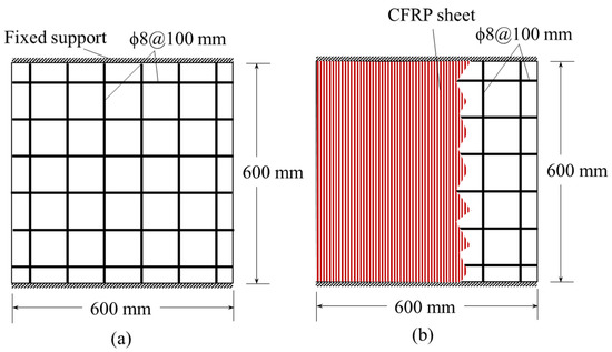
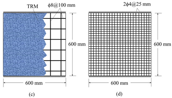
Figure 1.
Reinforcement and strengthening details of test specimens. (a) Control slab (b) CFRP-strengthened specimen (c) TRM-strengthened slab (d) Welded wire mesh (WWM) (Note: In singly reinforced slabs, the rebar details shown in the figures are applicable for back face, whereas, for doubly reinforced slabs, these details are applicable for both faces; CFRP and TRM strengthening is provided on the back face only).
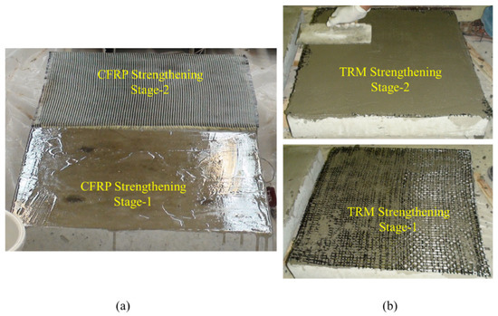
Figure 2.
RC slabs strengthened with externally bonded: (a) CFRP sheet; and (b) TRM.

Table 1.
Experimental program.
One slab from each group was tested using a quasi-static load applied by the projectile (used for impact testing). The remaining five slabs were tested under projectile impact. Steel projectiles with a diameter of 40 mm and a weight of 0.8 kg were used in the study. The length of its aft body was 80 mm, and thus its total length was 100 mm, which was more than the thickness (90 mm) of the RC slabs.
There were two batches of slab specimens for the two concrete mixes, M1 and M2. Wooden molds were used to cast the specimens. The fabricated steel cages were placed in the mold with cover blocks. Ready-mixed concrete with a maximum aggregate size of 9 mm and a slump of 18 mm was used to cast the slabs. Using a vibratory pin, the concrete mix was compacted into a single layer. The slab specimens were screeded immediately after casting and then cured for two weeks by covering them with moist burlap and polythene. Two weeks later, specimens were removed from the forms and allowed to dry for two more weeks. During each casting, six standard concrete cylinders were also prepared.
2.2. Materials and Their Properties
Two mixes of concrete, M1, and M2, were used in the preparation of specimens. The compressive strengths of mix M1 and M2 were 40 and 63 MPa, respectively. The two mixes represent normal, and high-strength concretes, respectively [20]. A local ready-mix plant supplied the concrete of the desired strength. Concrete was prepared with Portland cement type I. There was a mixture of fine and coarse aggregates in the aggregates. Fine aggregates were a mixture of silica and white sands; crushed limestone with a maximum size of 9 mm was used as coarse aggregates.
ASTM A370 [21] was used to test the 8 mm and 4 mm rebars. Three specimens of rebar were tested with a universal tensile testing machine equipped with hydraulic grips. The average yield and tensile strengths of three specimens of 8 mm rebars were 510 and 538 MPa, respectively. These values for 4 mm rebars were 317 and 349 MPa, respectively.
3. Quasi-Static Punching Test of RC Slabs
The first phase of the present study involved testing slabs against a quasi-static punching load. A steel cylindrical penetrator with a spherical nose of 40 mm diameter applied the punching force. Later, the same penetrator was used as an impact projectile. A punching load was applied to the slabs after clamping the two opposite edges (as in the projectile impact tests). At the center, the load was applied so that no rebar in M1-100 and M2-100 slabs came along the force. Thus, the location of the applied load for these slabs had minimum punching resistance. However, for M1-25 and M2-25 slabs, due to closer spacing, the penetrator/projectile was intercepted by the rebars. By using LVDTs, the slabs were monitored for their state of deformation over time. A quasi-static load of 18 kN/min was applied to the specimens through a spherical-nosed projectile until failure was achieved [22]. A data logger was used to measure displacement and incremental load (Figure 3). The penetrator was pushed upward using a hydraulic jack to punch the slab (Figure 3).
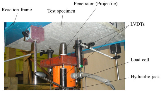
Figure 3.
Test setup for quasi-static punching test of RC slabs using projectile as a penetrator.
3.1. Failure Modes and Load-Displacement Variation in Quasi-Static Punching
Some of the RC slabs fail in punching shear modes are shown in Figure 4. These figures show the damage caused to the slabs’ upper face (the rear face). The strengthened slabs show pushing of CFRP or TRM layer(s), thereby keeping the damage localized as compared to the unstrengthened slabs of 100 mm rebar spacing. The load-displacement plots for the RC slabs are shown in Figure 5 and Figure 6. It is interesting to observe that every load-displacement curve has two peaks. Although the second peak can be clearly seen in strengthened and WWM-reinforced slabs, it is not very sharp in the control specimen. As a result of the resistance provided by the rebars on the back face as well as the strengthening layer (if present), a second peak load is generated when the concrete cone is punched. Because the rebars in control slab specimens are spaced more widely than those in WWM reinforced slabs, the effect of back face reinforcement is less pronounced in control slabs, resulting in a lack of a definite second peak. Observing the curves of control slabs carefully, however, there appears to be a second peak in the load-displacement curves.
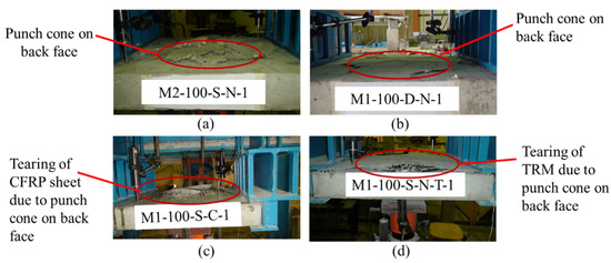
Figure 4.
Quasi-static punching failure of: (a) M2-100-S-N-1; (b) M1-100-D-N-1; (c) M1-100-S-C-1; and (d) M1-100-S-N-T-1.
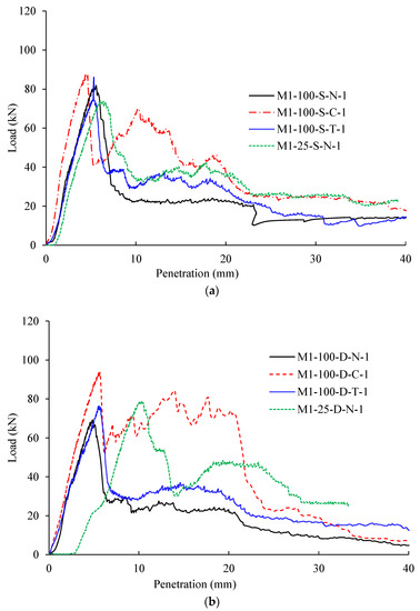
Figure 5.
Load vs. projectile penetration plots for concrete slabs of mix M1: (a) singly reinforced; (b) doubly reinforced.
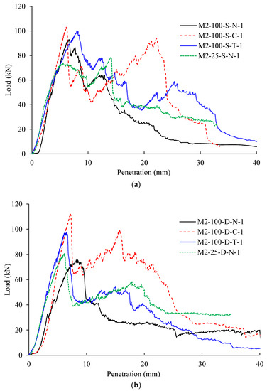
Figure 6.
Load vs. projectile penetration plots for concrete slabs of mix M2: (a) singly reinforced; (b) doubly reinforced.
3.2. Energy Absorption during Quasi-Static Punching
The energy absorbed by slabs during quasi-static punching is shown in Figure 7. The observations made from the plots for the singly and doubly reinforced slabs are:
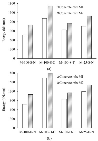
Figure 7.
Results of quantitative analysis of the energy absorbed during quasi-static punching of concrete slabs: (a) singly reinforced and (b) doubly reinforced.
Singly Reinforced Slabs:
- 1
- Energy absorption increases significantly for CFRP-strengthened slabs, ranging from 57% to 70% for the two mixes.
- 2
- Although peak loads of TRM-strengthened slabs are not significantly affected, energy absorption increases between 20% and 59% for the two mixes.
- 3
- The percent increase in energy absorption during the punching of WWM slabs varies from 30% to 42% for the two mixes.
Doubly Reinforced Slabs:
- 1
- The CFRP-strengthened slabs demonstrate a significant increase in peak loads in terms of energy absorption during punching, ranging from 87% to 130%.
- 2
- There is a nominal increase in energy absorption when the TRM-reinforced slabs are punched, with a value ranging from 28% to 33%.
- 3
- The punching of WWM slabs increases energy absorption by 41% to 63% for both mixes.
Results of quasi-static tests of load-displacement and energy absorption indicate that CFRP-strengthened RC slabs have superior punching resistance than TRM-strengthened RC slabs. The WWM involving the use of smaller diameter rebars at close spacing is found to have increased the punching resistance moderately.
4. Impact Testing of Slabs
Testing of RC slabs clamped on two opposite edges against projectile impact was performed at King Saud University’s impact testing facility. With the impact penetration tester (Figure 8), the projectiles were fired at the desired velocities. The wider-spaced rebar slabs (M1-100 and M2-100) were positioned so as to avoid the strike of the projectile on the rebars. However, in M1-25 and M2-25 slabs, the projectiles were intercepted by the rebars due to the closer spacing of the rebars in these slabs. The projectile employed for impact tests was the same as the penetrator used in the quasi-static tests.
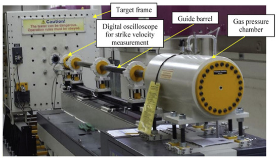
Figure 8.
The gas gun used for projectile impact tests.
Observed damage consisted of the following six types: (i) spalling with concrete fragments flying, (ii) crushed aggregates in the impact zone, (iii) rear face scabbing with dislodged concrete fragments, (iv) slab cracking, (v) CFRP sheet or TRM fracture and (vi) rupture of rebars. The fracture of rebars was observed only in WWM-reinforced slabs due to the close spacing of wires for this type of reinforcement. When the projectile struck the concrete surface, concentrated forces created a crater on the front face. The craters on the rear face were generally larger than those on the front face. The damage observed in concrete slabs at the projectile strike of about 125 m/s is shown in Figure 9. Only back face damage is shown in the figure. The size and shape of the craters on the rear face varied depending on the impact velocity, concrete strength, and presence of the CFRP sheet or TRM. It appears that the rear face was scabbed primarily by elastic compression waves that propagated during the impact and were reflected by the rear surface as tensile waves [23,24]. Whenever the resultant tensile stress exceeds the dynamic tensile strength, a crack occurs in the concrete matrix. CFRP sheet and TRM modified the incident compression wave as well as the reflected wave, causing greater damage to the rear face.
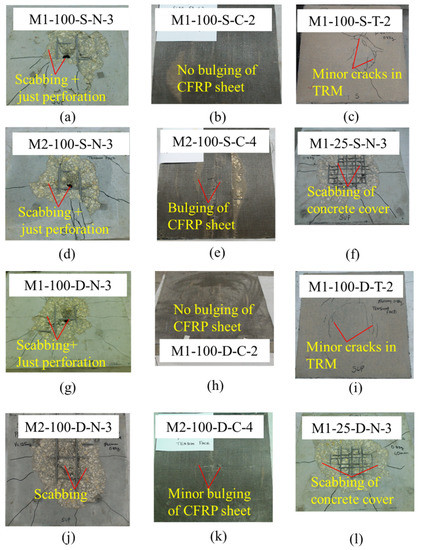
Figure 9.
Back face damage caused by projectile strike at ~125 m/s in slabs: (a) M1-100-S-N-3; (b) M1-100-S-C-2; (c) M1-100-S-T-2; (d) M2-100-S-N-3; (e) M2-100-S-C-4; (f) M1-25-S-N-3; (g) M1-100-D-N-3; (h) M1-100-D-C-2; (i) M1-100-D-T-2; (j) M2-100-D-N-3; (k) M2-100-D-C-4; (l) M1-25-D-N-3.
The back face scabbing and hence the generation of debris cloud and secondary projectiles got considerably reduced for CFRP-strengthened, TRM-strengthened, and WWM-reinforced slabs. As compared with CFRP strengthening of RC slabs, TRM strengthening performed equally or even better. In addition, the ballistic limit increased significantly when WWM was used as a substitute for rebars.
In Figure 10, damage levels are shown for projectile impact tests on slabs as a function of , where V is strike velocity and VBL represents ballistic limit. A mean of the velocity that causes perforation and the maximum velocity that does not cause perforation was taken as the experimental ballistic limit. The data points for DL6 indicate a perforating slab, so they lie above the horizontal line, corresponding to = 1; however, the data points for DL1 through DL4 indicate the projectile’s kinetic energy was less than that required for perforating slabs, so they lie below the horizontal line. On the horizontal line, DL5 indicates a perforation with zero residual velocity, corresponding to = 1. The damage level DL3 and DL2 data points are below DL4 since the kinetic energy of the projectile to perforation energy of the slab are less than DL4.
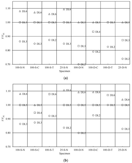
Figure 10.
Comparison of damage levels between different test specimens based on (DL1: Front face indentation without cracks; DL2: Rear face cracks without scabbing. No cracks are visible on the front face; DL3: A cavity formed on the front face with radial cracks; The back face has significant cracks; DL4: A cavity on the front face with scabbing on the back; DL5: There is almost no residual velocity after perforation; DL6: Perforation with residual velocity) for slabs of the concrete mix: (a) M1; and (b) M2.
5. Prediction of Ballistic Limit
As the same projectile was used in quasi-static testing of concrete slabs in punching, the energy absorbed was employed for assessing the ballistic limit. The perforation energy of slabs under projectile impact is greater than the energy absorbed in quasi-static penetration of slabs resulting from strain rate effects during impact loading. The perforation resistance of the slab for a projectile of mass M is expressed in terms of the perforation resistance parameter z:
where p = perimeter of the cross-section of the projectile in m; cr = spacing of reinforcing bars in m; rs = steel rebar percentage; rc = percentage of CFRP fibers; rt = percentage of TRM; M = projectile mass in kg; H0 = RC slab thickness in m; ρc = density of concrete in kg/m3; and = concrete compressive strength in MPa. The parameter, z, is an updated version of the parameter used in the authors’ previous study [19], which was similar to the term used in the ballistic limit prediction formula of UKAEA [4,25] after incorporating the effect of CFRP and TRM strengthening through the use of rc and rt terms:
where and are the thickness of CFRP and TRM, respectively. In longitudinal and transverse directions, respectively, and represent the ultimate strength capacity of CFRP and TRM strips. In CFRP/TRM strips, the stress is calculated from strain compatibility and possible delamination failures as [22]:
In the above equation, represents the strain determined from the compatibility of strain (); represents the strain of steel at yield; and represents the debonding strain of CFRP/TRM estimated by [26]:
CFRP/TRM strips’ ultimate strain and strength are represented by and ; CFRP/TRM strips’ modulus of elasticity and thickness are represented by and and n represents the number of CFRP/TRM strips; and represents the steel ratio.
In Figure 11, the ratio of projectile kinetic energy to quasi-static punching energy is plotted against parameter z. Perforation data and non-perforation data are separated in this figure by a line. All the test data follow the desired trend except for a few data points. Thus, this line represents the perforation limit and can be mathematically represented by the following expression:
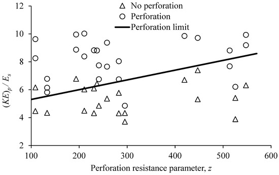
Figure 11.
Variation of (KE)p/Es with perforation resistance parameter, z. ((KE)p = projectile kinetic energy at strike, Es = energy absorbed in quasi-static punching).
In the above expression, represents the energy required for perforation, represents the energy absorbed by the slab during quasi-static punching and α, β represent the model parameters, which are obtained as 0.007 and 4.6, respectively. These parameters are the same as those obtained in the authors’ previous study [19]. It is noteworthy that Equation (6) is basically the same as the dynamic increase factor commonly used in dynamic analysis. In the present study, a concept was given through Equation (6) for correlating quasi-static response (which is easier to perform) to impact behavior. However, in the present study, the value of used in Equation (6) was taken from the experiment. In the future, when sufficient data are available, an equation can be developed for the estimation of . Equation (6) was employed to calculate , which was then used for the estimation of the ballistic limit , as follows:
The ballistic limit calculated from the above-proposed equation is plotted against projectile strike velocity in Figure 12. To match the experimental values, the points indicating the perforation in RC slabs should lie beneath the line of equality. The no-perforation points, however, should lie above the equality line. With the exception of a few data points that lie within a ±15% error band, the equality line clearly separates non-perforation data from perforation data. The proposed equation clearly illustrates a strong correlation between dynamic and quasi-static perforation energies for unstrengthened and strengthened slabs cast with different rebar spacing varying from very small spacing, essentially requiring rupture of rebars for perforation, to the large spacing necessitating the only perforation of concrete without any interaction with rebars.
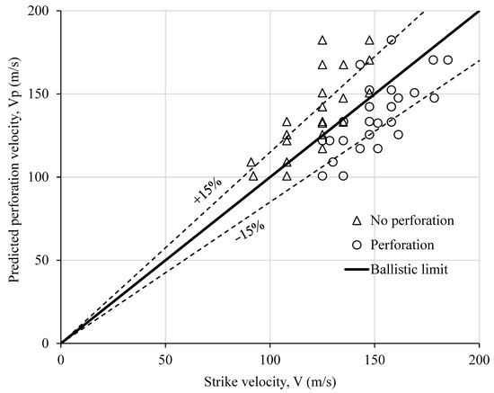
Figure 12.
Ballistic limit prediction based on quasi-static punching energy.
It is worth noting that the stress-strain pattern of the rebars determines the behavior of the reinforced concrete under the projectile impacts (at different strike velocities), especially when estimating the ballistic limit. This is because the state of stress in different rebars varies from elastic state to fracture. Moreover, the value of estimated from the quasi-static response is also dependent on the complete stress-strain pattern of rebars, as the post-peak response is also involved in the calculation of . Thus, it was not feasible to account for the difference in the material properties of the two types of rebars to achieve the equivalent reinforcement ratio.
6. Conclusions
In the present study, results of projectile impact tests on strengthened and unstrengthened singly and doubly reinforced concrete slabs having variable rebar spacing and concrete strength (normal and high strength concrete) were correlated with the quasi-static punching test results. The RC slabs were strengthened using externally bonded CFRP or TRM on the back face. The major conclusions derived from the study are:
- Each load-displacement curve in quasi-static punching shows two peak loads. While punching, a second peak load is formed by resistance provided by rebars on the back face and strengthening layers, if any.
- In general, CFRP strengthening improved the punching resistance of RC slabs more than TRM strengthening. The WWM involving the use of smaller diameter rebars at close spacing increases the punching resistance moderately.
- The enhancement in energy absorption in quasi-static punching due to the strengthening of singly reinforced slabs varies from 57–70% for CFRP and 20% to 59% for TRM. However, for doubly reinforced slabs, CFRP and TRM strengthening resulted in an 87–130% and 28–33% increase in energy absorption, respectively. The reduction in rebar spacing from 100 to 25 mm and keeping the same area of reinforcement in singly and doubly reinforced slabs caused 30–42% and 41–63% increase in energy absorption in punching, respectively.
- The back face scabbing and hence the generation of debris cloud and secondary projectiles got considerably reduced for strengthened and WWM reinforced slabs. TRM strengthening of RC slabs performed equally well or better than CFRP strengthening among the two strengthening schemes studied. The ballistic limit velocity was further increased by replacing the rebars with WWM.
- Based on the equation proposed for the ballistic limit for unstrengthened and strengthened (with CFRP or TRM) RC slabs, it is evident that the dynamic perforation energy is positively correlated with the energy needed for quasi-static punching. The prediction of the ballistic limit from the proposed equation matches well with the experimental results.
Author Contributions
Conceptualization, methodology, validation, formal analysis, writing—original draft, writing—review and editing, H.A. and N.S.; funding acquisition, T.A., H.A. and N.S.; writing—review and editing, A.A.; supervision, investigation, writing—review and editing, T.A. and Y.A.-S. All authors have read and agreed to the published version of the manuscript.
Funding
This research was funded by King Abdul-Aziz City for Science and Technology, Saudi Arabia, under National Plan for Science and Technology, grant number 14-ADV1056-02-R.
Data Availability Statement
Not applicable.
Acknowledgments
The authors gratefully acknowledge the financial grant (No.: 14-ADV1056-02-R) received from King Abdul-Aziz City for Science and Technology, Saudi Arabia, under National Plan for Science and Technology.
Conflicts of Interest
The authors declare no conflict of interest.
References
- Ma, W. Behavior of Aged Reinforced Concrete Columns under High Sustained Concentric and Eccentric Loads. Ph.D. Dissertation, University of Nevada, Las Vegas, NV, USA, 2021. [Google Scholar]
- Abdel-Kader, M.; Fouda, A. Effect of reinforcement on the response of concrete panels to impact of hard projectiles. Int. J. Impact Eng. 2014, 63, 1–17. [Google Scholar] [CrossRef]
- Li, J.; Wu, C.; Hao, H.; Su, Y. Experimental and numerical study on steel wire mesh reinforced concrete slab under contact explosion. Mater. Des. 2017, 116, 77–91. [Google Scholar] [CrossRef]
- Almusallam, T.; Siddiqui, N.; Iqbal, R.A.; Abbas, H. Response of hybrid-fiber reinforced concrete slabs to hard projectile impact. Int. J. Impact Eng. 2013, 58, 17–30. [Google Scholar] [CrossRef]
- Zineddin, M.; Krauthammer, T. Dynamic response and behavior of reinforced concrete slabs under impact loading. Int. J. Impact Eng. 2007, 34, 1517–1534. [Google Scholar] [CrossRef]
- Iqbal, M.A.; Kumar, V.; Mittal, A.K. Experimental and numerical studies on the drop impact resistance of prestressed concrete plates. Int. J. Impact Eng. 2019, 123, 98–117. [Google Scholar] [CrossRef]
- Xing, H.; Zhao, J.; Wu, G.; Ruan, D.; Dehkhoda, S.; Lu, G.; Zhang, Q. Perforation model of thin rock slab subjected to rigid projectile impact at an intermediate velocity. Int. J. Impact Eng. 2020, 139, 103536. [Google Scholar] [CrossRef]
- Wang, Z.-Y.; Guo, Q.-Q.; Hou, C.-C. Numerical study on the ballistic performance of prestressed concrete slabs subjected to hard missile impact. Int. J. Impact Eng. 2022, 168, 104318. [Google Scholar] [CrossRef]
- Gangolu, J.; Kumar, A.; Bhuyan, K.; Sharma, H. Performance-based probabilistic capacity models for reinforced concrete and prestressed concrete protective structures subjected to missile impact. Int. J. Impact Eng. 2022, 164, 104207. [Google Scholar] [CrossRef]
- Zhang, T.; Wu, H.; Huang, T.; Sheng, J.; Fang, Q.; Zhang, F. Penetration depth of RC panels subjected to the impact of aircraft engine missiles. Nucl. Eng. Des. 2018, 335, 44–53. [Google Scholar] [CrossRef]
- Baroth, J.; Briffaut, M.; Vu, D.; Malecot, Y.; Daudeville, L. Prediction of perforation into concrete accounting for saturation ratio influence at high confinement. Int. J. Impact Eng. 2021, 156, 103923. [Google Scholar] [CrossRef]
- Erki, M.A.; Heffernan, P.J. Reinforced concrete slabs externally strengthened with fibre reinforced plastics materials. In Proceedings of the 2nd International Symposium on Non-Metalic FRP Reinforcement for Concrete Structures (FRPRCS-2), Ghent, Belgium, 23–25 August 1995; Taerwe, L., Ed.; E & FN Spon: London, UK, 1995; pp. 509–516. [Google Scholar]
- Wang, J.W.; Tan, K.I. Punching shear behaviour of RC flat slabs externally strengthened with CFRP system. In Proceedings of the 5th International Conference on Fibre-Reinforced Plastic for Reinforced Concrete Structures (FRPRCS-5), Cambridge, UK, 16–18 July 2001; Thomas Telford: London, UK, 2001; Volume 2, pp. 997–1005. [Google Scholar]
- Binici, B.; Bayrak, O. Punching Shear Strengthening of Reinforced Concrete Flat Plates Using Carbon Fiber Reinforced Polymers. J. Struct. Eng. 2003, 129, 1173–1182. [Google Scholar] [CrossRef]
- Soudki, K.; El-Sayed, A.K.; Vanzwol, T. Strengthening of concrete slab-column connections using CFRP strips. J. King Saud Univ. Eng. Sci. 2012, 24, 25–33. [Google Scholar] [CrossRef]
- Chen, C.C.; Li, C.Y. Punching shear strength of reinforced concrete slabs strengthened with glass fiber-reinforced polymer laminates. ACI Struct. J. 2005, 102, 535. [Google Scholar]
- Al-Salloum, Y.A.; Siddiqui, N.A.; Elsanadedy, H.M.; Abadel, A.A.; Aqel, M.A. Textile-Reinforced Mortar versus FRP as Strengthening Material for Seismically Deficient RC Beam-Column Joints. J. Compos. Constr. 2011, 15, 920–933. [Google Scholar] [CrossRef]
- Alhaddad, M.S.; Siddiqui, N.A.; Abadel, A.A.; Alsayed, S.; Al-Salloum, Y.A. Numerical Investigations on the Seismic Behavior of FRP and TRM Upgraded RC Exterior Beam-Column Joints. J. Compos. Constr. 2012, 16, 308–321. [Google Scholar] [CrossRef]
- Abbas, H.; Siddiqui, N.A.; Almusallam, T.H.; Abadel, A.A.; Elsanadedy, H.; Al-Salloum, Y.A. Effect of rebar spacing on the behavior of concrete slabs under projectile impact. Struct. Eng. Mech. 2021, 77, 329–342. [Google Scholar]
- ACI Committee 318. Building Code Requirements for Structural Concrete (ACI 318-14) [and] Commentary on Building Code Requirements for Structural Concrete (ACI 318R-14); American Concrete Institute: Farmington Hills, MI, USA, 2014. [Google Scholar]
- ASTM A370; Standard Test Methods and Definitions for Mechanical Testing of Steel Products. ASTM International: West Conshohocken, PA, USA, 2017.
- Abbas, H.; Abadel, A.A.; Almusallam, T.; Al-Salloum, Y. Effect of CFRP and TRM Strengthening of RC Slabs on Punching Shear Strength. Lat. Am. J. Solids Struct. 2015, 12, 1616–1640. [Google Scholar] [CrossRef]
- Tai, Y.-S.; Tang, C.-C. Numerical simulation: The dynamic behavior of reinforced concrete plates under normal impact. Theor. Appl. Fract. Mech. 2006, 45, 117–127. [Google Scholar] [CrossRef]
- Xu, K.; Lu, Y. Numerical simulation study of spallation in reinforced concrete plates subjected to blast loading. Comput. Struct. 2006, 84, 431–438. [Google Scholar] [CrossRef]
- Li, Q.; Reid, S.; Wen, H.; Telford, A. Local impact effects of hard missiles on concrete targets. Int. J. Impact Eng. 2005, 32, 224–284. [Google Scholar] [CrossRef]
- Elsanadedy, H.M.; Abbas, H.; Al-Salloum, Y.A.; Almusallam, T.H. Prediction of Intermediate Crack Debonding Strain of Externally Bonded FRP Laminates in RC Beams and One-Way Slabs. J. Compos. Constr. 2014, 18, 04014008. [Google Scholar] [CrossRef]
Publisher’s Note: MDPI stays neutral with regard to jurisdictional claims in published maps and institutional affiliations. |
© 2022 by the authors. Licensee MDPI, Basel, Switzerland. This article is an open access article distributed under the terms and conditions of the Creative Commons Attribution (CC BY) license (https://creativecommons.org/licenses/by/4.0/).