Article

Corrosion-Induced Damage and Residual Strength of WC-Co,Ni Cemented Carbides: Influence of Microstructure and Corrosion Medium †

1
CIEFMA, Departament de Ciència dels Materials i Enginyeria Metal∙lúrgica, EEBE, Universitat Politècnica de Catalunya, 08019 Barcelona, Spain
2
Barcelona Research Center in Multiscale Science and Engineering, Universitat Politècnica de Catalunya, 08019 Barcelona, Spain
3
IMEM, Departament d’Enginyeria Química, EEBE, Universitat Politècnica de Catalunya, 08019 Barcelona, Spain
4
Hyperion Materials and Technologies, 08107 Martorelles, Spain
*
Author to whom correspondence should be addressed.
This paper is an extended version of our paper published in Euro PM 2018, Bilbao, Spain, 14–18 October 2018.
Metals 2019, 9(9), 1018; https://doi.org/10.3390/met9091018
Submission received: 30 July 2019 / Revised: 3 September 2019 / Accepted: 17 September 2019 / Published: 19 September 2019
(This article belongs to the Special Issue Design of Cemented Carbides and Cermet)

Abstract

:
The corrosion behavior of cemented carbides with binders of different chemical nature (Co and Ni) and carbides with distinct mean grain size (ultrafine and coarse) was studied. The investigation also included corrosion media (acidic and neutral solutions containing chlorides and an alkaline solution) as experimental variables. Immersion tests were performed to induce corrosion damage in a controlled way. Electrochemical parameters were measured together with a detailed inspection of the corroded surfaces. Microstructural influence on the tolerance to corrosion damage was evaluated in terms of residual strength. Results pointed out that corrosion rates were lower in the alkaline solution. In contrast, acidic media led to higher corrosion rates, especially for cemented carbides with Co regardless the influence of carbide mean grain size. Corrosion damage resulted in strength degradation due to the formation of surface corrosion pits in acidic solution. In neutral and alkaline solutions, much less pronounced effects were determined. Focused Ion Beam (FIB)/ Field Emission Scanning Electron Microscopy (FESEM) results revealed differences in corrosion-induced damage scenario. In acidic solution, corrosion starts at binder pool centers and evolves towards binder/WC interfaces. Meanwhile, corrosion in alkaline solution is initially located at binder/WC interfaces, and subsequently expands into the ceramic particles, developing a microcrack network inside this phase.

1. Introduction

Cemented carbides, usually referred to as hardmetals, are preeminent material choices for extremely demanding applications, such as cutting and forming tools, mechanical seals, and mining bits. The main reason behind this is the unique combination of hardness, toughness, and wear resistance they exhibit. It results from their two-phase interpenetrated network as well as the intrinsic properties of the ceramic particles and the metallic binder [1,2,3,4,5]. Many of the referred applications often imply exposure of cemented carbides tools and components to chemically aggressive media including a large variety of corrosive environments, such as lubricants, chemical and petrochemical products, as well as mine- and sea-water (e.g., References [6,7,8,9]).
Corrosion mechanisms in cemented carbides depend on a large number of factors, such as surface state, corrosive medium, microstructural assemblage, and binder chemical nature. It has been found that nickel, nickel-chromium, and nickel-cobalt binder exhibit higher corrosion resistance compared to plain cobalt one, especially in acidic and neutral media. Under these conditions, metallic binders are preferentially attacked, while ceramic phase is the one corroded in alkaline solution [10,11]. Regarding the influence of grain size, it is difficult to extract clear conclusions from the literature. While some authors report a negligible influence of the grain size on the corrosion behavior in acids [6], others have found a direct correlation between passive current density and grain size in acidic solutions [12]. The fact that neither materials nor the electrolytes were the same in these studies, increases the uncertainty about this issue.
Performance and reliability of engineering components depend on how service-like conditions may affect their properties. Several studies have shown detrimental corrosion effects on the effective wear resistance of cemented carbides, as a result of synergic interactions among different degradation phenomena [13,14,15]. Similar correlations have been reported regarding residual strength, measured under either monotonic or cyclic loads [16,17,18,19,20,21]. However, most of these works have focused on either one particular hardmetal grade or a specific corrosive medium. As a consequence, to draw generic relationships including microstructure and corrosive medium aspects is not possible. Following the above ideas, the corrosion-induced damage and the corresponding residual strength (tolerance) behavior of four microstructurally different cemented carbides exposed to three distinct corrosion media are studied here. In doing so, besides the mechanical response referred, electrochemical parameters are measured as well as corrosion damage scenario is documented and analyzed. Information gathered is expected to be useful for defining microstructural design guidelines on the basis of damage tolerance as a function of type of corrosive medium.

2. Materials and Methods

Four hardmetal grades with different binder and carbide mean grain size were studied. All materials were supplied by Hyperion Materials and Technologies. Hardness, fracture toughness and main microstructural characteristics including specimen designations, binder content (%wt.), mean grain size (dWC), contiguity (CWC) and binder mean free path (λbinder) are listed in Table 1. Mean grain size was measured following the linear intercept method, using field emission scanning electron microscopy (FESEM) micrographs. On the other hand, carbide contiguity and binder mean free path were deduced according to empirical relationships given in the literature [2,22]. A small amount of Cr3C2 (i.e., <1%wt.) was added in 10CoUF and 9NiF grades as grain growth inhibitor.
Corrosion behavior was studied on the basis of the electrochemical response of the studied grades in three different solutions: acidic (0.1M HCl), neutral containing chlorides (0.1M NaCl), and alkaline (0.1M NaOH). The electrochemical tests were carried out using a VersaStatTM II potentiostat-galvanostat (Princeton Applied Research, Oak Ridge, TN, USA.) and a standard three-electrode cell in which the test specimen was the working electrode (area: 1.0 cm2), a platinum wire was the counter electrode, and a silver/silver chloride electrode was used as the reference electrode. After immersion in the electrolyte, the open circuit potential was stabilized for 30 min. Subsequently, the samples were polarized into the cathodic region at –500 mV. Then, the potential was increased towards the anodic region with a scan rate of 600 mV/h in the positive direction up to 500 mV.
Immersion tests were performed to induce corrosion damage in a controlled way and to determine the corrosion rates by gravimetric analysis. These tests were done at room temperature in the same three solutions (stirred) as mentioned above. Weight loss was measured after immersion tests performed from 1 to 240 h. Before and after immersion tests, the specimens were hand-cleaned using soapy water, then ultrasonically cleaned for 15 min in ethanol, and subsequently dried in air. In this case, at least five samples were tested for each material and solution. The specimens were weighted using an electronic balance having a resolution of ±0.1 mg, and the corrosion rates were determined using Equation (1):
C o r r o s i o n ( mm / year ) = 87.6 ( w A ρ t )
where w is the weight loss in mg; A is the surface area of the specimen in cm2; ρ is the density of the material in g/cm3; and t is the corrosion time in hours.
After immersion tests, mechanical tests were carried out to assess the tolerance to corrosion-induced damage—measured in terms of residual flexural strength—as a function of microstructure and corrosion medium. Flexural strength (σr) was determined according to ASTM Standard C1161-13 by using a fully articulating jig fixture in a four-point bending configuration, with inner and outer spans of 20 and 40 mm respectively [25]. Measurements were done on beam-like specimens (with dimensions of 4 mm × 3 mm × 45 mm) whose longitudinal edges were beveled before testing for avoiding stress rising effects. A minimum of three specimens were tested for each corroded condition. Aiming to define the “baseline” intrinsic flexural strength for each hardmetal grade studied, the same tests were also conducted on uncorroded samples (eight tests per hardmetal grade). The equation used for the strength calculation can be expressed as [25]:
σ r = 3 P L 4 b d 2
where P is break force in N; L is outer span in mm; b is specimen width in mm; and d is specimen thickness in mm.
The mechanical study was complemented by fractographic inspection by means of optical microscopy and FESEM. For each specimen, fracture initiation sites were identified at low magnification; and then, strength-limiting flaws were further analyzed at higher magnifications. Finally, cross-sectional samples were prepared by Focused Ion Beam (FIB) milling, using a dual bean Workstation. They were used for evaluation of corrosion-induced damage at the subsurface level through FESEM imaging.

3. Results and Discussion

3.1. Corrosion Behavior

In immersion tests, the corrosion rates in acidic solution were higher for all studied cemented carbides grades compared to neutral and alkaline ones, as shown in Figure 1. Table 2 gives the corrosion rate values of investigated cemented carbides after immersion for 168 h in these three different media. Coarse-grained cobalt grade, 10CoC, displayed in each solution the highest values, while 9NiF showed the best corrosion resistance. The presence of small amount of chromium in 10CoUF grade together with the ultrafine microstructure proved to be more effective than the presence of 2%wt. of nickel in a coarse-grained cobalt grade, 10CoNiM. This result is in agreement with previous studies which pointed out that during sintering chromium dissolves into the binder, resulting in a beneficial effect against corrosion [26]. TEM analysis performed by Suttihiruangwong et al. [27] demonstrated the formation of a passivating Co-based chromium oxide layer film at the binder surface, which strongly decreased the rate dissolution of the binder, and hence improved the corrosion resistance of Cr-containing cemented carbides.
For all studied grades and solutions, the corrosion rates decreased with increasing immersion time. In acidic and alkaline solutions, the corrosion rates sharply decreased after the first 6–8 h of immersion, remaining constant beyond 24 h. At the beginning of corrosion tests, the higher corrosion rate may be attributed to the relatively large area of the alloy exposed to the corrosive media. As the immersion progresses, the generated corrosion products gradually cover the surface of the alloy, which reduces the contact area between the alloy and the corrosive medium, thereby reducing the corrosion rate. For these two solutions, no layer of corrosion products was observed at the surface. In neutral solution, the reduction of the corrosion rate as a function of immersion time was observed to be more gradual for the coarse-grained cobalt grades, 10CoC and 10CoNiM. In this case, the presence of chloride ions enhances the formation of a corrosion product layer which seems to slow down the dissolution of cobalt. This layer does not protect the material from corrosion, as chromium, but hinders the dissolution process of cobalt.
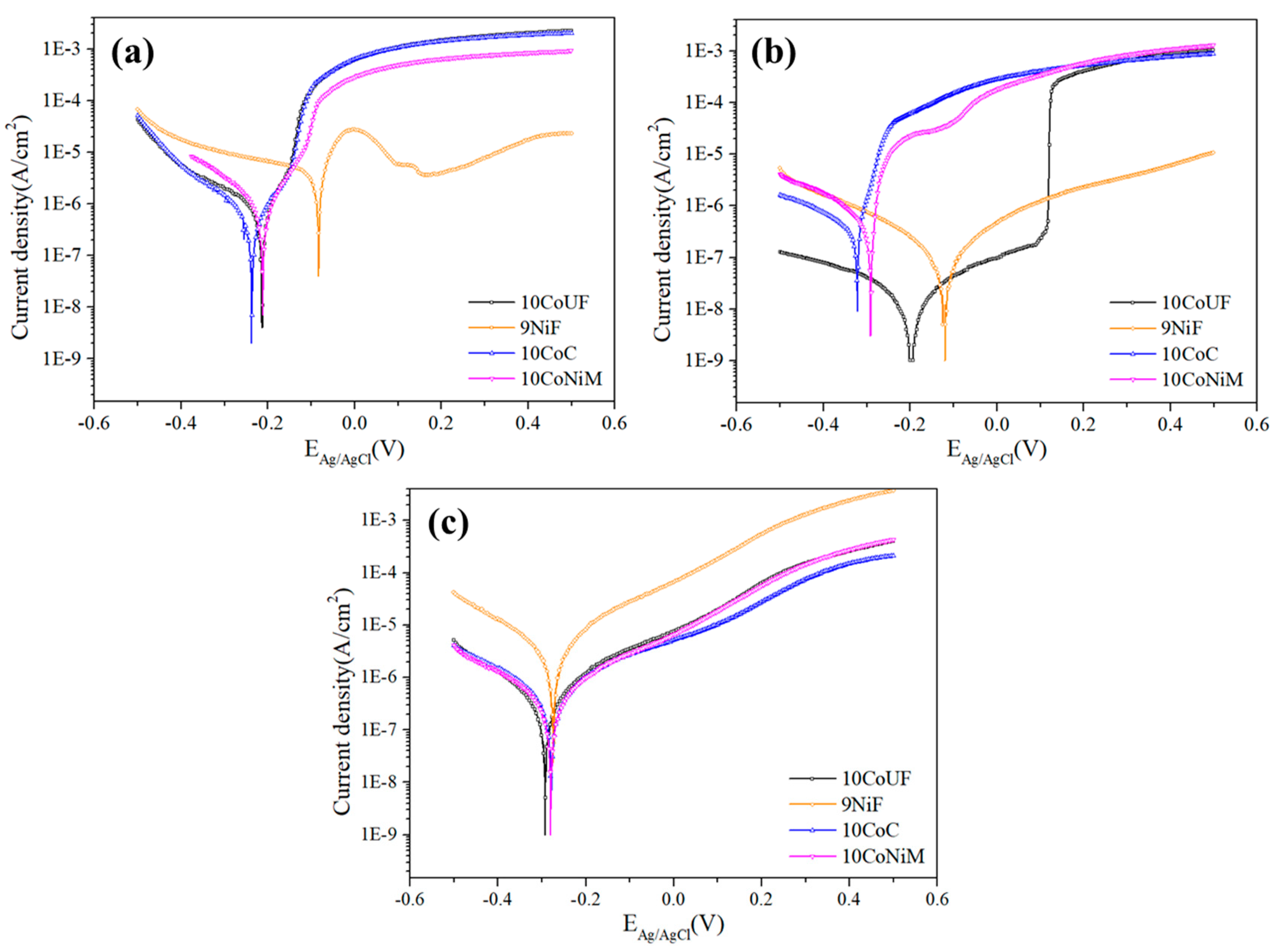
Figure 2 shows the obtained potentiodynamic polarization curves for the studied grades in the acidic, neutral and alkaline solutions. The electrochemical parameters measured for the studied cemented carbides are listed in Table 3. They include corrosion potential (Ecorr), corrosion current density (icorr) measured using the Tafel method, and critical current density (ic), which refers to the current density necessary to reach the passive or pseudo-passive potential. In acidic and neutral solution, the grade with nickel as a binder, 9NiF, clearly displayed the noblest corrosion potential. Meanwhile, coarse-grained cobalt grade, 10CoC, presented the most negative values. For this type of microstructure, the corrosion potential was shifted to more positive values with the presence of 2 wt.% of nickel as a binder, 10CoNiM. It is important to point out that although icorr is higher in acidic solutions for 9NiF, ic was at least one order of magnitude lower than for the rest of the cobalt grades. The addition of chromium in cobalt grades, 10CoUF, did not contribute to a better corrosion response. As can be seen in Table 3, the Ecorr is moved in the noble direction. Likely, the apparent transpassive region is shifted to higher potentials and lower ic, compared to the other grades. However, at about +100 mV, the self-passivating layer underwent pitting corrosion and the surface response became similar to the other cobalt grades. This phenomenon is supposed to be related to the fracture of the protective oxide film referred above. Nevertheless, future works are needed to corroborate it. Regarding the alkaline solution, no significant differences were observed among cobalt grades. In this media, where the ceramic phase is easily corroded [10,11], the nickel grade showed the highest current densities.

3.2. Residual Strength of Corroded Hardmetals

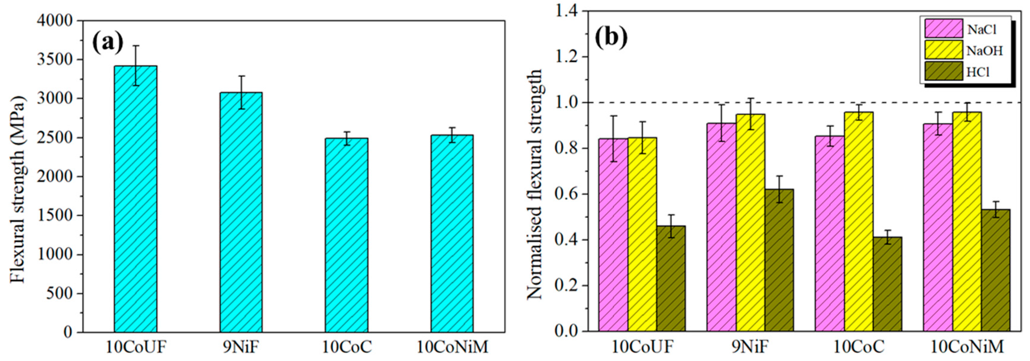
Retained strength was measured using samples subjected to immersion tests of 240 h in acidic, neutral and alkaline solutions respectively (Figure 3b). Values are plotted as normalized strength loss, using as reference baseline the strength exhibited by uncorroded specimens (Figure 3a). As it can be observed, each studied corrosive medium induces relatively different strength losses, most likely related to significant differences in the size and geometry of corrosion-induced damage acting as critical flaws for fracture. HCl solution was found to be the most aggressive medium, i.e., flexural strength for all studied grades, including the one with nickel as a binder, was significantly lessened. The highest strength loss, 60% approximately, was observed for 10CoC. Meanwhile, for neutral and alkaline solutions, retained strength was at least 80% in the worst-case scenario.
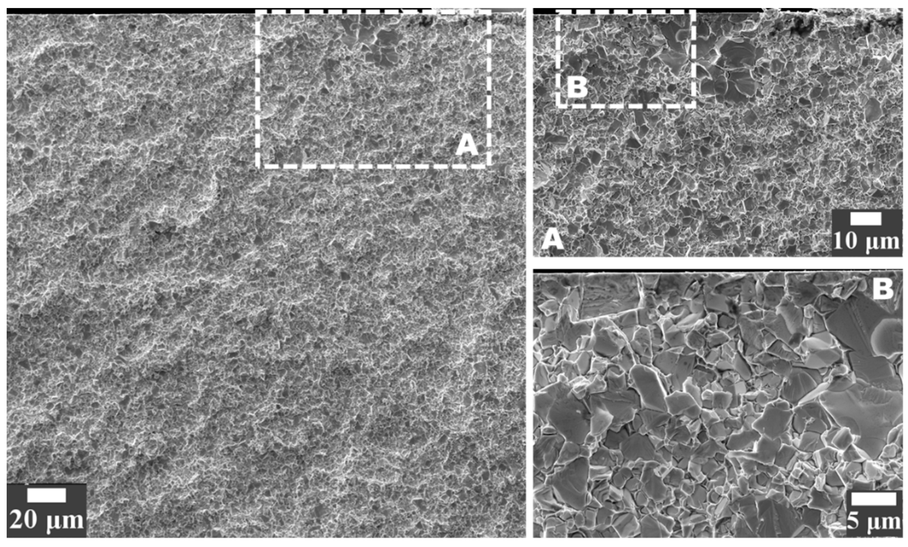
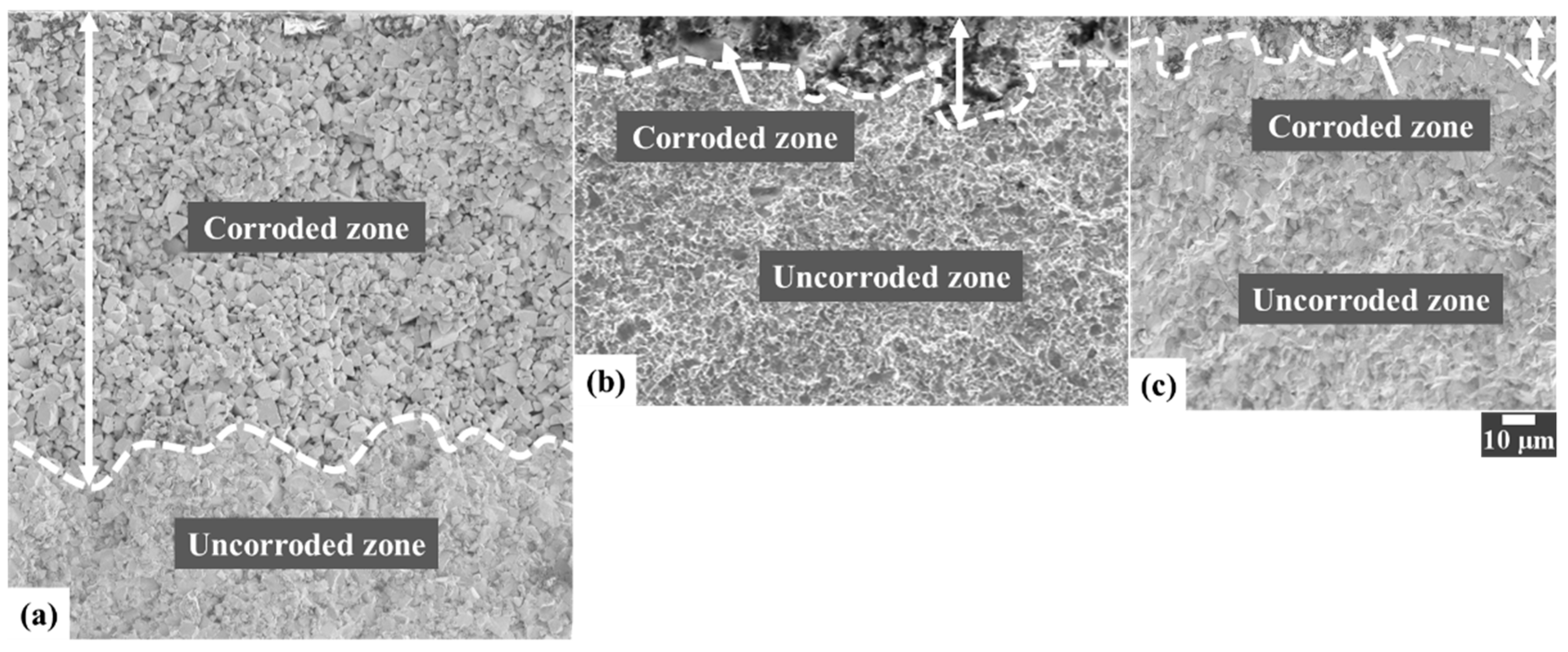
Aiming to analyze corrosion-induced damage promoting failure, a detailed inspection of fractured surfaces was conducted by means of FESEM. In doing so, Figure 4 shows the fracture initiation sites that were identified at low magnification together with the corresponding high magnification images showing the strength-limiting flaws, in which corrosion pits and binderless carbide agglomerate act as starting locations for subcritical crack growth until they reach a critical size where unstable fracture takes place. Furthermore, the observations revealed clear differences between the corrosion-induced damage as a function of the pH solution. In this sense, the affected depth from the surface for 10CoC in acidic media was about 150 μm, Figure 5a, followed by the corroded zones from neutral and alkaline medias, where the affected depths were close to 30 and 20 μm, respectively, as the maximum value, Figure 5b,c. It reveals that corrosion affected zone act as critical points for starting fracture, and the strength degradation shows a significant dependence on the depth of the corroded zone. A more pronounced deterioration in the flexural strength is discerned as the corroded zone gets deeper.
Regarding carbide grain size in the neutral and alkaline solutions, the ultrafine-sized studied grade was much more affected by corrosion-induced damage than the coarser ones. As reported in previous investigations, sharp corrosion pits are formed in ultrafine-sized cemented carbides as immersion time increases, which have a much more pronounced stress rising effect. Consequently, higher strength loss was expected for ultrafine grades [19,20].

3.3. FIB/FESEM Characterization of Corrosion-Induced Damage

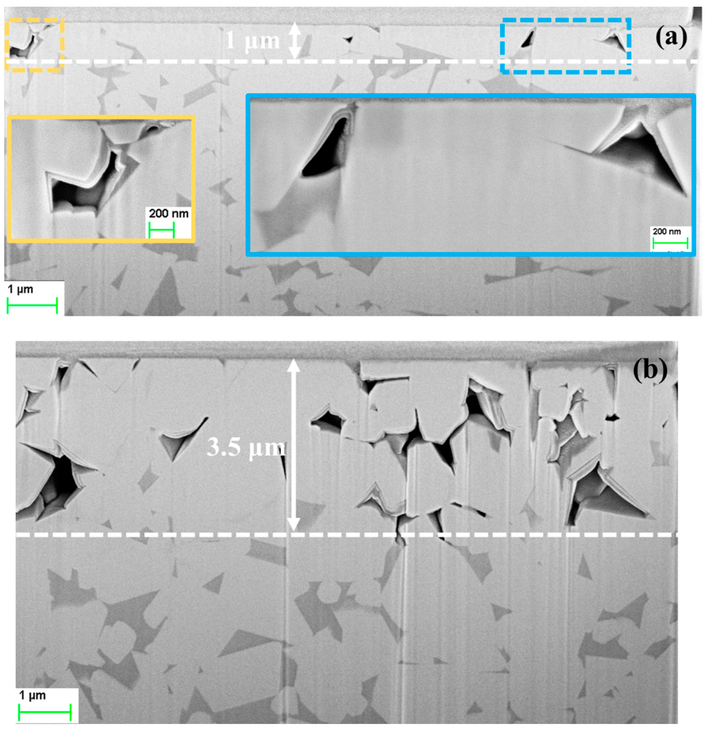
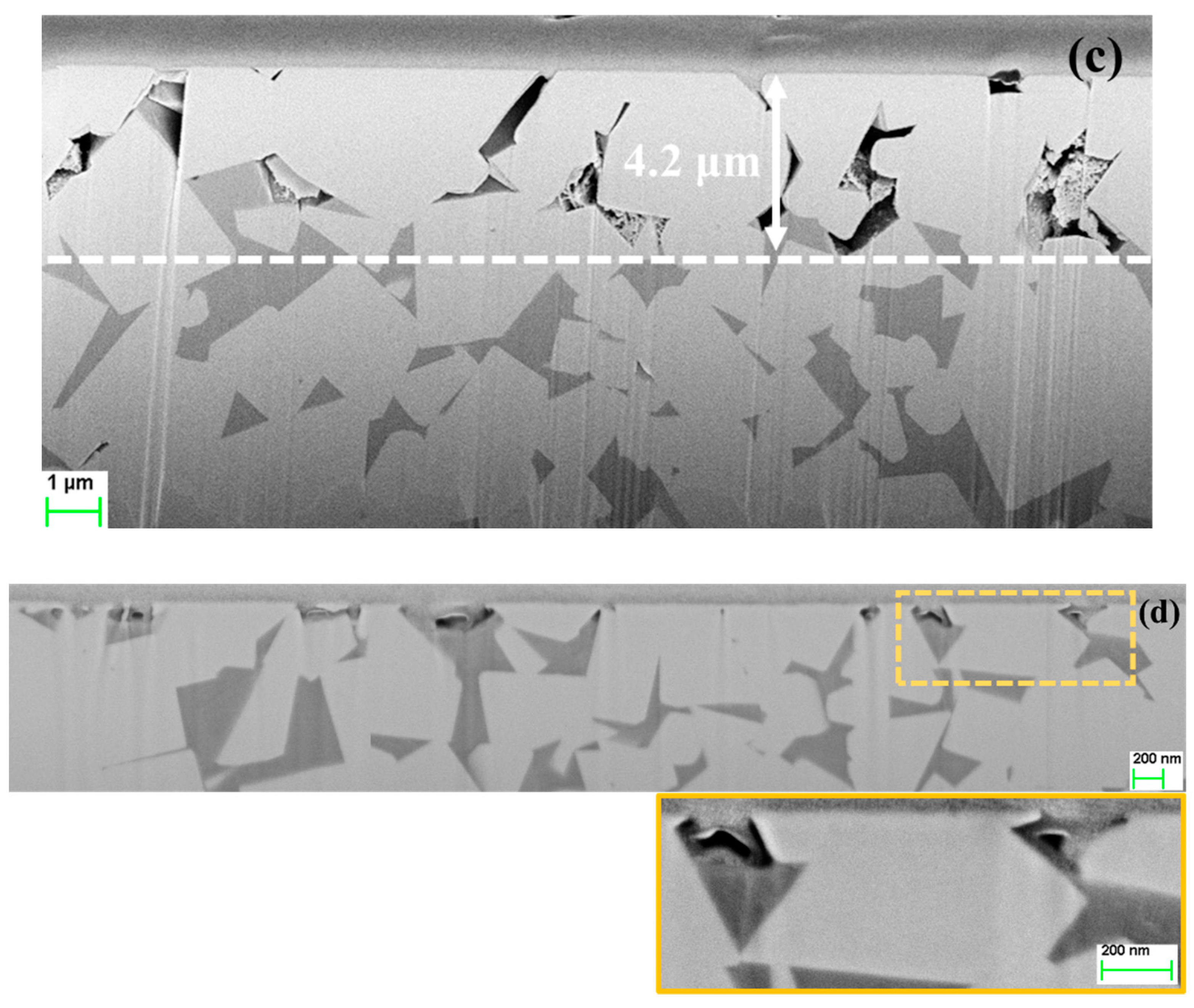
A detailed inspection of transversal cut micrographs was conducted for all grades in the studied media. As demonstrated in previous studies by the authors [19,20], the dissolution of metallic binder in neutral solutions takes place in the core of binder pools rather than at the binder/carbide interface. According to Figure 6, such damage emergence and evolution may be directly extrapolated to acidic solutions. Here, the dissolution of metallic binders started from the center towards the carbide/binder interface, independent of binder chemical nature (Co, Ni or CoNi) or grain size (coarse, fine or ultrafine). Within this context, such observations yield further support to the hypothesis that binder dissolution process is related to tensile thermal residual stress (TRS) state. On the other hand, they would discard the hypothesis of Cr-enrichment effects at binder/WC interfaces [26,27,28,29]. TRS state emerges during cooling from sintering temperature, due to the large difference on the coefficients of thermal expansion between the carbide and binder phases. Indeed, Co has a coefficient of thermal expansion of about twice that of WC, and consequently the binder phase is in tension while the WC particles are in compression [30,31]. Therefore, the maximum tensile TRS are located in the center of the binder pools, and consequently, stress corrosion effects are to be expected in these areas.
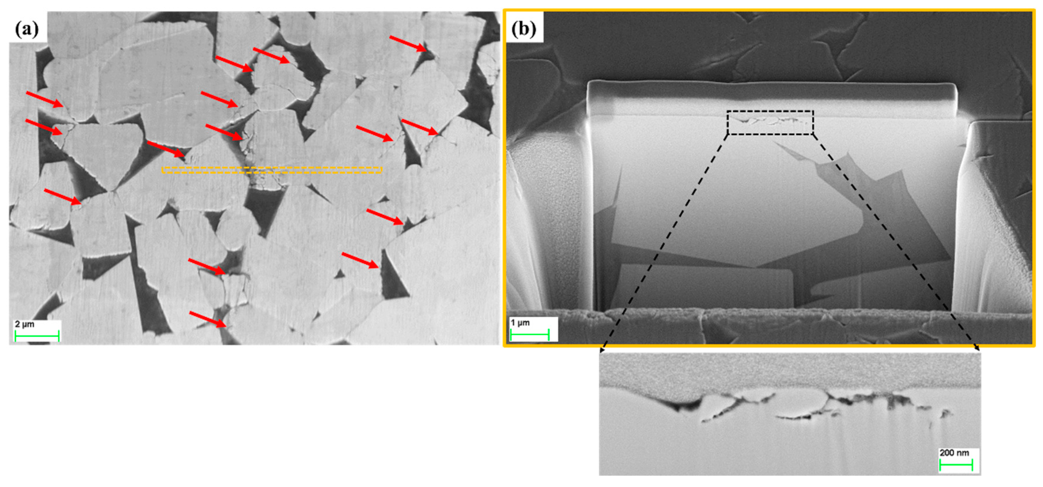
It is well known that in alkaline solutions WC–Co cemented carbides show a different behavior compared to acidic or neutral solutions. In the former case, corrosion properties are controlled by the corrosion resistance of the WC grains [15,21,32,33]. In this work, exhaustive observations have been carried out in WC grains at increasing immersion time in 0.1 M NaOH. At low time exposures, the degradation of the WC grains has been discerned to start at the binder/WC interface which leaded to the formation of microcracks and their growth inside WC grains at increasing dwell time, Figure 7.

4. Conclusions

In this study, corrosion behavior was studied together with the effect of the corrosion-induced damage on residual strength of cemented carbides with different binders and carbide grain size by immersing them in acidic, neutral and alkaline solutions. The following conclusions may be drawn:
(1)
Electrochemical and immersion tests revealed that nickel binder displays more noble corrosion potential and critical current density compared to cobalt grades in acidic and neutral solutions containing chlorides. In these conditions, the presence of small amounts of chromium improves more the corrosion resistance of the materials than mixing nickel and cobalt as a binder. No significant differences among studied grades were observed in alkaline solution.
(2)
Corrosion damage resulted in strength degradation on the basis of stress rising effects associated with the formation of surface corrosion pits in acidic solution for all studied grades. In neutral and alkaline solutions, corrosion effects on residual strength are less pronounced. Under these conditions, the grade more affected by exposure to corrosion medium is the ultrafine one.
(3)
In acidic solution, the binder was preferentially attacked. The binder dissolution started from the center of binder pools, independent of binder chemical nature, and spreads to the edges until binder phase was completely consumed. In alkaline solution, corrosion process was initially located at the binder/WC interface. As exposure time increased, degradation evolved into microcracks which propagated inside the WC phase, yielding finally a fragmented-like scenario.

Author Contributions

Y.Z., G.F., E.A., O.L. and L.L. conceived and designed the experiments; Y.Z. performed the experiments; Y.Z. analyzed the data; O.L., E.A. and L.L. contributed reagents/materials/analysis tools; Y.Z., G.F. and L.L. wrote the paper.

Funding

This work was financially supported by the collaborative Industry-University program between Hyperion Materials & Technologies and Universitat Politècnica de Catalunya, and partly funded by the Spanish Ministerio de Economía y Competividad through Grant MAT2015-70780-C4-3-P (MINECO/FEDER).

Acknowledgments

Yafeng Zheng acknowledges the Ph.D. scholarship received from China Scholarship Council.

Conflicts of Interest

The authors declare no conflict of interest.

References

  1. Exner, H.E. Physical and chemical nature of cemented carbides. Int. Met. Rev. 1979, 24, 149–173. [Google Scholar] [CrossRef]
  2. Roebuck, B.; Almond, E.A. Deformation and fracture processes and the physical metallurgy of WC-Co hardmetals. Int. Mater. Rev. 1988, 33, 90–110. [Google Scholar] [CrossRef]
  3. Upadhyaya, G.S. Materials science of cemented carbides-an overview. Mater. Des. 2001, 22, 483–489. [Google Scholar] [CrossRef]
  4. Roa, J.J.; Jiménez-Piqué, E.; Verge, C.; Tarragó, J.M.; Mateo, A.; Fair, J.; Llanes, L. Intrinsic hardness of constitutive phases in WC-Co composites: Nanoindentation testing, statistical analysis, WC crystal orientation effects and flow stress for the constrained metallic binder. J. Eur. Ceram. Soc. 2015, 35, 3419–3425. [Google Scholar] [CrossRef]
  5. Jiménez-Piqué, E.; Turon-Vinas, M.; Chen, H.; Trifonov, T.; Fair, J.; Tarrés, E.; Llanes, L. Focused ion beam tomography of WC-Co cemented carbides. Int. J. Refract. Met. Hard Mater. 2017, 67, 9–17. [Google Scholar] [CrossRef] [Green Version]
  6. Human, A.M.; Exner, H.E. The relationship between electrochemical behaviour and in-service corrosion of WC based cemented carbides. Int. J. Refract. Met. Hard Mater. 1997, 15, 65–71. [Google Scholar] [CrossRef]
  7. Bozzini, B.; De Gaudenzi, G.P.; Serra, M.; Fanigliulo, A.; Bogani, F. Corrosion behaviour of WC-Co based hardmetal in neutral chloride and acid sulphate media. Mater. Corros. 2002, 53, 328–334. [Google Scholar] [CrossRef]
  8. Lu, R.; Minarro, L.; Su, Y.Y.; Shemenski, R.M. Failure mechanism of cemented tungsten carbide dies in wet drawing process of steel cord filament. Int. J. Refract. Met. Hard Mater. 2008, 26, 589–600. [Google Scholar] [CrossRef]
  9. Bozzini, B.; Busson, B.; De Gaudenzi, G.P.; Humbert, C.; Tadjeddine, A. Corrosion of cemented carbide grades in petrochemical slurries. Part I—Electrochemical adsorption of CN¯, SCN¯ and MBT: A study based on in situ SFG. Int. J. Refract. Met. Hard Mater. 2016, 60, 37–51. [Google Scholar] [CrossRef]
  10. Konadu, D.S.; Van Der Merwe, J.; Potgieter, J.H.; Potgieter-Vermaak, S.; Machio, C.N. The corrosion behaviour of WC-VC-Co hardmetals in acidic media. Corros. Sci. 2001, 52, 3118–3125. [Google Scholar] [CrossRef]
  11. Kellner, F.J.J.; Hildebrand, H.; Virtanen, S. Effect of WC grain size on the corrosion behaviour of WC-Co based hardmetals in alkaline solutions. Int. J. Refract. Met. Hard Mater. 2009, 27, 806–812. [Google Scholar] [CrossRef]
  12. Tomlinson, W.J.; Ayerst, N.J. Anodic polarization and corrosion of WC-Co hardmetals containing small amounts of Cr3C2 and/or VC. J. Mater. Sci. 1989, 24, 2348–2354. [Google Scholar] [CrossRef]
  13. Engqvist, H.; Beste, U.; Axén, N. The influence of pH on sliding wear of WC-based materials. Int. J. Refract. Met. Hard Mater. 2000, 18, 103–109. [Google Scholar] [CrossRef]
  14. Gant, A.J.; Gee, M.G.; May, A.T. The evaluation of tribo-corrosion synergy for WC-Co hardmetals in low stress abrasion. Wear 2004, 256, 500–516. [Google Scholar] [CrossRef]
  15. Thakare, M.R.; Wharton, J.A.; Wood, R.J.K.; Menger, C. Exposure effects of alkaline drilling fluid on the microscale abrasion-corrosion of WC-based hardmetals. Wear 2007, 263, 125–136. [Google Scholar] [CrossRef]
  16. Tomlinson, W.J.; Molyneux, I.D. Corrosion, erosion-corrosion, and the flexural strength of WC-Co hardmetals. J. Mater. Sci. 1991, 26, 1605–1608. [Google Scholar] [CrossRef]
  17. Pugsley, V.A.; Korn, G.; Luyckx, S.; Sockel, H.G.; Heinrich, W.; Wolf, M.; Feld, H.; Schulte, R. The influence of a corrosive wood-cutting environment on the mechanical properties of hardmetal tools. Int. J. Refract. Met. Hard Mater. 2001, 19, 311–318. [Google Scholar] [CrossRef]
  18. Pugsley, V.A.; Sockel, H.G. Corrosion fatigue of cemented carbide cutting tool materials. Mater. Sci. Eng. A. 2004, 366, 87–95. [Google Scholar] [CrossRef]
  19. Tarragó, J.M.; Fargas, G.; Jimenez-Piqué, E.; Felip, A.; Isern, L.; Coureaux, D.; Roa, J.J.; Al-Dawery, I.; Fair, J.; Llanes, L. Corrosion damage in WC-Co cemented carbides: Residual strength assessment and 3D FIB-FESEM tomography characterization. Powder Metall. 2014, 57, 324–330. [Google Scholar] [CrossRef]
  20. Tarragó, J.M.; Fargas, G.; Isern, L.; Dorvlo, S.; Llanes, L. Microstructural influence on tolerance to corrosion-induced damage in hardmetals. Mater. Des. 2016, 111, 36–43. [Google Scholar] [CrossRef] [Green Version]
  21. Tang, W.; Zhang, L.; Chen, Y.; Zhang, H.; Zhou, L. Corrosion and strength degradation behaviors of binderless WC material and WC-Co hardmetal in alkaline solution: A comparative investigation. Int. J. Refract. Met. Hard Mater. 2017, 68, 1–8. [Google Scholar] [CrossRef]
  22. Tarragó, J.M.; Coureaux, D.; Torres, Y.; Yu, F.; Al-Dawery, I.; Llanes, L. Implementation of an effective time saving two-stage methodology for microstructural characterization of cemented carbides. Int. J. Refract. Met. Hard Mater. 2016, 55, 80–86. [Google Scholar] [CrossRef]
  23. Tarragó, J.M.; Dorvlo, S.; Esteve, J.; Llanes, L. Influence of the microstructure on the thermal shock behavior of cemented carbides. Ceram. Int. 2016, 42, 12701–12708. [Google Scholar]
  24. Tarragó, J.M.; Roa, J.J.; Valle, V.; Marshall, J.M.; Llanes, L. Fracture and fatigue behavior of WC-Co and WC-CoNi cemented carbides. Int. J. Refract. Met. Hard Mater. 2015, 49, 184–191. [Google Scholar] [CrossRef]
  25. ASTM C1161-13. Standard Test Method for Flexural Strength of Advanced Ceramics at Ambient Temperature; ASTM International: West Conshohocken, PA, USA, 2013. [Google Scholar]
  26. Sutthiruangwong, S.; Mori, G.; Kösters, R. Passivity and pseudopassivity of cemented carbides. Int. J. Refrac. Met. Hard Mater. 2005, 23, 129–136. [Google Scholar] [CrossRef]
  27. Sutthiruangwong, S.; Mori, G. Corrosion properties of Co-based cemented carbides in acidic solutions. Int. J. Refrac. Met. Hard Mater. 2003, 21, 135–145. [Google Scholar] [CrossRef]
  28. Schnyder, B.; Stössel-Sittig, C.; Kötz, R.; Hochstrasser-Kurz, S.; Virtanen, S.; Jaeggi, C. Investigation of the electrochemical behaviour of WC-Co hardmetal with electrochemical and surface analytical methods. Surf. Sci. 2004, 566, 1240–1245. [Google Scholar] [CrossRef]
  29. Henjered, A.; Hellsing, M.; Andrén, H.O.; Nordén, H. Quantitative microanalysis of carbide/carbide interfaces in WC-Co-base cemented carbides. Mater. Sci. Technol. 1986, 8, 847–855. [Google Scholar] [CrossRef]
  30. Krawitz, A.D.; Drake, E.F.; Clausen, B. The role of residual stress in the tension and compression response of WC-Ni. Mater. Sci. Eng. A. 2010, 527, 3595–3601. [Google Scholar] [CrossRef]
  31. Krawitz, A.; Drake, E. Residual stresses in cemented carbides—An overview. Int. J. Refract. Met. Hard Mater. 2015, 49, 27–35. [Google Scholar] [CrossRef]
  32. Hochstrasser-Kurz, S.; Reiss, D.; Suter, T.; Latkoczy, C.; Günther, D.; Virtanen, S.; Schmutz, P. ICP-MS, SKPFM, XPS, and microcapillary investigation of the local corrosion mechanisms of WC-Co hardmetal. J. Electrochem. Soc. 2008, 155, C415–C426. [Google Scholar] [CrossRef]
  33. Lin, N.; He, Y.; Wu, C.; Liu, S.; Xiao, X.; Jiang, Y. Influence of TiC additions on the corrosion behavior of WC-Co hardmetals in alkaline solution. Int. J. Refract. Met. Hard Mater. 2014, 46, 52–57. [Google Scholar] [CrossRef]
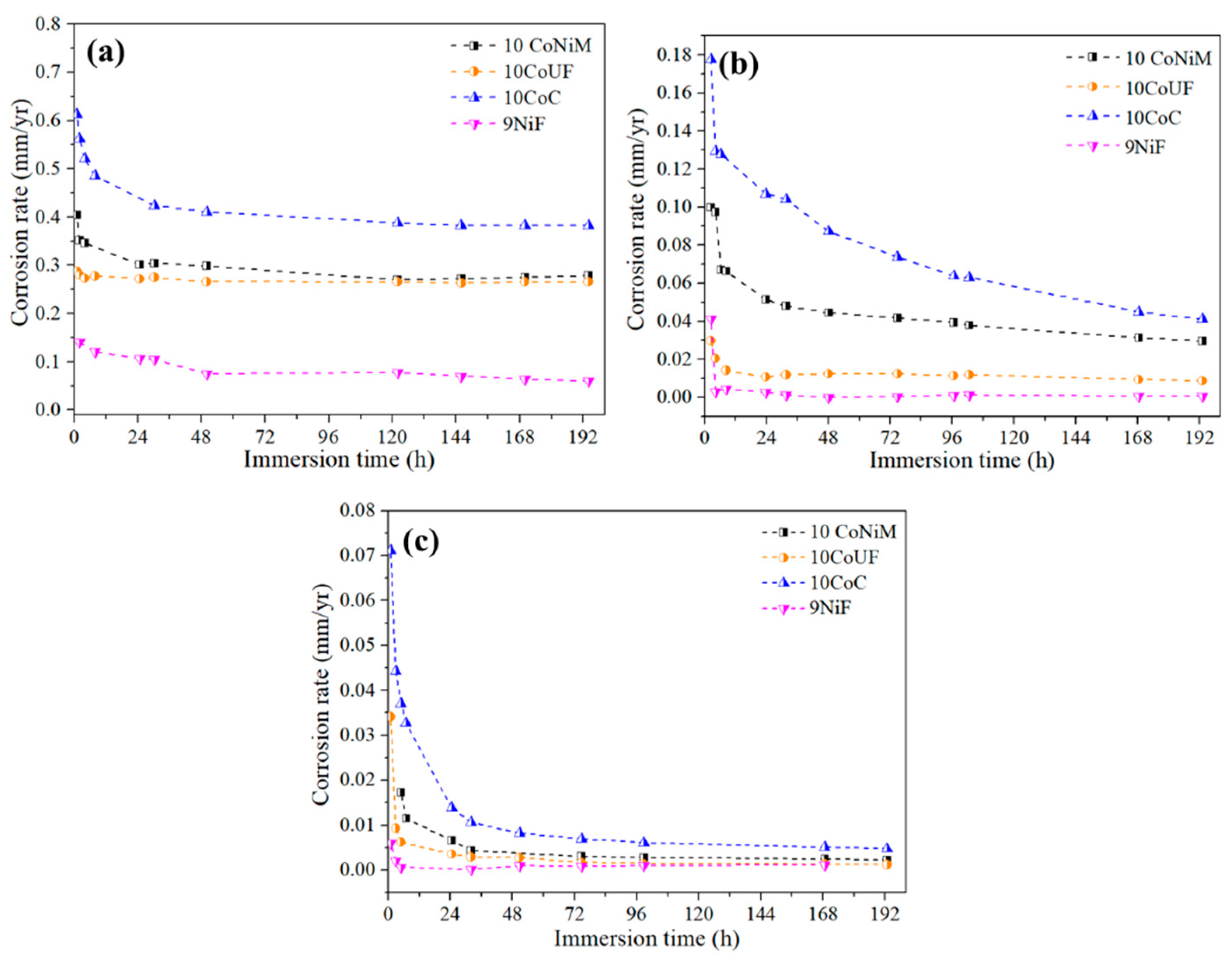
Figure 1. Corrosion rates as a function of immersion time for the studied cemented carbides in different solutions: (a) 0.1M HCl, (b) 0.1M NaCl and (c) 0.1M NaOH.
Metals 09 01018 g001
Figure 2. Potentiodynamic polarization curves of studied cemented carbide grades in: (a) 0.1M HCl, (b) 0.1M NaCl and (c) 0.1M NaOH.
Metals 09 01018 g002
Figure 3. (a) Flexural strength of uncorroded specimens, and (b) normalized retained strength for the studied materials in different corrosive media where strength of uncorroded specimens is used as reference baseline.
Metals 09 01018 g003
Figure 4. Example of a critical flaw (corrosion pits and binderless carbide agglomerate) that originates fracture in 10CoNiM grade corroded for 240 h.
Metals 09 01018 g004
Figure 5. Critical corrosion damage promoting failure in different corrosive solutions for 240 h for studied cemented carbides: (a) 10CoC in HCl, (b) 10CoC in NaCl, (c) 10CoC in NaOH.
Metals 09 01018 g005
Figure 6. Micrographs showing corrosion damage-microstructure interactions on cross-section for the studied corroded grades in 0.1M HCl solution: (a) 9NiF (6 h), (b) 10CoNiM (6 h), (c) 10CoC (6 h) and (d) 10CoUF (5 min).
Metals 09 01018 g006aMetals 09 01018 g006b
Figure 7. Micrographs showing corrosion damage-microstructure interactions for 10CoC grade corroded in 0.1M NaOH during 240 h.
Metals 09 01018 g007
Table 1. Microstructural parameters, hardness and fracture toughness for the investigated cemented carbides [20,23,24].
Specimen Code%wt. Co%wt. NidWC (µm)CWCλbinder (µm)HV30 (GPa)KIc (MPa)
10CoUF10-0.39 ± 0.190.46 ± 0.060.16 ± 0.0615.7 ± 0.610.4 ± 0.3
10CoC10-2.33 ± 1.380.31 ± 0.110.68 ± 0.4811.4 ± 0.215.8 ± 0.3
10CoNiM821.44 ± 0.860.38 ± 0.080.47 ± 0.3011.6 ± 0.115.3 ± 0.3
9NiF-90.83 ± 0.490.44 ± 0.080.29 ± 0.1813.2 ± 0.211.5 ± 0.2
Table 2. Corrosion rates of investigated cemented carbides after the immersion for 168 h.
Specimen CodeCorrosion Rate (mm/y)
0.1M HCl0.1M NaCl0.1M NaOH
10CoNiM2.8 × 10−12.96 × 10−22.23 × 10−3
10CoUF2.7 × 10−18.67 × 10−31.19 × 10−3
10CoC3.8 × 10−14.12 × 10−24.77 × 10−3
9NiF5.97 × 10−24.76 × 10−41.09 × 10−3
Table 3. Electrochemical corrosion parameters of studied cemented carbide grades in acidic, neutral and alkaline solutions.
Corrosive MediaSpecimen CodeEcorr (V)icorr (A/cm2)ic (A/cm2)
0.1M HCl10CoUF−0.2131.05 × 10−61.90 × 10⁻³
10CoC−0.2379.27 × 10−71.90 × 10⁻³
10CoNiM−0.2121.30 × 10−68.92 × 10⁻⁴
9NiF−0.0841.54 × 10−52.11 × 10⁻⁴
0.1M NaCl10CoUF−0.1967.38 × 10−82.21 × 10⁻⁷
10CoC−0.3225.05 × 10−63.67 × 10⁻⁴
10CoNiM−0.2915.22 × 10−62.07 × 10⁻⁴
9NiF−0.1245.20 × 10−7-
0.1M NaOH10CoUF−0.2921.19 × 10−6-
10CoC−0.2781.12 × 10−6-
10CoNiM−0.2791.02 × 10−6-
9NiF−0.2741.20 × 10−5-