Abstract
The effect of ultra-fast heating on the microstructures of steel has been thoroughly studied over the last year as it imposes a suitable alternative for the production of ultra high strength steel grades. Rapid reheating followed by quenching leads to fine-grained mixed microstructures. This way the desirable strength/ductility ratio can be achieved while the use of costly alloying elements is significantly reduced. The current work focuses on the effect of ultra-fast heating on commercial dual phase grades for use in the automotive industry. Here, a cold-rolled, low-carbon, medium-manganese steel was treated with a rapid heating rate of 780 °C/s to an intercritical peak temperature (760 °C), followed by subsequent quenching. For comparison, a conventionally heated sample was studied with a heating rate of 10 °C/s. The initial microstructure of both sets of samples consisted of ferrite, pearlite and martensite. It is found that the very short heating time impedes the dissolution of cementite and leads to an interface-controlled α → γ transformation. The undissolved cementite affects the grain size of the parent austenite grains and of the microstructural constituents after quenching. The final microstructure consists of ferrite and martensite in a 4/1 ratio, undissolved cementite and traces of austenite while the presence of bainite is possible. Finally, it is shown that the texture is not strongly affected during ultra-fast heating, and the recovery and recrystallization of ferrite are taking place simultaneously with the α → γ transformation.
1. Introduction
Over the last decades, the advanced high strength steels (AHSS) and ultra high strength steels (UHSS) [1,2,3,4] have taken over the automotive industry, as they impose the best solution for the ever-demanding need to produce better materials. Their success lies on the fact that they combine the effects of their chemical composition and thermal processing in order to achieve the desired strength/ductility ratio. Some of these grades achieve the desired properties thanks to alloying elements such as carbon, aluminum and manganese while other grades rely on phase transformation effects such as the transformation induced plasticity (TRIP) effect. Nevertheless, it is well known that the mechanical properties of all these grades are improved with the refinement of the microstructure.
It is safe to assume that from the AHSS grades, the dual phase steel grades are the most commonly used in the production of automotive parts. These grades rely on the ratio of martensite and ferrite for the achievement of the desired properties. The current work focuses on the production of such grades via ultra-fast heating (UFH). This heating treatment was first introduced by Cola et al. and Lolla et al. [5,6,7,8] and since it has been thoroughly studied over the last years. Papaefthymiou et al. [9] have shown that the UFH of medium carbon CrMo steels results in a multiphase fine microstructure consisting of martensite, bainite, undissolved cementite and retained austenite with grain average diameter less than 2 μm. The reason is that the ferrite to austenite phase transformation during ultra-fast heating creates chemically and structurally (morphologically) heterogeneous austenite with very fine grains, which transform after quenching to mixtures of bainite and martensite, while finely dispersed carbides remain partly dissolved or in their initial condition [10]. The presence of bainite in the microstructure was studied also by Banis et al. [11] and Cerda et al. [12]. They have shown the refinement of the prior austenite grains and inhomogeneous chemical composition can enable formation of bainite during quenching. Papaefthymiou et al. [13] and Bouzouni et al. [14,15] studied the kinetics of the carbide dissolution in a UFH steel. They observed partial dissolution of carbides despite short-range diffusion and ultrashort annealing time. The rate of carbide dissolution depends on the segregation of substitutional elements (Cr, Mn, Mo). Kaluba et al. [16,17] and Aaronson et al. [18] claimed that a massive transformation takes place during UFH. This α → γ transformation takes place without carbon enrichment of austenite, as there is no sufficient heating time for the dissolution of carbides and carbon diffusion. According to this massive transformation mechanism, the austenite nucleation takes place with a supposed bainitic transformation mechanism, which is not controlled by the carbon distribution and diffusion in the microstructure but by the movement of the interfaces. In this case, the driving force for the nucleation is the concentration gradient of carbon within the ferrite grains and its segregation on the grain boundaries creating a difference in the Gibbs free energy (ΔG) making this transformation thermodynamically possible. This was supported in the work of Savran [19] and Cerda et al. [20]. The presence of substitutional atoms, such as Cr and Mn, also tend to segregate at the interfaces modifying the local equilibrium [21,22,23,24,25,26]. Cerda et al. [26,27] have also thoroughly studied the effect of the heating rate on the recrystallization of ferrite. Their research has shown that the onset of ferrite recrystallization is shifted to higher temperatures with increasing heating rate. This means that the recrystallization process has not finished as the Ac1 temperature is reached and it is overlapping the austenitization process. Therefore, depending on the heating rate and the peak temperature, different fractions of recovered ferrite are expected in the microstructure. Concerning the grain size, according to Papaefthymiou et al. [9], significant heterogeneity is expected in the size of the prior austenite grains (PAGs). As the γ to α transformation takes place in the PAG boundaries depending on their orientation relationship [28], smaller PAGs will lead to increased fraction of grain boundaries and thus increased possible nucleation sites for the γ to α (martensite/bainite) transformation.
The scope of this article is an overall analysis of the microstructure evolution of a low carbon, medium manganese steel subjected to ultra-fast heat treatment in the intercritical region. The study is focused on the microstructural constituents, their grain size and crystallographic texture. Comparison of this analysis with a conventionally heat-treated sample is imperative in order to better understand the phenomena that take place.
2. Materials and Methods
In order to examine the microstructure evolution under ultra-fast heat treatment a cold-rolled, low carbon, medium manganese steel was used. The chemical composition can be seen in Table 1.

Table 1.
The chemical composition in wt. % of the studied steel.
Controlled-heating experiments were performed using a Gleeble 3800 Thermo-Mechanical Simulator (Dynamic Systems Inc., Poestenkill, NY, USA). Gleeble systems are based on resistance heating. Alternating electrical current is passed directly through the specimen resulting in its heating via the Joule effect. Extremely rapid and precise temperature control enables to create exact thermal profiles needed to conduct accurate simulations. The Gleeble varies both the peak current and power angle in order to follow the programmed thermal cycle. The sample dimensions were 100 mm × 14 mm while the thickness of the rolled sheets was 1 mm. The temperature was controlled by a K-type thermocouple, which was spot-welded to the midsection of each processed sample. The heat treatment data were recorded with the frequency of 100 Hz. Heating/cooling rate was calculated as the slope of the experimental temperature–time plots.
The thermal cycles corresponding to the conventional (CH) and the ultra-fast (UFH) heat treatments are presented in Figure 1. The intercritical peak temperature of 760 °C was chosen, so austenite transformation is expected in both treatments. From the phase diagrams, it is calculated that the austenite fraction at this temperature is 20%. For both samples, an isothermal soaking at 300 °C for 30 s was applied. This soaking has no effect on the microstructure but is necessary for a more homogeneous heating of the sample. It also simulates a preheating stage in some industrial continuous annealing lines. The initial microstructure of both samples consisted of 87% ferrite, and 13% pearlite and martensite as shown in optical microscopy (OM) and SEM images (Figure 2a,b).
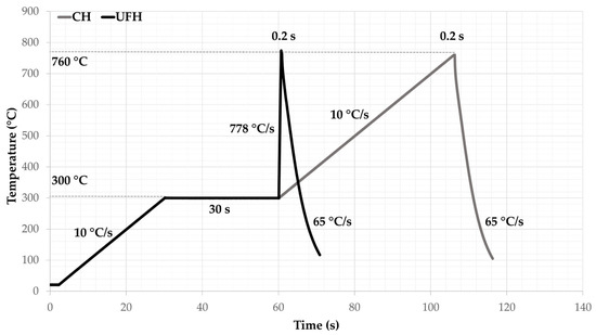
Figure 1.
The parameters of both applied heat treatments. The conventional heat treatment (CH) consisted of a heating with rate of 10 °C/s to the peak temperature followed by quenching, while the heating rate of the ultra-fast heat treatment (UFH) was 780 °C/s. For both treatments, the isothermal soaking time was 0.2 s.
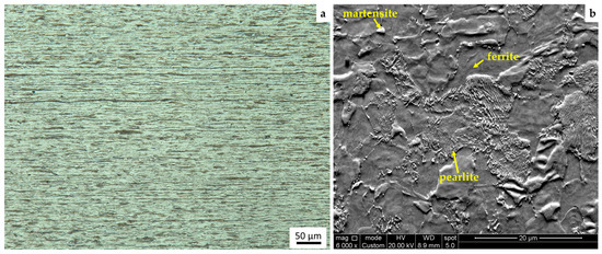
Figure 2.
The initial microstructure of the studied cold-rolled steel consisting of a ferritic matrix with martensite islands and pearlite seen in (a) optical microscopy (OM) and (b) SEM.
The samples for the microstructure characterization were cut from the homogeneously heat-treated zone of the Gleeble specimens. Then they were ground and polished to a mirror-like finish using 6 μm and 1 μm diamond pastes and etched in a chemical solution of 2% v/v HNO3 in ethanol (Nital 2%) for 5–8 s at 20 °C to reveal the microstructure. For transmission electron microscopy (TEM) and transmission Kikuchi diffraction (TKD) analysis, disk samples were cut from the Gleeble specimens. Then they were manually ground to a thickness of 100 μm and ion milled using a precision ion polishing system (PIPS).
For scanning electron microscopy (SEM) analysis, a FEI Quanta TM 450-FEG-SEM (FEI Company, Hillsboro, OR, USA) operating at 20 kV and spot size 5 in SE (BSE) mode was used. The same microscope was used for electron back-scatter diffraction (AMETEK Materials Analysis Division, Mahwah, NJ, USA) analysis operating under the following settings: The accelerating voltage was 20 kV with a beam current corresponding to a spot size of 5, aperture size of 30 μm and working distance of 7 mm. The resulting patterns were acquired on a hexagonal scan grid by a Hikari detector operated with EDAX TSL–OIM-Data Collection version 6 software (AMETEK Materials Analysis Division, Mahwah, NJ, USA). The EBSD scans were performed at a step size of 50 nm. The corresponding orientation data were post-processed with EDAX-TSL-OIM-Data Analysis version 7 software (AMETEK Materials Analysis Division, Mahwah, NJ, USA) using the following grain definition: Misorientation with neighboring grains higher than 5°, minimum number of points per grain was 2 and confidence index (CI) higher than 0.1. The raw EBSD data were post-processed (cleaned) to re-assign the dubiously indexed points using the grain confidence index standardization and neighbor CI correlation procedure. Based on the EBSD data, the prior austenite grains were reconstructed by means of the ARPGE software developed by C. Cayron [29]. The transmission Kikuchi diffraction (TKD) was performed using the same equipment. The working distance was set to 5 mm and the step size to 20 nm. A Jeol JEM-2200FS, 200 kV field emission transmission electron microscope (JEOL Ltd., Tokyo, Japan) was used for the TEM analysis. The continuous cooling transformation (CCT) diagrams were plotted using the models of Kirkaldy [30,31] and Bhadeshia [32] and were calculated taking into account the chemical composition of the steel and the grain size of the parent austenite.
3. Results and Discussion
3.1. Microstructure Comparison
The microstructure of both samples was observed with optical microscopy (OM) and SEM. From OM images (Figure 3a,b), it is seen that both CH and UFH samples consist of martensitic islands and undissolved cementite embedded into ferritic matrix. The pearlitic colonies in the UFH sample (Figure 3b) appear to remain unaffected by the heat treatment and retain their cold-rolled banded morphology from the initial microstructure (Figure 2a). The ferrite grains are more equiaxed in the CH sample, while in the UFH sample they appear to retain the shape of the cold-rolled microstructure. SEM images (Figure 3c,d) show that the microstructure appears more refined in the UFH (as discussed later in this paper) while the disintegration of pearlite is not as pronounced as in the CH sample, since cementite is present in the lamellar and spheroidized forms.

Figure 3.
(a) OM image of the CH sample, (b) OM image of the UFH sample, (c) SEM image of the CH sample, and (d) SEM image of the UFH samples. Both microstructures consist of martensite islands and undissolved pearlitic colonies embedded into a ferritic matrix.
Figure 4 illustrates martensite grains formed at both ferrite/cementite (α/θ) and ferrite/ferrite (α/α) interfaces. This phenomenon takes place in both the CH sample (Figure 4a,b) and the UFH sample (Figure 4c,d). Concerning the phase transformation at the α/α interfaces, it appears that the nucleation of austenite takes place without carbon enrichment, as there is no apparent carbon source (cementite) nearby, and thus the martensite is expected to have very low carbon content. This was studied by Savran [19] who explained thermodynamically that the driving force for this nucleation is the carbon gradient inside a ferritic grain, as carbon is segregated on the grain boundaries. She also showed that during heating in the temperature range temperatures between the Ac1 and Ac3, the maximum carbon content of ferrite is decreasing according to the Fe3C diagram. This rejected carbon also contributes to the local chemical heterogeneity being a driving force for austenite nucleation. As this phenomenon is happening for both slow and ultra-fast heating rates, it can be assumed that it is not affected by the heating rate although the diffusion and segregation of alloying elements depend on it [13,14,15]. The segregation of alloying elements, such as chromium (Cr) and manganese (Mn), on the interfaces of ferrite is studied using energy dispersive X-ray spectrometry (EDXS) in TEM.
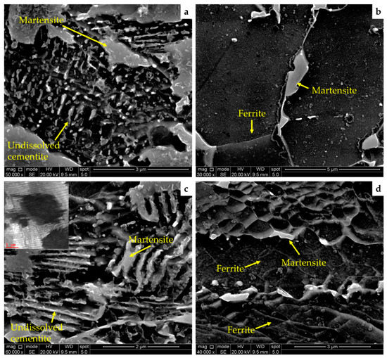
Figure 4.
(a,b) SEM micrographs of the CH sample showing the nucleation of the prior austenite (transformed into martensite during quenching) taking place on both α/α and α/θ interfaces. The same can be seen in the UFH sample in (c,d).
The pearlite was studied under TEM for both samples. Similar to the outcomes of the SEM analysis, undecomposed pearlite is observed in both samples. In the CH sample (Figure 5a), pearlite is found in both lamellar and spheroidized morphologies with the latter prevailing. In the UFH sample (Figure 5b), the lamellar form of pearlite is found in the larger fraction than the spheroidized one. This observation can be rationalized based on shorter heating time during UFH treatment. According to different theories of spheroidization [33], a chemical potential gradient leads to a curvature in the lamellar interface. Atoms move from the curvature of a lamella through diffusion to the flat interfaces of neighboring or the same plates and eventually lead to the break of the lamellar plate. The curvature of the plates can be seen in Figure 5a for the UFH sample. From the EDXS analysis, it is seen that alloying elements such as manganese and chromium are concentrated in the cementite of the microstructure. This is in accordance with the results of Papaefthymiou et al. [9] who predicted the accumulation of these elements in cementite by simulation using Thermo-calc and Dictra software. It is seen from the EDX line scans in Figure 5c,d that the calculated mass % intensity for Cr and Mn was higher in the cementite lamellae and spheres compared to that of the adjacent ferritic matrix. The same was observed for the CH sample in Figure 5f,g. From those figures, it can also be seen that the spheroidization process was more pronounced in the CH samples compared to the UFH sample. Figure 5e, shows that the mass % intensity of Cr and Mn was increasing near the grain boundaries of three ferrite grains. This leads to nucleation of austenite and, after quenching, martensite. Nevertheless, concerning the slow heating, a homogenization of the topical chemical composition takes place due to the longer heating time, as it can be seen from the results of the EDXS analysis (Figure 5h) of the CH sample.
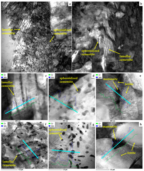
Figure 5.
Bright field scanning transmission electron microscopy (BF-STEM) images of the (a) CH and (b) UFH sample showing undissolved pearlitic colonies. In both samples, the cementite is found in lamellar or spheroidized forms. (c,d) STEM images of spheroidized and lamellar cementite in the UFH sample with EDXS line scans showing higher concentration of Cr and Mn in cementite. (e) STEM image of the UFH sample with EDXS line scan showing the segregation of Cr and Mn on the ferrite grain boundaries. (f,g) The mass % intensity of Cr and Mn in lamellar and spheroidized cementite in the CH sample while (h) shows no segregations of Cr and Mn between martensite and two ferrite grains. The small peaks are due to noise inside the TEM chamber.
3.2. Microstructural Constituents Analysis
EBSD analysis was conducted in order to determine the constituents present in the microstructure. Pearlite (cementite) was not included in the scans as it is not easily recognized by the software. In Figure 6a,b, the image quality (IQ) maps of the CH and UFH samples are shown respectively. It can be clearly seen that the CH treatment leads to larger, equiaxed ferrite grains. Bands from the cold rolling are visible in both maps and in the UFH appear in bigger fraction. In Figure 6c,d, the IQ maps are shown with colored grain average image quality (GAIQ). This means that grains that are less distorted will produce clearer diffraction patterns during the scan, which translate to higher IQ. In this case, these grains are ferritic and appear in red, orange and yellow color. More distorted lattices, which are typical for martensite and recovered ferrite, produce low quality diffraction patterns and thus appear in dark green. Finally, pearlitic colonies produce the lowest quality diffraction patterns and appear as blue in these maps [34,35]. According to these, in Figure 6c it is shown that in the CH sample the large equiaxed ferrite grains have high IQ as they appear in red, orange and yellow, and they cover the largest area of the scan. The lowest IQ colors appear inside the bands of the cold rolling and correspond to martensite, pearlite and recovered ferrite. For the UFH sample in Figure 6d, the case is different. High IQ grains are scarce and the main area of the scan consists of recovered ferrite and pearlite with low IQ. From the IQ alone, it is difficult to distinguish the martensite from the recovered ferrite, so a different approach had to be made. In Figure 6e,f, the grain average image quality map is shown in grayscale with different misorientation angles included. According to [9,13], misorientation angles between 17–47° (black) correspond to ferrite, 48–55° (red) correspond to bainite and 56–65° (blue) correspond to martensite. From the supporting charts in Figure 6g,h, bainitic grains were also expected in the microstructure.
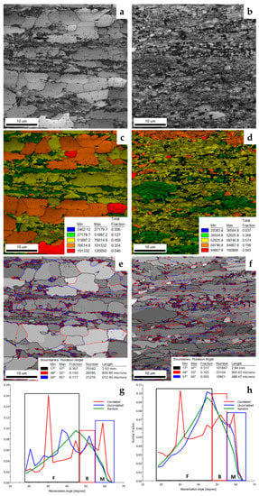
Figure 6.
Grayscale image quality (IQ) map of the CH (a) and UFH (b) sample showing the region of the electron back-scatter diffraction (EBSD) scan. Color-coded grain average image quality (GAIQ) map for the (c) CH and (d) UFH sample. Martensite is indicated in dark green and ferrite in red/orange/yellow colors, gray-scale GAIQ map of the same areas of the CH (e) and UFH (f) with misorientation angles indicating the boundaries between prior austenite grains (PAGs; black), bainite (red) and martensite (blue). The misorientation angle charts for the CH (g) and UFH (h) samples indicate the fraction of each constituent shown in the previous maps.
Austenite was also found in the microstructure of both samples. Figure 7a,b show the phase maps for CH and UFH samples, respectively, which indicate the existence of similar traces of retained austenite in both samples in a very small fraction. Specifically, the amount of retained austenite in the CH sample was 1.1% while in the UFH sample was 0.7%. It is worth mentioning that in both samples the retained austenite is located in the highly deformed pearlitic colonies. In these areas, the local carbon content is higher due to their proximity to the carbon source (cementite). Therefore, the formed austenite was expected to have higher carbon concentration. This leads to a decrease of the local Ms temperature promoting the retainment of austenite in these areas. Due to the chemical composition of the steel, higher fractions of austenite were not expected in the microstructure.
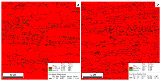
Figure 7.
(a) Phase map of the CH sample, which contained 1.1% austenite, (b) phase map of the UFH sample in which the amount of austenite was 0.7%.
3.3. Texture and Recrystallization Analysis
EBSD analysis was performed to study the effect of UFH treatment on the texture and recrystallization of the steel. In Figure 8, the most important body centered cubic (BCC) texture components in the φ2 = 45° section of Euler space are shown next to the Orientation Distribution Function (ODF) maps of the cold-rolled initial material (IM), the CH sample and the UFH sample. As it appears, the ODF map of the UFH sample is slightly different than that of the initial material (IM). The components of the cold-rolled material have remained unaffected during UFH. On the other hand, the ODF map of the CH appears quite different than those of the IM and the UFH sample. The main reason for this, is the recrystallization of ferrite that takes place on a much larger scale during conventional heating. As it was mentioned by Cerda et al. [26,27,36], during UFH, the recrystallization of ferrite takes place simultaneously (overlaps) with the phase transformation and therefore, the main fraction of ferrite maintains its cold-rolled texture. Main components, such as the (001)[10] and the (001)[0], remain unaffected during UFH as they are frequently present and show a maximum frequency in the texture of both the IM and the UFH sample. The story is similar for components on the ND fiber such as the (554)[225], (111)[11] and (111)[2] that appeared in high frequency in the texture of all three samples. To further analyze this, the grain average misorientation (GAM) map (Figure 9a,b) as well as the kernel average misorientation (KAM) [37] map (Figure 9c,d) were plotted. The former shows the fraction of misorientations inside each grain, while the latter shows the local orientation gradient due to dislocations present in the scanned area. Recrystallized ferrite grains should have low average misorientation and, thus, appear in blue, while the recovered ferrite and martensite appear in green. Local misorientation can be characterized using a misorientation Kernel approach. For a given point, the average misorientation of that point with all of its neighbors is calculated with the provision that misorientations exceeding some tolerance value (maximum misorientation) are excluded from the averaging calculation. Therefore, the KAM map can offer a qualitatively distribution of the strain in the material based on the local misorientations that occur due to strain. During recrystallization, these dislocations mobilize forming new grains and thus the recrystallized ferrite appears free of dislocations. Before the completion of this process, these grains can be located from the dislocations that surround them, before they turn into grain boundaries. This is further explained later in this article under TKD analysis. According to Peranio et al. [38] and Humphreys et al. [39], the most important driving force for recovery and recrystallization is the reduction of strain energy within the ferrite grains, which takes place through a reduction of dislocation density. In addition, the low angle grain boundaries (LAGB) that are expected in recovered ferrite were included in the GAM map with red color in order to further distinguish the two types of ferrite. According to these EBSD maps and from the texture analysis, it was calculated that the recrystallization of ferrite was much more pronounced in the CH sample than in the UFH sample. In specific, it was calculated from the IQ and GAM maps that the area fraction of recrystallized ferrite for the CH sample was 77.4%, while the fraction of recovered ferrite was 8.6%. The remaining fraction (14%) was considered to be martensite and pearlite (cementite). In the case of UFH, the fraction of recrystallized ferrite was calculated as 23.7%, of recovered ferrite as 54.5% and of martensite plus pearlite as 21.8%. From these calculations it is seen that the fraction of martensite in the UFH sample was somewhat higher than that in the CH sample. This result is in contradiction with the previous research [9,13,40,41] where it was supported that the increase of the heating rate leads to an increase in the Ac1 temperature and thus, less martensite is expected in the microstructure of the UFH sample than in the CH sample. Though, the difference can be explained by the lack of recrystallization of ferrite in the UFH sample. According to [36], the phase transformation in deformed ferrite is faster than in recrystallized ferrite as it provides an increased number of nucleation sites for austenite formation. The deformation also reduced the nucleation energy barrier between α/γ interfaces by increasing the strain energy. This strain energy is the driving force for both recrystallization and phase transformation [42,43]. Finally, the deformed ferrite contains a larger number of dislocations and grain boundaries. These lead to a dislocation pipe diffusion of carbon, which favors thermodynamically the phase transformation of austenite [44]. Cerda [45] and Meshkov [46] related this phenomenon to the spheroidization of cementite that takes place in CH. Thus, the higher fraction of martensite in the microstructure of the UFH sample can be explained even though the transformation temperatures have shifted to higher levels than those expected in equilibrium conditions.
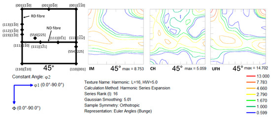
Figure 8.
Positions of the most important BCC texture components in the φ2 = 45° section of Euler space are shown followed by the ODF maps for the cold-rolled initial material (IM), the CH and the UFH samples. For the UFH, the cold-rolled texture of the IM is maintained due to insufficient time for recrystallization of ferrite.
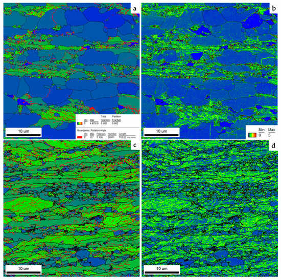
Figure 9.
The grain average misorientation (GAM) map for the (a) CH and (c) the UFH sample including the low angle grain boundaries (LAGBs; 5–15°, red lines). Recrystallization of ferrite is expected to result in lower grain average misorientations and appear in blue with no LAGBs. Recovered ferrite and martensite appear in green and LAGBs are included in the grains. Supplementary kernel average misorientation (KAM) maps for the (b) CH and (d) UFH show the local misorientation due to dislocations present in the lattice. Recrystallized ferrite appears with much lower dislocation density than recovered ferrite and martensite.
Further analysis of the recovery and recrystallization of ferrite was performed using the TKD method. From the maps in Figure 10, it appears that during the heating of the CH, the dislocations move and start to accumulate forming Low Angle Grain Boundaries (LAGBs) shown in white lines. With increased heating time (i.e., slower heating rate), the recovery and recrystallization phenomena can take place and these boundaries are expected to become High Angle Grain Boundaries (HAGBs) (black lines) in order to form new grains with lower strain internal energy and free of dislocations (Figure 10b,c). From the Inverse Pole Figure (IPF) map of Figure 10c, it appears that these dislocation ‘walls’ are responsible for orientation gradients within a single grain. The case is not the same for the UFH sample. In these maps martensite was removed as it reached an image quality lower than 0.1 and appears as black areas in Figure 10d–f. In this case, the dislocation density was high in the ferritic grains neighboring to martensite grains. This is expected due to the difference of the hardness between martensite and ferrite [37]. The ‘walls’ that appear in the CH sample were also not observed in the UFH sample. This means that, after heating with very high rates, the dislocations were not affected indicating that recovery and recrystallization of ferrite was impeded.
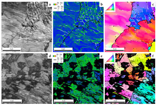
Figure 10.
(a) IQ map of the CH sample obtained by transmission Kikuchi diffraction (TKD). (b) KAM map of the same area showing the result of dislocations and their density and the LAGBs (white) and HAGBs (black). (c) IPF map of the same area showing the misorientations within the ferrite grains caused by the dislocations. LAGBs and HAGBs appear in the same colors. The same maps are shown for the UFH sample in (d–f).
3.4. Grain Size Analysis
EBSD was used for the grain size analysis. Three scans for each condition (CH and UFH) were obtained with a scan size of 40 μm × 40 μm. For the CH treatment, the scans included an average of 7059 grains while the scans for the UFH treatment included an average of 9818 grains. The ARPGE 2.4 software, developed by C. Cayron [29] in École Polytechnique Fédérale de Lausanne—Laboratoire de Métallurgie ThermoMécanique (EPFL-LMTM), was used in automatic mode to plot the grain boundary (GB) maps of the reconstructed prior austenite grains (PAGs) for both samples and are shown in Figure 11a,d. The average number of grains analyzed by the software was 43 for the CH and 55 for the UFH. For the UFH (Figure 11d), these PAGs combined with the proeutuctoid ferrite have significantly smaller size than the CH sample. In particular, the average calculated grain area for the PAGs was 71.87 μm2 for the CH and 64.43 μm2 for the UFH. After quenching, the final microstructure had a grain average area of 17.27 μm2 for the CH and 12.61 μm2 for the UFH. The reason for these smaller austenite grains is most likely that austenite nucleates at the interface of undissolved carbides with ferrite and at ferrite/ferrite interfaces, therefore smaller PAGs lead to finer microstructure [9]. Moreover, undissolved pearlite–spheroidized cementite has a pinning effect, thus, impeding further the growth of austenite grains by impeding the movement of austenite interfaces [38,39]. This effect can be seen in Figure 12a for the CH sample and Figure 12b for the UFH sample. In the former, the disintegration and spheroidization of pearlite is visible with very fine ferrite grains in between, while in the latter, the dissolution of pearlite is even less pronounced and cementite partly maintains its lamellar form. After quenching, the microstructural constituents mostly had an average grain area of 17.3 μm2 for the CH and 12.6 μm2 for the UFH sample.
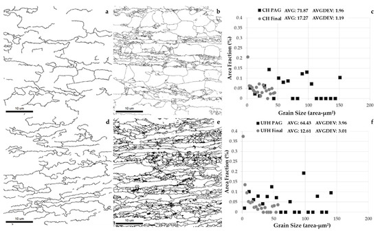
Figure 11.
(a) Grain boundary (GB) map of the reconstructed PAGs of the CH sample with the use of the ARPGE [29] software, (b) GB map of the reconstructed PAGs of the UFH sample with the use of the ARPGE [29] software, (c) grain size chart for the PAGs of both samples indicating the refinement of austenite in UFH sample, (d) GB map of the final microstructure of the CH sample, (e) GB map of the final microstructure of the UFH sample, and (f) grain size chart for the final microstructure of both samples indicating the refinement of grains and laths in the UFH sample.
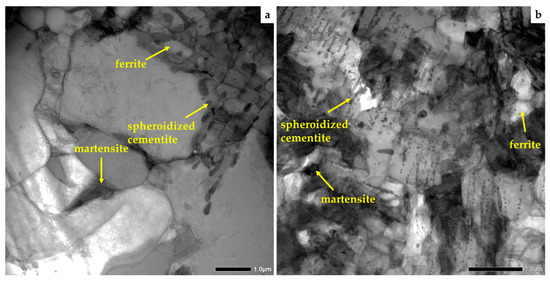
Figure 12.
(a) Undissolved spheroidized cementite in the microstructure of the CH sample is leading to grain refinement, as it impedes the movement of GBs during heating. (b) The same case for the UFH sample with the only difference that cementite maintains its lamellar morphology to a greater extent.
According to the sizes of the PAGs calculated from EBSD, the CCT diagrams were plotted using the models of Kirkaldy [30,31] and Bhadeshia [32]. From these diagrams, the transformation starting temperatures for bainite (Bs) can be seen in Figure 13. During the calculation, the chemical composition was assumed homogeneous and the grain size varied between 1 and 8 μm. The grain size was selected based on the average grain sizes that were calculated from the EBSD. The calculations were also made assuming equilibrium conditions. From this diagram it can be concluded that as the grain size of the parent austenite was decreasing, the curve showing the position of the Bs shifted to the left (i.e., decreasing the incubation time), thus enabling formation of bainite during quenching with rates between 10 and 100 °C/s. This supports the aforementioned presence of bainite in the microstructure, as was indicated in the EBSD analysis. According to this model, the Ms temperature for the given chemical composition was 310 °C. Papaefthymiou et al. [9] have shown that during UFH treatment, heterogeneity is expected not only in the grain size but also in the chemical composition. However, calculations were based on the assumption of the homogeneous grain structure, homogeneous chemical compositions and equilibrium conditions. Therefore, the theoretical results were expected to differ from the experimental ones, as microstructure formed during UFH treatment was characterized by an inhomogeneous grain size and chemical gradients.
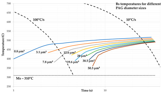
Figure 13.
The bainite (Bs) temperature calculated in the continuous cooling transformation (CCT) diagrams [30,31,32] for variating PAG sizes for the studied chemical composition. For a cooling rate of 65 °C/s, formation of bainite is expected for grains having a size between 1–8 μm.
4. Conclusions
In this article, the effect of ultra-fast heating on the microstructure of Dual Phase steels was studied. To evaluate this, the microstructure of the ultra-fast heated sample was compared with the microstructure of a conventionally heated sample.
It is shown that very short heating time during ultrafast heating significantly impeded the decomposition of pearlite of the initial microstructure. Instead, spheroidization of the cementite in pearlite took place during both heat treatments. This process was more pronounced in the conventional heat treatment because of the longer heating time. The undissolved cementite led to microstructure refinement by suppressing the movement of grain boundaries and thus, the growth of austenite. This grain refinement was more pronounced in the ultra-fast heated sample because of the lack of time for austenite grain growth and because of the less advanced disintegration of pearlite. Therefore, the microstructure consists of ferrite, martensite, undissolved cementite, while traces of retained austenite were also found inside the partially disintegrated pearlitic colonies. The cementite in these colonies appeared in both lamellar and spheroidized structures. It also contributed to the refinement of the microstructure and favored the retainment of austenite by the increase of the local carbon content. Indications for the presence of bainite in the microstructure were also found. The grain refinement enables the formation of bainite in the microstructure during quenching according to model calculations and EBSD analysis. The inhomogeneity of the chemical composition was another reason for the formation of bainite. Alloying elements such as Mn and Cr were found in the undissolved cementite after both heat treatments. High concentrations of these elements were also found in martensite laths for the ultra-fast treated sample, while in the conventionally treated sample, homogenization of the chemical composition was achieved.
The lack of heating time also retarded the recrystallization of ferrite, which took place simultaneously with the α → γ phase transformation thus maintaining the cold-rolled texture of the initial material. Rearrangement of the dislocations and their partial annihilation (i.e., recovery) was achieved during conventional treatment resulting in the formation of low angle grain boundaries before recrystallization. This was not observed during ultra-fast heat treatment. The recrystallization of ferrite was partially impeded during rapid heating. This led to two types of ferrite in the microstructure of the steel, recrystallized and non-recrystallized. These types of ferrite and the presence of dislocations in the microstructure affected the local Ac1 temperature favoring the nucleation of austenite grains. The increased number of austenite nuclei and the impeding of their growth due to the short heating times plus the pinning from the undissolved cementite is another reason for the microstructure refinement. Therefore, ultra-fast heating can be used as an alternative method to produce ultra-fine grained dual phase steels.
Further studies are imperative and in order for this grade with the scope to determine the dependence of its mechanical properties on the refined mixed microstructure and the chemical composition of its constituents. This research is the stepping stone for the production of commercial DP grades minimizing their treatment time while maintaining the desired strength/ductility ratio.
Author Contributions
Conceptualization, R.H.P. and S.P.; Data curation, A.B. and E.H.D.; Formal analysis, A.B.; Investigation, A.B., E.H.D., V.B. and I.S.; Methodology, A.B.; Project administration, R.H.P. and S.P.; Resources, R.H.P. and S.P.; Software, A.B., E.H.D. and I.S.; Supervision, R.H.P. and S.P.; Validation, A.B. and I.S.; Visualization, A.B. and V.B.; Writing—original draft, A.B.; Writing—review & editing, R.H.P. and S.P.
Funding
Ilchat Sabirov acknowledges gratefully funding from Madrid region under programme S2018/NMT-4381-MAT4.0-CM project. Student Eliseo Hernandez Duran acknowledges the support of CONICYT PFCHA/Doctorado Nacional/2017-21171319.
Acknowledgments
The authors express their gratitude to the students Florian Vercruysse and Ksenija Nikolic for their assistance on the use of the equipment that was employed during this research.
Conflicts of Interest
The authors declare no conflict of interest.
References
- Gaspar, M.; Balogh, A. GMAW experiments for advanced (Q+T) high strength steels. Prod. Prof. Syst. 2013, 6, 9–24. [Google Scholar]
- Samei, J.; Zhou, L.; Kang, J.; Wilkinson, D.S. Microstructural analysis of ductility and fracture in fine-grained and ultrafine-grained vanadium-added DP1300 steels. Int. J. Plast. 2019, 117, 58–70. [Google Scholar] [CrossRef]
- Zaefferer, S.; Ohlert, J.; Bleck, W. A study of microstructure, transformation mechanisms and correlation between microstructure and mechanical properties of a low alloyed TRIP steel. Acta Mater. 2004, 52, 2765–2778. [Google Scholar] [CrossRef]
- Speer, J.; Matlock, D.; De Cooman, B.; Schroth, J. Carbon partitioning into austenite after martensite transformation. Acta Mater. 2003, 51, 2611–2622. [Google Scholar] [CrossRef]
- Cola, G. Properties of bainite nucleated by water quenching in 80 ms. In Proceedings of the 1st International Symposium on Steel Science, Kyoto, Japan, 16–19 May 2007; Furuhara, T., Tsuzaki, K., Eds.; Iron and Steel Institute of Japan: Tokyo, Japan, 2007; pp. 187–190. [Google Scholar]
- Lolla, S.V.T. Understanding Microstructure Evolution in Rapid Thermal Processing of AISI 8620 Steel. Master’s Thesis, The Ohio State University, Columbus, OH, USA, 2009. [Google Scholar]
- Lolla, S.V.T.; Alexandrov, B.; Babu, S.; Cola, G. Towards Understanding the Microstructure Development during Heating and Cooling of Steels. In Proceedings of the International Conference on Processing and Manufacturing of Advanced Materials-THERMEC’2009, Berlin, Germany, 25–29 August 2009. [Google Scholar]
- Lolla, T.; Cola, G.; Narayanan, B.; Alexandrov, B.; Babu, S.S. Development of rapid heating and cooling (flash processing) process to produce advanced high strength steel microstructures. Mater. Sci. Technol. 2011, 27, 863–875. [Google Scholar] [CrossRef]
- Papaefthymiou, S.; Banis, A.; Bouzouni, M.; Petrov, R.H. Effect of Ultra-Fast Heat Treatment on the Subsequent Formation of Mixed Martensitic/Bainitic Microstructure with Carbides in a CrMo Medium Carbon Steel. Metals 2019, 9, 312. [Google Scholar] [CrossRef]
- Lan, L.; Chang, Z.; Fan, P. Exploring the Difference in Bainite Transformation with Varying the Prior Austenite Grain Size in Low Carbon Steel. Metals 2018, 8, 988. [Google Scholar] [CrossRef]
- Banis, A.; Papaefthymiou, S. Microstructure Characterization of an Ultra-Fast Heated Medium Carbon Chromium-Manganese High Strength Steel. Int. J. Met. Met. Phys. 2018, 3, 1–14. [Google Scholar] [CrossRef]
- Cerda, F.C.; Schulz, B.; Celentano, D.; Monsalve, A.; Sabirov, I.; Petrov, R. Exploring the microstructure and tensile properties of cold-rolled low and medium carbon steels after ultrafast heating and quenching. Mater. Sci. Eng. A 2019, 745, 509–516. [Google Scholar] [CrossRef]
- Papaefthymiou, S.; Bouzouni, M.; Petrov, R.H. Study of Carbide Dissolution and Austenite Formation during Ultra–Fast Heating in Medium Carbon Chromium Molybdenum Steel. Metals 2018, 8, 646. [Google Scholar] [CrossRef]
- Bouzouni, M. Modeling of the Steel Microstructure Gained after the Application of an Ultra-Fast Heat Treatment. J. Nanosci. Adv. Technol. 2017, 2, 15–19. [Google Scholar] [CrossRef]
- Bouzouni, M.; Papaefthymiou, S. Preliminary Study of Carbide Dissolution during an Ultra-Fast Heat Treatment in Chromium Molybdenum Steel. Int. J. Met. Met. Phys. 2017, 2, 1–7. [Google Scholar] [CrossRef]
- Kaluba, W.; Taillard, R.; Foct, J. The bainitic mechanism of austenite formation during rapid heating. Acta Mater. 1998, 46, 5917–5927. [Google Scholar] [CrossRef]
- Kaluba, W.; Taillard, R.; Foct, J. A reply to “discussion to “the bainitic mechanism of austenite formation during rapid heating. Scr. Mater. 2000, 42, 511–516. [Google Scholar] [CrossRef]
- Aaronson, H.; Nie, J. Discussion to “the bainitic mechanism of austenite formation during rapid heating”. Scr. Mater. 2000, 42, 505–509. [Google Scholar] [CrossRef]
- Savran, V.I. Austenite Formation in C-Mn Steel. Ph.D. Thesis, TU Delft, Delft, The Netherlands, 2009. [Google Scholar]
- Castro Cerda, F.M. Third Generation Advanced High Strength Steels via Ultrafast Heating. Ph.D. Thesis, Ghent University, Ghent, Belgium, 2017. [Google Scholar]
- Speich, G.; Szirmae, A.; Richards, M. Formation of austenite from ferrite and ferrite-carbide aggregates. Trans. TMS-AIME 1969, 245, 1063–1074. [Google Scholar]
- Judd, R.R.; Paxton, H.W. Kinetics of Austenite Formation from a Spheroidized Ferrite-Carbide Aggregates. Trans. TMS-AIME 1968, 242, 206–215. [Google Scholar]
- Liu, Z.-K.; Ågren, J. Morphology of cementite decomposition in an fe-cr-c alloy. Met. Mater. Trans. A 1991, 22, 1753–1759. [Google Scholar] [CrossRef]
- Liu, Z.-K.; Höglund, L.; Jonsson, B.; Ågren, J. An experimental and theoretical study of cementite dissolution in an Fe-Cr-C alloy. Met. Mater. Trans. A 1991, 22, 1745–1752. [Google Scholar] [CrossRef]
- Gouné, M.; Maugis, P.; Drillet, J. A Criterion for the Change from Fast to Slow Regime of Cementite Dissolution in Fe–C–Mn Steels. J. Mater. Sci. Technol. 2012, 28, 728–736. [Google Scholar] [CrossRef]
- Cerda, F.M.C.; Kestens, L.A.I.; Monsalve, A.; Petrov, R.H.; Cerda, F.C. The Effect of Ultrafast Heating in Cold-Rolled Low Carbon Steel: Recrystallization and Texture Evolution. Metals 2016, 6, 288. [Google Scholar] [CrossRef]
- Cerda, F.M.C.; Kestens, L.A.I.; Petrov, R.H. “Flash” Annealing in a Cold-Rolled Low Carbon Steel Alloyed with Cr, Mn, Mo, and Nb: Part II-Anisothermal Recrystallization and Transformation Textures. Steel Res. Int. 2018, 90, 1–13. [Google Scholar]
- Landheer, H. Nucleation of Ferrite in Austenite: The Role of Crystallography. Ph.D. Thesis, TU Delft, Delft, The Netherlands, 2010. [Google Scholar]
- Cayron, C. ARPGE: A computer program to automatically reconstruct the parent grains from electron backscatter diffraction data. J. Appl. Crystallogr. 2007, 40, 1183–1188. [Google Scholar] [CrossRef] [PubMed]
- Kirkaldy, J.S.; Venugopolan, D. Phase Transformations in Ferrous Alloys; Marder, A.R., Goldstein, J.I., Eds.; AIME: Warrendale, PA, USA, 1984; p. 125. [Google Scholar]
- Kirkaldy, J.S.; Thomson, B.A.; Baganis, E.A. Hardenability Concepts with Applications to Steel; Kirkaldy, J.S., Doane, D.V., Eds.; AIME: Warrendale, PA, USA, 1978; p. 82. [Google Scholar]
- Bhadeshia, H.K.D.H. The Driving Force for Martensitic Transformation in Steels. Met. Sci. 1981, 15, 175–177. [Google Scholar] [CrossRef]
- Tian, Y.L.; Kraft, R.W. Mechanisms of Pearlite Spheroidization. Met. Mater. Trans. A 1987, 18, 1403–1414. [Google Scholar] [CrossRef]
- Petrov, R.; Kestens, L.; Wasilkowska, A.; Houbaert, Y. Microstructure and texture of a lightly deformed TRIP-assisted steel characterized by means of the EBSD technique. Mater. Sci. Eng. A 2007, 447, 285–297. [Google Scholar] [CrossRef]
- Pinard, P.T.; Schwedt, A.; Ramazani, A.; Prahl, U.; Richter, S. Characterization of Dual-Phase Steel Microstructure by Combined Submicrometer EBSD and EPMA Carbon Measurements. Microsc. Microanal. 2013, 19, 996–1006. [Google Scholar] [CrossRef] [PubMed]
- Cerda, F.M.C.; Goulas, C.; Sabirov, I.; Papaefthymiou, S.; Monsalve, A.; Petrov, R. Microstructure, texture and mechanical properties in a low carbon steel after ultrafast heating. Mater. Sci. Eng. A 2016, 672, 108–120. [Google Scholar] [CrossRef]
- Calcagnotto, M.; Ponge, D.; Raabe, D. On the Effect of Manganese on Grain Size Stability and Hardenability in Ultra-Fine-Grained Ferrite-Martensite DualPhase Steels. Metall. Mater. Trans. A 2012, 43, 37–42. [Google Scholar] [CrossRef]
- Peranio, N.; Li, Y.; Roters, F.; Raabe, D. Microstructure and texture evolution in dual-phase steels: Competition between recovery, recrystallization, and phase transformation. Mater. Sci. Eng. A 2010, 527, 4161–4168. [Google Scholar] [CrossRef]
- Humphreys, F.J.; Hatherly, M. Recrystallization and Related Annealing Phenomena; Elsevier: Oxford, UK, 2004. [Google Scholar]
- Valdes-Tabernero, M.A.; Vercruysse, F.; Sabirov, I.; Petrov, R.H.; Monclús, M.A.; Molina-Aldareguía, J.M. Effect of Ultrafast Heating on the Properties of the Microconstituents in a Low-Carbon Steel. Met. Mater. Trans. A 2018, 49, 3145–3150. [Google Scholar] [CrossRef]
- De Knijf, D.; Puype, A.; Föjer, C.; Petrov, R. The influence of ultra-fast annealing prior to quenching and partitioning on the microstructure and mechanical properties. Mater. Sci. Eng. A 2015, 627, 182–190. [Google Scholar] [CrossRef]
- Oliveira, M.A.F.; Jorge, A.M., Jr.; Balancin, O. Influence of strain-induced nucleation on the kinetics of phase transformation in a forging steel during warm working. Scr. Mater. 2004, 50, 1157. [Google Scholar] [CrossRef]
- Porter, D.A.; Easterling, K.E. Phase Transformations in Metals and Alloys; Van Nostrand Reinhold: Wokingham, UK, 1981. [Google Scholar]
- Love, G.R. Dislocation Pipe Diffusion. Acta Metall. 1964, 12, 731–737. [Google Scholar] [CrossRef]
- Cerda, F.C.; Goulas, C.; Sabirov, I.; Kestens, L.; Petrov, R. The effect of the pre-heating stage on the microstructure and texture of a cold rolled FeCMnAlSi steel under conventional and ultrafast heating. Mater. Charact. 2017, 130, 188–197. [Google Scholar] [CrossRef]
- Meshkov, Y.Y.; Pereloma, E.V. 17—The effect of heating rate on reverse transformations in steels and Fe-Ni-based alloys. In Phase Transformations in Steels; Pereloma, E., Edmonds, D.V., Eds.; Woodhead Publishing: Cambridge, UK, 2012; pp. 581–618. [Google Scholar]


© 2019 by the authors. Licensee MDPI, Basel, Switzerland. This article is an open access article distributed under the terms and conditions of the Creative Commons Attribution (CC BY) license (http://creativecommons.org/licenses/by/4.0/).