Article

Microstructure and Mechanical Properties of Resistance Heat-Assisted High-Power Ultrasonic Dissimilar Welded Cu/Al Joint

1
School of Mechanical Engineering, Yangtze University, Jingzhou 434023, China
2
School of Mechanical and Automotive Engineering, South China University of Technology, Guangzhou 510640, China
*
Author to whom correspondence should be addressed.
Metals 2019, 9(8), 873; https://doi.org/10.3390/met9080873
Submission received: 9 July 2019 / Revised: 7 August 2019 / Accepted: 7 August 2019 / Published: 8 August 2019
(This article belongs to the Special Issue Advanced Welding Technology in Metals)

Abstract

:
The Cu/Al dissimilar joint, welded by high-power ultrasonic welding technology, is still facing challenges despite the significant research attention it has attracted. In this work, the microstructure and mechanical properties of resistance heat-assisted high-power ultrasonic welding of Cu/Al are investigated, in order to obtain high-quality joints. The intermetallic compound (IMC) at the interface of hybrid welding is primarily composed of Al2Cu, and the additional resistance of heat reduces the thickness of this brittle IMC layer. The average shear stress for the joint prepared by hybrid welding is ~97 MPa, which is higher compared to the joint strength without resistance heat (90 MPa). Moreover, the duration of the hybrid welding process is shorter. Finally, the fracture of the hybrid weld is found to be a brittle–ductile hybrid mode.

1. Introduction

Ultrasonic welding can produce welds faster and with less material loss than other common welding methods of dissimilar lap joints, such as laser welding (LW) [1,2] and friction stir welding (FSW) [3,4]. It also requires lower energy input than resistance spot welding (RSW) [5]. These advantages make this method suitable for welding dissimilar metals, such as copper and aluminum, which have high thermal and electrical conductivity and are widely used in the aerospace industry and battery packs [6,7]. Recently, the dissimilar copper and aluminum joint, welded by high-power ultrasonic welding (HPUSW) technique, is becoming more attractive due to its ability to join thicker sheets [8]. However, a major challenge of this technique is the thick continuous intermetallic compound (IMC) layer that is formed at the Cu/Al interface, which reduces the mechanical properties of the joint and leads to poor welding quality [9,10]. This issue inhibits the wider commercialization of this technique. Recently, interlayer metals, such as Al and Zn, were placed on the Cu/Al interface and were used to enhance the ultrasonic welding quality of the joint [11,12]. However, the metallurgical reaction at the specimen/interlayer interface is very complicated, making it difficult to understand the effects of the interlayer on the mechanical properties of the joints [13]. In addition, during the ultrasonic metal welding process, the metal interlayer will widen the heat-affected zone [14].
In order to improve the joint quality, several types of energy sources have been used to assist the ultrasonic welding, such as laser beam and resistance heat. Dehelean et al. [15] carried out hybrid ultrasonic-resistance welding of advanced materials and found that the resistance heat results in low weld strength. In our previous work, resistance heat-assisted low-power ultrasonic welding was proposed and it was found that the additional resistance heat can significantly increase the peak power of ultrasonic vibration and the welding strength [16]. Unfortunately, this welding method is only suitable for joining thin sheets. The finite element method was used to study the influence of additional resistance heat on the interface temperature and plastic deformation of the material, during ultrasonic welding [17]. However, the mechanical properties and microstructure of joints prepared by resistance heat-assisted high-power ultrasonic welding (RUSW) have not yet been reported. In this paper, the mechanical properties and microstructure of Cu/Al joints prepared by RUSW are studied, in order to obtain high welding quality.

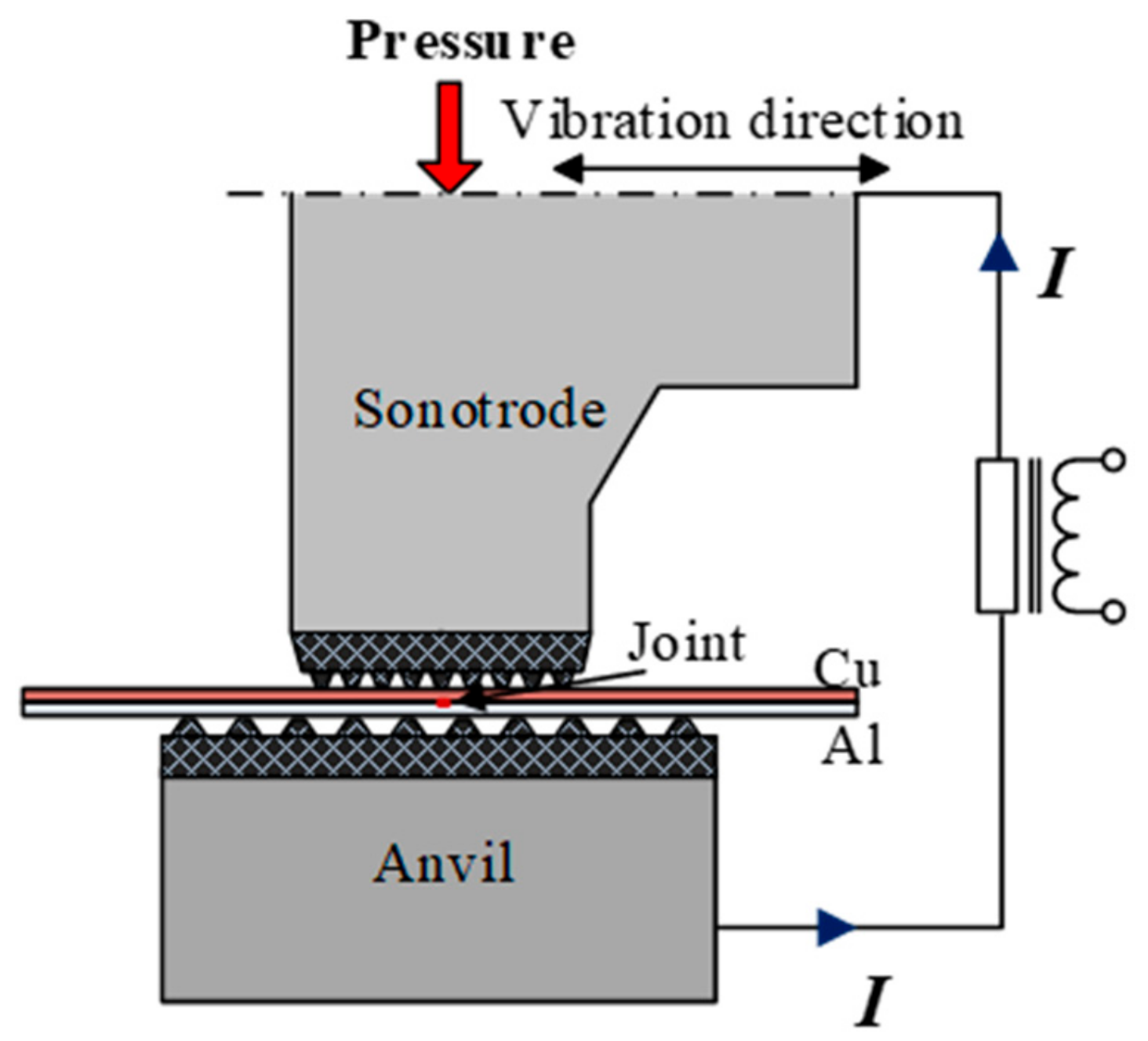
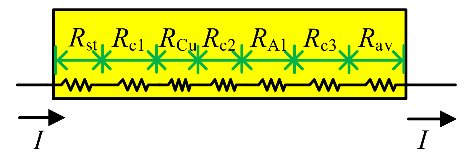
2. The Principle of Hybrid Welding

The RUSW system includes a lateral-driven high-power ultrasonic welder and an inverter resistance power supply. The current and ultrasound vibrations act on the workpiece simultaneously. In RUSW, a high pressure creates sufficient contact between the upper and lower workpieces to ensure electrical conductivity between them. The ultrasonic waves from the sonotrode pass through the upper workpiece, causing local relative vibration at the upper/lower specimen interface and thus generating friction. Resistance, friction, and plastic deformation heat cause the interface temperature to rise rapidly, resulting in solid-state joining. Figure 1 shows the schematic diagram of the RUSW process.
In RUSW, the generated heat QRUSW includes one part from ultrasonic vibration QUSW and another part from electrical resistance QRSW, as described below:
Q RUSW = Q USW + Q RSW   .
Ultrasonic vibration energy QUSW, is converted into friction heat Qf and plastic deformation heat Qq [18], as shown in Equation (2):
Q USW = Q f + Q q .
QRSW can be expressed as:
Q RSW = I 2 × R total × t
where I is the electrical current and t is the welding time. R is the total resistance providing thermal input during the RUSW process. Total resistance R involves seven components, as shown in Figure 2, and can be expressed as:
R total = R st + R c 1 + R cu + R c 2 + R Al + R c 3 + R a v
where Rst is the resistance of the sonotrode, RCu is the resistance of Cu plate, RAl is the resistance of Al plate, Rav is the resistance of the anvil, Rc1 is the contact resistance between the sonotrode and the upper specimen, Rc2 is the contact resistance between the upper and the lower specimen, and Rc3 is the contact resistance between the anvil and the lower specimen.
In RUSW, material softening arises from two sources: Ultrasonic softening and thermal softening [19]. Thus, the material softening rate in the welding process can be expressed as [18]:
α = α us × α T = α us × σ T σ T 0
where, αus and αT are the ultrasonic softening rate and thermal softening rate, respectively. σT and σT0 are the yield stresses of material at temperature T and room temperature, respectively.
According to the above theory, the interaction between the ultrasonic vibration and the electrical resistance can be described as follows: When the ultrasonic vibration is applied to the RSW, the intensity of the material softening is increased, according to Equation (5). This benefits the breaking of the metal oxide film and promotes the resistance heat. When the resistance heat acts on the ultrasonic metal welding, it promotes the increase in interface temperature according to Equation (1), and thus promotes the metallurgical reaction on the interface. These interactions may potentially increase the weld strength of Cu/Al joints.

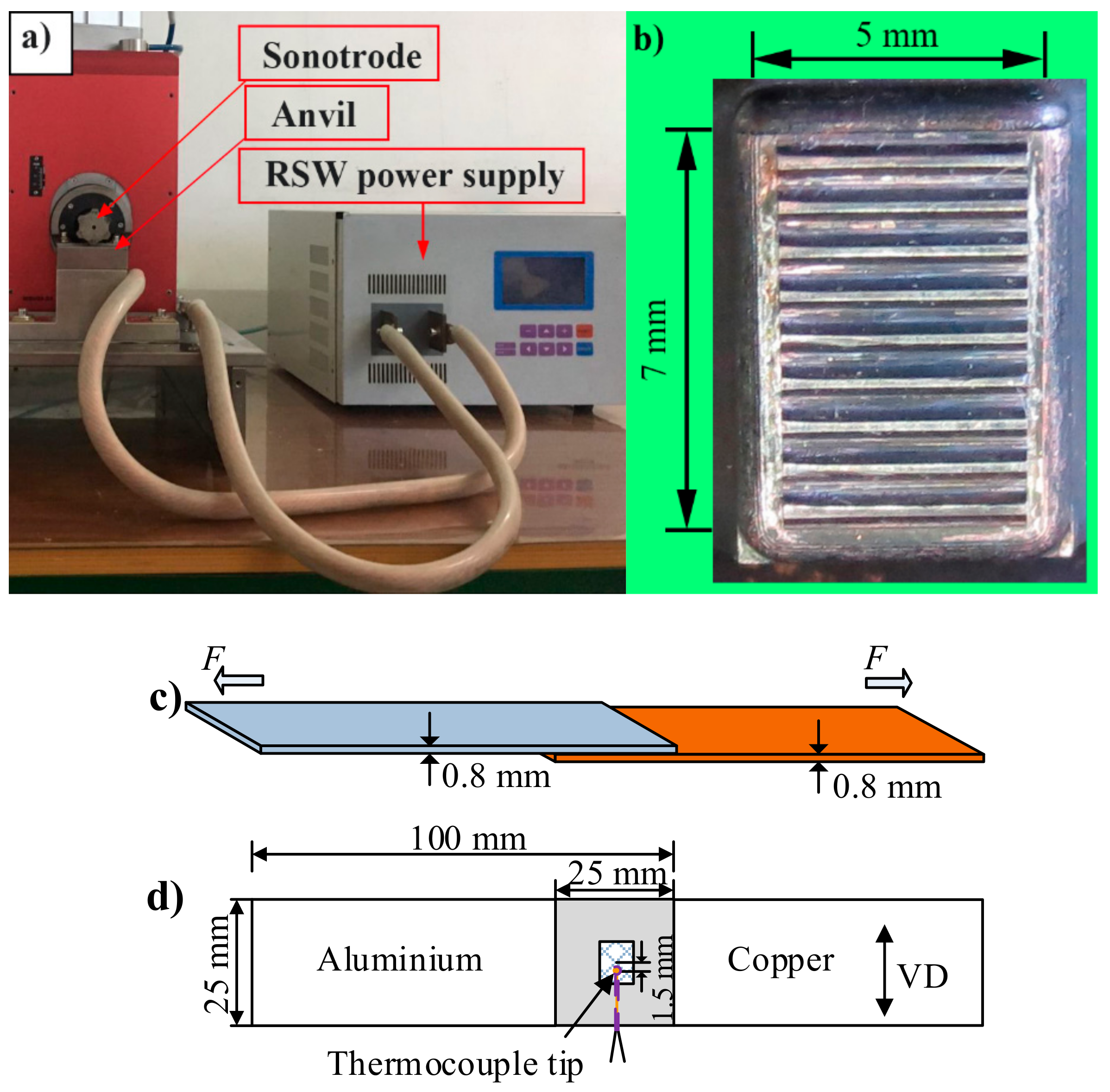
3. Experimental Details

The RUSW system included a lateral-driven, high-power ultrasonic welder (4.0 kW) and an inverter resistance power supply (Figure 3a). The high-power ultrasonic welder used a lateral spot welder (Telsonic M5000) with a vibration frequency of 20 kHz. A rectangular sonotrode tip with dimensions of 7 mm × 5 mm was used in this study (Figure 3b). To avoid the occurrence of arcs and marks on the Cu/Al interface, the shape of the sonotrode tooth was trapezoidal, instead of triangular. A resistance spot welder with a maximum electrical current supply of 4000 A was used. A zero-to-peak amplitude of 24 μm, current of 3900 A, clamping force of 1975 N and welding time of 0.2 s were selected for the hybrid welding. The interval between each sonotrode tooth was 0.9 mm. In order to avoid high current density occurring at the anvil/Al interface, the interval of the anvil tooth was 0.1 mm larger than that of the sonotrode tooth. For the conventional HPUSW, the welding time was 0.5 s while the clamping force was set to 1575–1975 N. The specimens were 6061-T6 aluminum alloy and pure copper, cut into 100 × 25 × 0.8 mm3 pieces. The overlapping area of the specimens was 25 × 25 mm2. In this work, prior to welding, the samples were ultrasonically cleaned with acetone to remove surface contaminants. The ultrasonic vibration direction (VD) was perpendicular to the length direction of the workpiece (Figure 3d).
The fracture surface morphology was observed by a JEOL JSM-7001F field emission gun scanning electron microscope (FEG SEM) (Jeol, Tokyo, Japan), equipped with an energy-dispersive X-ray spectrometer (EDS). X-ray diffraction (XRD) analysis was carried out using a PANalytical Empyrean (Malvern PANalytical, Almelo, The Netherlands) diffractometer to identify the phases of IMC at the welding interface. The XRD spectra were measured from 20° to 90°, with a step size of 0.02° and a scanning speed of 0.02 °/s. The tensile tests were performed using a Shimadzu AGS-X electronic testing machine (SHIMADZU, Kyoto, Japan). Tensile-shear tests were carried out at a tensile speed of 1 mm/min. At least three samples were tested for each process condition. The mechanical strength of the joints was evaluated according to tensile-shear strength, which was calculated by dividing the maximum tensile-shear force by the sonotrode area of 7 mm × 5 mm.
The temperature was measured using 0.1 mm K-type thermocouples, inserted through a semi-circular groove of radius 0.5 mm on the aluminum sheet surface. Thermocouple tip was placed at 1.5 mm from the center of the Cu/Al interface. Figure 3c,d show a schematic of the tensile-shear and thermocouple temperature measurement tests, respectively.

4. Results and Discussion

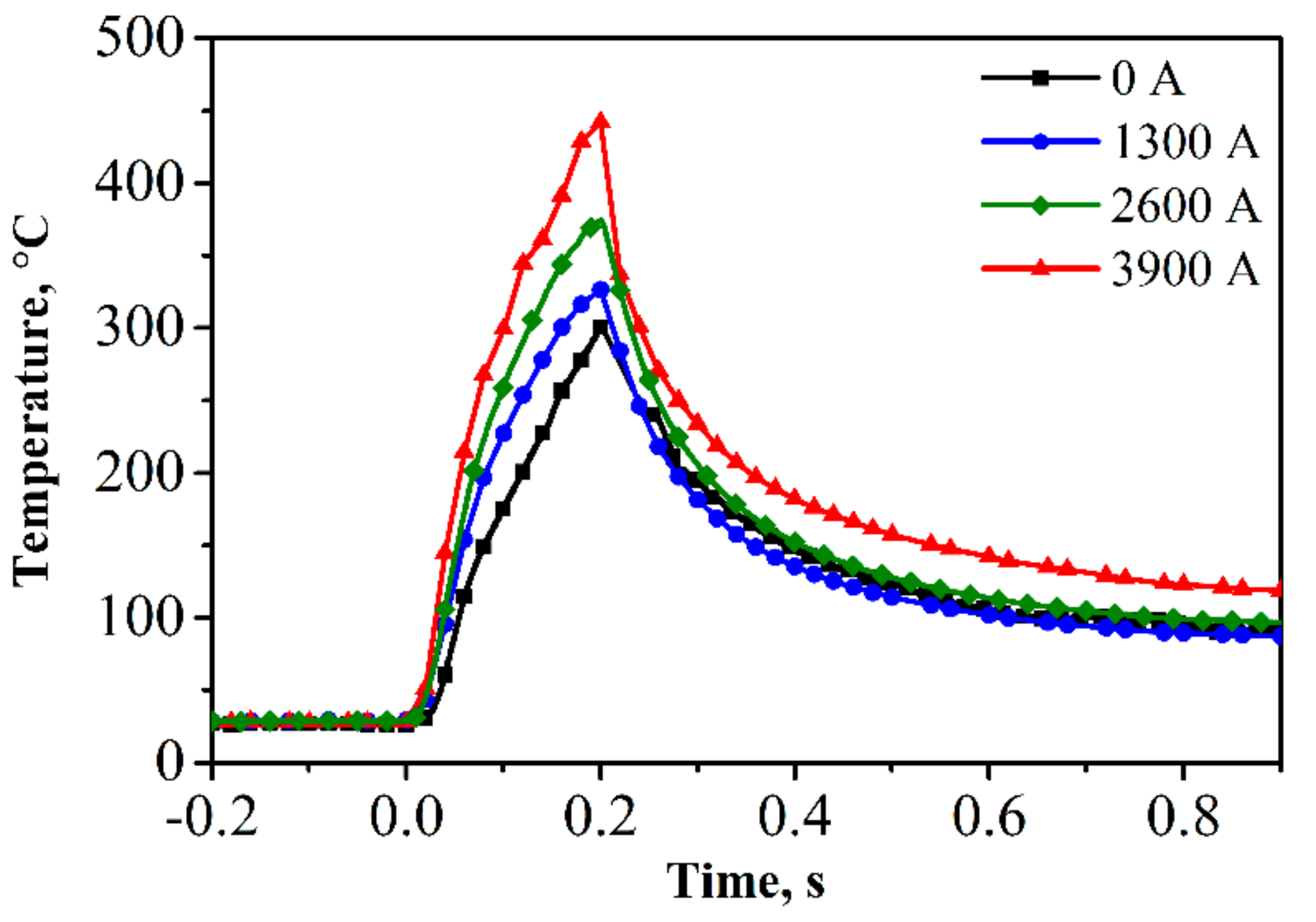
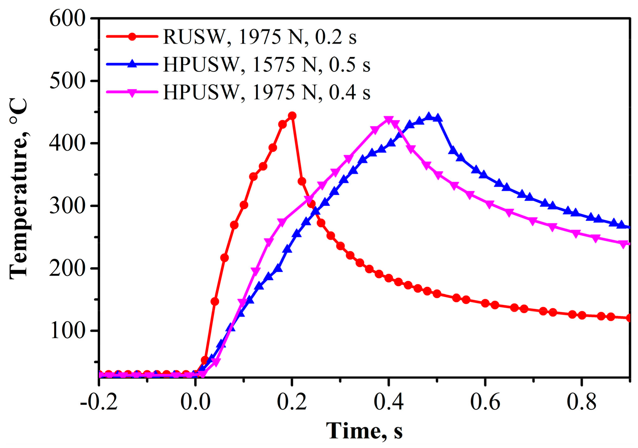
4.1. Interface Temperature
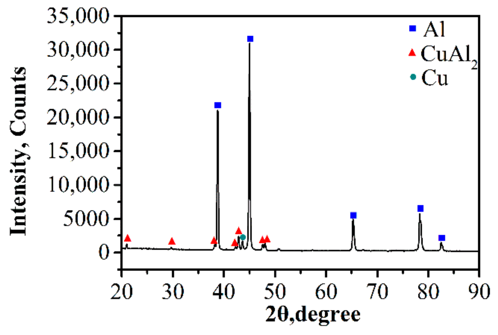
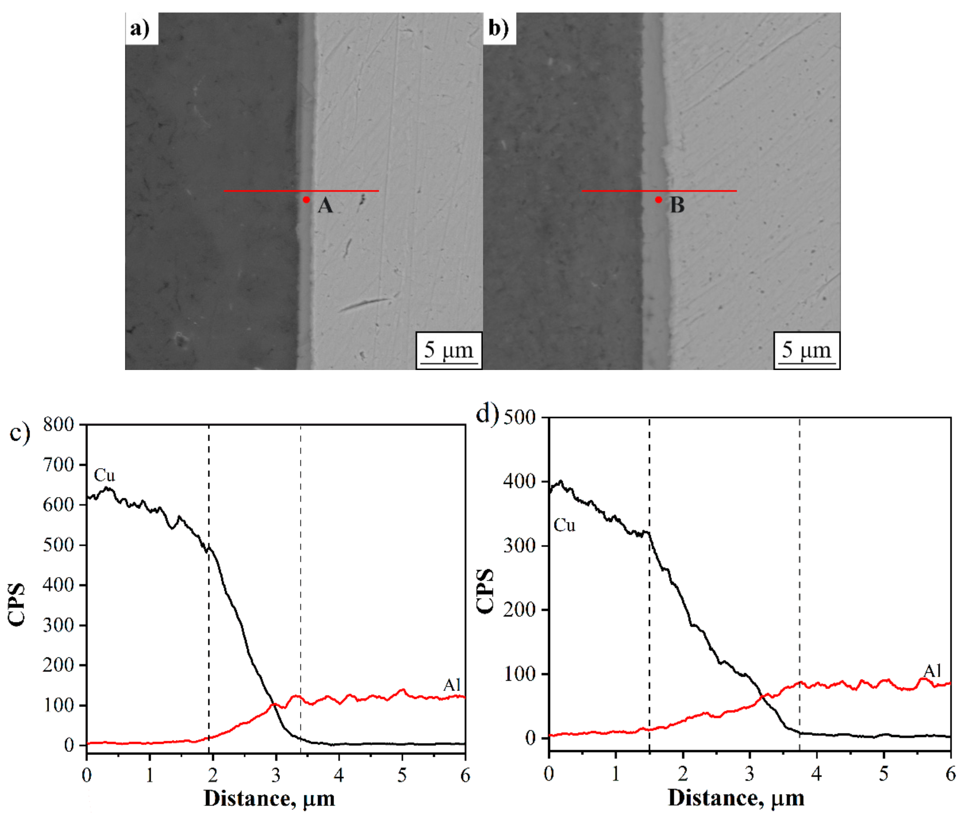
Figure 4 shows the measured temperature as the current changes from 0 to 3900 A. The results show that at the same welding time of 0.2 s, the measured peak temperature at the welding interface in RUSW is 445 °C, which is significantly higher than the interface temperature of 301 °C in conventional HPUSW. The peak temperatures with a current of 1300 A, 2600 A, and 3900 A at the welding time of 0.2 s are 328 °C, 380 °C, and 445 °C, respectively. This means that the temperature rises at a high gradient as the welding current increases, because the resistance heat QRSW has a quadratic relationship with the electric current, according to Equation (3). The higher interface temperature benefits interfacial diffusion, resulting in higher welding strength.
Figure 5 shows the values of the interface temperature during hybrid welding and conventional HPUSW, at different welding moments. It is evident that the peak interface temperature in hybrid welding is similar to that in conventional HPUSW under the same conditions (welding time of 0.4 s, clamping force of 1975 N, welding time of 0.5 s, and welding pressure of 1575 N). This demonstrates that the additional resistance heat can speed up the HPUSW process.

4.2. IMC Layer

During HPUSW of dissimilar joints, the thickness of the IMC layer determines the welding quality [20,21]. Figure 6a,b show backscattered images of the RUSW joint at tw = 0.2 s, FN = 1975 N, and HPUSW joint at tw = 0.5 s, FN = 1575 N, respectively. The thickness of the IMC layer in the joints prepared by hybrid welding and single ultrasonic welding is 1.5 μm and 2.2 μm, respectively. The interface temperature can be measured with good repeatability due to the proximity of the thermocouple to the center of welding spot and stable vibration amplitudes obtained under the same process parameters [22], which produces good repeatability in material vacancy concentration [23]. This results in good repeatability of the IMC thickness measurements. Although the interface temperature of the hybrid welding is the same as that of the conventional HPUSW, the duration of the hybrid welding is shorter, leading to a thinner IMC layer compared to the conventional HPUSW result.
The chemical composition of IMC in joints prepared by RUSW and conventional HPUSW was analyzed using EDS point analysis, and the results are shown in Figure 6c,d, respectively. The chemical composition at points A and B is 54.82 Al-45.12 Cu and 55.02 Al-44.98 Cu (by weight percentage (wt%)), respectively. This result demonstrates that the chemical composition of the IMC layer, in both the hybrid and conventional HPUSW methods, is primarily brittle Al2Cu alloy, according to the binary-phase diagram of Cu-Al [24]. In conclusion, the composition of the IMC layer is quite similar for joints prepared by both hybrid and conventional welding methods. However, the IMC layer is thinner in the hybrid welding approach due to the shorter duration of the welding process, producing better quality results.
X-ray diffraction analysis was performed on the Al side of the fracture surface to further evaluate the phase composition of RUSW, as shown in Figure 7. The results show that the IMC formed during hybrid welding is primarily composed of Al2Cu. Therefore, the XRD results are in agreement with the EDS results.

4.3. Weld Cross-Section

The mechanical behavior was also affected by materials penetration. Figure 8a,b show the profiles of the weld cross-section, for the hybrid welded joint at tw = 0.2 s and for conventional HPUSW joint at tw = 0.4 s, under clamping force of 1975 N. The joint cross-section after hybrid welding has no obvious defects, whereas, in a conventional HPUSW joint, cracks appear on the copper, just under the tip of the sonotrode. This happens because the material is under high-stress concentration below the edge of the sonotrode, due to the action of long-term ultrasonic waves. In addition, in the conventional HPUSW joint, cracks propagate from the base metal to the welding interface under high-pressure action, which reduces the area of the welding and allows the aluminum alloy to leak from the crack and get attached to the sonotrode tip. This effect decreases the welding quality and may even cause damage to the sonotrode [25].

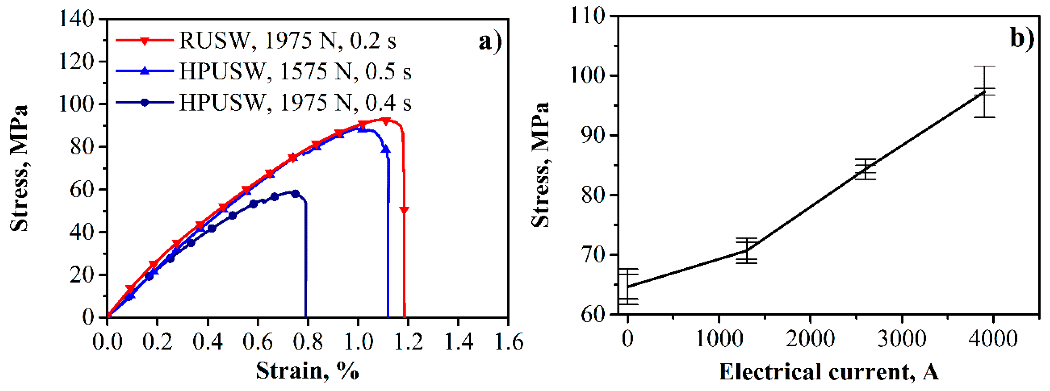
4.4. The Average Shear Stress

The experiments show that the average shear stress of the joint obtained with additional resistance heat reaches 97 MPa and elongation extends to about 1.2% (Figure 9a). This value is significantly higher compared to the joint prepared without resistance heat, under the same clamping force of 1975 N. In our previous work, the average shear stress of the RUSW joint was also slightly higher than the average shear stress of 90 MPa obtained in conventional HPUSW, at a pressure of 1575 N and welding time of 0.5 s, which are the welding conditions that produce the highest strength in HPUSW of Cu/Al joint [9]. This is attributed to the fact that the additional resistance heat can increase the interface temperature (Figure 4), reduce the thickness of the brittle IMC layer (Figure 6), and avoid cracks at the edges of the weld zone (Figure 8). The strength of the hybrid weld is also much higher than that of RSW, because of the lower interface temperature in RSW. As the resistance of the steel sonotrode is an order of magnitude higher than that of the workpieces, the resistance heat mainly occurs at the sonotrode/Cu interface, rather than at the Cu/Al interface.
It is well known that the repeatability in welding dissimilar materials is poor [6]. The poor repeatability could be related to the fact that IMC may not be uniformly distributed across the entire weld interface (Figure 6a,b) [26]. Moreover, differences in IMC layer thickness may exist in different regions of the weld. While there were issues with repeatability in this study, some general trends in weld strength were observed. Figure 9b plots the weld tensile strength against the current. Although there is a lot of scattering, the figure suggests that a high current can produce welds with increased tensile strength. The duration of hybrid welding is shorter than that of conventional HPUSW technique, and thus the period of ultrasonic excitation is shorter, reducing the risk of fatigue fracture [27].

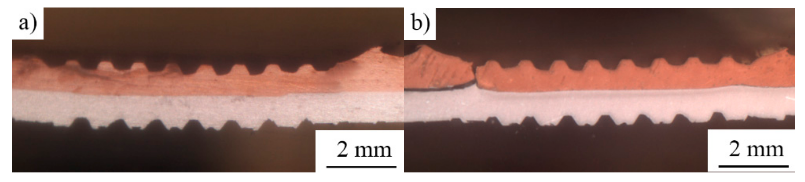
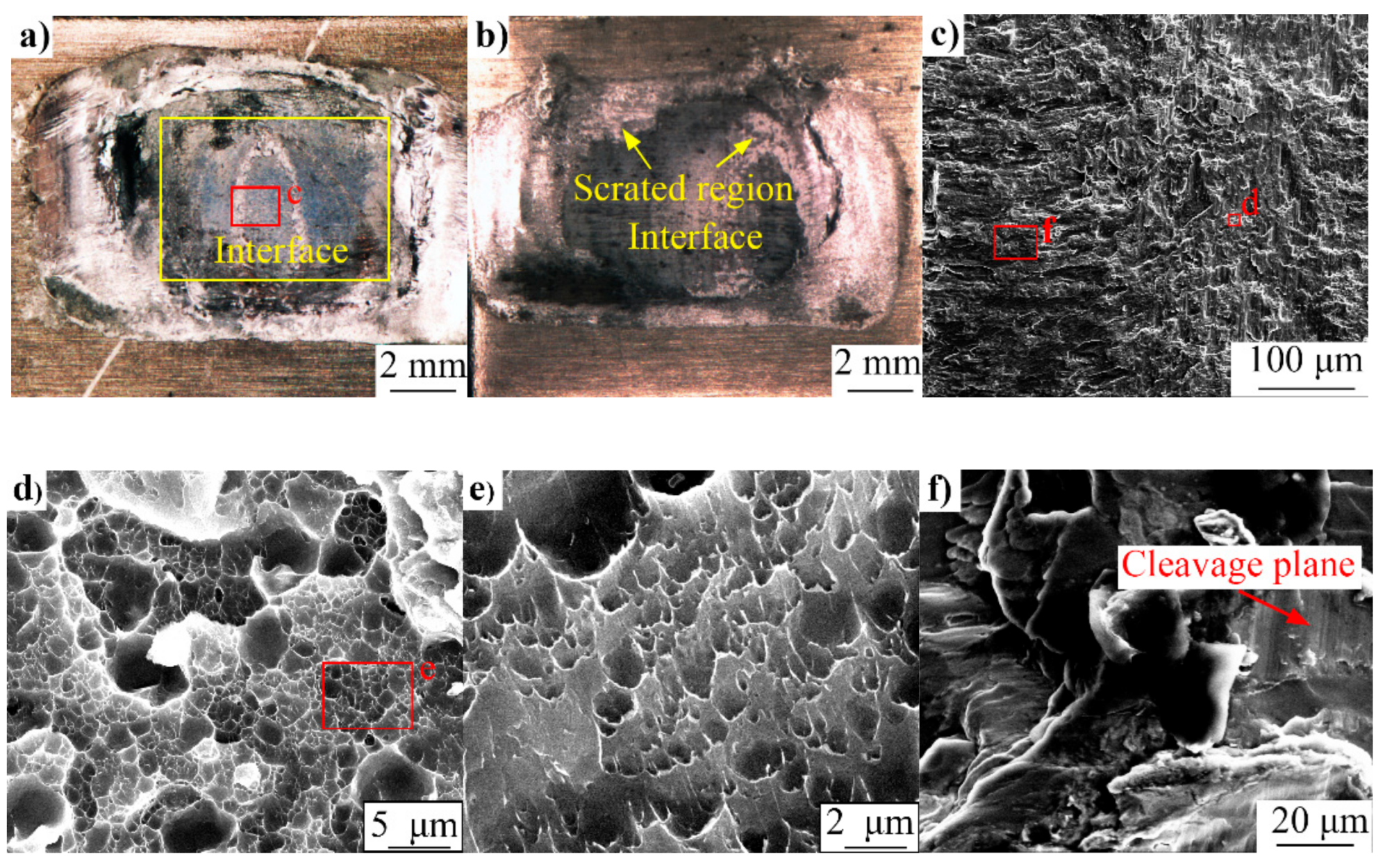
4.5. Fracture Morphology

Figure 10a,b show the macroscopic fracture morphology of the Cu/Al joint made by RUSW at 0.2 s and by conventional HPUSW at 0.4 s, under a clamping force of 1975 N on the Al side. Figure 10c is an enlarged view of Figure 10a, showing the microscopic topography of the fracture. It is observed that there are differences in fracture behavior. For the joint fabricated with RUSW, only welded regions are observed in the fracture surface. This demonstrates that the fracture of the hybrid welding joint occurs at the IMC of the Cu/Al interface, indicating high welding strength. In the case of a joint fabricated with HPUSW, some welded regions and scratched regions exist in the fracture surface (Figure 10b). There are two fracture models demonstrated in Figure 10c. From the enlarged view of the two regions (Figure 10e,f) from Figure 10c, it is obvious that a large number of dimples of different sizes are present in the c region, while there are some cleavage planes in the f region. These features indicate that the fracture of the RUSW is ductile–brittle type.

5. Conclusions

Dissimilar joints of pure copper and 6061-T6 alloys prepared by RUSW are investigated and compared to those prepared by the conventional HPUSW method. It is found that the additional resistance heat promotes the increase in interface temperature and reduces the thickness of the brittle IMC layer. The short duration of RUSW prevents the formation of cracks on the copper surface. As a result, the mechanical properties of the joint prepared by hybrid welding are significantly improved. Fracture surface morphology exhibits dimples and some cleavage planes, indicating a ductile–brittle hybrid fracture in RUSW.

Author Contributions

H.L. conceived, designed, and performed the experiments, and wrote the manuscript; B.C. contributed to the discussion of the experimental data, interpreted the results and revised the manuscript.

Funding

This work was supported by the National Natural Science Foundation of China (Grant No. 51175184).

Acknowledgments

The authors would like to acknowledge the kind assistance from Caiyou Zeng from the South China University of Technology.

Conflicts of Interest

The authors declare no conflict of interest.

References

  1. Peng, H.; Jiang, X.; Bai, X.; Li, D.; Chen, D. Microstructure and mechanical properties of ultrasonic spot welded Mg/Al alloy dissimilar joints. Metals 2018, 8, 229. [Google Scholar] [CrossRef]
  2. Pereira, A.B.; Cabrinha, A.; Rocha, F.; Marques, P.; Fernandes, F.A.; Alves de Sousa, R.J. Dissimilar Metals Laser Welding between DP1000 Steel and Aluminum Alloy 1050. Metals 2019, 9, 102. [Google Scholar] [CrossRef]
  3. Eslami, N.; Hischer, Y.; Harms, A.; Lauterbach, D.; Böhm, S. Influence of Copper-Sided Tin Coating on the Weldability and Formation of Friction Stir Welded Aluminum-Copper-Joints. Metals 2019, 9, 179. [Google Scholar] [CrossRef]
  4. Eslami, N.; Hischer, Y.; Harms, A.; Lauterbach, D.; Böhm, S. Optimization of process parameters for friction stir welding of aluminum and copper using the taguchi method. Metals 2019, 9, 63. [Google Scholar] [CrossRef]
  5. Zhou, K.; Yao, P. Overview of recent advances of process analysis and quality control in resistance spot welding. Mech. Syst. Signal Process. 2019, 124, 170–198. [Google Scholar] [CrossRef]
  6. Liu, G.; Hu, X.; Fu, Y.; Li, Y. Microstructure and mechanical properties of ultrasonic welded joint of 1060 aluminum alloy and T2 pure copper. Metals 2017, 7, 361. [Google Scholar] [CrossRef]
  7. Liu, J.; Cao, B.; Yang, J. Effects of vibration amplitude on microstructure evolution and mechanical strength of ultrasonic spot welded Cu/Al joints. Metals 2017, 7, 471. [Google Scholar] [CrossRef]
  8. Zhang, C.; Chen, D.; Luo, A. Joining 5754 automotive aluminum alloy 2-mm-thick sheets using ultrasonic spot welding. Weld. J 2014, 93, 131. [Google Scholar]
  9. Yang, J.; Cao, B.; He, X.; Luo, H. Microstructure evolution and mechanical properties of Cu–Al joints by ultrasonic welding. Sci. Technol. Weld. Join. 2014, 19, 500–504. [Google Scholar] [CrossRef]
  10. Zhao, Y.; Li, D.; Zhang, Y. Effect of welding energy on interface zone of Al–Cu ultrasonic welded joint. Sci. Technol. Weld. Join. 2013, 18, 354–360. [Google Scholar] [CrossRef]
  11. Ni, Z.L.; Ye, F.X. Weldability and mechanical properties of ultrasonic joining of aluminum to copper alloy with an interlayer. Mater. Lett. 2016, 182, 19–22. [Google Scholar] [CrossRef]
  12. Balasundaram, R.; Patel, V.K.; Bhole, S.D.; Chen, D.L. Effect of zinc interlayer on ultrasonic spot welded aluminum-to-copper joints. Mater. Sci. Eng. A 2014, 607, 277–286. [Google Scholar] [CrossRef]
  13. Macwan, A.; Kumar, A.; Chen, D. Ultrasonic spot welded 6111-T4 aluminum alloy to galvanized high-strength low-alloy steel: Microstructure and mechanical properties. Mater. Des. 2017, 113, 284–296. [Google Scholar] [CrossRef]
  14. Ni, Z.; Zhao, H.; Mi, P.; Ye, F. Microstructure and mechanical performances of ultrasonic spot welded Al/Cu joints with Al 2219 alloy particle interlayer. Mater. Des. 2016, 92, 779–786. [Google Scholar] [CrossRef]
  15. Dehelean, D.; Oanca, O.; Toma, C.; Dorohoi, C.; Budau, V.; Craciunescu, C. Advanced materials joining using a hybrid ultrasonic-electric resistance technique. J. Optoelectron. Adv. Mater. 2010, 12, 1935–1941. [Google Scholar]
  16. Yang, J.; Cao, B. Investigation of resistance heat assisted ultrasonic welding of 6061 aluminum alloys to pure copper. Mater. Des. 2015, 74, 19–24. [Google Scholar] [CrossRef]
  17. Li, H.; Cao, B.; Yang, J.; Liu, J. Modeling of resistance heat assisted ultrasonic welding of Cu-Al joint. J. Mater. Process. Technol. 2018, 256, 121–130. [Google Scholar] [CrossRef]
  18. Li, H.; Cao, B.; Liu, J.; Yang, J. Modeling of high-power ultrasonic welding of Cu/Al joint. Int. J. Adv. Manuf. Technol. 2018, 97, 833–844. [Google Scholar] [CrossRef]
  19. Lee, D.; Cai, W. The effect of horn knurl geometry on battery tab ultrasonic welding quality: 2D finite element simulations. J. Manuf. Process. 2017, 28, 428–441. [Google Scholar] [CrossRef]
  20. Samanta, A.; Xiao, S.; Shen, N.; Li, J.; Ding, H. Atomistic simulation of diffusion bonding of dissimilar materials undergoing ultrasonic welding. The International Journal of Advanced Manufacturing Technology; Springer: London, UK, 2019; pp. 1–12. [Google Scholar]
  21. Das, A.; Masters, I.; Williams, D. Process robustness and strength analysis of multi-layered dissimilar joints using ultrasonic metal welding. The International Journal of Advanced Manufacturing Technology; Springer: London, UK, 2019; Volume 101, pp. 881–900. [Google Scholar]
  22. Zhao, J.; Li, H.; Choi, H.; Cai, W.; Abell, J.A.; Li, X. Insertable thin film thermocouples for in situ transient temperature monitoring in ultrasonic metal welding of battery tabs. J. Manuf. Process. 2013, 15, 136–140. [Google Scholar] [CrossRef]
  23. Hu, T.; Zhalehpour, S.; Gouldstone, A.; Muftu, S.; Ando, T. A method for the estimation of the interface temperature in ultrasonic joining. Metall. Mater. Trans. A 2014, 45, 2545–2552. [Google Scholar] [CrossRef]
  24. Tan, C.; Jiang, Z.; Li, L.; Chen, Y.; Chen, X. Microstructural evolution and mechanical properties of dissimilar Al–Cu joints produced by friction stir welding. Mater. Des. 2013, 51, 466–473. [Google Scholar] [CrossRef]
  25. Badamian, A.; Iwamoto, C.; Sato, S.; Tashiro, S. Interface Characterization of Ultrasonic Spot-Welded Mg Alloy Interlayered with Cu Coating. Metals 2019, 9, 532. [Google Scholar] [CrossRef]
  26. Bhamji, I.; Preuss, M.; Moat, R.; Threadgill, P.; Addison, A. Linear friction welding of aluminium to magnesium. Sci. Technol. Weld. Join. 2012, 17, 368–374. [Google Scholar] [CrossRef]
  27. Carboni, M.; Annoni, M. Ultrasonic metal welding of AA 6022-T4 lap joints: Part II–Fatigue behaviour, failure analysis and modelling. Sci. Technol. Weld. Join. 2011, 16, 116–125. [Google Scholar] [CrossRef]
Figure 1. The principle of resistance heat-assisted high-power ultrasonic welding (RUSW).
Metals 09 00873 g001
Figure 2. Schematic of the resistances in the RUSW system.
Metals 09 00873 g002
Figure 3. (a,b) The RUSW machine setup; (c) configuration of the tensile-shear, and (d) temperature measurement tests setup.
Metals 09 00873 g003
Figure 4. Measured temperatures for various currents.
Metals 09 00873 g004
Figure 5. Measured temperature progress with welding time and pressure.
Metals 09 00873 g005
Figure 6. (a,b) Cu/Al interface in the RUSW and high-power ultrasonic welding (HPUSW) joints, respectively; (c,d) EDS results for the lines intersecting the points indicated in (a,b).
Metals 09 00873 g006
Figure 7. XRD patterns of the fracture surface.
Metals 09 00873 g007
Figure 8. Profile of weld cross-section (a) RUSW at 0.2 s, and (b) HPUSW at 0.4 s.
Metals 09 00873 g008
Figure 9. (a) The relationship between lap shear stress and strain; (b) the relationship between lap shear stress and electric current.
Metals 09 00873 g009
Figure 10. Fracture surface (a) RUSW at 0.2 s; (b) HPUSW at 0.4 s; (c) enlarge view of (a); (d) region d in (c); (e) enlarge view of (d); (f) region f in (c).
Metals 09 00873 g010

