Article

Finite Element Simulation and Process Optimization of JCO Forming for Extreme-Specification X80 Steel Line Pipes

1
School of Metallurgical Engineering, Anhui University of Technology, Maanshan 243002, China
2
CNPC Bohai Petroleum Equipment Manufacturing Co., Ltd., Tianjin 300450, China
3
School of Materials Science and Engineering, Yanshan University, Qinhuangdao 066000, China
*
Authors to whom correspondence should be addressed.
Metals 2026, 16(8), 845; https://doi.org/10.3390/met16080845
Submission received: 19 May 2026 / Revised: 22 July 2026 / Accepted: 23 July 2026 / Published: 3 August 2026
(This article belongs to the Special Issue Rolling and Forming of Alloys and Steels)

Abstract

The current internationally largest-diameter and thickest-wall oil and gas transmission line pipe of X80 grade (API Spec 5L) manufactured by longitudinal submerged arc welding (LSAW) is the X80 OD 1422 mm × 32.1 mm straight-seam LSAW pipe, which approaches the limit of manufacturing equipment capability. To overcome the 29-pass limitation of the conventional JCO (J-forming, C-forming, O-forming) forming process for steel pipes, this study conducts a three-dimensional finite element numerical simulation analysis based on ABAQUS 2022/Explicit (explicit dynamic finite element solver within the commercial finite element software Abaqus) to investigate the JCO forming process of this extreme-specification pipe. An innovative involute lower die is designed, enabling a reduction in the forming process to 25 passes. The residual stress and plastic strain distributions in the formed pipes from both the 25-pass and 29-pass processes exhibit consistent patterns, characterized by higher values at the surface layers and lower values in the core region, with the inner surface showing higher stress and strain levels than the outer surface. The maximum residual stress (231.7 MPa) and maximum plastic strain (0.03787) of the 25-pass pipe are slightly lower than those of the 29-pass pipe (231.9 MPa and 0.03859, respectively). In terms of geometric accuracy, the 25-pass process yields an opening gap of 118.8 mm, marginally better than the 118.98 mm of the 29-pass process, and produces a smoother outer circumference profile after forming. These results demonstrate the superiority of the 25-pass process with the novel involute die configuration. The subsequent engineering application validates that the established finite element model possesses high predictive accuracy and practical guidance value. This study provides a breakthrough solution to the technical challenge of excessive forming passes in the JCO forming of the extreme-specification X80 OD 1422 mm × 32.1 mm pipe, achieving a reduction in forming passes while maintaining forming quality, significantly improving efficiency, and reducing manufacturing costs.

1. Introduction

Against the backdrop of accelerating global energy transition, natural gas, as a key component of clean energy, requires long-distance, efficient, and safe transportation to ensure stable energy supply. Pipeline transport, with its advantages of large capacity, low energy consumption, low cost, and environmental friendliness, has become the predominant mode for cross-regional oil and gas transmission and serves as the “energy artery” of strategic energy corridors. In recent years, global oil and gas pipeline construction has exhibited a clear trend toward larger diameters, higher steel grades, thicker walls, and higher pressures. X80 steel grade, currently the most widely applied high-strength pipeline steel in major oil and gas transmission projects worldwide, offering a combination of high strength, high toughness, and good weldability, has become the preferred material for large-diameter transmission pipelines. The X80M OD 1422 mm × 32.1 mm longitudinal submerged arc welded (LSAW) pipe, given that the maximum diameter capacity of manufacturing equipment is 1422 mm and the wall thickness reaches 32.1 mm, represents the largest-diameter and thickest-wall X80 line-pipe LSAW pipe currently used in international engineering design and application [1,2,3,4,5,6,7].
Under conventional forming dies and matching process conditions, the forming of this extreme-specification pipe requires a narrow upper punch with a small curvature radius and a relatively large lower die opening, employing multiple press passes. Currently, more than 29 passes are required. However, such a large number of passes severely restricts manufacturing efficiency and increases production costs. Freire, J.L.d.F. et al. [8] reported that compared with the UOE (U-forming, O-forming, E-Expanding) forming method, the JCO incremental bending process can form thick-wall steel pipes with lower pressing forces, and the resulting out-of-roundness, straightness, and mechanical properties are essentially comparable to those of UOE pipes. Thome, M. et al. [9] established a generalized plane-strain two-dimensional finite element model using ABAQUS 2022 to simulate the entire sequence of pre-bending, forming, welding, and expanding for both UOE and JCOE (J-forming, C-forming, O-forming, E-Expanding) processes; their comparison indicated that JCO is preferable for thick-wall pipes. Mingjun Wen et al. [10] investigated the effect of single-pass forming width on forming efficiency, finding that a larger width of the single-pass forming die reduces the required number of passes and significantly improves efficiency. These studies provide references for approaches to reducing forming passes. For the X80M OD 1422 mm × 32.1 mm LSAW pipe, JCO forming is the preferred method for thick-wall pipe forming, and innovative die improvement is an effective way to overcome the limitations of pressing capacity.
During the forming of this specification, the springback is substantial, and the difficulty of plastic deformation increases markedly [11,12,13,14,15]. Under near-limit forming pressures, the selection of forming dies and the setting of pressing parameters become critically narrow, making it prone to localized under-pressing or over-pressing due to non-uniform plate strength or improper parameter settings. This leads to difficulties in controlling the geometric accuracy of the formed pipe and results in non-uniform stress distribution after forming. Moreover, the high-strength characteristics of the X80-grade material make it more sensitive to notches and stress concentration. Qingren Xiong et al. [16] studied residual stress measurements in various high-strength welded pipes for oil and gas transmission, pointing out that residual stress directly affects dimensional accuracy, load-bearing capacity, and fatigue safety while also emphasizing the significant fluctuation and strong dispersion of stress levels on the inner and outer surfaces. Ren, P. et al. [17] investigated the effect of residual plastic strain on fatigue failure mechanisms and life prediction of dented X80 pipelines, reporting that pre-strain induces notable work hardening in X80 material, with flow stress continuously shifting upward with increasing pre-strain and initial residual tensile stress growing linearly with pre-strain. R. R. Adigamov et al. [18], in their study on the influence of pipe forming on the mechanical properties of large-diameter steel pipes, noted that the open pipe shell after forming exhibits critical characteristic sections along the axial direction (punch edges, punch center, and overlapping zones), with different deformation amounts in each zone leading to non-uniform mechanical property distribution. Therefore, for the X80M OD 1422 mm × 32.1 mm LSAW pipe, while reducing the number of passes, it is imperative to control the non-uniformity of residual stress and other stress distributions.
Furthermore, during JCO forming of this extreme pipe, geometric defects such as excessive opening gap, large out-of-roundness, and peaking at the pipe ends are prone to occur. Pengchao Chen et al. [19] focused on the critical issue of girth weld failures in long-distance oil and gas pipelines, systematically analyzing the root causes and revealing that misalignment at the pipe ends is a major contributor to failure in large-diameter high-strength gas pipelines. Tovmasyan et al. [20], addressing the difficulty in precisely controlling the shell shape during step-by-step JCO forming, employed DEFORM-3D (Scientific Forming Technologies Corporation, Columbus, OH, USA) to perform numerical simulations of the JCO process, revealing the contact interaction characteristics between the blank and the forming dies in the deformation zone, and established a set of geometric parameter calculation methods, thereby improving the geometric accuracy of the formed shell. Lingzhi Xu et al. [21] proposed that JCO forming requires precise matching of die dimensions and control of the steel plate’s incremental feed, which can reduce out-of-roundness and residual stress fluctuations, thus improving dimensional accuracy. These studies provide a research framework for using numerical simulation to analyze and predict the geometric accuracy of steel pipes under different die configurations and process conditions.
To ensure quality stability in subsequent welding and to achieve low-stress control during field girth welding for this extreme-specification pipe, it is essential that the geometric dimensions of the formed pipe fall within a reasonable range meeting engineering standards, without compromising service life [22,23,24].
This study overcomes the excessive-pass issue of the X80 OD 1422 mm × 32.1 mm pipe under conventional forming processes by innovatively developing a JCO forming involute lower die with a dedicated profile. By increasing the upper punch width and curvature radius, decreasing the lower die opening, and increasing the pressing reduction, the forming passes are optimized from 29 to 25. Using finite element simulations, the residual stress and forming geometric accuracy of the pipe shells produced by the conventional 29-pass process and the innovative 25-pass process are compared. Engineering application validation is carried out to confirm the simulation results. The outcomes demonstrate that, while ensuring pipe safety and dimensional accuracy, this approach can substantially improve manufacturing efficiency, reduce die wear and production costs, and meet the demands of large-scale production.

2. Materials and Methods

2.1. Materials

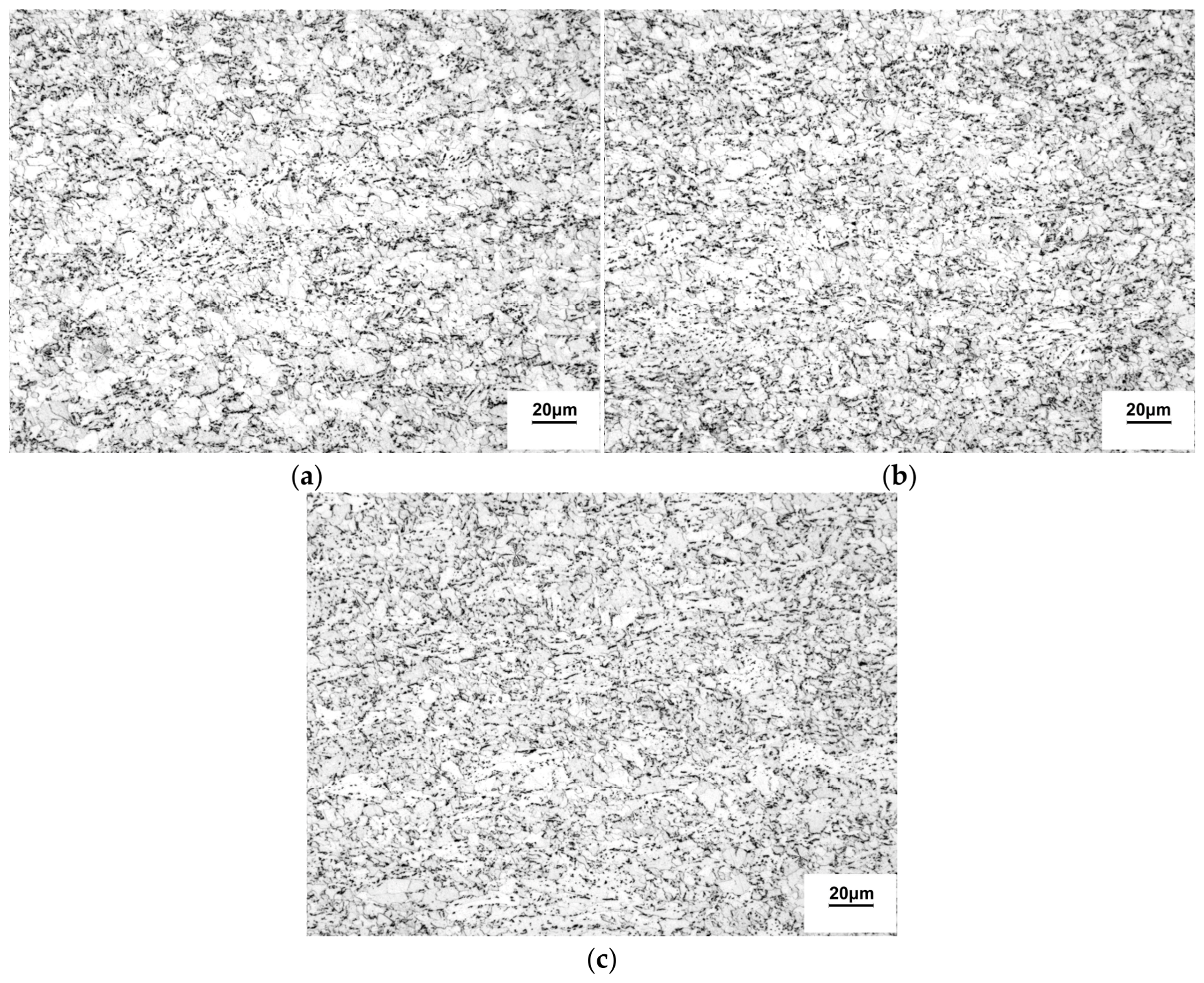
The research material is an X80-grade high-strength low-carbon microalloyed pipeline steel, with dimensions of 32.1 mm in thickness, 4333 mm in width, and 12,000 mm in length. The chemical composition and tensile properties of the material are presented in Table 1 and Table 2, respectively. In this study, 4% nitric acid ethanol solution was selected as the etchant for revealing the microstructure. The microstructure of the 32.1 mm thick X80 steel plate consists primarily of acicular ferrite (AF) and granular bainite (GB), with a certain proportion of polygonal ferrite (PF) and a small amount of finely dispersed MA constituents [25,26,27,28], as shown in Figure 1.

2.2. Forming Process Design

Die design for the pressing process is the core part of the JCO forming technology, which directly affects forming quality, accuracy, and efficiency. The die design must comprehensively consider the forming mechanical characteristics, material deformation behavior, process parameter optimization, and equipment conditions so as to ensure uniform stress distribution, controllable springback behavior, and satisfactory pipe shape accuracy during pressing [29].
The upper die (punch) is the component that directly applies the forming force, and its design is determined according to the target pipe diameter, plate thickness, and material properties. The curvature radius is generally close to the inner pipe diameter   R punch     R inner , which needs to balance the bending strain gradient and the risk of cracking. The width of the upper die affects the length of the contact zone; it is usually designed as an arc surface with moderate width to avoid excessive stress concentration or insufficient deformation [30].
The lower die (bottom die) serves as the two lower support points in the three-point bending of the steel plate and acts in conjunction with the upper die to induce local bending at the loading point of the plate. The opening setting of the lower die and the radius selection of the upper die jointly determine the quality of JCO forming. Typically, based on the specifications and material properties of the steel pipe, an appropriate lower die opening is calculated and selected, which is then adjusted through deflection compensation and trial pressing, ultimately achieving high-quality tube blank forming.
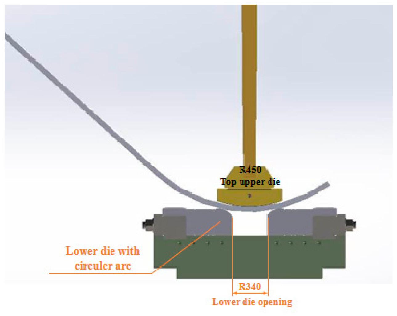
In the conventional circular arc lower die design, to ensure the pressing curvature of the steel pipe and considering the high steel grade and large wall thickness, the forming process adopts an R450 mm upper die matched with a 340 mm wide opening, with a step length of 142 ± 5 mm. According to the mechanical properties of the pipeline steel, 29 forming passes are adopted. The process parameters of the conventional 29-pass forming are listed in Table 3. Figure 2 shows the die design scheme of the conventional 29-pass forming process with a circular arc lower die.
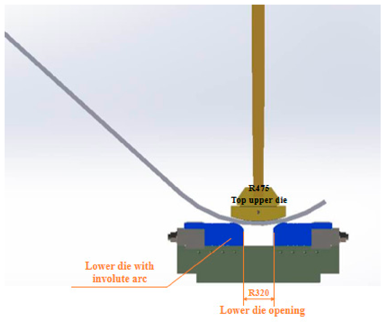
The innovative design of the steel pipe JCO forming die was developed for the forming of this ultra-large specification steel pipe with a proprietary curvature involute lower die through computer lofting simulation and pipe shape dimension calculation, considering the characteristics of plate specification, steel grade, forming machine pressing force, and oil cylinder stroke. The adoption of the involute lower die increased the distance between the pressing tangent points of the steel pipe from the original 417.6 mm to 425.3 mm, increased the upper die curvature radius from the original R450 to R475, reduced the lower die opening from the original 340 mm to 320 mm, increased the pressing step length from the original 142 mm to 165 mm, and reduced the forming passes from the original 29 to 25.
Through the successful design and development of an involute lower die, the forming with a large-curvature-radius upper punch was achieved under the same pressing force conditions. The large-curvature-radius upper punch enables the bent shape profile of the steel pipe to more closely approximate an ideal circular arc, while the involute lower die facilitates a smooth transition at the overlapping zones between successive bending steps. Thus, the geometric accuracy of the pipe is ensured while the number of pressing passes is reduced and forming efficiency is improved. The modified forming process parameters are listed in Table 4. Figure 3 presents the design scheme of the conventional circular-arc lower die for the 25-pass forming process.
The mold material is selected as 42CrMo ultra-high-strength alloy structural steel, which has the characteristics of high strength, good toughness, and the ability to bear heavy loads. Surface quenching treatment is carried out, with a hardness of HRC40–45, a profile tolerance error of ≤0.05 mm, and a surface roughness of Ra 1.6–3.2 μm, ensuring uniform contact and forming accuracy. The mold structure shall have sufficient stiffness to avoid elastic deformation under high pressure, affecting forming accuracy.
Centering adjustment is performed during mold installation to ensure the accurate position of the upper die and lower die in three-dimensional space. The mold gap shall be dynamically adjusted according to the plate thickness to avoid scratches caused by being too tight or affecting the transmission of forming force due to being too loose. The mold profile and process parameters are fine-tuned through a pressure test, especially the compensation and correction for springback and peak effects.

2.3. Finite Element Model Construction

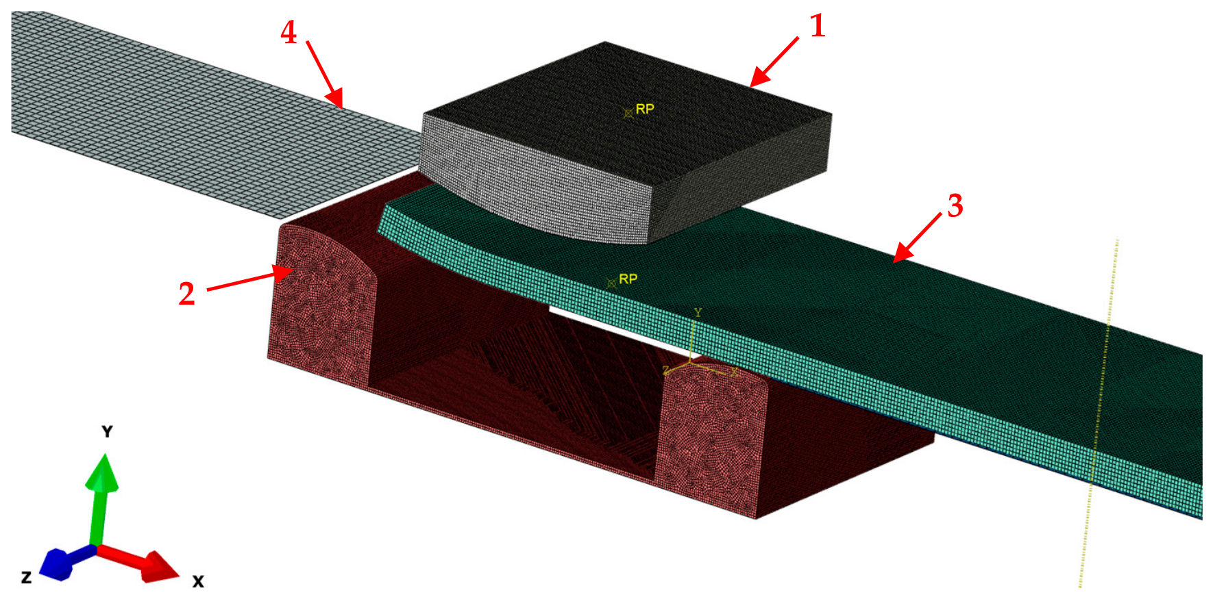
Based on the ABAQUS/Explicit platform, a three-dimensional dynamic explicit model for JCO forming was established [31,32,33,34], as shown in Figure 4. The model consists of four components: the upper die (part 1 in Figure 4), the lower die base (part 2 in Figure 4), the deformable steel plate (part 3 in Figure 4), and the forming support frame (part 4 in Figure 4).
The deformable part is meshed with 104,706 elements. The meshing specifications are as follows: the deformable steel plate is discretized with C3D8R 8-node linear hexahedral elements, adopting the reduced integration algorithm with hourglass control enabled; the dies and supporting structures are uniformly modeled with R3D4 4-node three-dimensional bilinear rigid quadrilateral elements. Table 5 presents the boundary condition settings and material property parameters used in the simulation.
The support mechanisms at both ends mainly function to support the steel plate during the JCO forming process, and their structural details have a negligible effect on the stress and strain distribution of the steel plate throughout forming. To simplify the model, they are simplified as discrete rigid planes. In accordance with Saint-Venant’s principle, under the premise of static equivalence, the distributed force system is simplified into a concentrated force system. This approach reduces model complexity and computational resource consumption without altering the overall mechanical response. Let the resultant force acting on the support mechanism be F, and let the action area of the distributed force be A. The simplified concentrated force FC satisfies FC = F, with its action point located at the equivalent action point of the support mechanism.
The upper and lower pressing dies are designed in full 1:1 scale to accurately simulate the contact and loading process between the dies and the steel plate. Corresponding three-dimensional discrete rigid models are constructed according to the geometric shape and dimensions of the dies, ensuring that the surface flatness and dimensional accuracy of the die surfaces meet practical production requirements.
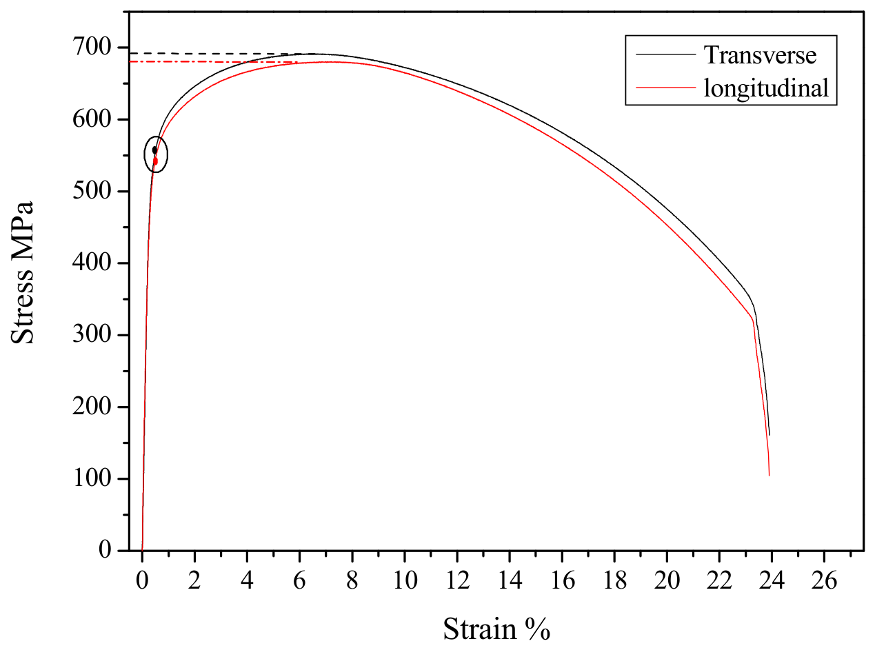
Tensile tests were carried out on the X80 line pipe steel plate with the specification OD1422 × 32.1 mm, and the measured tensile curves are presented in Figure 5. The points within the circled marker represent the transverse and longitudinal yield points of the steel plate.The transverse yield strength was measured as 556 MPa, while the longitudinal yield strength was 545 MPa, with a minor difference of only 11 MPa between the two directions. Given this small discrepancy, the material was approximated as isotropic when defining the numerical simulation parameters.
During the pressing process, full fixed constraints are applied to the left and right support plates and the lower die to simulate the actual fixed state of the die. According to the principle of mechanical equilibrium, the fixed constraints ensure that the die does not displace or rotate when bearing the pressure of the upper die, providing a stable boundary for the steel plate forming. In the finite element model, the fixed constraints are realized by restricting the displacement and rotation degrees of freedom of the die nodes in the X, Y, and Z directions. During pressing, the upper die only releases the degree of freedom in the Y direction and moves down by a set distance Y1; during lifting, it only releases the degree of freedom in the Y direction and moves up by a set distance Y2. The movement trajectory and distance of the upper die have a significant impact on the steel plate deformation, and its movement mode is set according to the actual production process parameters. Let the movement speed of the upper die be v and the pressing time be t; then, the downward distance is Y1 = v × t (t is the pressing time), and the upward distance is Y2 = v × t1 (t1 is the lifting time). Only the degree of freedom in the Y direction is released for the central axis of the steel plate pressing, allowing the steel plate to deform in the vertical pressing direction and restricting displacements in other directions to ensure stability. After each pressing, the steel plate moves along the X-axis by a specified step length X1 to simulate the intermittent feeding movement. The movement of the steel plate in the X direction is realized by adjusting the node coordinates; during the pressing stage, the displacement of the steel plate nodes in the X direction is constrained, i.e., ux = 0; after pressing is completed, the X coordinates of the nodes are updated according to the moving step length X1. A gravitational acceleration of 9.81 m/s2 is set for the steel plate along the Y direction to fully consider the impact of gravity on the steel plate pressing process. A dynamic explicit analysis step configured with multibody dynamics settings is adopted to fully reproduce the JCO forming process.

2.4. Engineering Application Validation of the Forming Process

A forming and manufacturing experiment was carried out using JCO forming (PPF6500/135H) equipment (equipment supplier: Hubei Sanhuan Forging Press Equipment Co., Ltd., Huangshi, China). The equipment consists of a 6-cylinder CNC bending forming machine host, dies, conveying roller table, front material supporting machine, front feeding machine, rear material supporting machine, rear feeding machine, side discharging machine, CNC system, and electrical control system. The maximum forming force is 6500 kN, and the oil cylinder stroke reaches 1700 mm.
X80 pipeline steel plates were used in the experiment, with dimensions of 4333 mm in width, 12,000 mm in length, and 32.1 mm in thickness. According to the process design, the traditional circular arc lower die (R450/V340) and the optimized involute lower die (R475/V320) were installed. The upper die and lower die were subjected to precise centering adjustment in three-dimensional space to ensure that the pressing center line coincides with the steel plate axis. The die gap was dynamically calibrated according to the plate thickness to avoid eccentric load or asymmetric deformation. The pressing parameter sequences of two processes (25 passes and 29 passes) were input, including step length, pressing depth, pressure holding time, etc., and the hydraulic system was pressure calibrated to ensure that the actual output was consistent with the set value.
The experiment adopted the JCO process of segmental pressing and progressive forming, and the specific process is as follows:
Steel Plate Feeding and Initial Positioning: The steel plate was stably transported to the forming station by the front feeding machine, and the positioning system was used to ensure that the deviation between the steel plate center line and the die center line was less than ±1 mm. Both ends of the steel plate were lifted by the hydraulic support mechanism to keep a horizontal state.
Pressing Operation: The upper die moved down to the preset pressing depth (200 ± 5 mm or 216 ± 5 mm) to complete the first J-shaped bending. After holding pressure for 3 s, the upper die returned, and the steel plate stepped axially (142 ± 5 mm or 165 ± 5 mm) to the next pressing position. Then, multi-pass cyclic pressing was carried out to perform C-shaped and O-shaped bending in turn. In the last 3 passes, the strategy of “gradually reducing pressing depth + local fine adjustment” was adopted to actively compensate for the springback deviation caused by the free boundary effect at the plate end, effectively suppressing the peak phenomenon at the open end.
Discharging After Forming: After forming was completed, the side discharging mechanism moved the tube out of the station, and the X80 ultra-large specification steel pipe blank was obtained after forming.

3. Analysis and Discussion of Simulation Results of the Forming Process

3.1. Analysis and Discussion of Numerical Simulation Results of Stress and Strain

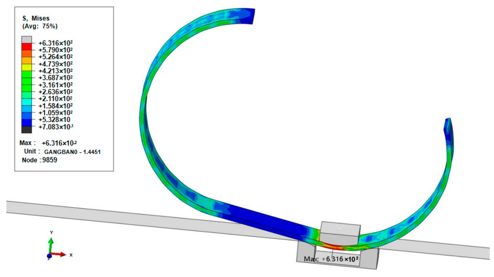
Using the conventional circular-arc lower die with an R450 upper punch, the 29-pass forming process was simulated. As shown in Figure 6, the maximum stress generated during the pressing process is 631.6 MPa, which occurs at the stage when the pressing stroke reaches its maximum. This maximum stress is located in the edge region of the steel plate and is distributed near both the inner and outer wall surfaces, as illustrated in Figure 6. The simulation results indicate that, during each pressing pass, when the pressing action reaches the maximum stroke, both the inner and outer wall surfaces exhibit simultaneously high stress characteristics, demonstrating that this phenomenon is repeatable and regular.
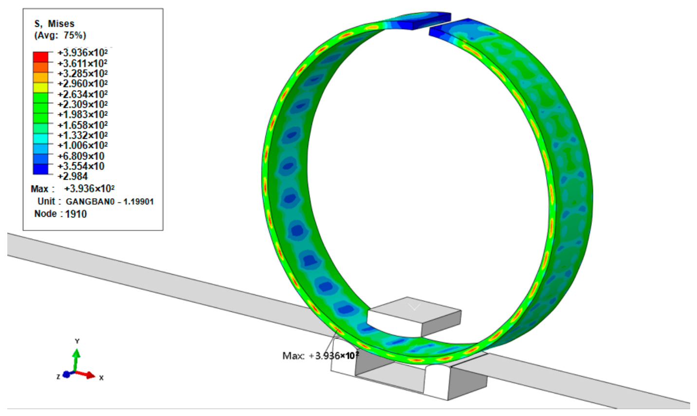
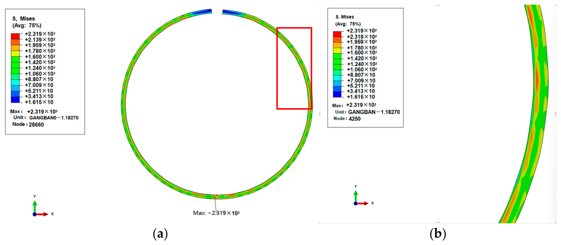
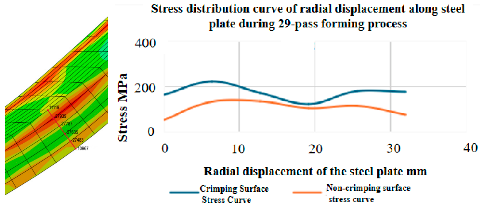
After the completion of the 29-pass pressing process, the residual stress distribution in the steel pipe is shown in Figure 7. The maximum residual stress reaches 393.6 MPa, which is located at both ends of the pipe after forming and situated at the center of the wall thickness. Since the edge regions at the two ends of the pipe are in a free state and subjected to compressive deformation, the surface residual stress at these locations cannot fully reflect the true stress state inside the pipe. Therefore, further analysis is required on the stress distribution at the mid-length cross-section along the longitudinal direction of the pipe. The residual stress distribution on this cross-section is presented in Figure 8, and Figure 9 shows the radial distribution curve of residual stress from the inner wall to the outer wall at the mid-length cross-section after forming. The results indicate that the maximum residual stress on this cross-section is 231.9 MPa, which occurs at the inner wall surface. The stress distribution along the wall thickness direction exhibits a pattern of higher values on both the inner and outer surfaces and lower values at the center of the wall thickness.
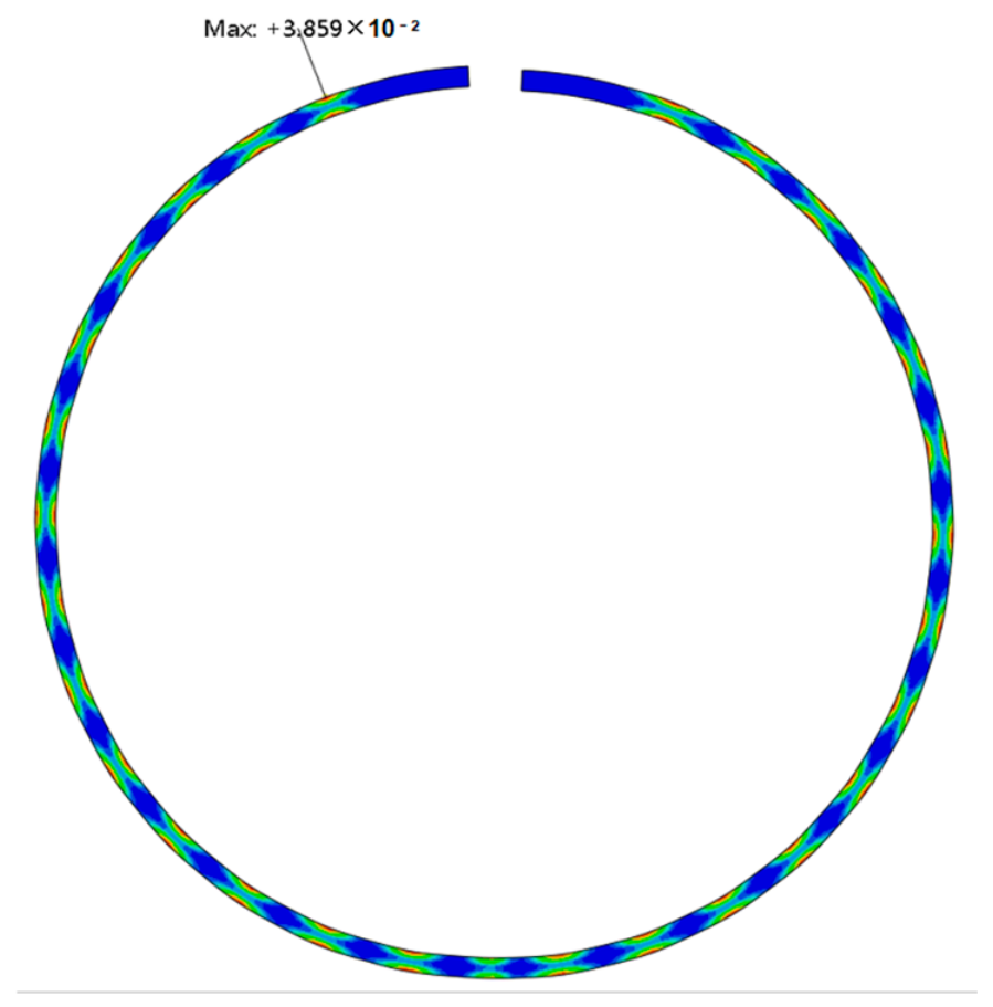
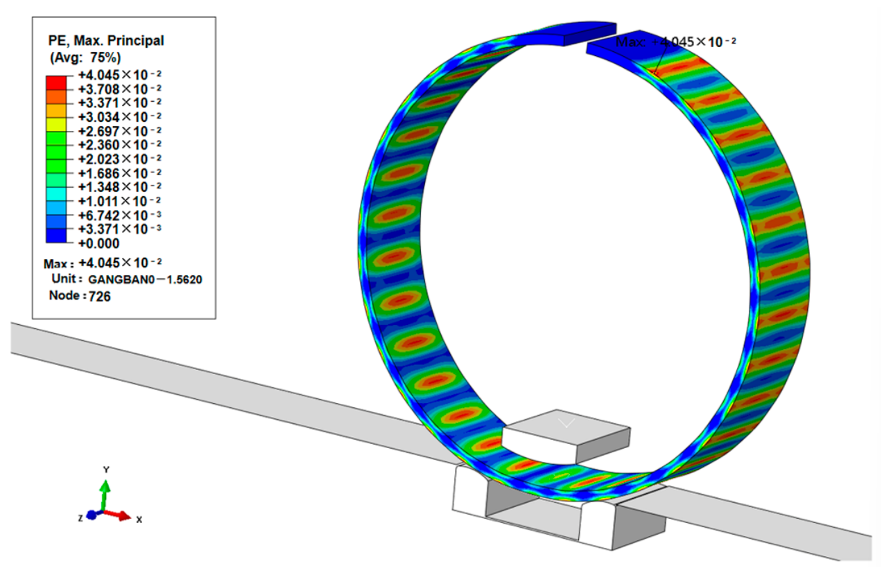
The plastic strain distribution in the steel pipe after forming is shown in Figure 10. The maximum plastic strain reaches 0.04045, which occurs at the outer surface regions near both ends of the pipe, where the degrees of freedom in deformation are relatively high. To examine the actual deformation state of the main body region of the pipe, the strain distribution at the mid-length cross-section was further analyzed (Figure 11). The maximum plastic strain on this cross-section is 0.03859, which is mainly concentrated in the upper and lower surface layers along the thickness direction; the plastic strain in the central region of the wall thickness is relatively lower. Moreover, the high-strain zones correspond to the contact positions between the die and the steel plate during the pressing process. The high plastic strain leads to more significant strain hardening on the inner and outer surfaces compared with the wall-thickness center, which consequently results in the maximum residual stress in these regions, as also shown in Figure 8.
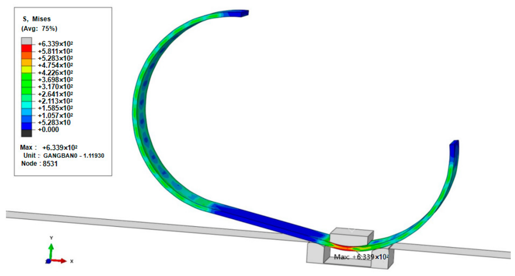
Using the innovative involute lower die with a dedicated curvature and the upper punch with a larger arc radius of R475, the 25-pass forming process was simulated. As shown in Figure 12, the maximum stress generated during the 25-pass pressing process is 633.9 MPa, which, similar to the 29-pass case, occurs at the stage when the pressing stroke reaches its maximum and is located near the outer wall surface at the edge of the steel plate; the inner wall surface also exhibits a relatively high stress level at this stage.
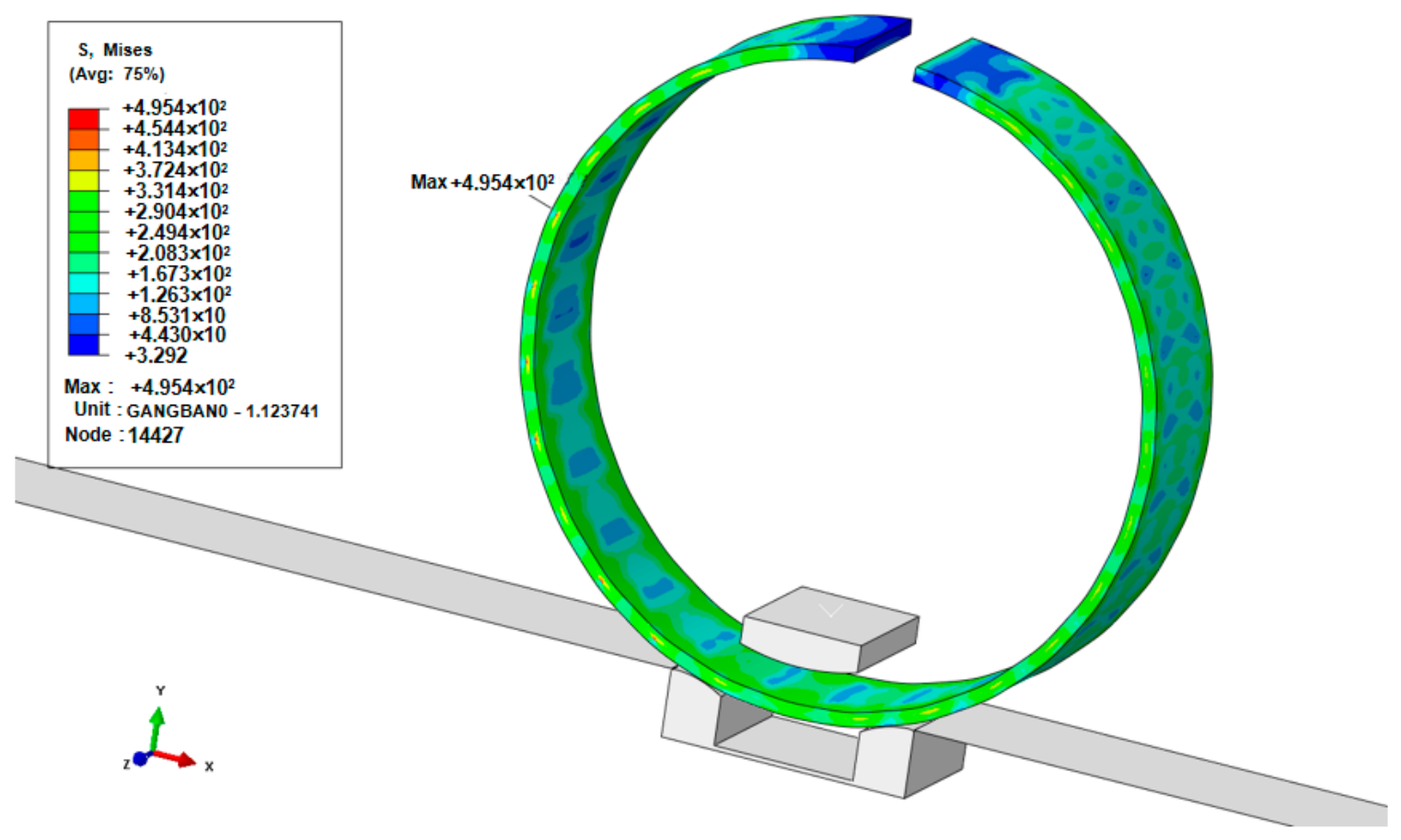
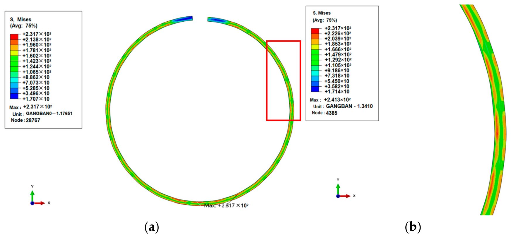
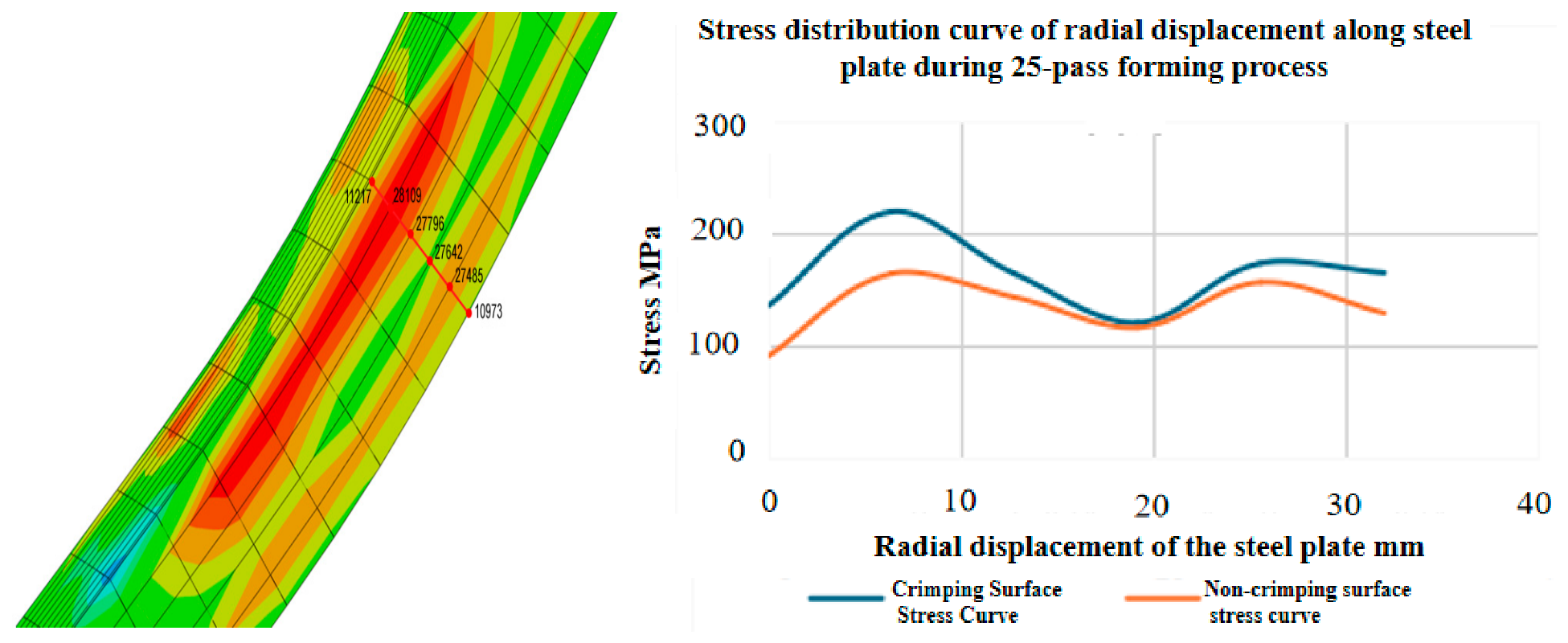
After the completion of the pressing process, the residual stress distribution in the steel pipe is shown in Figure 13. The maximum residual stress at the center of the wall thickness at both ends of the pipe is 495.4 MPa. The residual stress distribution on the mid-length cross-section of the pipe is presented in Figure 14. Figure 15 shows the radial distribution curve of residual stress from the inner wall to the outer wall at the mid-length cross-section after forming. The results indicate that the maximum residual stress on the mid-length cross-section is 231.7 MPa, which is located in the upper and lower regions along the thickness direction, with relatively lower stress in the central region, and is concentrated at the contact positions with the die during pressing.
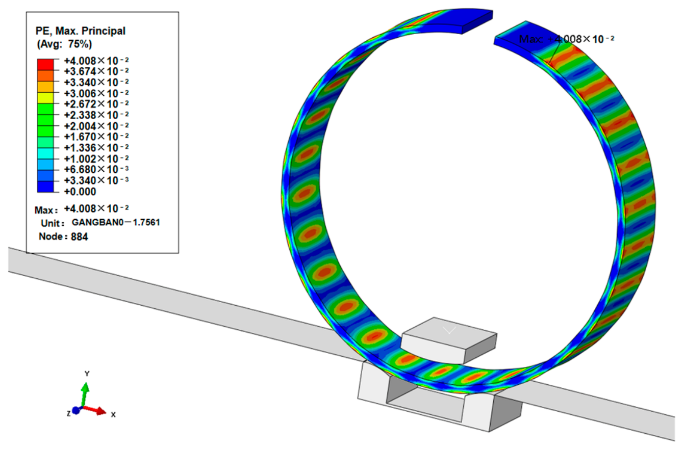
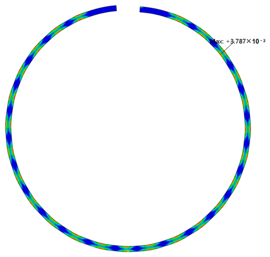
After the completion of the 25-pass pressing process, the plastic strain distribution is shown in Figure 16. The maximum plastic strain is 0.04008, which, similar to the 29-pass case, also occurs at the outer surface regions near both ends of the pipe. For the mid-length cross-section, the maximum plastic strain is 0.03787 and appears on the inner wall surface. Same as the 29-pass case, the strains in the regions near the upper and lower surfaces along the thickness direction are high, while the plastic strain in the central region of the wall thickness is relatively low, as shown in Figure 17.
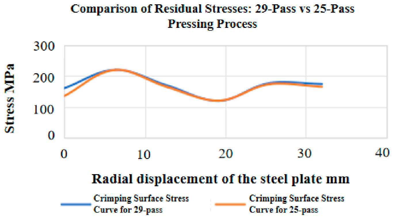
Under the two pressing processes of 29 passes and 25 passes, the residual stress and plastic strain distributions in the steel pipe exhibit a highly consistent spatial pattern (Figure 18): In both cases, higher stress and strain values are observed in the regions near the inner and outer wall surfaces, while the values in the central region of the wall thickness are relatively lower; moreover, the stress and strain levels on the inner wall surface are generally higher than those on the outer wall surface. In addition, both the high-stress and high-strain regions are distinctly concentrated at the locations in direct contact with the die during the pressing process. This common distribution characteristic is mainly attributed to the significant bending deformation experienced by the plate during pressing. The outer wall surface undergoes circumferential tension, while the inner wall surface undergoes circumferential compression. After unloading and springback, relatively high residual tensile stress and residual compressive stress (or greater accumulation of plastic strain) are formed near the inner and outer surface regions, respectively. The central region of the wall thickness lies in the elastic–plastic deformation transition zone, where the deformation is relatively small, resulting in lower stress and strain levels [35]. Meanwhile, the inner wall surface is generally subjected to more direct compression and friction during forming, and the curvature change tends to be larger, leading to more severe plastic deformation in this region; consequently, the residual stress and plastic strain levels on the inner wall surface are typically higher than those on the outer wall surface. The strong local constraints and friction forces at the contact regions between the die and the plate significantly inhibit material flow, causing pronounced stress and strain concentrations at these locations, which become critical high-value zones in both processes.
The simulation results show that the maximum residual stress on the pipe cross-section for the 25-pass process (231.7 MPa) is slightly lower than that for the 29-pass process (231.9 MPa). In terms of plastic strain, the maximum plastic strain for the 29-pass process (0.03859) is higher than that for the 25-pass process (0.03787), indicating that a greater number of forming passes results in strain accumulation. The 25-pass process enables the formed pipe to achieve lower residual stress, which is more favorable for ensuring service safety. Moreover, the lower plastic strain is beneficial for suppressing strain hardening accumulation during forming [36]. This is particularly advantageous for ultra-large wall-thickness steel pipes, as it helps reduce the property differences along the thickness direction and improves the workability of the pipe during subsequent expanding processes.
The simulation results demonstrate that the two processes are highly consistent in the fundamental governing mechanisms that determine component performance and shape. The mechanical state distributions are identical, with both residual stress and plastic strain exhibiting the typical “higher at the surface layers and lower in the core region” pattern, and the values on the inner wall being slightly higher than those on the outer wall. This confirms that both processes follow the same dominant bending-forming mechanism.
At the level of critical stress and strain indicators, the 25-pass process exhibits relatively superior performance. Specifically, its maximum residual stress is reduced by 1% compared with the 29-pass process—a subtle but critical difference indicating that the 25-pass process achieves better control over internal stresses during forming. Meanwhile, in terms of plastic strain, the maximum plastic strain of the 25-pass process is 1.9% lower than that of the 29-pass process, further reflecting the enhanced stability and efficiency of the 25-pass process in material shaping. This results in a more rational internal structural evolution after forming and reduces the potential quality risks that may arise from excessive plastic deformation.

3.2. Analysis and Discussion of Numerical Simulation Results of Geometric Accuracy

The primary geometric parameters of the steel pipe after JCO forming include the opening gap (the distance between the two edges of the formed steel plate), peaking (the deviation of the pipe profile from the ideal circular arc), and out-of-roundness. The opening gap is closely related to the stress distribution on both sides of the weld seam after pipe welding. A larger opening gap results in higher residual stresses on both sides of the weld, and the stresses acting on the welding heat-affected zone—the weakest region of the pipe—increase the susceptibility to stress corrosion cracking [37,38]. Although peaking after forming can be partially corrected during the subsequent expanding process, the magnitude of peaking after JCO forming has a significant influence on the final dimensional accuracy of the pipe. For high-strength, ultra-large wall-thickness steel pipes, due to their high strength and large wall thickness, the corrective capability of the subsequent expanding process for this parameter is very limited. Therefore, to ensure the final dimensional accuracy of peaking, precise control must be achieved during JCO forming. Moreover, peaking directly affects the misalignment at the girth weld during pipe butt-welding, which in turn influences the residual stress level of the girth weld. The greater the peaking, the more difficult it is to control the misalignment, and in severe cases, it may even prevent proper butt joining. The fully automatic girth welding process imposes unprecedentedly stringent requirements on peaking. Out of roundness after JCO forming is also one of the important parameters affecting the geometric accuracy of the pipe, and its calculation formula is as follows:
e   =   D max D min D avg
where D denotes the diameter.
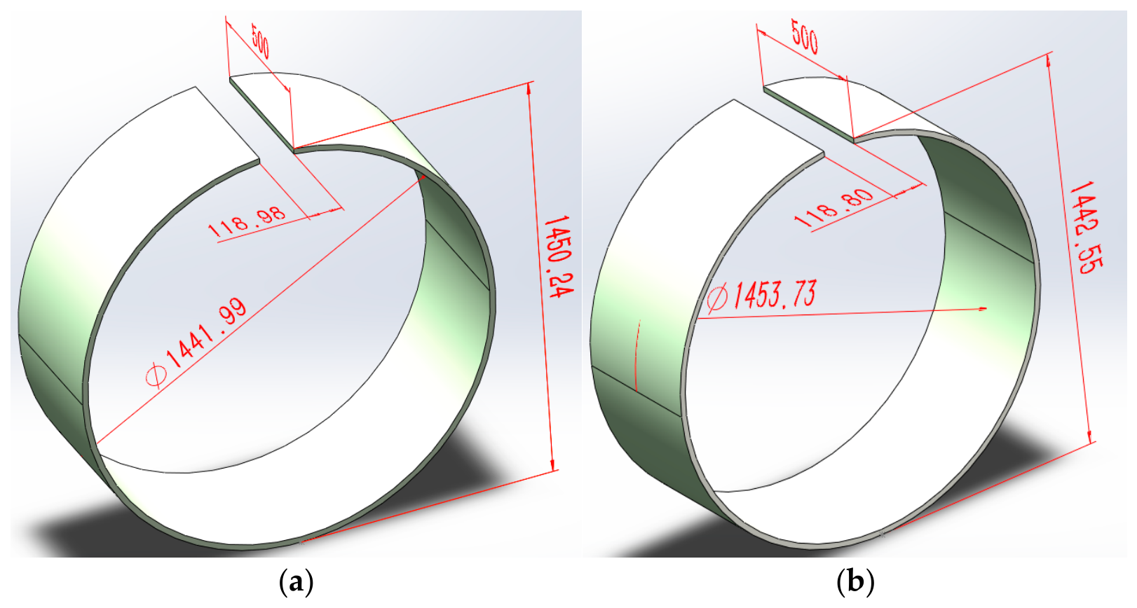
A quantitative evaluation was conducted on the forming simulation results of the 29-pass pressing process. Figure 19a shows the three-dimensional geometry derived from the numerical simulation of the 29-pass forming process. Based on dimensional measurements of this model, the opening gap of the formed pipe shell is 118.98 mm, and the out of roundness calculated from the results is approximately 0.00571. Using the same method, the geometric accuracy of the forming simulation results for the 25-pass pressing process was quantitatively analyzed, as shown in Figure 19b. The opening gap of the pipe shell formed by the 25-pass process is 118.80 mm, which is smaller than that of the 29-pass process. This indicates that the process route combining the involute lower die with the large-curvature-radius upper punch achieves a smaller and superior opening gap with fewer forming passes.
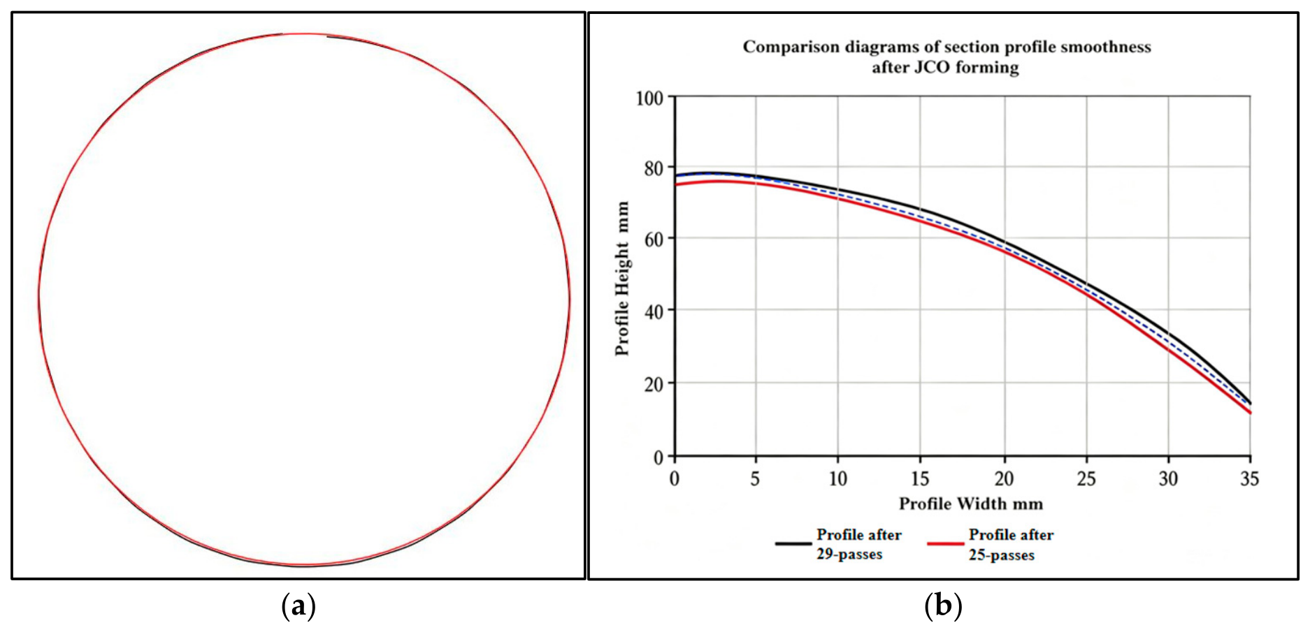
The simulated pipe models from the two forming processes are placed in the same coordinate system with coincident circle centers to compare the smoothness of their outer circular profiles, as shown in Figure 20.
Figure 20a presents the full view of the simulated pipe models for both processes. On the whole, the outer circular profiles of the pipes formed by the two processes are highly consistent. However, the partially enlarged view of the outer profiles in Figure 20b reveals detailed differences: The red line corresponds to the 25-pass process, the black line to the 29-pass process, and the blue dashed line to the ideal circular arc. The outer profile of the 25-pass formed pipe is smoother, while local sharp peaks appear on the outer profile of the 29-pass formed pipe, demonstrating that the 25-pass process yields a superior geometric profile.
This improvement arises because the 25-pass process employs an involute lower die matched with an upper die with a large curvature radius of R475. Compared with the 29-pass process, which adopts a conventional circular-arc lower die paired with an R450 upper die, the R475 upper die features a longer pressing arc length. Coupled with an appropriate pressing depth, the extended arc length enables a smooth transition across the overlapping transition zones between adjacent forming steps, thereby improving the as-formed profile shape and optimizing pipe peaking—a key precision parameter for steel pipe forming.
In terms of geometric accuracy after forming, the simulated geometric accuracy of both processes meets the requirements. The opening gap of the 25-pass forming process is slightly superior to that of the 29-pass process, with an improvement rate of 0.15%, and both fall within the design range of 80 mm to 150 mm. Moreover, compared with the 29-pass process, the 25-pass process yields a smoother outer circumferential profile, indicating that macroscopic dimensions and shape have been effectively controlled despite the reduction in the number of passes. Furthermore, comparing the out-of-roundness values, the 29-pass process yields 0.00571, while the 25-pass process yields 0.00772, indicating a slightly better circularity control for the former. However, the absolute difference between the two is minor, and the out-of-roundness after forming can be significantly improved and optimized during the subsequent mechanical cold-expanding process, with negligible impact on the final product performance [39]. From a macroscopic perspective of the forming results, both the 29-pass and 25-pass processes achieve a high level of quality and are well suited to the process requirements, implying that both can precisely shape the product to the desired geometry, ensuring high consistency and accuracy in the final dimensions.
The innovative design of this die enables a safe reduction in forming passes from 29 to 25. The direct benefits are manifested as follows: The reduced number of loading cycles alleviates the accumulation of plastic strain and internal damage within the material, thereby lowering the residual stress of the formed pipe body. As the total elastic strain energy driving springback is consequently diminished, the opening clearance of the formed steel pipe is improved [40,41]. Furthermore, the large-radius upper die fundamentally eliminates abrupt curvature variations along the circumferential direction of the steel pipe, which constitutes the primary mechanism for the effective control of the pipe end flaring defect.
The optimized 25-pass forming process outperforms the conventional 29-pass scheme across a full set of critical forming indicators, including residual stress distribution, equivalent plastic strain, forming opening gap, and outer contour smoothness, which demonstrates superior overall forming performance. More importantly, the 25-pass forming process cuts four forming cycles while maintaining superior core forming quality, substantially shortening the manufacturing cycle for ultra-large specification steel pipes. Industrial production data verify that the traditional 29-pass process yields an average daily output of 120 pipes, whereas the 25-pass process raises daily production to 138 units. This corresponds to a 15% increase in production efficiency, a 13.04% reduction in daily energy consumption, and an extra daily output of approximately 240 tons of finished pipes, fully meeting the requirements of mass industrial manufacturing. Furthermore, the reduction in bending cycles alleviates abrasive wear on forming dies and extends the service life of forming equipment, which drastically lowers comprehensive manufacturing costs and delivers remarkable economic benefits.

4. Engineering Application Validation of Press Forming

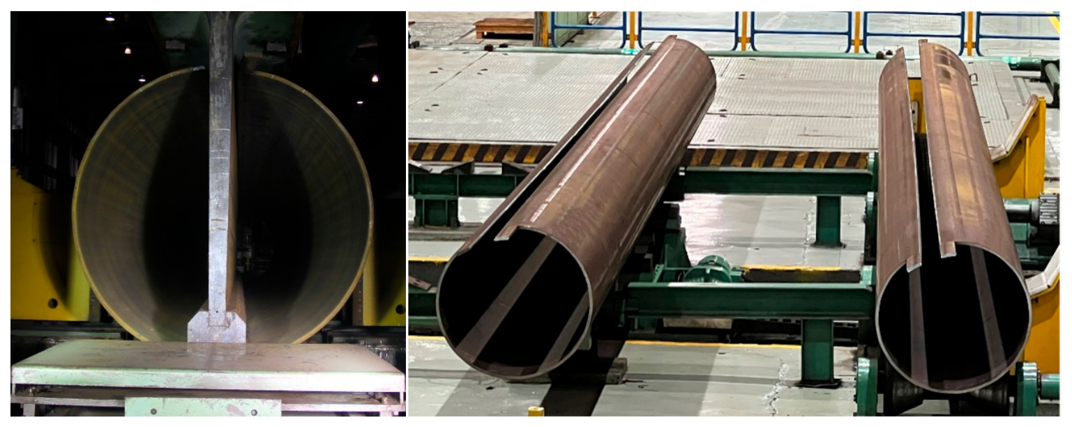
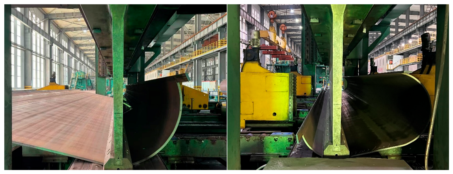
The JCO forming process of the X80M Φ1422 × 32.1 mm steel pipe is shown in Figure 21, and the formed pipe shell after completion is presented in Figure 22. The opening gap of the formed pipe body was measured at multiple points using a vernier caliper (measurement accuracy of 0.01 mm). The results show that the average opening gap of the 25-pass formed pipe shell is 118.85 ± 0.15 mm and that of the 29-pass formed pipe is 119.02 ± 0.12 mm. Both values are in close agreement with the design target (~119 mm), and the difference between them is less than 0.2%, indicating that both processes can effectively control the macroscopic opening dimension of the pipe body and meet the requirements of the subsequent tack-welding process for opening accuracy. The simulated opening gaps are 118.80 mm for the 25-pass process and 118.98 mm for the 29-pass process. The deviations between the experimental and simulated values are all less than 0.2%, and the trend is completely consistent (the 29-pass value is slightly larger than that of the 25-pass).
The out of roundness of the formed pipes was measured and calculated using a high-precision steel tape measure (measurement accuracy of 0.2 mm). The out of roundness of the pipe formed by the 25-pass process is 0.00769 and that of the 29-pass process is 0.00573. Compared with the simulated values of 0.00772 for the 25-pass process and 0.00571 for the 29-pass process, the deviations are less than 0.38%, confirming the validity of the simulation.
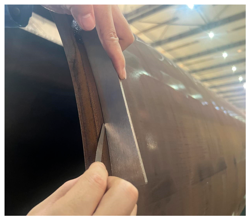
For the peaking index after forming, according to API Spec 5L, a standard template (with a template length equal to the smaller of 0.25 times the pipe outer diameter or 200 mm) was placed perpendicular to the pipe axis, and the maximum deviation from the ideal pipe contour was measured in conjunction with a feeler gauge [42,43], as shown in Figure 23. The measured peaking of the 25-pass formed pipe shell is 0.5 mm and that of the 29-pass formed pipe is 0.75 mm, both meeting the engineering requirement of not exceeding 1.0 mm. The peaking of the 25-pass process is superior to that of the 29-pass process.
The above validation demonstrates that the finite element model possesses high accuracy in predicting macroscopic dimensional deformation and that the simplifications adopted for the material constitutive model, contact friction, and boundary conditions are reasonable and effective.

5. Conclusions

To address the challenges of X80 steel grade extreme-specification Φ1422 × 32.1 mm steel pipes under conventional circular-arc die conditions—namely, the press load approaching the equipment limit, excessive forming passes, and difficulties in controlling forming accuracy—an innovative involute die with a dedicated profile was developed. This reduced the number of forming passes from the conventional limit of 29 to 25, and the improved process was validated through engineering application.
The innovative involute die was designed to increase the upper punch curvature radius from the conventional R450 mm to R475 mm, reduce the lower die opening from 340 mm to 320 mm, and extend the step length from 142 ± 5 mm to 165 ± 5 mm, thereby decreasing the forming passes from 29 to 25.
Numerical simulation analyses of the conventional 29-pass and the optimized 25-pass forming processes reveal that both processes yield consistent distributions of residual stress and plastic strain in the formed pipes, characterized by higher values at the surface layers and lower values in the core region, with the inner surface exhibiting higher stress and strain levels than the outer surface. The maximum residual stress (231.9 MPa) and maximum plastic strain (0.03859) of the 29-pass process are slightly higher than those of the 25-pass process (231.7 MPa and 0.03787, respectively), demonstrating the superiority of the 25-pass process.
In terms of geometric accuracy, the simulated model of the optimized 25-pass process shows a smaller opening gap (118.8 mm vs. 118.98 mm for the 29-pass process) and a smoother outer circumferential profile compared with the 29-pass process. This indicates that the 25-pass process offers superior control over forming accuracy. Moreover, the reduced opening gap effectively lowers the residual stress in the welded joint and reduces the susceptibility to stress corrosion cracking during service, while the smoother outer profile ensures better control of the peaking index of the formed pipe.

Author Contributions

Conceptualization, T.Z. and Z.H.; methodology, Z.H., T.Z. and H.L.; software, W.Z., H.L. and M.M.; validation, T.Z. and F.J.; formal analysis, Z.H. and T.Z.; investigation, T.Z. and M.M.; resources, F.J. and Z.H.; data curation, T.Z. and H.L.; writing—original draft preparation, T.Z. and W.Z.; writing—review and editing, Z.H. and M.M.; visualization, H.L. and T.Z.; supervision, Z.H.; project administration, T.Z.; funding acquisition, W.Z. All authors have read and agreed to the published version of the manuscript.

Funding

This study was funded by the National Natural Science Foundation of China (Grant Nos. 52501071).

Data Availability Statement

The original contributions presented in this study are included in the article. Further inquiries can be directed to the corresponding authors.

Acknowledgments

The authors gratefully acknowledge the support from Anhui University of Technology, Yanshan University, and Bohai Equipment Research Institute. We also thank all co-authors for their valuable contributions and support to this work.

Conflicts of Interest

Authors Tingting Zhang, Feng Ji, and Hongzhi Li were employed by the company CNPC Bohai Petroleum Equipment Manufacturing Co., Ltd. The remaining authors declare that the research was conducted in the absence of any commercial or financial relationships that could be construed as a potential conflict of interest.

References

  1. Liu, Y.; Han, T.; Yin, Z.-H. Research on mechanical properties of X80 line pipe girth welded joints produced by fully automatic gas metal arc welding. Welded Pipe Tube 2026, 49, 33–39. [Google Scholar] [CrossRef]
  2. Liu, Y.-Q.; Zhang, Z.-Y.; Wu, S.-S.; Ji, B.-L.; Zhang, H.; Liu, X.-B. Safety assessment on girth welds of large-diameter X80 pipelines in water network area. Oil Gas. Storage Transp. 2023, 42, 1128–1136. [Google Scholar] [CrossRef]
  3. Chen, X.; Feng, C.; Wang, B.; Wu, X.; An, Z.; Zhang, H.; Kong, T. Structural design and stress concentration analysis of girth weld joints of thickened pipe end. Welded Pipe Tube 2026, 49, 32–37. [Google Scholar] [CrossRef]
  4. Tang, J.; Wang, Z.; Dai, Z.; Liu, C.; Chen, Y.; Gong, W.; Huang, Y. Numerical simulation and performance study of four-wire submerged arc welding process for X80 heavy-wall steel linepipe. Steel Pipe 2026, 55, 23–29. [Google Scholar] [CrossRef]
  5. Peng, H.; Zhang, Z.; Wu, C.; Wang, J.; Su, X.; Zhao, Y.; Li, Z.; Xu, S. Study on the corrosion failure behavior of X80 pipeline steel in simulated soil solutions. J. Mater. Eng. Perform. 2026; in press. [CrossRef]
  6. Wang, C.-Y.; Liu, X.; Li, T.-Y.; Sun, M.-H.; Li, Z.-Y.; Zhang, N. Microstructure and fatigue properties of welded heat-affected zone of hot-rolled high-niobium X80 pipeline steel. Trans. Mater. Heat Treat. 2026, 47, 262–270. [Google Scholar] [CrossRef]
  7. Al-Zahrani, E.S.; Ogunlakin, N.; Toor, I.U.; Djukic, M.B. Hydrogen induced cracking of longitudinally submerged arc welded HSLA API 5L X65 carbon steel pipeline. Eng. Fail. Anal. 2024, 163, 108561. [Google Scholar] [CrossRef]
  8. França Freire, J.L.; Gomes, M.R.R.; Gomes, M.G. Handbook of Pipeline Engineering; Springer: Cham, Switzerland, 2024. [Google Scholar] [CrossRef]
  9. Thome, M.; Vochsen, J.; Gotsis, V. Calculation tool and closed loop control for the JCO® pipe forming process. Procedia Eng. 2017, 207, 1605–1610. [Google Scholar] [CrossRef]
  10. Wen, M.-J.; Zhang, X.; Shang, C.-Z. Research on single-pass forming width of JCOE longitudinal submerged arc welded pipe. Sci. Rep. 2025, 15, 35301. [Google Scholar] [CrossRef] [PubMed]
  11. Harianto, S.; Susilaputra, E.; Darto, P.; Fandika, A. Effect of squeeze-out and sizing ratio to the residual circumferential stress of HFW pipe. MATEC Web Conf. 2019, 269, 04005. [Google Scholar] [CrossRef]
  12. Kut, S.; Stachowicz, F.; Pasowicz, G. Springback prediction for pure moment bending of aluminum alloy square tube. Materials 2021, 14, 3814. [Google Scholar] [CrossRef] [PubMed]
  13. Zhao, J.; Li, J.; Qu, X.-Y.; Wang, G.; Sun, H.-L.; Ma, R. Study on intelligent control technology for forming steel pipe of pipeline with JCO process. Sci. China Technol. Sci. 2011, 54, 2754–2759. [Google Scholar] [CrossRef]
  14. Quang, V.D. The optimization of rotary bending die process: Criteria for the metal sheet angles and springback effects. Eng. Technol. Appl. Sci. Res. 2025, 15, 20553–20558. [Google Scholar] [CrossRef]
  15. Tovmasyan, M.A.; Samusev, S.V.; Sazonov, V.A. Study of the formation of large-diameter pipes with the use modern computer systems. Metallurgist 2016, 60, 179–185. [Google Scholar] [CrossRef]
  16. Xiong, Q.-R.; Li, Y.-H.; Shen, W.-Q.; Li, W.-W.; Li, X.; Zhang, Y.-H.; Xu, X.-F.; Jia, J.-J. Measurement and control of residual stress of high-grade and large-diameter welded pipe for oil and gas transportation. J. Mater. Eng. Perform. 2024, 33, 7479–7486. [Google Scholar] [CrossRef]
  17. Ren, P.; Fu, Y.; He, J.; Li, N.; Zhu, L.; Gu, Y.; Xiang, Y.; Jia, B. Effect of residual plastic strain on the fatigue failure mechanism and service life prediction of dented X80 pipelines. Materials 2026, 19, 967. [Google Scholar] [CrossRef] [PubMed]
  18. Adigamov, R.R.; Andreev, V.A.; Rogachev, S.O.; Fedotov, E.S.; Khadeev, G.E.; Yusupov, V.S. Effect of pipe forming on the mechanical properties of large diameter pipes. Russ. Metall. (Met.) 2023, 2023, 498–507. [Google Scholar] [CrossRef]
  19. Chen, P.-C.; Li, R.; Fu, K.; Zhao, X.-M. Research and method for in-line inspection technology of girth weld in long-distance oil and gas pipeline. J. Phys. Conf. Ser. 2021, 1986, 012052. [Google Scholar] [CrossRef]
  20. Tovmasyan, M.A.; Samusev, S.V.; Sidorova, T.Y.; Nguen, V.T. Study of changes in the shape of a pipe blank taking into account the peculiarities of contact interaction with a deforming tool during JCOE molding in the TESA 1420 line. Steel Transl. 2024, 53, 938–944. [Google Scholar] [CrossRef]
  21. Xu, L.-Z.; Qiao, G.-Y.; Ma, Y.-L.; Gu, Y.; Xu, K.; Chen, X.-W.; Xiao, F.-R. Numerical study of deformation inhomogeneity and its effect on mechanical properties of the heavy-wall offshore pipeline fabricated by different processes. Ocean. Eng. 2025, 323, 120656. [Google Scholar] [CrossRef]
  22. Liu, X.; Wang, Y.; Yang, Y.; Chen, J.; Chen, P.; Zhang, J.; Zhang, D. A novel machine learning-based strain capacity prediction model of high-grade pipeline girth welds using LightGBM. Materials 2026, 19, 726. [Google Scholar] [CrossRef] [PubMed]
  23. Singh, M.P.; Shukla, D.K.; Kumar, R.; Arora, K.S. The structural integrity of high-strength welded pipeline steels: A review. Int. J. Struct. Integr. 2020, 12, 172–199. [Google Scholar] [CrossRef]
  24. Li, Y.; Shuai, J.; Xu, K. Investigation on size tolerance of pore defect of girth weld pipe. PLoS ONE 2018, 13, e0191575. [Google Scholar] [CrossRef] [PubMed]
  25. Zhai, D.-Y.; Du, H.-J.; Wu, J.-P.; Jiang, J.-X.; Liu, S. Development of X80M hot-rolled steel plate for LSAW pipe. Iron Steel Vanadium Titan. 2021, 42, 131–138. [Google Scholar] [CrossRef]
  26. Chen, X.-W.; Wang, X.; Han, T.-L.; Zhang, Z.-X. Study on physical and chemical properties of X80 Φ1422 mm SAWL pipe of the China-Russian Eastern Natural Gas Pipeline. Welded Pipe Tube 2021, 44, 9–16. [Google Scholar] [CrossRef]
  27. Knapiński, M.; Dyja, H.; Kawałek, A.; Kwapisz, M.; Koczurkiewicz, B. Physical simulations of the controlled rolling process of plate X100 with accelerated cooling. Solid State Phenom. 2013, 199, 484–489. [Google Scholar] [CrossRef]
  28. Knapiński, M.J.; Koczurkiewicz, B.; Dyja, H.; Kawałek, A.; Kwapisz, M. The basic research of experimental steels for pipelines. Solid State Phenom. 2013, 199, 518–523. [Google Scholar] [CrossRef]
  29. Kim, N.-H.; Oh, C.-S.; Kim, Y.-J.; Kim, J.-S.; Jerng, D.W.; Budden, P.J. Limit loads and fracture mechanics parameters for thick-walled pipes. Int. J. Press. Vessel. Pip. 2011, 88, 403–414. [Google Scholar] [CrossRef]
  30. Dong, Z.-Q.; Xu, Z.-Z.; Wang, W.-K.; Bi, Z.-Y.; Zhang, J.-X. Numerical simulation and experimental confirmation of a bimetallic pipe forming process (JCO method). Materials 2020, 13, 3561. [Google Scholar] [CrossRef] [PubMed]
  31. Gao, Y.; Li, Q.; Fan, L.-F. Finite element analysis of JCO forming process for longitudinal seam submerged arc welded pipes. Int. J. Model. Identif. Control. 2010, 11, 239–249. [Google Scholar] [CrossRef]
  32. Chandel, J.D.; Singh, N.L. Formation of X-120 M line pipe through J-C-O-E technique. Engineering 2011, 3, 400–410. [Google Scholar] [CrossRef]
  33. Moço, R.F.; Cavalcante, F.G.; Donato, G.H.B. Effects of manufacturing plastic prestrains found on calendered and UOE pipes and pressure vessels on structural integrity assessments regarding fatigue crack growth and LBB. Procedia Struct. Integr. 2018, 13, 1915–1923. [Google Scholar] [CrossRef]
  34. Jiao, J.S.; Lu, C.; Lee, C.S.; Bae, J.H.; Barbaro, F. Introduction of the delta concept for characterising pipe yield strength. Int. J. Mater. Form. 2020, 13, 623–637. [Google Scholar] [CrossRef]
  35. Luo, J.-T.; Xue, Y.-H.; Chen, K.; Shang, Y.-P.; Zhang, C.-X. Integrated simulation and experimental test of the residual stress field for large-sized straight welded pipe processed with JCOE technology. Int. J. Steel Struct. 2017, 17, 265–272. [Google Scholar] [CrossRef]
  36. Peng, N.-Q.; Shi, S.-H.; Luo, D.; Xiong, X.-J.; Li, Z.-P. Effect of strain aging on tensile properties of X80 large-diameter pipeline steel. Mater. Mech. Eng. 2018, 42, 42–45. [Google Scholar] [CrossRef]
  37. Wei, H.-T.; Tang, H.; Xing, B.-H.; Shang, J.; Qiu, S.-Y.; Hua, Z.-L.; Gu, C.-H. Research on the fracture toughness of pipeline steel X80 in a hydrogen environment. Eng. Fail. Anal. 2025, 180, 109917. [Google Scholar] [CrossRef]
  38. Wang, Z.; Cui, R.-X.; Zhang, Q.-C.; Song, W.-C. Study on fracture toughness and defect tolerance of X80 pipeline steel in simulated natural gas environment containing 2% H2. Mech. Eng. 2023, 45, 296–304. [Google Scholar] [CrossRef]
  39. Antoniou, K.; Chatzopoulou, G.; Karamanos, S.A.; Tazedakis, A.; Palagas, C.; Dourdounis, E. Numerical simulation of JCO-E pipe manufacturing process and its effect on the external pressure capacity of the pipe. J. Offshore Mech. Arct. Eng. 2018, 140, 061701. [Google Scholar] [CrossRef]
  40. Xie, P.; Chang, J.-T. 3D dynamic analysis of JCO manufacturing process of large-diameter submarine pipelines. J. Ship Mech. 2022, 26, 235–249. [Google Scholar] [CrossRef]
  41. Shang, Y.-P. Integrated Simulation and Analysis of the Residual Stress Field for Large-Sized Straight Welded Pipe Processing with JCOE Technology. Master’s Thesis, Yanshan University, Qinhuangdao, China, 2014. [Google Scholar]
  42. Ma, Q.-R.; Huo, C.-Y. Comparison and analysis on specification of X80 line pipe for 2nd West-East Gas Transmission Pipeline Project. In Proceedings of the 8th International Pipeline Conference, Calgary, AB, Canada, 27 September–1 October 2010; American Society of Mechanical Engineers: New York, NY, USA, 2010; pp. 699–705. [Google Scholar] [CrossRef]
  43. Zhang, W.-W.; Li, H.; Chi, Q.; Zhao, X.-W.; Huo, C.-Y.; Qi, L.-H.; Li, Y.-H.; Yang, K. Technical specifications for X80 OD 1422 mm line pipes and corresponding products. Nat. Gas. Ind. B 2016, 3, 485–492. [Google Scholar] [CrossRef]
Figure 1. Metallographic microstructure of X80M 32.1 mm steel plate. (a) Near-surface layer, (b) 1/4 T, and (c) 1/2 T (T-wallthickness).
Metals 16 00845 g001
Figure 2. Forming die scheme of conventional circular arc lower die (R450/V340).
Metals 16 00845 g002
Figure 3. Schematic diagram of involute lower die forming mold (R475/V320).
Metals 16 00845 g003
Figure 4. Three-dimensional finite element model of JCO forming. 1—Upper die; 2—lower die base; 3—steel plate; 4—forming support frame.
Metals 16 00845 g004
Figure 5. Transverse and longitudinal tensile stress–strain curves of the tested 32.1 mm thick X80 steel plate.
Metals 16 00845 g005
Figure 6. Stress nephogram during 29-pass pressing process.
Metals 16 00845 g006
Figure 7. Residual stress nephogram after 29-pass pressing.
Metals 16 00845 g007
Figure 8. Residual stress nephogram of the middle cross-section of the steel plate after 29-pass pressing. (a) Entire cross-section distribution, and (b) Partial enlargement.
Metals 16 00845 g008
Figure 9. Radial distribution curve of residual stress at the longitudinal middle cross-section of steel plate after 29-pass pressing (from inner wall to outer wall).
Metals 16 00845 g009
Figure 10. Overall plastic strain distribution of 29-pass forming.
Metals 16 00845 g010
Figure 11. Plastic strain distribution at the longitudinal middle cross-section after 29-pass forming.
Metals 16 00845 g011
Figure 12. Stress nephogram during 25-pass pressing.
Metals 16 00845 g012
Figure 13. Residual stress nephogram after 25-pass pressing.
Metals 16 00845 g013
Figure 14. Residual stress nephogram at the middle cross-section of steel plate after 25-pass pressing. (a) Entire cross-section distribution, and (b) Partial enlargement.
Metals 16 00845 g014
Figure 15. Radial distribution curve of residual stress at the longitudinal middle cross-section for 25-pass forming (from inner wall to outer wall).
Metals 16 00845 g015
Figure 16. Overall plastic strain distribution of 25-pass forming.
Metals 16 00845 g016
Figure 17. Cross-sectional plastic strain distribution at the longitudinal middle position after 25-pass forming.
Metals 16 00845 g017
Figure 18. Comparison curve of residual stress between two forming processes.
Metals 16 00845 g018
Figure 19. Forming results after pressing: (a) 29 passes and (b) 25 passes.
Metals 16 00845 g019
Figure 20. Outer circular contour lines of extracted models after forming by two processes. (a) Simulated models from the two forming processes and (b) partially enlarged view of the models.
Metals 16 00845 g020
Figure 21. JCO forming process of X80M steel pipe.
Metals 16 00845 g021
Figure 22. Formed pipe blank.
Metals 16 00845 g022
Figure 23. Measurement of peaking of the formed pipe shell.
Metals 16 00845 g023
Table 1. Chemical composition (wt.%) of X80-grade, 32.1 mm thick steel plate.
Chemical ElementCMnSiMoNiCrCuVNbTiBV + Nb + TiCEpcm
0.0441.700.200.1430.1820.2240.1440.0020.0580.0140.00010.0740.17
Industry standard
DEC-NGP-S-PL-003-2020-1
≤0.07≤1.85≤0.350.08~0.350.10~0.30≤0.30≤0.30≤0.060.03~0.10≤0.025≤0.001≤0.15≤0.23
Table 2. Tensile properties of the test material.
Tensile PropertiesYield Strength Rt0.5/MPaTensile Strength Rm/MPaYield-to-Tensile Ratio Rt0.5/RmElongation A%
5566910.8025
Industry standard
DEC-NGP-S-PL-001-2020-1
555~690625~765≤0.93≥16
Table 3. Forming process parameters.
Upper Die Curvature mmLower Die Spacing mmStep Length mmNumber of Pressing PassesEdge Length mm
R450340142 ± 529180
Pressing Depth
mm
Crowning Compensation
mm
Forming Force
kN
200 ± 50~2.06000 ± 400
Table 4. Specific parameters of the improved forming process.
Upper Die Curvature mmLower Die Spacing mmPressing Step Length mmNumber of Pressing PassesEdge Length mm
R475320165 ± 525180
Pressing Depth
mm
Crowning Compensation
mm
Forming Force
kN
216 ± 51.0~2.06000 ± 400
Table 5. Boundary conditions and material property parameters of the simulation.
Parameter CategoryParameter ItemSpecific Value/DescriptionRemarks
Geometric and Boundary SimplificationSimplification of support mechanismsDiscrete rigid planeSimplified based on Saint-Venant’s principle; structural details have negligible influence on stress and strain distribution, thus reducing computational cost
Simplification of upper and lower dies3D discrete rigid body, modeled at 1:1 full scaleBased on the small deformation assumption; the elastic deformation of dies is far smaller than that of the steel plate and can be neglected
Initial Assembly Boundary ConditionsPosition of forming support frame and lower dieTheir highest points lie on the same horizontal planeTo ensure the initial horizontal placement of the steel plate and avoid uneven stress distribution
Initial positioning of the steel plateIts lower surface is in direct contact with the upper surface of the support plate, with the left end face 180 mm from the central axis of the lower pressing die/
Global coordinate systemX-axis: along the width of the steel plate; Y-axis: perpendicular to the steel plate plane and pointing upward; Z-axis: along the length of the steel plateTo unify the positioning datum of all components
Displacement Constraint ConditionsLeft and right support frames and lower pressing dieFully fixed constraint (restricting translational degrees of freedom (DOFs) in X/Y/Z directions and all rotational DOFs)To simulate the fixed state of the die in actual production and provide a stable mechanical boundary
Kinematic constraint of upper pressing dieOnly the translational DOF in the Y direction is released; it moves downward by the preset distance Y1 during pressing and upward by the preset distance Y2 during the return strokeThe motion trajectory and velocity are set according to actual production process parameters
Constraint on the central axis of the steel plateOnly the DOF in the Y direction is released, while displacements in all other directions are constrainedTo ensure the stability of the steel plate during the pressing process
Feeding constraint of the steel plateDisplacement in the X direction is constrained during the pressing stage (ux = 0); after each single pressing pass, the coordinates are updated along the X-axis by the preset step length X1To simulate the intermittent step-by-step feeding of the JCO process
Load Boundary ConditionsGravity loadGravitational acceleration of 9.81 m/s2 is imposed on the steel plate in the Y directionTo fully account for the mechanical influence of gravity during the pressing process
Contact Boundary ConditionsContact algorithmPenalty contact method/
Friction coefficient0.08/
Normal contact typeHard contact/
Analysis Step SettingsAnalysis step typeDynamic explicit analysis step (ABAQUS/Explicit)The multibody dynamics analysis step is adopted to fully reproduce the multi-pass JCO forming process
Material Constitutive Boundary ConditionsMaterial modelIsotropic elastoplastic material modelThe yield strength difference between the transverse and longitudinal directions of the steel plate is only 11 MPa, which validates the isotropic approximation
Young’s modulus E206,000 MPa/
Poisson’s ratio0.33/
Mass density7.83 g/cm3/
Plastic parametersThe yield stress–plastic strain curve is obtained from laboratory tensile testsThe parameters adopt the actual mechanical properties of the base metal
Disclaimer/Publisher’s Note: The statements, opinions and data contained in all publications are solely those of the individual author(s) and contributor(s) and not of MDPI and/or the editor(s). MDPI and/or the editor(s) disclaim responsibility for any injury to people or property resulting from any ideas, methods, instructions or products referred to in the content.