Article

Numerical Study of Steel Ball Rolling Using Spiral Discs

Mechanical Faculty, Lublin University of Technology, 36 Nadbystrzycka Str., 20-618 Lublin, Poland
Metals 2026, 16(6), 593; https://doi.org/10.3390/met16060593 (registering DOI)
Submission received: 4 May 2026 / Revised: 26 May 2026 / Accepted: 26 May 2026 / Published: 29 May 2026
(This article belongs to the Special Issue Advanced Rolling Technologies of Steels and Alloys)

Abstract

This study proposes a new method for rolling steel balls using spiral discs. The aim of the study was to investigate whether the proposed method could be used to produce balls with a diameter of 63 mm, as well as to determine the effect of tool geometry and the number of billets on process stability, force, and the energy parameters of the rolling process. Numerical simulations were performed using Forge® NxT v.4.0. The billet for rolling was made of C60 steel and preheated to 1050 °C. The following cases of ball rolling were simulated: Ball rolling using flat discs with single, double, and triple spiral impressions made on their working surface, and ball rolling using tapered discs for two different configurations of the working system. The rolling process was examined in terms of ball shape, internal defect formation, temperature distribution, as well as force and energy parameters. The results showed that the rolling process conducted using tapered discs and by flat discs with single and double impressions produced correctly shaped balls without internal cracks. It was also found that discs with double impressions were more advantageous than the single-impression ones in terms of energy consumption, while the use of discs with triple spiral impressions led to higher tool load and reduced product quality despite the high efficiency of these discs. The system comprising one disc with an external conical working surface and one disc with an internal conical working surface yielded the best results with the lowest energy consumption and power demand. The findings of this study demonstrate that ball rolling using spiral discs is a promising alternative to standard skew rolling methods.

1. Introduction

Steel balls are widely used as grinding media in ball mills for grinding metal ores, coal, materials used in the production of cement and ceramics, spent molding sands, etc. The annual demand for such balls amounts to hundreds of thousands of tons; therefore, there is a constant search for new ways of increasing the production capacity for grinding balls.
Currently, the primary method for producing steel balls is skew rolling with helical rolls. Although this process is not widely known, it has attracted the attention of a number of researchers in recent years.
The primary challenge in this ball rolling process is to design a helical impression that will ensure the formation of balls without internal or external defects. To date, several methods for calibrating rolls have been developed, which are based on the principle of maintaining a constant material volume in the roll pass over the entire forming length (this volume being equal to the volume of a formed ball) [1,2]. Two dominant approaches to roll design can be distinguished in this respect: one assumes a constant flange width [3,4], while the other uses a variable flange width [5,6]. The first approach is dedicated to the hot rolling of larger-sized balls, while the other is used for the cold or warm rolling of balls for rolling bearings. In this context, it is also worth mentioning a novel design of helical-wedge tools, which was developed at the Lublin University of Technology [7,8]. Designed according to the aforementioned methods, flanges form small-diameter bridges connecting adjacent balls, which are then torn apart or cut off by special cutters in the final stage of rolling [9].
To increase the efficiency of the ball rolling processes, tools with multiple impressions are designed. The literature describes solutions for rolls with two [10,11], three [12,13], and four impressions [14,15]. The use of such tools enhances process efficiency by a factor equal to the number of impressions made on the tool’s working surface. However, it should be noted that the use of multi-impression tools entails higher tool inclination angles which in turn has a negative impact on the accuracy of formed balls.
The development of numerical methods has provided important insights into skew rolling. Early studies on this complex forming process [16,17] were limited to the initial stage of forming and did not make a significant contribution to the state of the art. In 2013, Pater et al. [18] used Simufact to perform a comprehensive numerical analysis of a hot helical rolling process for balls (including by rolls with multiple helical impressions). The same simulation software was later used to investigate the impact of forming zone length on rolling process stability [19], the cold rolling of balls for rolling bearings [20], and predicting the microstructure of balls produced by cold [21] and hot rolling [22]. Deform-3D is another software for analyzing the helical rolling of balls, which has been used to simulate, among others, the warm rolling of balls for rolling bearings [23,24] and void closure in rolled balls [25]. The above-mentioned programs did not however make it possible to simulate ball separation. This became possible with the development of the Forge program, which allowed for determining the impact of helical impression calibration methods on the overall stability of the ball rolling processes. While discussing the use of numerical methods in the analyses of forming balls by helical rolling, it is worth mentioning a study by Beygelzimer et al. [26] which presented formulas for calculating force and energy parameters in this process.
Other studies on ball rolling investigated aspects such as ball quality [27,28], the thermal treatment of balls [29,30] and rolls [31], ball microstructure [32], as well as the operation of rolls and rolling mills [33,34].
Despite significant advances in research on the skew rolling of balls, previous studies primarily dealt with standard systems based on the use of helical rolls. No study to date has undertaken a more comprehensive analysis of alternative methods for forming balls, e.g., by using spiral discs as tools. This solution appears particularly interesting because it allows for the use of both tools with multiple impressions and a higher number of billets, leading to a significant increase in process efficiency. At the same time, however, tool geometry modifications can affect not only the production efficiency of rolling but also the quality of rolled balls, as well as forces and torques in the working system.
Currently, hot-rolled grinding balls are typically manufactured within a diameter range of 20–120 mm. In the present study, balls with a diameter of 63 mm were selected because this size represents an intermediate value within the industrial range and is commonly used in grinding processes.
The objective of this study was twofold: to investigate numerically whether steel balls of 63 mm in diameter could be rolled using spiral discs and to determine the impact of tool geometry and the number of billets on rolling process stability, product quality, and force and energy parameters. The present study was not intended as a formal optimization of the rolling process but rather as a comparative analysis of selected technological variants of ball rolling with spiral discs. The following cases of ball rolling were simulated: Ball rolling using flat discs with single, double, and triple impressions, as well as ball rolling with the use of tapered discs for two configurations of the working system. Produced balls were examined for their shape and the presence of internal defects. In addition, forces, torques, energy consumption, and power demand were determined. Due to the high experimental costs, the study was limited to performing thermo-mechanical simulations in Forge® NxT v.4.0.

2. Numerical Model of Ball Rolling Process and the Scope of Calculations

Numerical simulations involved rolling balls with a diameter of 63 mm; when manufactured for use in grinding mills, such balls are produced within a dimensional tolerance of ±3 mm. The balls were assumed to be made of C60 steel, the material model of which is described by the following equation
σ F = 1706.99 e 0.0028 T ε 0.19371 e 0.07421 / ε ε ˙ 0.1467 ,
where σF—flow stress, ε—effective strain, ε ˙ —strain rate, T—temperature.
The material model of C60 steel was taken from the material database of Forge® NxT v.4.0. According to the database information, the model is valid for temperatures ranging from 643 to 1250 °C, strain rates from 0.01 to 500 s−1, and effective strains from 0.04 to 1.5, which covers the main thermomechanical conditions occurring in the analyzed rolling process. Since the billet was assumed to be preheated to 1050 °C and its temperature during rolling remained within the high-temperature austenitic range, phase transformations were not considered in the present model.
Cylindrical bars with a diameter of 60.9 mm and preheated to 1050 °C were used as a billet for rolling. The working tools were two discs rotating in opposite directions at a speed of 60 rev/min. In addition, auxiliary tools were used, such as a guide, pusher and ball container. All tools were assumed to be perfectly rigid bodies, and their temperature maintained constant at 250 °C. The tools were assumed to be made of hot-work tool steel X37CrMoV5-1 (1.2343), commonly applied in hot metal forming processes.
During rolling, the workpiece is pulled in between the discs and rotated as a result of the action of friction forces on the workpiece–tool contact surface. Given its nature, the ball rolling process in question was described by a constant friction model, according to which
τ = m   k ,
where τ—shear stress on contact surface, m—friction factor (set equal to m = 0.99 for discs and m = 0.6 for other tools), k—yield stress at pure shear k = σ F / 3 .
The calculations took into account the phenomenon of heat transfer between the workpiece, environment, and tools, which depended on the temperatures of the workpiece, environment, and tools, as well as their heat transfer coefficients. The heat transfer coefficient between the tool and the workpiece was set to 10,000 W/m2K, while that between the workpiece and the environment was 200 W/m2K. The adopted heat transfer coefficient corresponds to the thermal interaction between steel tools and the steel billet and has been successfully applied in previous numerical analyses of hot rolling processes.
It was assumed that balls would be separated from the rest of the workpiece when the damage function f would reach a critical value of C. The function f was calculated with the normalized Cockcroft–Latham criterion, according to which
f = σ 1 σ i d ε ,
where σ1—maximum principal stress, σi—reduced stress, ε—effective strain. The critical damage value C = 3.0 was adopted based on the results reported in [7], where numerical and experimental investigations of the hot skew rolling of balls made of the same steel grade were performed under comparable thermomechanical conditions. The comparison of numerical predictions with experimental results confirmed the applicability of this value for predicting internal defects in rolled balls.
A numerical analysis was performed using Forge® NxT v.4.0. This program had been previously used to simulate processes such as cross-wedge rolling [35], skew rolling [36], and ring rolling [37,38]. The numerical results showed a very high agreement with the results of validation experiments.
This study is limited to determining whether balls formed by the proposed method have the required shape and are free from internal defects (cracks). In the present study, ball quality was evaluated based on the obtained shape of the balls, dimensional accuracy relative to the assumed industrial tolerance of ±3 mm for 63 mm grinding balls, and the absence of internal defects predicted using the Cockcroft–Latham damage criterion. Special focus is put on the force and energy parameters in the rolling process. It should also be noted that the prediction of internal defects was based exclusively on FEM simulations using the Cockcroft–Latham criterion and still requires experimental verification for the proposed rolling process with spiral discs.

3. Results

3.1. Ball Rolling Using Flat Discs

Flat-disc rolling is conducted using two identical discs that are set coaxially, facing each other with their working surfaces (i.e., spiral impressions). The billet for rolling is fed in between the discs by a pusher. There is no separate mechanical gripping system in this process. The billet is pushed between the spiral discs and is then gradually drawn into the forming zone by friction forces acting at the tool–workpiece contact surface. During rolling, the billet position is additionally stabilized by guide elements. Possible slippage between the workpiece and the tools was included in the FEM model through the adopted friction conditions. The stability of billet gripping was assessed qualitatively based on the FEM simulation results including stable material flow and the absence of contact loss during forming. A quantitative analysis of gripping stability and slip limits requires further numerical and experimental investigations. The pusher is only used during the initial phase of the rolling process to ensure proper engagement of the workpiece by the prongs separating the spiral impressions. The circumferential position of the workpiece is controlled by a tubular guide. This rolling process can be performed using one or more billets, their number depending on the number of spiral impressions. To give an example, Figure 1 shows the geometric model of a ball rolling process conducted using flat discs with double spiral impressions, using two billets spaced by 180°.
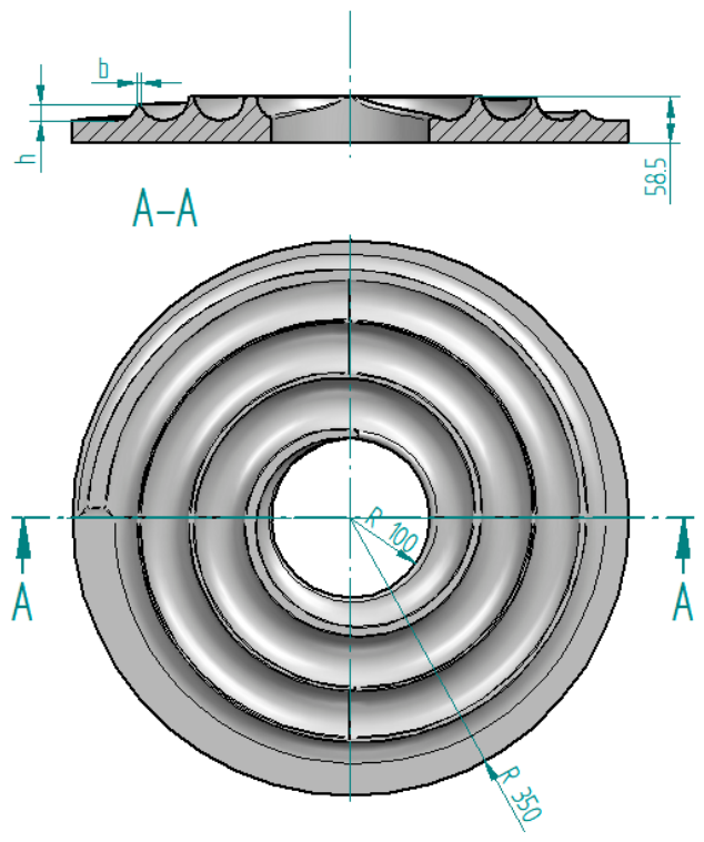
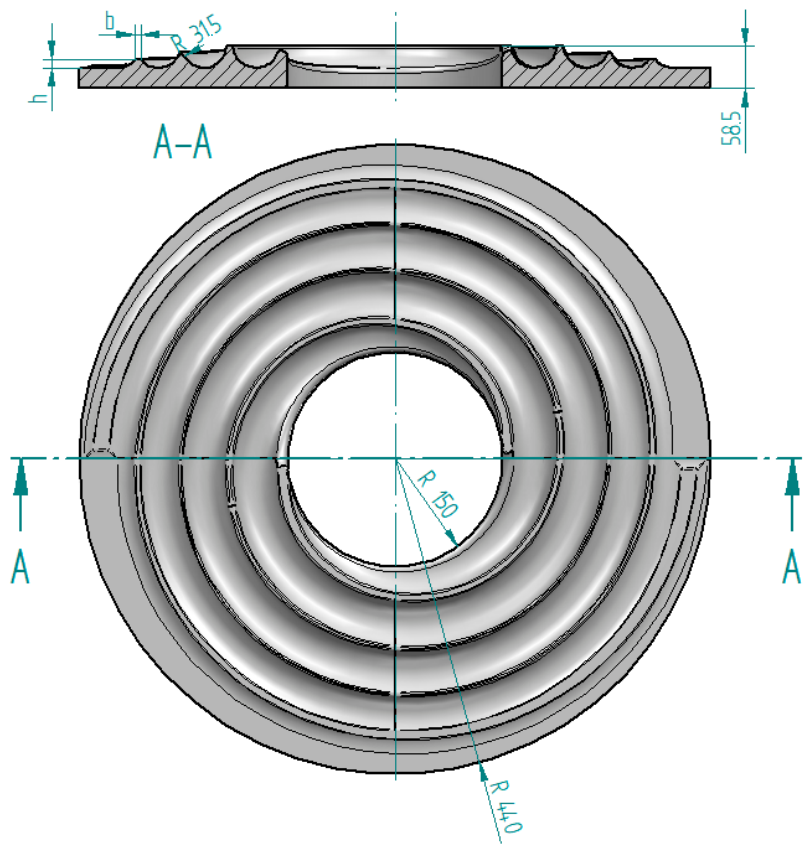
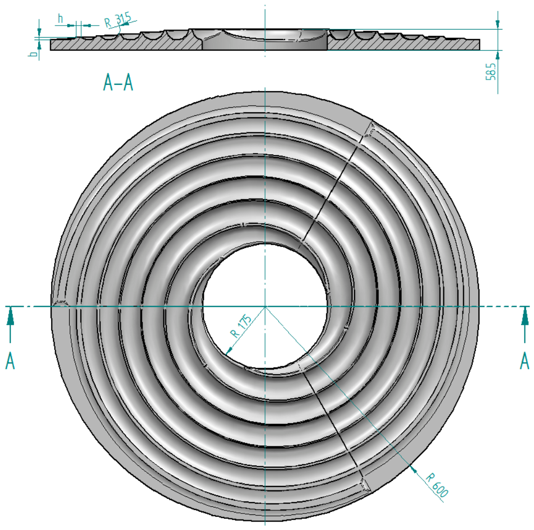
Spiral-impression discs are the key tools in this ball rolling process. Figure 2, Figure 3 and Figure 4 show the discs used in the study: with single, double, and triple spiral impressions, respectively. The use of a higher number of spiral impressions results, on the one hand, in higher rolling efficiency and, on the other, in larger tool dimensions, which in turn entails a higher torque.
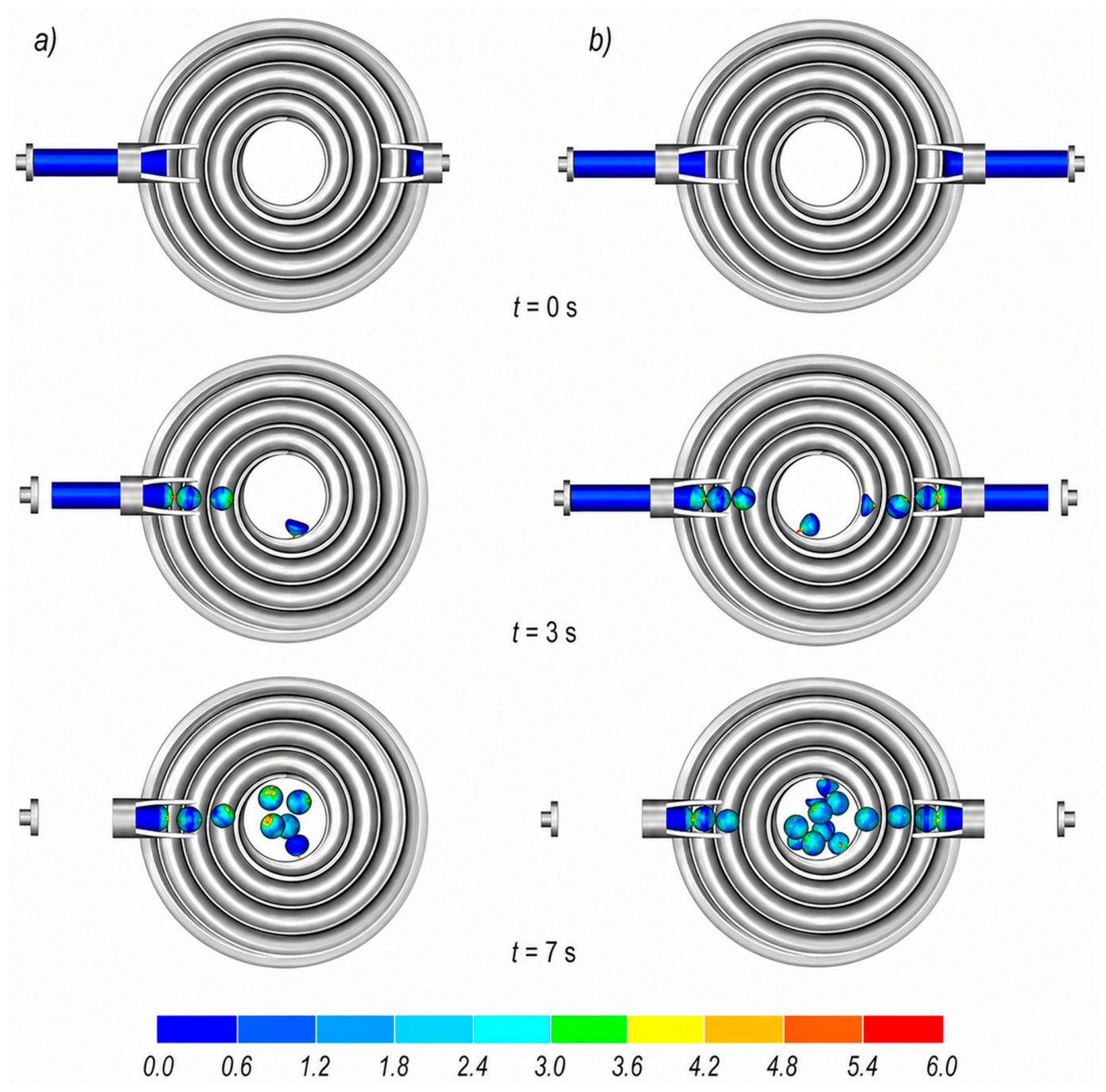
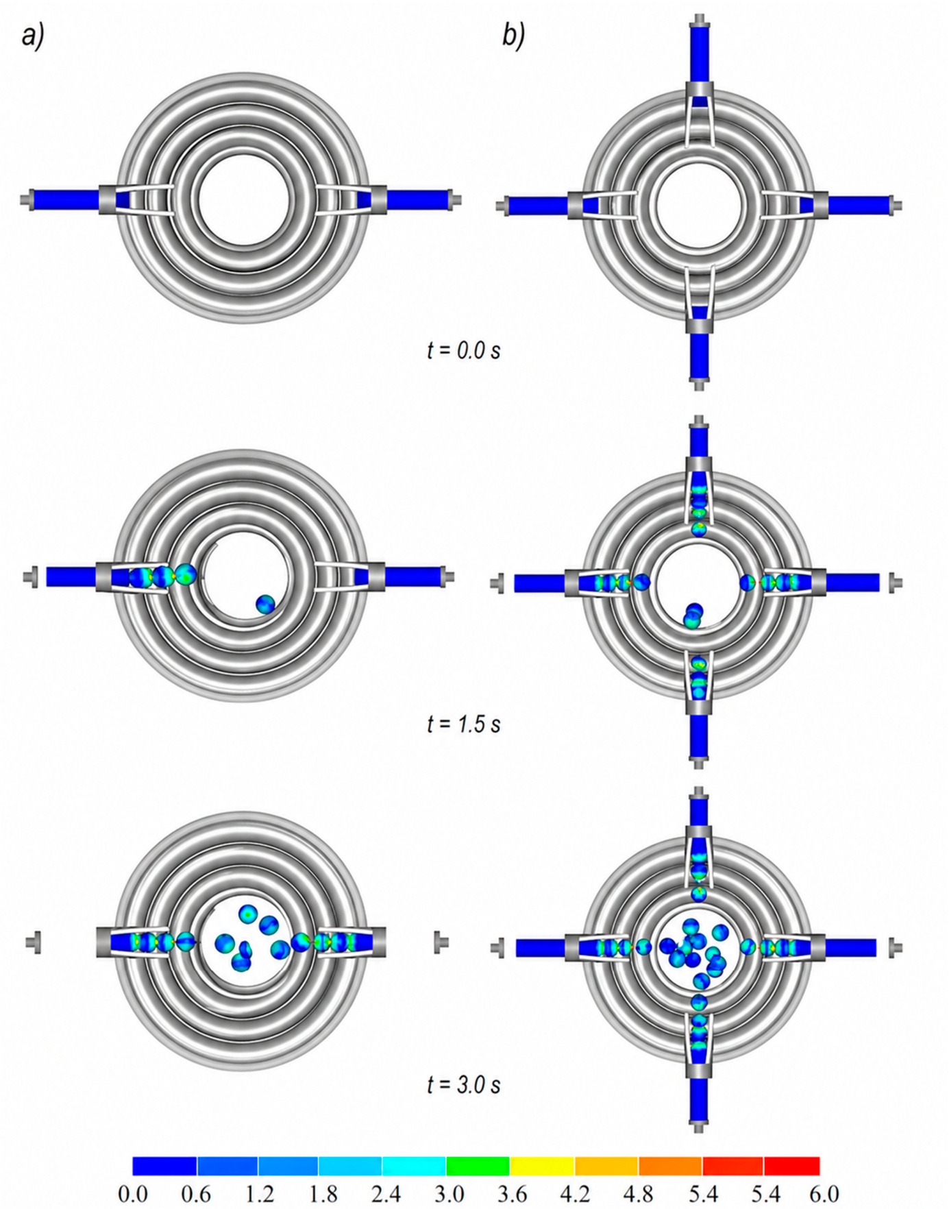
Figure 5 shows two cases of ball rolling with single-impression discs. In the first case, one billet is used, whereas in the second case two billets are used. In both cases, the formation of an individual ball extends over three revolutions of the discs. However, once the rolling process reaches a steady state, one ball is produced from each billet during each revolution of the discs. After separation from the workpiece, the balls fall through the central hole in the disc into the container. All balls have the correct shape and are free from internal defects, such as cracks. Therefore, the theoretical production capacity of this rolling process is 60 and 120 balls per minute for one and two billets, respectively. These values represent the theoretical maximum productivity determined from the number of billets, the number of spiral impressions, and the rotational speed of the discs without considering practical industrial limitations.
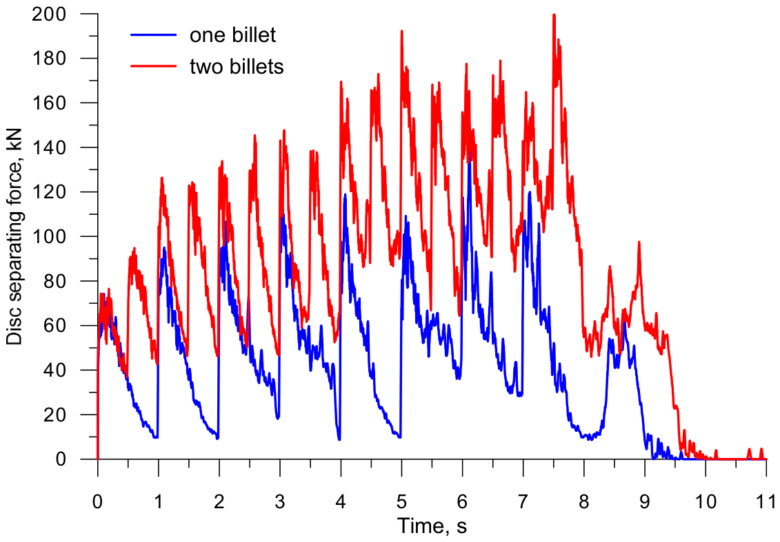
Figure 6 shows the distributions of the separating force acting on the tool during a ball rolling process conducted with single-impression flat discs. Understanding this force is important for selecting the appropriate rolling mill design. The discs should not undergo excessive deformation during rolling, as this would result in the lower accuracy of produced balls. As can be seen in Figure 6, the force has an oscillatory behavior pattern, which results from the cyclic cutting of the impression-separating prongs into the workpiece. The maximum force was 135 kN in rolling from one billet and 198 kN in rolling from two billets. It is also important to note that when two billets are used, two component forces act on opposite sides of the discs. This situation is more advantageous than having a load only on one side of the discs, which is the case in single-billet rolling.
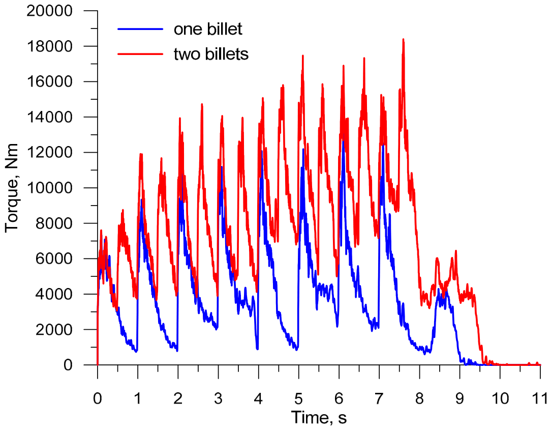
The energy consumption of the ball rolling processes under study can be determined based on the torque distributions shown in Figure 7. Similarly to the force, this parameter exhibits an oscillatory behavior pattern. The mean torque at the steady-state stage of the ball rolling process (i.e., for t = 3 ÷ 7 s) is 4818.8 Nm in rolling from one billet and 10,035.7 Nm in rolling from two billets. Considering the above values and the disc speed of 60 rev/min, it is possible to calculate the energy required to form one ball, which is 60.52 kJ in single-billet rolling and 63.02 kJ in double-billet rolling. Using the data in Figure 7, one can also determine the maximum torque, which is 13,790.7 Nm and 17,475.3 Nm in rolling using one and two billets, respectively. Based on this, one can calculate the minimum drive power of a single disc, which is 86.6 kW and 109.75 kW, respectively. Given the oscillating load on the discs, the drive power calculated in this way can naturally be reduced by using a flywheel.
When double-impression discs are used, rolling can be performed using one, two, or four billets at the same time. Two balls are formed from each billet during one revolution of these discs. This means that the theoretical production capacity of this rolling process will be 120 pcs/min, 240 pcs/min and as high as 480 pcs/min, respectively. Figure 8 illustrates a rolling process conducted with double-impression flat discs, using two and four billets. In these cases of the rolling process, a single ball is formed during two revolutions of the discs. The results show that the produced balls meet the requirements regarding their shape and lack of internal cracks.
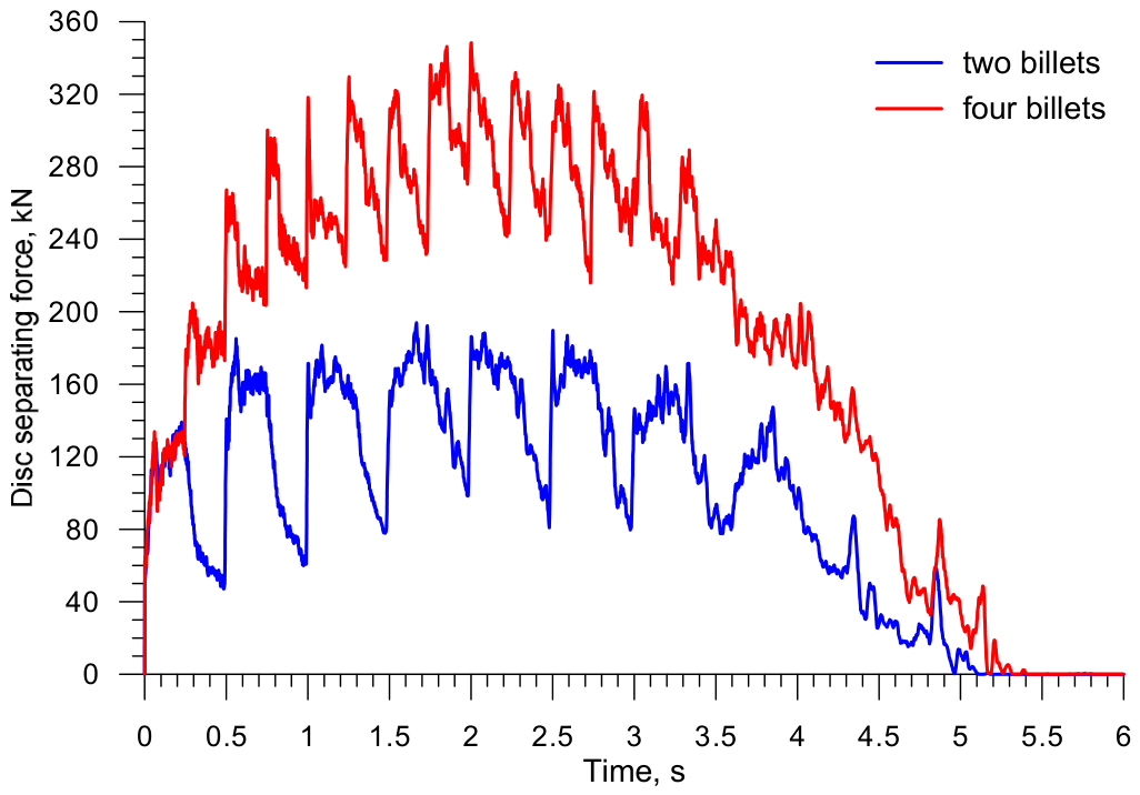
Figure 9 shows the separating force in a rolling process conducted with double-impression discs, using two and four billets. As in the case of single-impression discs, the force exhibits an oscillatory pattern, but with a smaller amplitude. The maximum force is 196 kN (for two billets) and 348 kN (for four billets). It can therefore be concluded that the loads acting on single- and double-impression discs are identical for the same number of billets. It should also be noted that when ball rolling is conducted from four billets, the resultant separating force consists of four unit forces, distributed at 90° intervals around the circumference of the discs, which results in a more uniform load distribution.
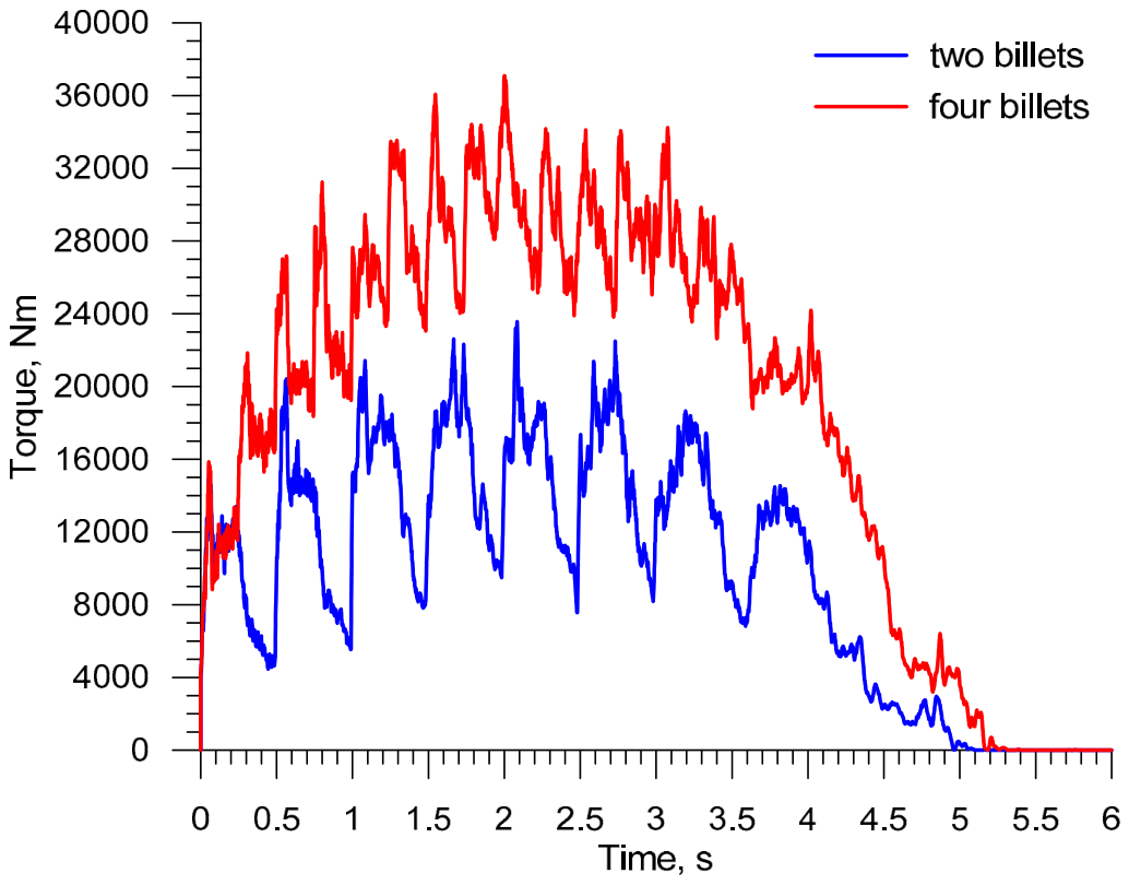
Interesting observations can be made by analyzing the torque in a rolling process conducted with two double-impression discs, which is shown in Figure 10. The mean torque calculated for a time interval of t = 2 ÷ 3 s is 15,394.3 Nm (for two billets) and 29,233.7 Nm (for four billets). This means that the energy required to form a single ball is 48.34 kJ and 45.90 kJ in rolling from two and four billets, respectively. Consequently, ball rolling conducted with double-impression discs is less energy consuming than that based on the use of single-impression discs. The reduction in specific energy consumption results mainly from the shorter forming path. In single-impression discs, one ball is formed during slightly more than three disc revolutions, whereas in double-impression discs ball formation is completed within approximately two revolutions. As a result, the duration of frictional interaction is shorter, the material cooling during forming is reduced, and the plastic deformation work required to form one ball decreases. However, although the specific energy consumption decreases, the total torque and required drive power increase because more balls are formed simultaneously. The minimum power per disc, calculated based on the maximum torque values of 23,569.0 Nm and 37,103.4 Nm, is 148 kW and 233 kW for rolling from two and four billets, respectively.
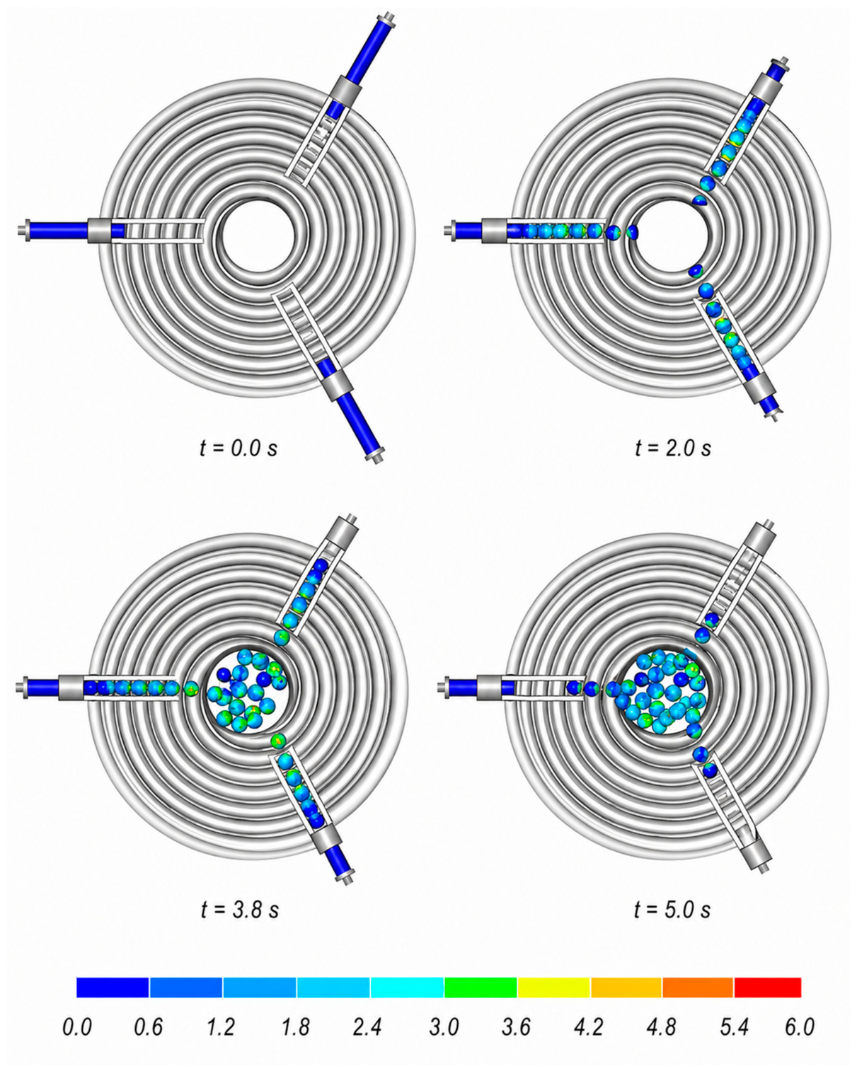
When ball rolling is conducted with triple-impression discs, one, three (Figure 11), or six billets can be simultaneously fed into the forming zone. During a single revolution of the discs, three balls are formed from each billet, which means that the theoretical production capacity of this rolling process is 180 pcs/min (from one billet), 540 pcs/min (from three billets), and as many as 1080 pcs/min (from six billets). However, due to the large helix pitch, balls formed by this rolling method may be distorted, which will render them unsuitable for use in ball mills. Moreover, in this ball rolling process, the discs are subjected to high loads.
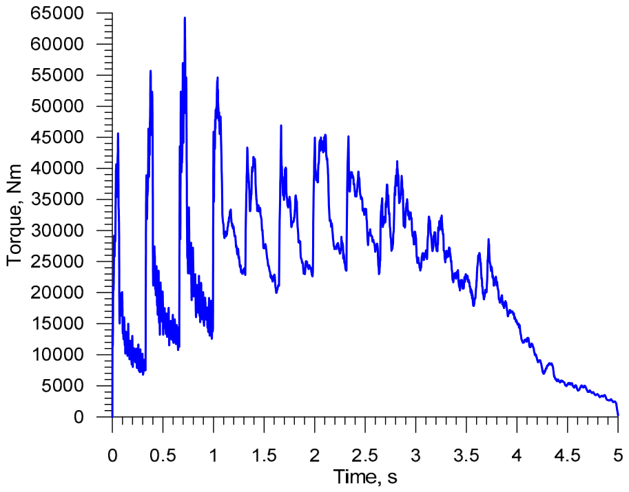
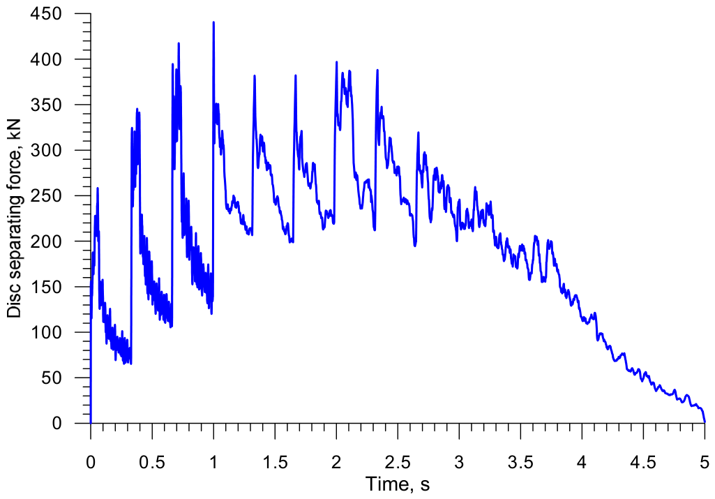
The maximum force (in rolling from three billets) can reach a value of 440 kN (Figure 12). This is approximately 50% higher than in rolling with double-impression discs from four billets. This means that a machine for this ball rolling process will be much heavier. The larger size of the discs also entails a higher torque (Figure 13), which for the steady-state rolling process (t = 2–3 s) would reach a mean value of 33,363.9 Nm and a maximum value of 45,429 Nm. Based on these data, the drive power of a single disc would be 285.3 kW, while the energy required to form a single ball would be 45.56 kJ (these parameters apply to ball rolling using three billets).
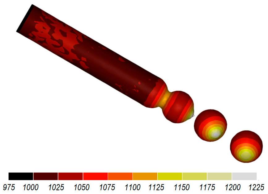
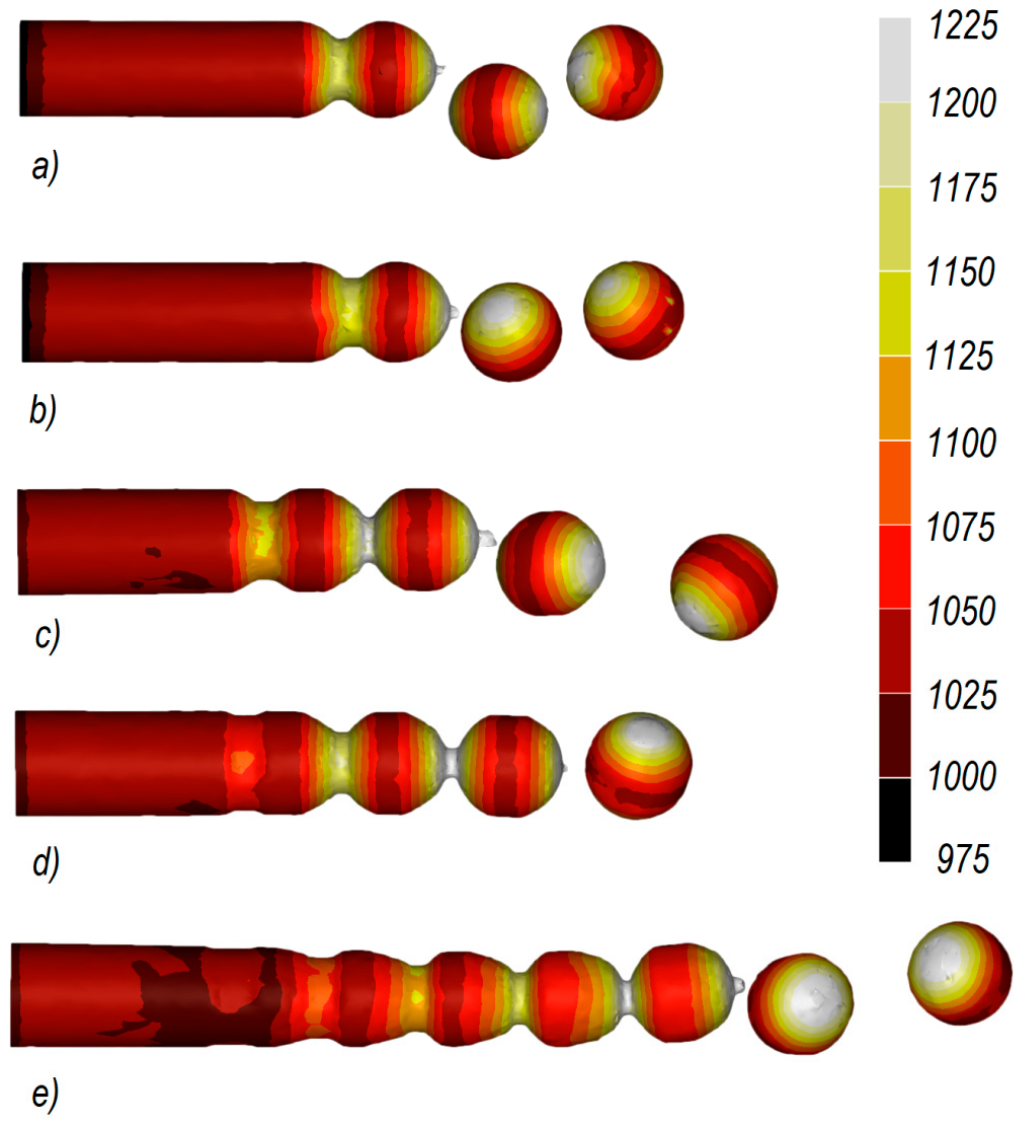
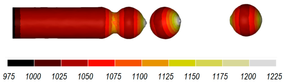
Figure 14 shows the distributions of temperature in balls rolled using flat discs. It can be observed that a significant temperature increase (up to 150 °C) occurs in the areas adjacent to the connectors joining the balls. This increase results from a conversion of frictional and plastic deformation work into heat. Due to the significant variations in temperature distribution, the balls should be left to cool down in open air after rolling to make their temperature uniform throughout their volume and to make it drop to the value recommended for hardening. It should be emphasized that a detailed comparative analysis of temperature fields was not the main objective of this study. In all analyzed rolling variants, the temperature of the balls after forming was higher than the temperature required for hardening C60 steel i.e., approximately 850 °C. Therefore, before hardening the balls should be held in air to equalize and reduce the temperature throughout their volume.

3.2. Ball Rolling Using Tapered Discs

One of the main problems in ball rolling with flat discs concerns the removal of scale that accumulates in the lower disc’s spiral impressions. This drawback can be eliminated by using discs whose spiral impressions are made tapered.
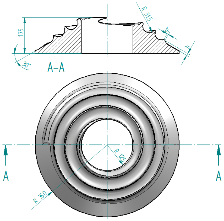
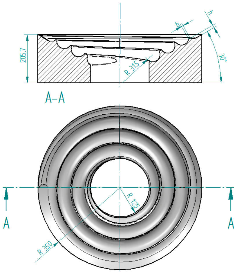
Figure 15 and Figure 16 show the tapered discs whose single spiral impressions are located along the taper generator inclined at an angle of 60° to the axis of rotation. These discs have the same outside diameter of 700 mm and a central hole with a diameter of 250 mm. They differ with respect to the design of their spiral working surface, which is located either on the outer surface of the taper (Figure 15) or on its inside (Figure 16).
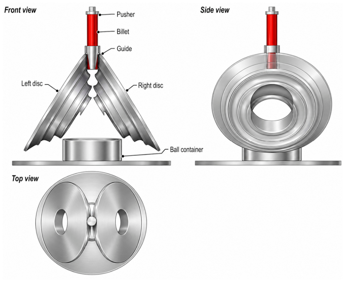
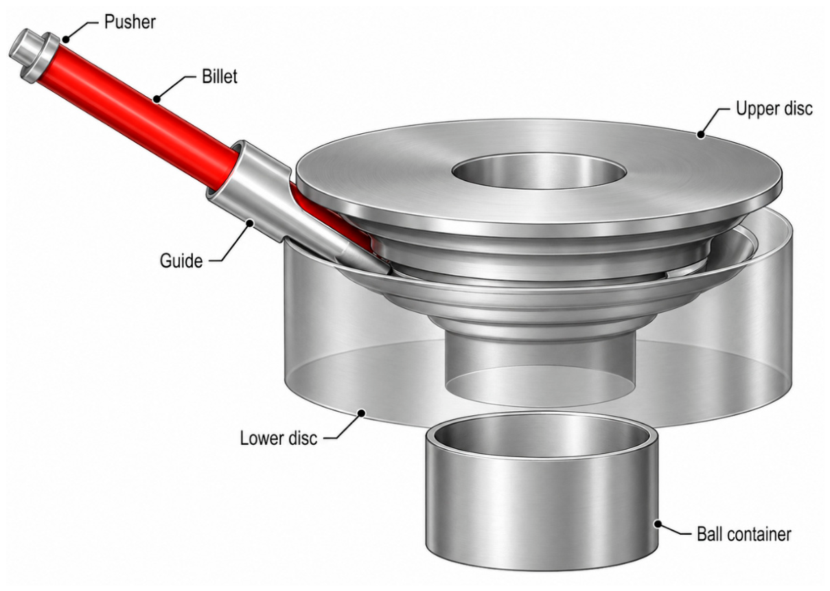
Ball rolling can be performed using two externally tapered discs that are arranged as shown in Figure 17. This case of ball rolling can only be performed using one billet that is fed vertically between the discs. The billet’s position is controlled by a tubular guide.
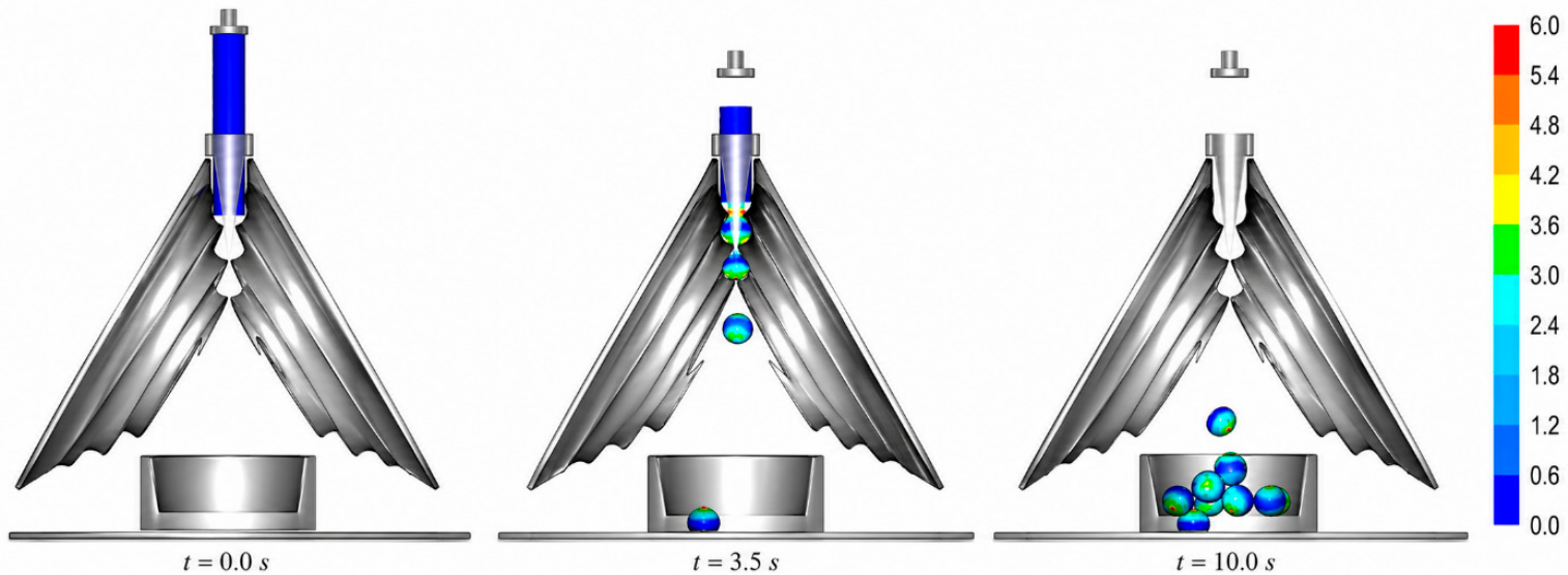
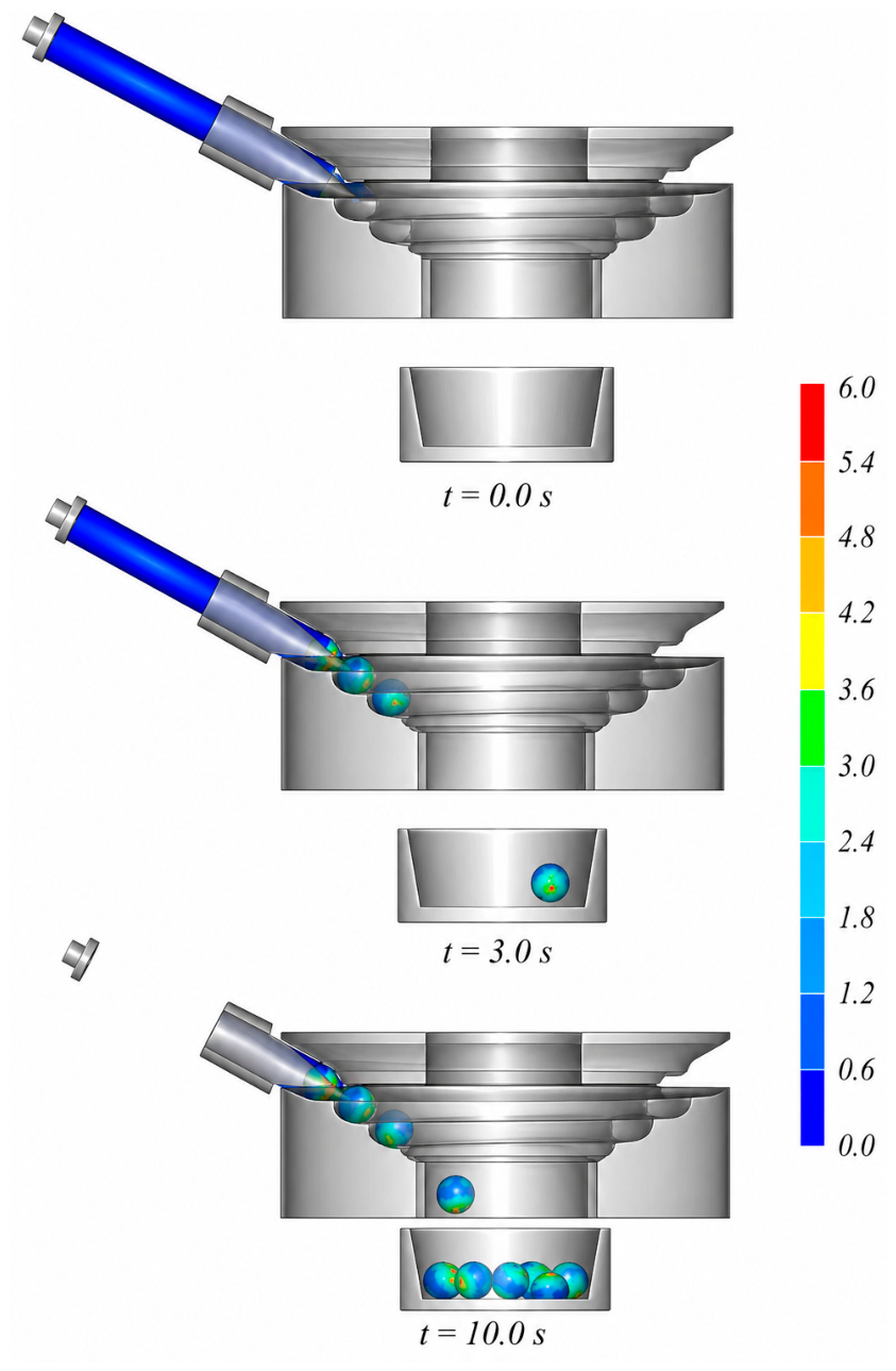
As the discs are rotated, their edges press into the workpiece, causing it to rotate and move downward toward the container (Figure 18). Once separated from the workpiece, a formed ball falls freely into the container. Scale is removed from the machine’s workspace in the same way. Balls formed by this process have the desired shape, and their temperature (Figure 19) allows for the necessary heat treatment to be performed.
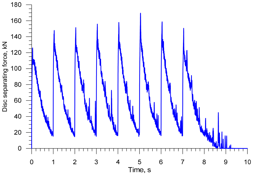
Figure 20 shows the distribution of the force acting on the discs during a rolling process conducted with two externally tapered discs. This force oscillates (with each revolution of the disc) between a minimum value of approximately 18 kN and a maximum value of 160 kN. The force curve is very similar to that obtained in the ball rolling process conducted with single-impression flat discs, using one billet.
The energy consumption of the ball rolling process conducted with two externally tapered discs can be calculated based on the torque distribution shown in Figure 21. The maximum torque determined for the steady-state phase of the rolling process (t = 3–6 s) is 13,151 Nm, while the mean torque is 4300.2 Nm. This means that the minimum drive power per disc is 82.6 kW and the energy required to produce a single ball is 54.0 kJ.
Due to the arrangement of two externally tapered discs, this ball rolling process can only be performed using one billet. This limitation does not apply when ball rolling is conducted using one externally tapered disc and one internally tapered disc, as shown schematically in Figure 22. In this case, the discs are mounted coaxially and rotate in opposite directions at the same speed. The cone generatrix is inclined at an angle of 60° to the axis of rotation, which corresponds to an angle of 30° relative to the plane perpendicular to this axis. Therefore, in the analyzed configuration, the billet is fed obliquely relative to the axis of the rotation of the discs, at an angle of 30°.
Figure 23 shows the ball rolling process conducted with externally and internally tapered discs, using one billet. The theoretical production capacity of this rolling process is 60 pieces per minute, which can easily be doubled by feeding in a second billet (symmetric to billet 1). The balls produced in this process have the correct shape, and their temperature distribution is typical of components produced by skew rolling processes (Figure 24).
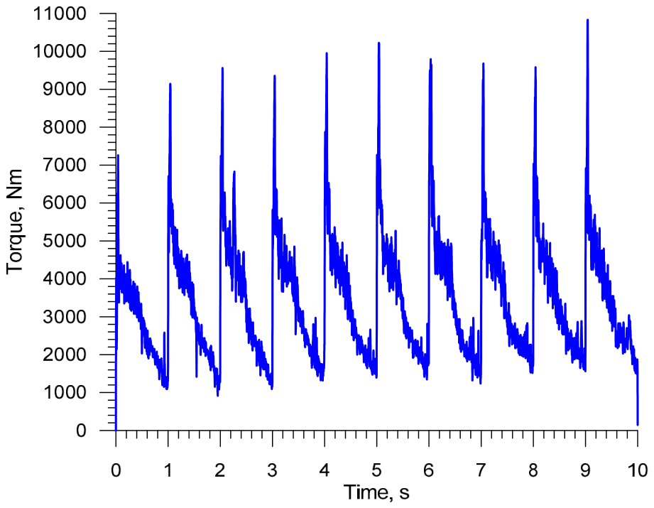
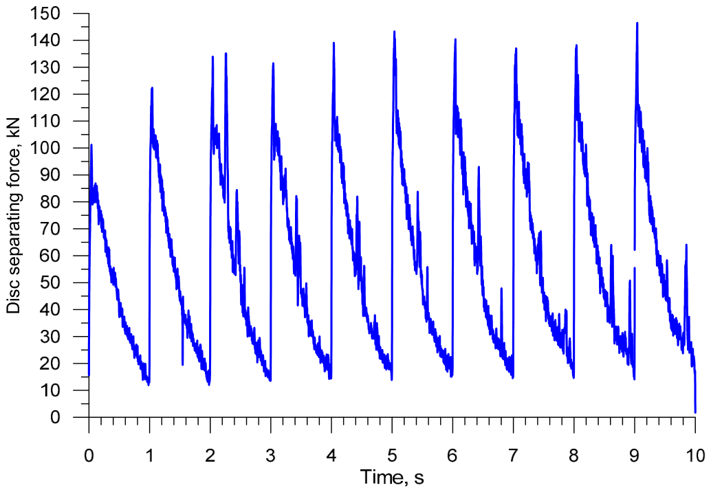
As for the force parameters, their distributions are almost identical to those observed during ball rolling with two externally tapered discs. For this case, the maximum force is 147 kN (Figure 25). In contrast, the mean torque (during the steady-state rolling phase at t = 3–7 s) is 3471.5 Nm, with the maximum torque being 10,836.4 Nm (Figure 26). The minimum drive power per disc determined based on the maximum torque is 68 kW. In turn, the energy required to form a single ball is 43.6 kJ, which is the lowest value among all analyzed cases of ball rolling with spiral discs. Although the geometry of tapered discs is more complex than that of flat discs, modern CNC machining technologies enable the precise manufacturing of such working surfaces. Therefore, the increased geometrical complexity of the proposed tools should not significantly limit their practical application.
The numerical simulations performed as part of this analysis are presented in the animations referenced in the Supplementary Materials section.

3.3. Discussion of the Results

The numerical analysis has demonstrated that ball rolling using spiral discs is a technologically feasible solution, with the produced balls having the correct shape and no internal defects, provided that suitable tool geometry is selected. The results have also confirmed that the effectiveness of the ball rolling process depends not only on the production capacity itself, but also on the relationship between ball quality and tool load.
Among the flat discs, single- and double-impression variants have proved to be the most advantageous. Compared to single-impression discs, double-impression ones allow for increased productivity while reducing specific energy consumption. At the same time, an increase in the number of billets leads to higher separating forces, torques, and power demand, indicating the need for a compromise between the increased efficiency of the ball rolling process and the requirements of the rolling mill design.
Different observations can be made about the use of triple-impression discs. Despite their very high theoretical production capacity, the use of these discs leads to the reduced geometric accuracy of formed balls and a significant increase in tool loads. This means that a further increase in the number of spiral impressions would not bring proportional technological benefits and might limit the practical application of this solution.
Compared to the flat discs, their tapered counterparts perform better. The main advantage of the tapered discs is that they reduce scale buildup in the workspace, which promotes higher process stability. Rolling with two externally tapered discs ensures the production of satisfactory quality balls at a forming energy of 54.0 kJ and a minimum drive power of 82.6 kW per disc. Even better results were obtained when ball rolling was conducted with one externally tapered disc and one internally tapered disc, where the forming energy per ball was 43.6 kJ and the minimum drive power was 68 kW. This renders it the most promising case of ball rolling among the analyzed configurations.
The temperature distributions also show local temperature variations after rolling, particularly in areas adjacent to the ball connectors. From a technical standpoint, this means that the balls must be left to cool down for a short time after rolling to allow the temperature to become uniform before further heat treatment.
It must be emphasized that the numerical results reported in this paper served as the basis for a comparative assessment of the analyzed cases of ball rolling. In future research, these results should be verified experimentally, particularly for the ball rolling process conducted with one externally tapered disc and one internally tapered disc owing to its greatest application potential.

4. Conclusions

The numerical results confirm that 63 mm diameter balls can be rolled using spiral discs, provided that an appropriate tool geometry is selected.
Among the tested flat discs, single- and double-impression variants are the most effective, ensuring the required quality of the balls and high efficiency of the rolling process at the same time.
Although double-impression discs are more effective than single-impression ones in terms of energy consumption, an increase in the number of billets leads to higher torques and higher drive power demand.
Despite their high efficiency, the use of triple-impression discs results in the reduced accuracy of produced balls and considerably higher tool loads; therefore, their use in the production of grinding media should be limited.
The use of tapered discs reduces the scale buildup which occurs in rolling conducted with flat discs.
The system comprising one externally tapered disc and one internally tapered disc is the most effective solution; it is characterized by the lowest energy consumption and power demand among all the investigated solutions.

Supplementary Materials

The following supporting information can be downloaded at: https://www.mdpi.com/article/10.3390/met16060593/s1, Video S1: balls0.avi; Video S2: balls1.avi; Video S3: balls2.avi; Video S4: balls3.avi.

Funding

This research received no external funding.

Data Availability Statement

The raw data supporting the conclusions of this article will be made available by the authors on request.

Acknowledgments

In preparing this manuscript/study, the author used ChatGPT 5.3 to improve the clarity of the figures, particularly the models illustrating new methods of ball rolling. The author has checked and edited the results and takes full responsibility for the content of this publication.

Conflicts of Interest

The author declares no conflicts of interest.

References

  1. Wang, Q.; Wang, Q.; Xu, J. Study on the method for groove design in the helical rolling of steel balls. J. Mater. Process. Technol. 1995, 55, 340–344. [Google Scholar] [CrossRef]
  2. Yang, S.C.; Chen, C.K. The surface geometry of rollers with skew rolling of steel balls. Proc. Inst. Mech. Eng. Part C 2001, 215, 523–532. [Google Scholar] [CrossRef]
  3. Peretyat’ko, V.N.; Klimov, A.S.; Filippova, M.V. Roller grooving in ball-rolling mills. Part 1. Steel Transl. 2013, 43, 168–170. [Google Scholar] [CrossRef]
  4. Rubtsov, V.Y.; Shevchenko, O.I. Development of new roll pass designs for ball-rolling rolls with continuously variable parameters. IOP Conf. Ser. Mater. Sci. Eng. 2020, 966, 012070. [Google Scholar] [CrossRef]
  5. Shi, X.; Wang, B.; Li, Z. Optimization of pass parameters on two-grooves skew rolling for Al ball. Key Eng. Mater. 2010, 419–420, 313–316. [Google Scholar] [CrossRef]
  6. Tomczak, J.; Pater, Z.; Bulzak, T. Designing of screw impressions in the helical rolling of balls. Arch. Civ. Mech. Eng. 2014, 14, 104–113. [Google Scholar] [CrossRef]
  7. Pater, Z.; Tomczak, J.; Bartnicki, J.; Bulzak, T. Thermomechanical analysis of a helical-wedge rolling process for producing balls. Metals 2018, 8, 862. [Google Scholar] [CrossRef]
  8. Pater, Z. Numerical analysis of helical rolling process for producing steel balls. Int. J. Mater. Prod. Technol. 2016, 55, 137–153. [Google Scholar] [CrossRef]
  9. Wójcik, Ł.; Pater, Z.; Bulzak, T.; Tomczak, J.; Lis, K. A comparative analysis of the physical modeling of two methods of balls separation. Materials 2021, 14, 7126. [Google Scholar] [CrossRef] [PubMed]
  10. Galimyanov, I. Analysis of single- and double-threaded rolling for production of grinding balls of alloy steel grades. IOP Conf. Ser. Mater. Sci. Eng. 2020, 966, 012009. [Google Scholar] [CrossRef]
  11. Shvarts, D.L.; Galimyanov, L.K. Improvement of double-helical roll pass design for rolling 100-mm grinding balls. Metalurgist 2022, 66, 422–432. [Google Scholar] [CrossRef]
  12. Tomczak, J.; Pater, Z.; Bartnicki, J. Screw rolling of balls in multiple helical impressions. Arch. Metall. Mater. 2013, 58, 1071–1076. [Google Scholar] [CrossRef]
  13. Bulzak, T.; Majerski, K.; Tomczak, J.; Pater, Z.; Wójcik, Ł. Warm skew rolling of bearing steel balls using multiple impression tools. CIRP J. Manuf. Sci. Technol. 2022, 38, 288–298. [Google Scholar] [CrossRef]
  14. Pater, Z. A thermomechanical analysis of the multi-wedge helical rolling (MWHR) process for producing balls. Metalurgija 2016, 55, 233–236. [Google Scholar]
  15. Kotennok, V.I.; Podobedov, S.I. Energy-efficient design of rolls for ball-rolling mills. Metalurgist 2001, 45, 363–367. [Google Scholar] [CrossRef]
  16. Shi, X.; Wang, B. Numerical simulation of Al ball forming process in skew rolling. Mater. Sci. Forum 2012, 704–705, 151–154. [Google Scholar] [CrossRef]
  17. Ren, X.; Liu, Y. Study on the influence of determining velocity on steel ball quality based on DEFORM. Appl. Mech. Mater. 2012, 117–119, 1806–1809. [Google Scholar] [CrossRef]
  18. Pater, Z.; Tomczak, J.; Bartnicki, J.; Lovell, M.; Menezes, P. Experimental and numerical analysis of helical-wedge rolling process for producing steel balls. Int. J. Mach. Tools Manuf. 2013, 67, 1–7. [Google Scholar] [CrossRef]
  19. Gontarz, A.; Tomczak, J.; Pater, Z.; Bulzak, T. Effect of the forming zone length on helical rolling processes for manufacturing steel balls. Materials 2019, 12, 2917. [Google Scholar] [CrossRef]
  20. Cao, Q.; Hua, L.; Qian, D. Finite element analysis of deformation characteristics in cold helical rolling of bearing steel balls. J. Cent. S. Univ. 2015, 22, 1175–1183. [Google Scholar] [CrossRef]
  21. Zhou, J.; Liu, S.; Wang, B.; Xu, H. Numerical prediction of microstructure evolution of small-diameter stainless steel balls during cold skew rolling. Materials 2023, 16, 3246. [Google Scholar] [CrossRef] [PubMed]
  22. Gao, X.S.; Shu, X.D.; Chen, X.; Ding, L.; Sun, B.S. Effect of process parameters on microstructure of 42CrMo steel ball hot skew rolling. Metalurgija 2022, 61, 693–696. [Google Scholar]
  23. Huo, Y.; He, T.; Wang, B.; Zheng, Z.; Xue, Y. Numerical prediction and experimental validation of the microstructure of bearing steel ball formation in warm skew rolling. Metall. Mater. Trans. A 2020, 51, 1254–1263. [Google Scholar] [CrossRef]
  24. Huo, Y.; He, T.; Wang, B.; Zheng, Z.; Yang, W.; Hu, Y.; Shen, M. Forming analysis of steel ball bearings made with warm skew rolling. Mater. Tehnol. 2020, 54, 417–422. [Google Scholar] [CrossRef]
  25. Shu, C.; Wang, J.; Shu, X.; Tian, D. Influencing factors of void closure in skew-rolled steel balls based on the floating-pressure method. Materials 2019, 12, 1391. [Google Scholar] [CrossRef]
  26. Beygelzimer, Y.; Beygelzimer, E.; Hajduk, D. Engineering estimates of strain and strain rate in helical rolling of balls. Int. J. Mater. Form. 2024, 17, 32. [Google Scholar] [CrossRef]
  27. Du, S.; Ren, X.; Liu, Y. Analysis of factors influencing the skew rolling ball quality. Mach. Des. Manuf. 2013, 2, 248–250. [Google Scholar]
  28. Stalinskii, D.V.; Rudyuk, A.S.; Solenyi, V.K.; Yudin, A.V. Improving the quality of steel grinding balls. Steel Transl. 2017, 47, 130–136. [Google Scholar] [CrossRef]
  29. Zurandzhy, V.I.; Efremenko, V.G.; Wu, K.M.; Lekatou, A.G.; Shimizu, K.; Chabak, Y.G.; Zotov, D.S.; Dunayev, E.V. Quenching and partitioning-based heat treatment for rolled grinding steel balls. Metall. Mater. Trans. A 2020, 51, 3042–3053. [Google Scholar] [CrossRef]
  30. Shevchenko, O.I.; Trekin, G.I.; Rubtsov, V.Y.; Kurochkin, V.V. Thermal treatment of grinding balls in a new ball-rolling shop. Bull. PNRPU Mech. Eng. Mater. Sci. 2019, 21, 110–117. [Google Scholar] [CrossRef]
  31. Lam, M.M.; Serov, A.I.; Ternavskiy, A.A.; Bazarova, G.S.; Smyrnov, Y.N. Heat treatment of rollers in the ShPS 30–80 ball-rolling mill at JSC DMPZ. Steel Transl. 2015, 45, 784–788. [Google Scholar] [CrossRef]
  32. Umanskii, A.A.; Simachev, A.S.; Dumova, L.V. Analysis of special features of microstructure of grinding balls produced from rejected continuously cast rail steel billets of different chemical compositions. Mater. Sci. Heat Treat. 2023, 64, 672–678. [Google Scholar] [CrossRef]
  33. Rubtsov, V.Y.; Shevchenko, O.I.; Spirina, A.S.; Pankova, N.A. Research into in-service deterioration of ball-rolling rolls. IOP Conf. Ser. Mater. Sci. Eng. 2020, 966, 012069. [Google Scholar] [CrossRef]
  34. Shvarts, D.L.; Galim’yanov, I.K.; Rubtsov, V.Y. Tuning parameters of a ball-rolling mill for rolling of grinding balls. Russ. Metall. 2023, 13, 2230–2236. [Google Scholar] [CrossRef]
  35. Kruse, J.; Jagodzinski, A.; Langner, J.; Stonis, M.; Behrens, B.A. Investigation of the joining zone displacement of cross-wedge rolled serially arranged hybrid parts. Int. J. Mater. Form. 2020, 13, 577–589. [Google Scholar] [CrossRef]
  36. Murillo-Marrodán, A.; Bulzak, T.; García, E.; Aghajani Derazkola, H.; Majerski, K.; Tomczak, J.; Pater, Z. Effect of warm forming process parameters on 42CrMo4 skew rolled bar mechanical properties and microstructure. Arch. Civ. Mech. Eng. 2024, 24, 90. [Google Scholar] [CrossRef]
  37. Singh, G.; Singh, P.K. Process variable optimization for hot-profiled rolling of SAE 52100 steel. Int. J. Precis. Eng. Manuf. 2023, 24, 1425–1433. [Google Scholar] [CrossRef]
  38. Surdacki, P.; Gontarz, A.; Winiarski, G.; Wójcik, Ł.; Wiewiórowska, S. Research of speed parameters of the ring rolling process. Adv. Sci. Technol. Res. J. 2022, 16, 251–257. [Google Scholar] [CrossRef]
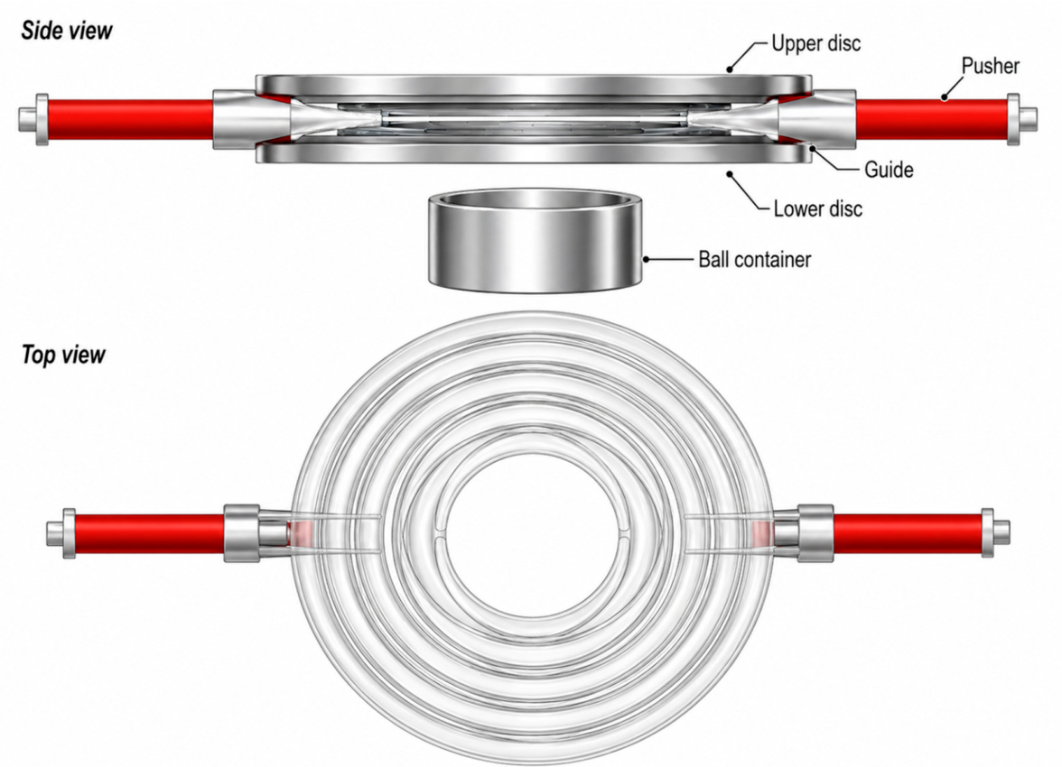
Figure 1. Geometric model of ball rolling with double-impression flat discs, designed in Forge®.
Metals 16 00593 g001
Figure 2. Flat disc with a single spiral impression, used for rolling 63 mm diameter balls.
Metals 16 00593 g002
Figure 3. Flat disc with a double spiral impression, used for rolling 63 mm diameter balls.
Metals 16 00593 g003
Figure 4. Flat disc with a triple spiral impression, used for rolling 63 mm diameter balls.
Metals 16 00593 g004
Figure 5. Stages of a ball rolling process conducted with single-impression flat discs, using one billet (a) and two billets (b), along with the distribution of effective strains.
Metals 16 00593 g005
Figure 6. Disc separating force in a ball rolling process conducted with single-impression flat discs.
Metals 16 00593 g006
Figure 7. Torque in a ball rolling process conducted with single-impression flat discs.
Metals 16 00593 g007
Figure 8. Stages of a ball rolling process conducted with double-impression flat discs, using two billets (a) and four billets (b), along with the distribution of effective strains.
Metals 16 00593 g008
Figure 9. Disc separating force in a ball rolling process conducted with double-impression flat discs.
Metals 16 00593 g009
Figure 10. Torque in a ball rolling process conducted with double-impression flat discs.
Metals 16 00593 g010
Figure 11. Stages of a ball rolling process conducted with triple-impression flat discs, using three billets, and the distribution of effective strains.
Metals 16 00593 g011
Figure 12. Disc separating force in a ball rolling process conducted with triple-impression flat discs, using three billets.
Metals 16 00593 g012
Figure 13. Torque in a ball rolling process conducted with triple-impression flat discs, using three billets.
Metals 16 00593 g013
Figure 14. Balls (and their distribution of temperature in °C) rolled with flat discs: (a) single-impression, using one billet, (b) single-impression, using two billets, (c) double-impression, using two billets, (d) double-impression, using four billets, (e) triple-impression, using three billets.
Metals 16 00593 g014
Figure 15. Single-impression disc with its working surface shaped as an external taper, used for rolling balls with a diameter of 63 mm.
Metals 16 00593 g015
Figure 16. Single-impression disc with its working surface shaped as an internal taper, used for rolling balls with a diameter of 63 mm.
Metals 16 00593 g016
Figure 17. Geometric model of a ball rolling process conducted with externally tapered discs, designed in Forge®.
Metals 16 00593 g017
Figure 18. Stages of a ball rolling process conducted with externally tapered discs, and the distribution of effective strains.
Metals 16 00593 g018
Figure 19. Balls produced by rolling with externally tapered discs, and the distribution of temperature in °C.
Metals 16 00593 g019
Figure 20. Disc separating force in a ball rolling process conducted with externally tapered discs, using one billet.
Metals 16 00593 g020
Figure 21. Torque in a ball rolling process conducted with externally tapered discs, using one billet.
Metals 16 00593 g021
Figure 22. Geometric model of a ball rolling process conducted with externally and internally tapered discs, designed in Forge®.
Metals 16 00593 g022
Figure 23. Stages of a ball rolling process conducted with externally and internally tapered discs, and the distribution of effective strains.
Metals 16 00593 g023
Figure 24. Balls produced by rolling with externally and internally tapered discs, and the distribution of temperature in °C.
Metals 16 00593 g024
Figure 25. Disc separating force in a ball rolling process conducted with externally and internally tapered discs using one billet.
Metals 16 00593 g025
Figure 26. Torque in a ball rolling process conducted with externally and internally tapered discs using one billet.
Metals 16 00593 g026
Disclaimer/Publisher’s Note: The statements, opinions and data contained in all publications are solely those of the individual author(s) and contributor(s) and not of MDPI and/or the editor(s). MDPI and/or the editor(s) disclaim responsibility for any injury to people or property resulting from any ideas, methods, instructions or products referred to in the content.