


Abstract
Despite their potential to improve properties such as the high-temperature strength required for jet engine blades, low-Al TiAl alloys have largely been overlooked. The most significant challenge is ensuring impact resistance, which is crucial for jet engine blade applications. First, this study evaluated the impact resistance of fully lamellar Ti-38.75–50.25 Al binary alloys in relation to the effects of α2 phase ratio and spacing using a Charpy impact test. Subsequently, the impact of reducing Al content in Cr-added forged alloys and cast TiAl4822 was investigated. The results revealed that α2 phase spacing had the most significant impact on impact resistance at 800 °C. Coarse α2 phase spacing of approximately 6 μm, created in the high-Al material, provided the highest impact resistance. In contrast, the impact resistance of the low-Al material was low due to its extremely narrow α2 phase spacing. In forged alloys, reducing both Al content and β-stabilizing elements enabled the removal of the deleterious β phase through heat treatment, while maintaining good forgeability, thereby improving impact resistance and creep strength. In low-Al TiAl4822, the expected improvement in creep strength could not be achieved because the low-strength γ phase located at lamellar colony boundaries underwent preferential deformation.
1. Introduction
In recent years, lightweight TiAl alloys with excellent heat resistance have garnered significant attention as promising materials for enhancing engine performance. Both cast and forged TiAl alloys have been put into practical use in jet engines. Cast TiAl4822 [1] (Ti-48Al-2Nb-2Cr at% (at% notation is omitted hereinafter) is the representative alloy, which is widely used in the last-stage turbine blades of turbofan engines such as the GEnx and Leap [2,3], contributing significantly to improved engine efficiency.
The main challenge of using TiAl alloys for jet engine blades is that they are significantly more brittle and less reliable than Ni-based superalloys, which are conventionally used for the same components. Reduced impact resistance is the most critical consideration associated with this brittleness. For example, the TNM alloy [4] (Ti-43.5Al-4Nb-1Mo-0.1B), which is a forged TiAl alloy that was commercialized following TiAl4822 and adopted for the last-stage turbine blades of the PW1100G geared turbofan engine, experienced frequent impact-related failures during service as a result of collisions with debris. Consequently, its installation was discontinued, and it was replaced with conventional Ni-based superalloy blades in all engines [5]. The stark result demonstrates the inherent brittleness of TiAl alloys and underscores impact resistance as the most critical property for their application in jet engine blades. Furthermore, TiAl4822 has been considered to transform into a ductile material similar to conventional metals at high temperatures, as tensile tests or creep tests (static stress loading) conducted above 900 °C yield elongation of over several tens of percent. However, the results from Charpy impact tests (dynamic stress loading) performed at 1000 °C [6] showed fractures with very low absorbed energy and exhibited a brittle fracture surface. This indicates that TiAl alloys exhibit significantly inferior dynamic fracture behavior compared to conventional metallic materials. Consequently, impact resistance evaluation is particularly critical, especially for jet engine blades.
TiAl alloys are also known as “gamma alloys.” As their name suggests, these alloys primarily consist of the γ phase. Furthermore, the Al content of TiAl alloys developed to date has largely been confined to the range of 45–48%, particularly in cast alloys, making them γ-phase-dominant alloys. Conversely, research on α2-phase-dominated low-Al TiAl alloys with an Al content of 43% or less [7,8,9] remains comparatively limited. However, the combination of γ and α2 phases in a lamellar structure demonstrates improved properties, including enhanced creep strength [7,10,11] and fracture toughness [12,13]. Thus, if the improved properties of lamellar structures originate from the formation of a layered composite of the γ and α2 phases—specifically through refinement (thinning) of each phase and interfacial effects—similar effects can potentially occur in α2-dominant lamellar structures. Furthermore, since the α2 phase exhibits greater hardness than the γ phase [13], it has the potential to provide the superior high-temperature strength required for TiAl alloys used in blades for next-generation jet engines. Therefore, confirming the practical value as jet engine blade material of low-Al TiAl alloys dominated by the α2 phase, which has received insignificant attention to date, is considered to be of certain significance. However, the primary concern with low-Al TiAl alloys is that they may be even more brittle than conventional TiAl alloys, with the aforementioned reduction in impact resistance representing the most significant challenge.
Regarding forged TiAl alloys used in jet engine blades (such as the TNM alloy), stabilization of the β phase is required through the addition of substantial amounts of β-stabilizing elements, such as Cr, Mn, Mo, and W. This β phase becomes disordered at high temperatures, transforming into a metallic phase followed by softening. Consequently, it enables plastic deformation at high temperatures. However, the β phase exhibits the drawback of converting to an intermetallic B2 phase at low temperatures, causing hardening and embrittlement [14] and reducing overall ductility [15]. Moreover, numerous studies have demonstrated the detrimental effects of the β phase. These effects include reduced fatigue strength owing to preferential oxidation of the β phase [16,17] and decreased creep strength [18,19]. Therefore, in forged TiAl alloys for jet engine blades, removal of the β phase is required through post-forging heat treatment. However, this has not yet been achieved. Furthermore, recent reports have demonstrated superior material properties by achieving a fully lamellar structure through hot working or heat treatment in the α single-phase region [20,21]. However, these methods require specialized processes, such as hot working with the sample enclosed in a metal sheath, making their application to jet engine blades—the focus of this study—still challenging due to cost and shape constraints.
On the other hand, the phase diagram of Ti-43Al-Cr reported by Shaaban et al. [22] reveals that when the Cr content is maintained below approximately 1.7%, the β phase exists in the high-temperature region but disappears at low temperatures. This suggests that the alloy is forgeable and the β phase can be eliminated through subsequent heat treatment. Nevertheless, the temperature range over which the β phase exists in this phase diagram is extremely high (approximately 1400 °C and above), making forging with general-purpose industrial equipment challenging. Therefore, to realize the behavior indicated by this phase diagram, namely, enabling forging while subsequently removing the β phase through heat treatment, the β phase stability range must be shifted to lower temperatures.
Furthermore, as mentioned above, cast TiAl4822 is currently used extensively in jet engine blades. However, future engines are expected to operate at higher temperatures, which necessitates improved creep strength. To this end, reducing the Al content may contribute by increasing the proportion of the harder α2 phase.
In view of the above considerations, the following three investigations were conducted in this study. At first, (i) using samples of binary TiAl alloys with fully lamellar structures, the effects of the α2 phase ratio and spacing on impact resistance at 25 and 800 °C (the expected maximum temperature in next-generation engines) were assessed, while also confirming the impact resistance levels of low-Al TiAl alloys. Next, (ii) the property changes associated with reducing the Al and Cr contents in Cr-containing forged alloys were investigated. A decrease in Al concentration is expected to lower the temperature range in which the β phase exists, thereby enabling forging on general-purpose equipment. A reduction in Cr content is expected to eliminate the harmful β phase through heat treatment. Finally, (iii) the impact resistance and creep strength of cast TiAl4822 with reduced Al content were investigated.
The objective of this study, conducted through the three investigations described above, is to clarify whether low-Al TiAl alloys with α2 phase-dominant fully lamellar structures—which have received insignificant attention to date—possess practical feasibility as materials for jet engine blades.
2. Materials and Methods
2.1. Materials
The alloy compositions used in examinations (i)–(iii) are as follows: (i) To analyze the influences of the α2 phase ratio and spacing on impact resistance, binary TiAl alloys with Al contents ranging from 38.75 to 50.25% (in 0.75% increments) were used. (ii) To investigate the effects of variations in the Al- and β-stabilizing element contents in forged alloys, the initial composition was set to 43.5 Al (corresponding to the Al content of the TNM alloy)-1.5 Cr-0.2 B. Two compositional series were then examined: one with increasing Cr contents (2.0, 2.5, 3.0, and 3.5 Cr) and another with decreasing Al contents (43.0, 42.5, 42.0, 41.5, and 41.0 Al). B was added to suppress extreme grain coarsening. (iii) To analyze the influences of decreasing Al content of cast TiAl4822, Ti-42.0Al-2.0Nb-1.0Cr and Ti-47.0Al-2.0Nb-2.0Cr were employed. For the former low-Al alloy, the Cr content was reduced to 1% to prevent the formation of the β phase. The latter high-Al alloy is a reference material. As TiAl4822 with slightly reduced Al content is currently widely used [23], the Al content was set at 47.0%.
Sponge Ti, Al pellets, Nb flakes, Cr granules, and TiB2 powder were utilized as raw materials. Weight per charge was approximately 500 g for evaluating cast materials and 850 g for forging ingots. After evacuation of the chamber followed by Ar purging, the raw materials were melted in a CaO crucible using an induction melting furnace. During this process, 0.2 wt% Ca was added in the form of an Al-10 wt% Ca alloy for deoxidation. This addition has been shown to reduce the O concentration in the cast material to 0.1 wt% or less [14]. After complete melting of the raw materials, the molten metal was held under a constant power load for 4 min before being poured into a cast iron mold. The resulting material evaluated as a cast material consisted of a flat plate containing test-specimen sampling parts measuring 60 × 90 × 16 mm3, with a riser section positioned above it. This cast material was subjected to hot isostatic pressing (HIP) at 1200 °C for 4 h under 186 MPa to eliminate internal casting defects. The ingot used for forging measured approximately 55 mm in diameter and 90 mm in height. After being heated at 1330 °C for 1 h, the ingot was removed from the furnace and formed into a 16 mm-thick pancake by single upset forging in the height direction using a 300-ton hydraulic press. The forgeabilities of all alloys were compared based on the occurrence of surface cracks.
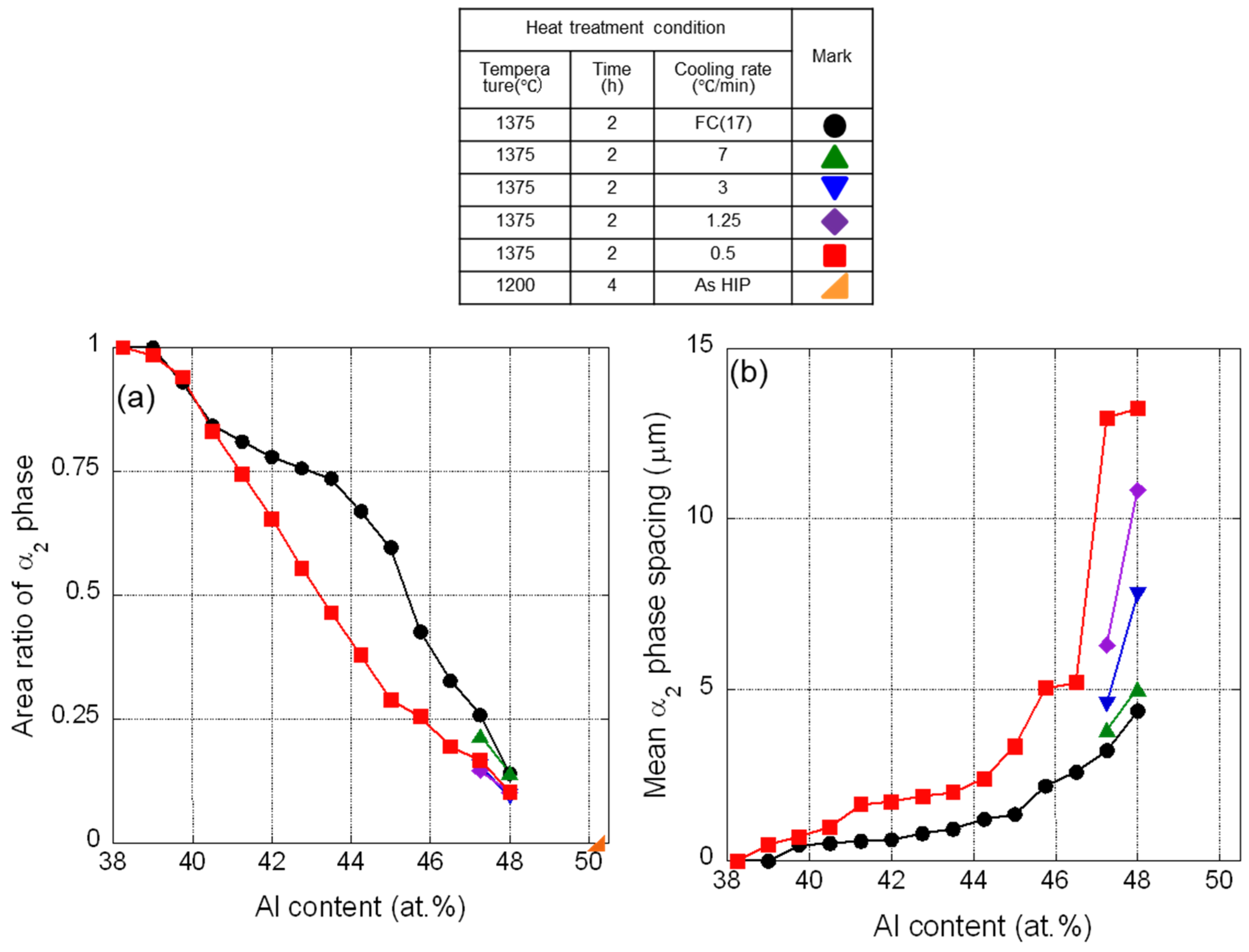
Regarding heat treatment, for (i), the specimens were maintained at 1375 °C for 2 h after HIP, followed by cooling under five conditions: furnace cooling (FC) (at approximately 17 °C/min) and cooling at 7, 3, 1.25, and 0.5 °C/min (divided at approximately 2.5-fold intervals) to approximately 1200 °C. The cooling rate was varied to change the α2 phase spacing. FC and cooling at a rate of 0.5 °C/min were applied to all samples, whereas the intermediate cooling rates were applied only to high-Al alloys (47.25 and 48.0 Al). The reason is that the α2 phase spacing is expected to be inherently narrow in low-Al alloys, leading to the assumption that the effect of the cooling rate would be minimal. The average lamellar colony size was 500 μm or larger in all cases. Chan and Kim [24] reported no significant difference in fracture toughness values for colony sizes of 500 μm or larger in TiAl alloys with fully lamellar structures. Therefore, the influence of lamellar colony size is considered to be minimal, even in the evaluation of impact resistance. Furthermore, for the composition targeting the γ single phase (50.25 Al), 1375 °C lies within the γ + α2 phase region [25]; therefore, the abovementioned heat treatment was not employed. Instead, the material in the as-HIPed condition at 1200 °C was used. Regarding (ii), a heat treatment was first conducted at 1330 °C for 1 h—the same condition used for forging—followed by water quenching to estimate the β phase ratio during forging. Furthermore, heat treatment tests were performed on small pieces cut from the forged material. These tests involved holding at 1200, 1240, and 1280 °C for 5 h, followed by cooling at 5 °C/min. Optimal conditions were chosen according to microstructural observations. For (iii), evaluation was conducted on the material in the as-HIPed condition at 1200 °C.
2.2. Evaluation Methods
After polishing the region corresponding to approximately the center of the plate thickness in the cast and forged materials, their microstructures were analyzed using a JEOL JSM-6060 scanning electron microscope (JEOL Ltd., Akishima, Japan) operated in backscattered electron imaging at 20 kV. The area fractions of the α2 and β phases, as well as the α2 phase spacing, were determined from five backscattered electron images per sample, utilizing image processing techniques and direct measurement.
Impact resistance assessment was performed via the Charpy impact test at temperatures ranging from 25 to 900 °C, which is the simplest and most industrially practical method for evaluating impact resistance of industrial material. It has been confirmed that the results obtained from the Charpy impact test are comparable to those obtained from tests involving the collision of a small iron ball propelled by gas pressure with a specimen [26], which are commonly employed as foreign-object-damage simulations for jet engine blade impacts. Details of the Charpy impact test are provided in a separate study [14]. Front and back surfaces and sides of the flat cast and forged materials after HIP or heat treatment were cut and machined to produce flat test specimens approximately 55 mm in width and 10 mm in thickness. Then, these specimens were cut using a diamond grinding wheel under low load to create a cutting surface close to the polished surface, generating rectangular prism test specimens measuring approximately 10 × 10 × 55 mm3. Due to the extremely low impact resistance of TiAl alloys, no notches were introduced into the test specimens, and a small hammer with a capacity of 50 J was used to clearly differentiate the alloys. Charpy impact tests were conducted using the cut surfaces as the front and rear faces of the impact surface. For the high-temperature tests, the test specimens were heated for approximately 1 h in an electric furnace installed adjacent to the testing machine. Subsequently, the heated specimens were rapidly set in the testing machine for testing. Testing was completed within 5–10 s of removal from the furnace. Approximately 10 tests were performed under each condition, and impact resistances of all alloys were compared based on the average absorbed energy.
To assess the high-temperature strength properties, tensile creep tests were conducted on round-bar specimens with gauge diameters of 4 mm at 775 °C under 200 MPa, using Ultra-High Temperature Creep Rupture Testing Equipment (Toshin Kogyo Ltd., Tokyo, Japan).
3. Results and Discussion
3.1. Effects of α2 Phase Ratio and Spacing on the Impact Resistances of TiAl Alloys with Fully Lamellar Structures
3.1.1. Microstructure
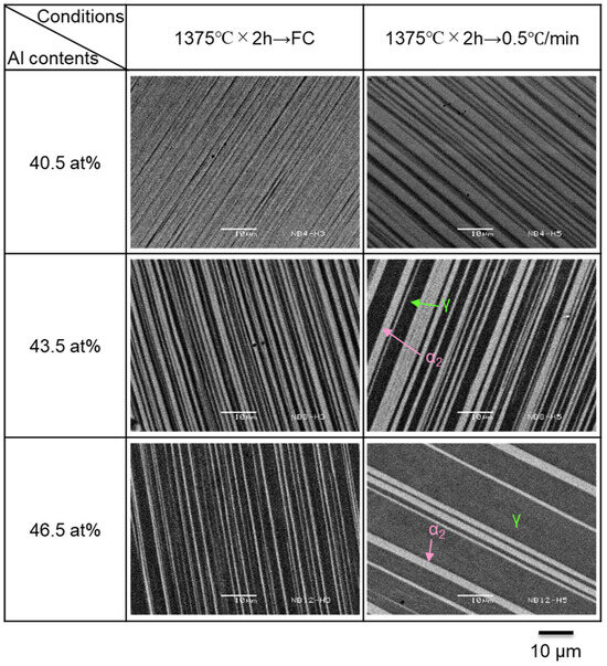
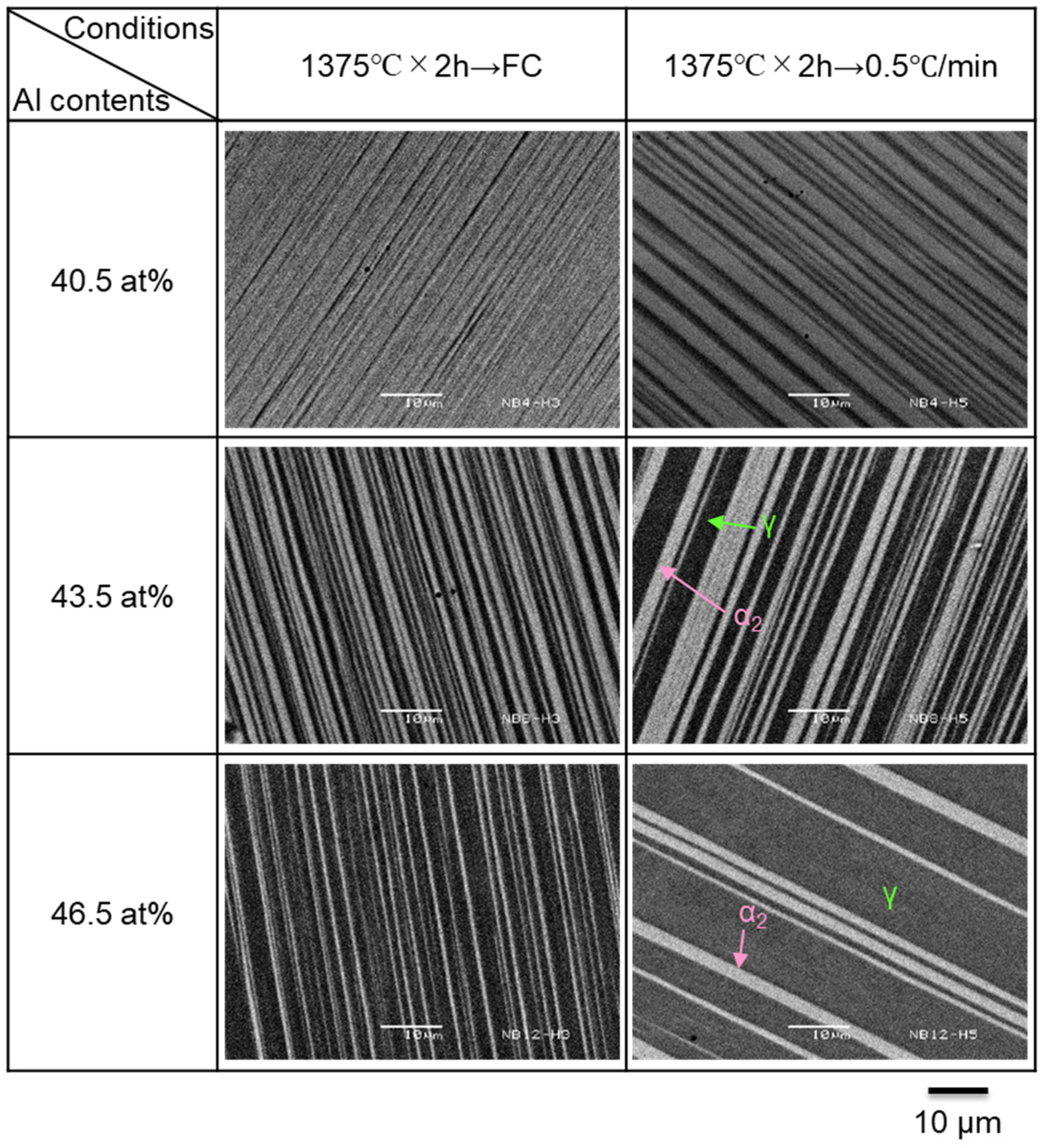
Figure 1 shows representative microstructures of TiAl alloys held at 1375 °C for 2 h, followed by FC and cooling at 0.5 °C/min. For 40.5 Al, FC conditions lead to very high α2 phase ratio and extremely narrow α2 phase spacing. At a cooling rate of 0.5 °C/min, a slight decrease in the α2 phase ratio and slight increase in α2 phase spacing are noticed. In contrast, for 43.5 Al, the α2 phase ratio decreases under both cooling conditions, while the α2 phase spacing increases relative to that observed in 40.5 Al. Moreover, for 46.5 Al, this trend is even more significant; at a cooling rate of 0.5 °C/min, a fully lamellar structure with wide α2 phase spacing is observed.
Figure 1.
Backscattered electron images showing the microstructures of representative Ti-xAl alloys with different Al contents heat-treated under different conditions.
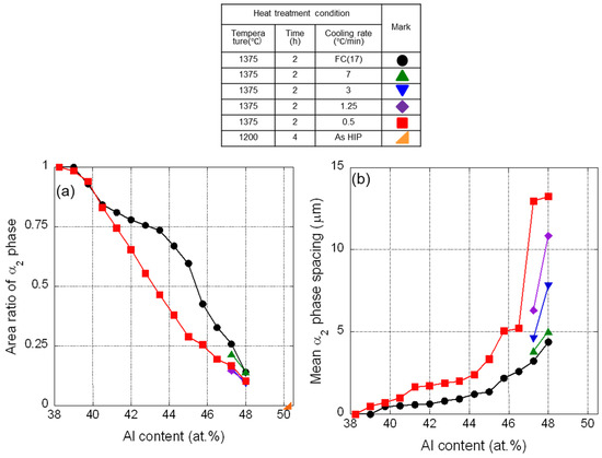
Figure 2 depicts the relationships of Al content with α2 phase ratio and spacing for each heat treatment condition. Note that 48.75 and 49.5 Al are not shown because 1375 °C lies outside the α single-phase region [25] for these compositions, and a fully lamellar structure did not form. As mentioned earlier, 50.25 Al is a material as-HIPed at 1200 °C. The α2 phase ratio is unity (corresponding to the α single-phase region) at 38.25 Al. With increasing Al content, this ratio decreases progressively, reaching zero (corresponding to the γ single-phase region) at 50.25 Al. Additionally, the α2 phase ratio decreases with a decrease in the cooling rate, even at the same Al concentration, particularly in the intermediate Al concentration range. Contrarily, the α2 phase spacing is zero at 38.25 Al and increases with increasing Al concentration. Furthermore, an increase in α2 phase spacing with a decrease in the cooling rate is specifically evident at Al concentrations of 46% and above. These results imply that in the fully lamellar structure, the α2 phase ratio and spacing are interdependent and cannot be independently controlled. Therefore, low-Al TiAl alloys can only produce fully lamellar structures characterized by very high α2 phase ratios and correspondingly narrow α2 phase spacings.
Figure 2.
Relationship between Al content and the (a) α2 phase ratio and (b) α2 phase spacing for Ti-xAl alloys heat-treated under different conditions.
3.1.2. Impact Resistance
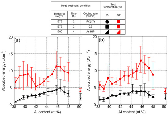
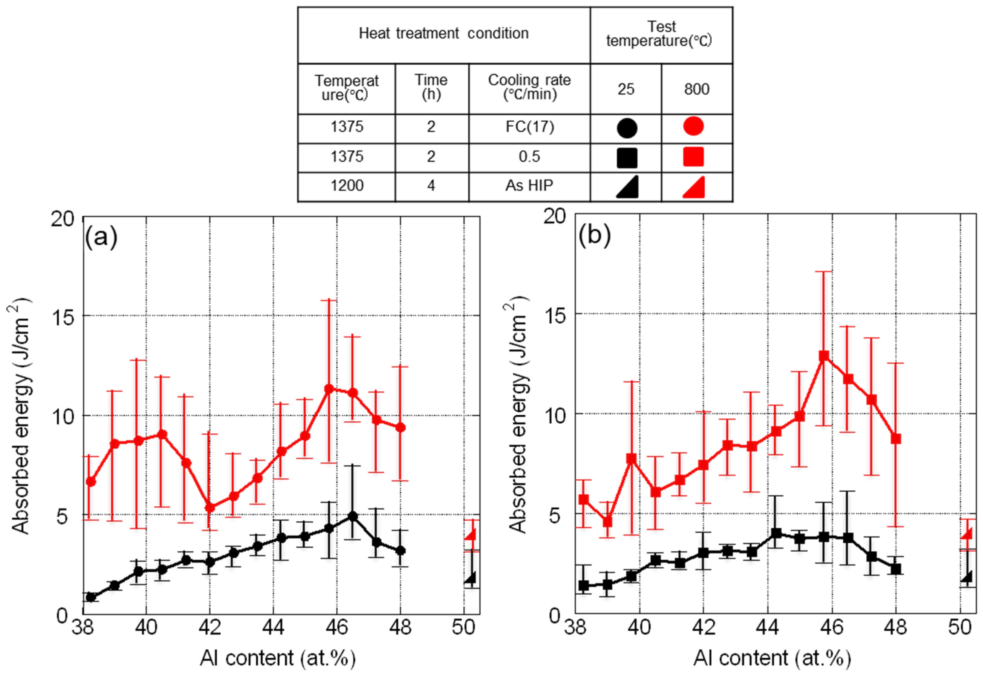
Figure 3 depicts the relationship between Al content and Charpy absorbed energies at 25 and 800 °C for FC and cooling at 0.5 °C/min following heat treatment at 1375 °C. Note that the 50.25 Al alloy is as-HIPed at 1200 °C. Overall, the absorbed energy at 800 °C is considerably higher than that at 25 °C. This is believed to be because the material exhibits a certain degree of ductility while maintaining a particular level of strength at 800 °C. Irrespective of the test temperature, the 45.75 Al alloy exhibits the highest absorbed energy for both cooling rates. Impact resistance is significantly lower on the low-Al side. Specifically, under FC conditions, the absorbed energies of the alloys with an Al content of 42 or less are approximately half or lower than that of the 45.75 Al alloy at 25 °C, and approximately two-thirds or lower at 800 °C, respectively. Additionally, at a cooling rate of 0.5 °C/min, the absorbed energies of the alloys with an Al content of 42 or lower are less than two-thirds that of the 45.75 Al alloy at 25 °C and less than half at 800 °C. That is, the impact resistances of low-Al TiAl alloys with α2 phase-dominant lamellar structures were revealed to be substantially lower than those of conventional (γ-dominant) TiAl alloys.
Figure 3.
Relationship between Al content and Charpy absorbed energy at 25 and 800 °C for Ti-xAl alloys heat-treated under different conditions: (a) heating at 1375 °C for 2 h and furnace cooling and (b) heating at 1375 °C for 2 h and cooling at 0.5 °C/min.
On the other hand, the impact resistances of both γ and α2 single-phase alloys, positioned at opposite extremities of the figure, are the lowest observed. This suggests that although the impact resistance of each phase constituting the TiAl alloy is low, the combination of both phases as a lamellar structure demonstrates improved impact resistance. A comparison of the absorbed energies of the two single-phase alloys reveals that the difference is small at 25 °C, whereas at 800 °C, the α2 phase clearly exhibits a higher absorbed energy than the γ phase. Despite containing a greater proportion of the α2 phase, which exhibits higher impact resistance than the γ phase at 800 °C, the low-Al TiAl alloy displays lower impact resistance than the high-Al alloy. These results suggest that the impact resistances of TiAl alloys cannot be explained by the mixing law of corresponding constituent phase ratios; rather, their structures (specifically α2 phase spacings) exert a considerable influence on the impact resistance.
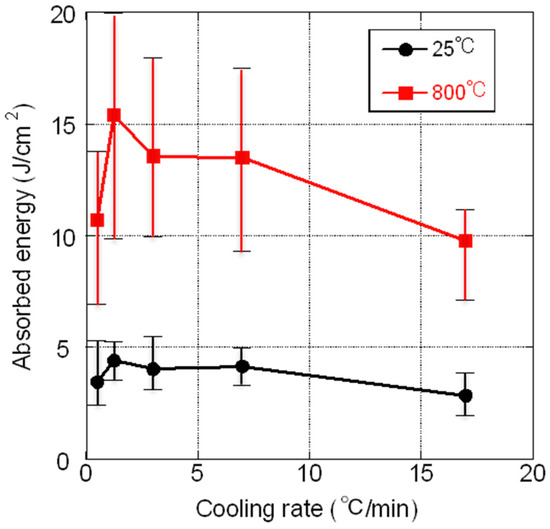
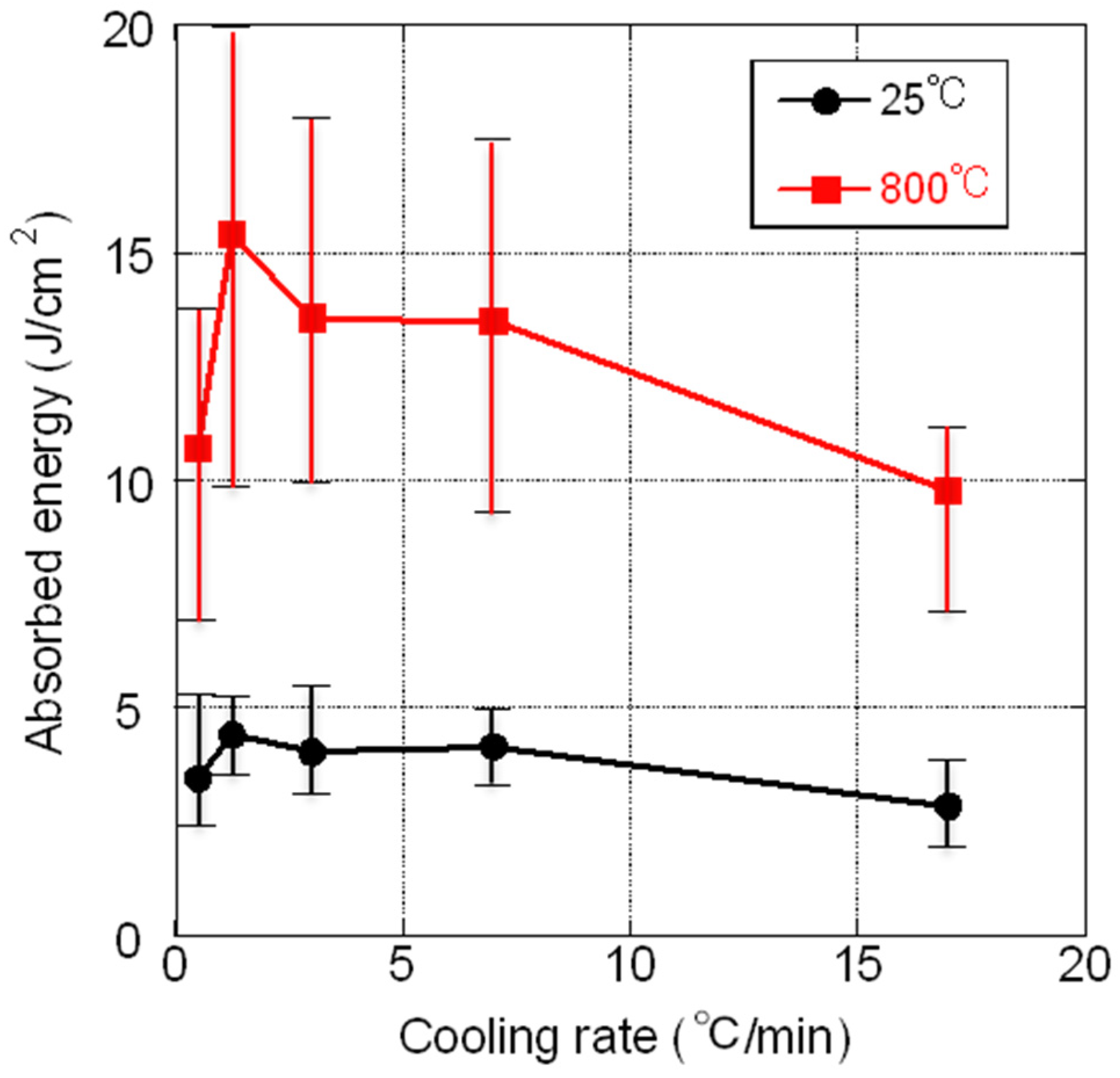
Figure 4 shows the relationship between the cooling rate following holding the specimen at 1375 °C and the absorbed energies at 25 and 800 °C for the 47.25 Al alloys. At both temperatures, the absorbed energies are highest at a cooling rate of 1.25 °C/min, decreasing at both lower and higher cooling rates. As abovementioned (Figure 2), the α2 phase spacing increases with a decrease in the cooling rate. This finding suggests that a cooling rate of 1.25 °C/min produces an α2 phase spacing conducive to enhanced impact resistance.
Figure 4.
Relationship between cooling rate and Charpy absorbed energy at 25 and 800 °C for Ti-47.25Al.
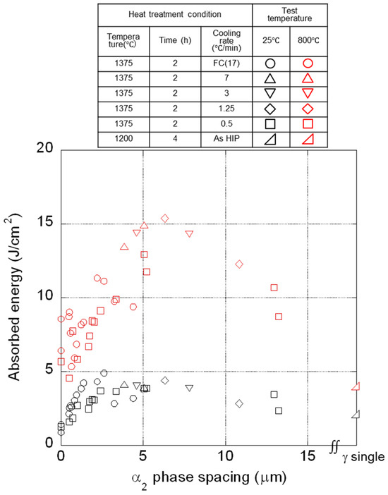
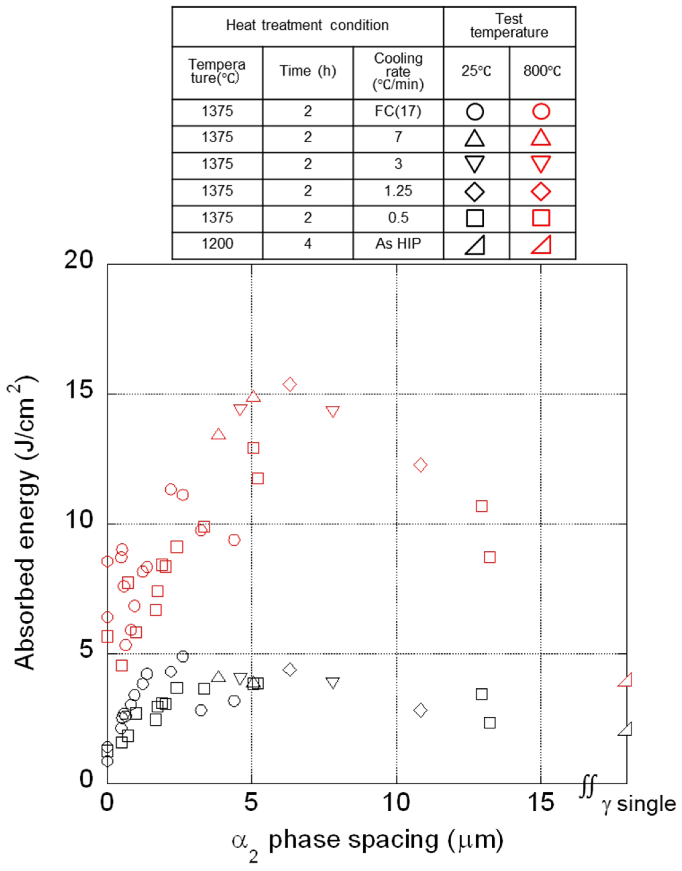
As mentioned earlier, the α2 phase spacing significantly affects impact resistance. Figure 5 depicts the relationship between α2 phase spacing and average absorbed energies at 25 and 800 °C for all alloys. At 25 °C, the absorbed energy is inherently low, obscuring any discernible trend; nevertheless, extremely small or large α2 phase spacings correspond to low absorbed energies. In contrast, a clear trend is observed in the 800 °C test: the absorbed energy peaks at an α2 phase spacing of approximately 6 μm.
Figure 5.
Relationship between α2 phase spacing and mean Charpy absorbed energy at 25 and 800 °C for Ti-xAl alloys heat-treated under different conditions.
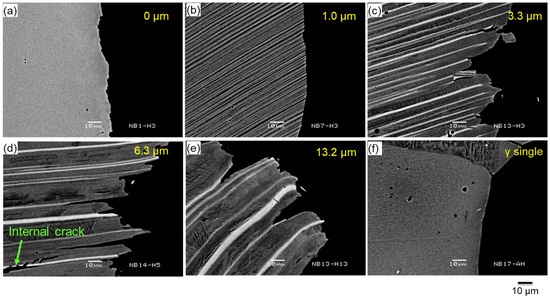
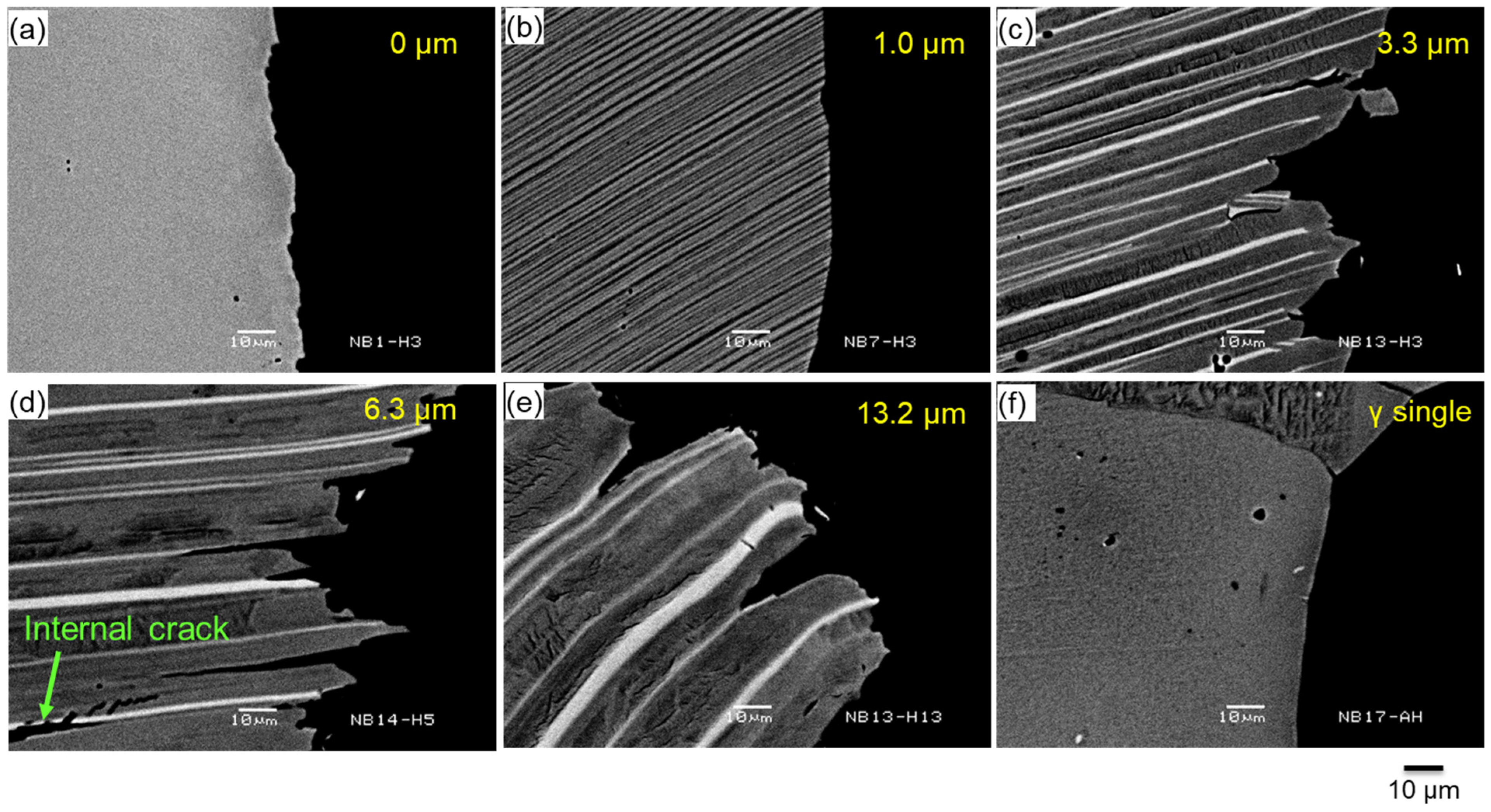
Figure 6 shows the backscattered electron images depicting the cross-sectional microstructure near the fracture surface of the Charpy test specimen tested at 800 °C. The images correspond to α2 phase spacings of 0 (α2 single phase), 1.0, 3.3, 6.3, and 13.2 μm and the γ single-phase alloy. In all cases, the right edge corresponds to the fracture surface. The fracture surface of the γ single-phase alloy is smooth with almost no branched cracks. This indicates easy crack propagation, resulting in the lowest absorbed energy. Although the α2 single-phase alloy exhibits similar characteristics, it features some surface irregularities. For low-Al alloys with α2 phase spacings of 1.0 μm, the fracture surfaces are nearly linear with few branched cracks. In contrast, branched cracks are detected along the γ-phase interior and α2/γ interface for the alloys with α2 phase spacings of 3.3, 6.3, or 13.2 μm. The highest number of branched cracks and internal cracks occurs for the alloy with an α2 phase spacing of 6.3 μm.
Figure 6.
Backscattered electron images depicting the cross-sectional microstructures near the fracture zones of Charpy test specimens investigated at 800 °C for representative Ti-xAl alloys with different Al contents heat-treated under different conditions: (a) Ti-38.25Al, heating at 1375 °C for 2 h (FC); (b) Ti-40.5Al, heating at 1375 °C for 2 h (cooling at 0.5 °C/min); (c) Ti-45.0Al, heating at 1375 °C for 2 h (cooling at 0.5 °C/min); (d) Ti-47.25Al, heating at 1375 °C for 2 h (cooling at 1.25 °C/min); (e) Ti-48.0Al, heating at 1375 °C for 2 h (cooling at 0.5 °C/min); and (f) Ti-50.25Al, heating at 1200 °C for 4 h (as-HIP).
According to Nonaka et al. [27], crack deflection at the interfaces between phases within lamellar structures causes crack propagation to follow a zigzag path. This alteration in the stress field at the crack tip is believed to act as resistance to further propagation. Based on observations of this study (Figure 6), the absorbed energy at 800 °C is thought to be contributed by two effects: the deflection of primary cracks by the α2/γ phase interface, and stress relaxation due to plastic deformation of the γ phase sandwiched between α2 phases. In low-Al alloys, the very small α2 phase spacing resulted in extremely narrow γ-phase thickness. Furthermore, since the γ phase was constrained by the α2 phase, no plastic deformation of the γ phase occurred, leading to reduced absorbed energy. Furthermore, when the α2 phase spacing becomes very large, the number of interfaces themselves decreases. Consequently, the interface effect diminishes, leading to reduced absorbed energy. The optimal impact resistance observed at an α2 phase spacing of 6.3 μm is estimated to result from these two effects working in a well-balanced manner.
3.2. Effects of Reduced Al Content in Forged Alloys
3.2.1. Forgeability
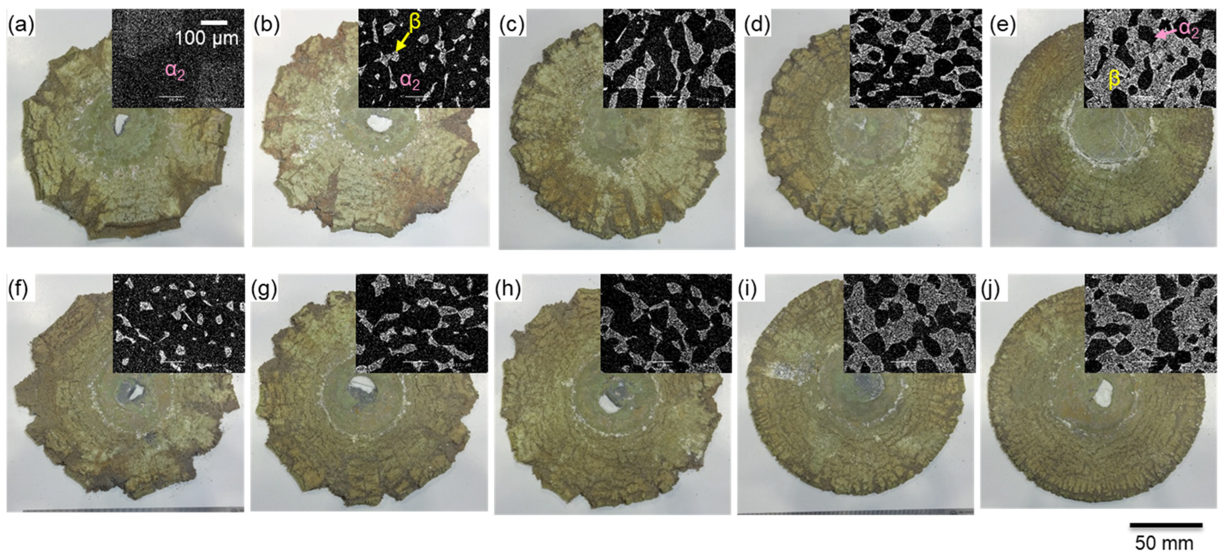
Figure 7 shows the photos of the forged materials from two compositional series (with increasing Cr content and decreasing Al content). This figure also depicts backscattered electron images of samples water-quenched from 1330 °C for each composition. Table 1 presents the β phase area ratios for all water-quenched samples. A clear relationship exists between forgeability and β phase area ratio for each alloy. With a decrease in the β phase content, forgeability deteriorates and more cracks appear.
Figure 7.
Photos of the hot-forged material at 1330 °C and backscattered electron images showing the microstructures of the water-quenched samples from 1330 °C for different Ti-xAl-yCr-0.2B alloys: (a) Ti-43.5Al-1.5Cr-0.2B, (b) Ti-43.5Al-2.0Cr-0.2B, (c) Ti-43.5Al-2.5Cr-0.2B, (d) Ti-43.5Al-3.0Cr-0.2B, (e) Ti-43.5Al-3.5Cr-0.2B, (f) Ti-43.0-Al-1.5Cr-0.2B, (g) Ti-42.5Al-1.5Cr-0.2B, (h) Ti-42.0Al-1.5Cr-0.2B, (i) Ti-41.5Al-1.5Cr-0.2B, and (j) Ti-41.0Al-1.5Cr-0.2B.
Table 1.
Area ratios of the β phase in different Ti-xAl-yCr-0.2B water-quenched alloys from 1330 °C.
Among the alloys in the series with increasing Cr content, only Ti-43.5Al-3.5Cr-0.2B exhibited no cracking. This suggests that 43.5 Al requires the addition of 3.5% or more of the β-stabilizing element, Cr, to demonstrate forgeability at 1330 °C. In contrast, no cracking was observed for the Ti-41.5 and 41.0 Al-1.5 Cr-0.2 B alloys in the series with decreasing Al content. These results confirm the initial expectation that forgeability can be retained even when additional levels of β-stabilizing elements are reduced by lowering the Al concentration.
3.2.2. Microstructure and Material Properties
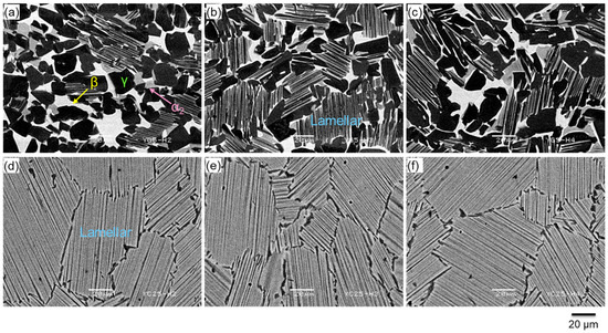
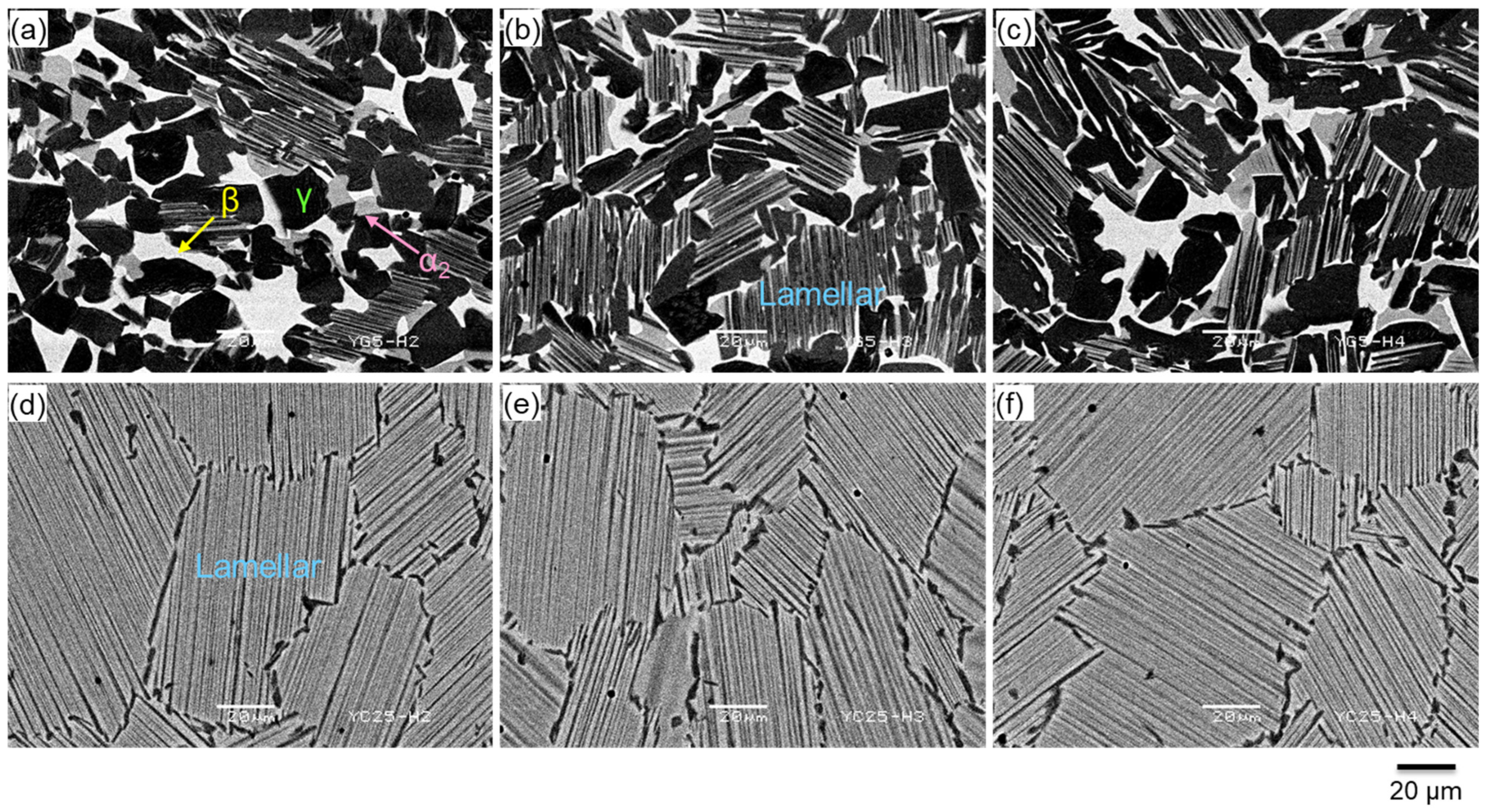
Figure 8 shows the microstructures of the samples of the two alloys Ti-43.5Al-3.5Cr-0.2B and Ti-41.0Al-1.5Cr-0.2B, which demonstrated excellent forgeabilities (Figure 7), and held at 1200, 1240, and 1280 °C for 5 h, followed by cooling at 5 °C/min. In the case of Ti-43.5Al-3.5Cr-0.2B, although the ratio of each structure and phase varies with heat-treatment temperature, all samples exhibit a lamellar + γ + β structure. A large amount of β phase is present, and it is clear that this phase cannot be removed by heat treatment at this composition. Contrarily, Ti-41.0Al-1.5Cr-0.2B demonstrates consistent behavior regardless of the heat-treatment temperature. It forms a fully lamellar structure with a high α2 phase ratio and narrow α2 phase spacing. Furthermore, the introduction of B was verified to suppress the formation of excessively coarse lamellar colonies. At 1240 °C (the β phase volume was minimal in Ti-43.5Al-3.5Cr-0.2B), both forged materials were heat-treated under the conditions of holding for 5 h followed by cooling at 5 °C/min, and the properties of the resulting materials were evaluated. Specifically, the properties of the two alloys with microstructures depicted in Figure 8b,e were assessed.
Figure 8.
Backscattered electron images depicting the microstructures for (a–c) Ti-43.5Al-3.5Cr-0.2B and (d–f) Ti-41.0Al-1.5Cr-0.2B heat-treated under different conditions: (a,d) heating at 1200 °C for 5 h and cooling at 5 °C/min; (b,e) heating at 1240 °C for 5 h and cooling at 5 °C/min; and (c,f) heating at 1280 °C for 5 h and cooling at 5 °C/min.
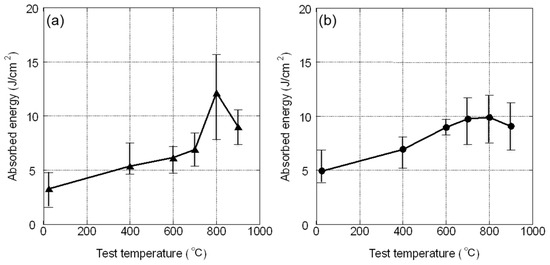
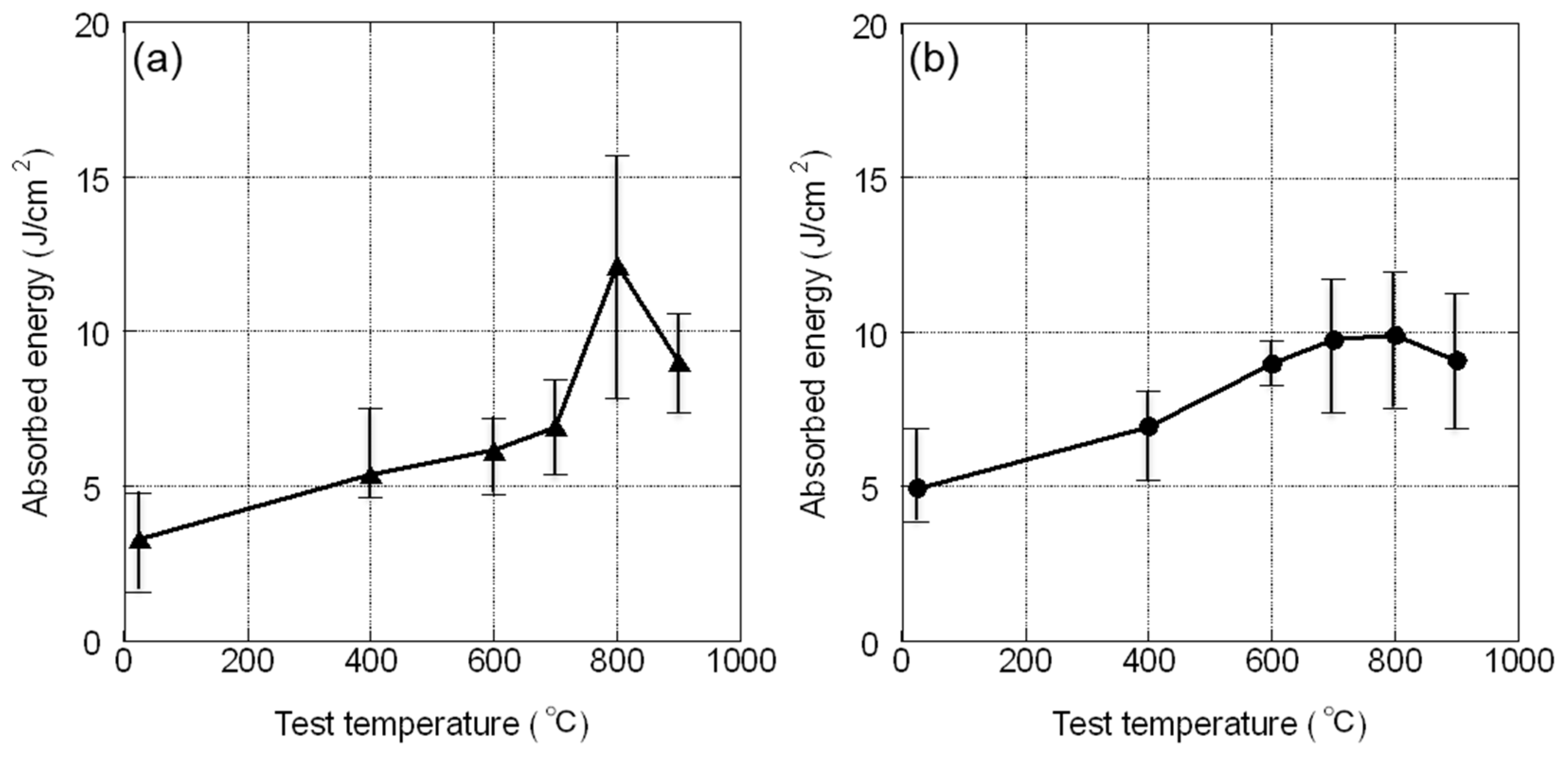
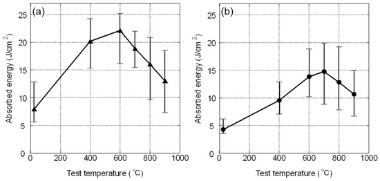
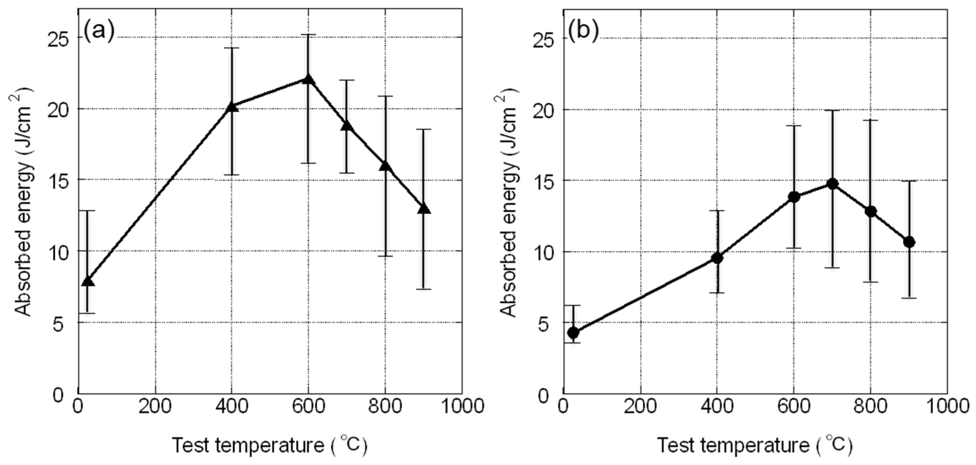
Figure 9 shows the absorbed energies obtained from Charpy impact tests conducted at 25, 400, 600, 700, 800, and 900 °C for two alloys. Up to 700 °C, Ti-41.0Al-1.5Cr-0.2B exhibits higher absorbed energy than Ti-43.5Al-3.5Cr-0.2B; however, this trend reverses at 800 °C. This reversal is possibly due to softening of the β phase in Ti-43.5Al-3.5Cr-0.2B. At 900 °C, both alloys exhibit comparable absorbed energies; this is probably because softening of the β phase progressed further, reducing strength. Superior impact resistance of Ti-41.0Al-1.5Cr-0.2B relative to Ti-43.5Al-3.5Cr-0.2B below 700 °C is possibly because Ti-41.0Al-1.5Cr-0.2B lacks the β phase, which is detrimental to impact resistance at medium and low temperatures.
Figure 9.
Relationship between test temperature and Charpy absorbed energy for (a) Ti-43.5Al-3.5Cr-0.2B and (b) Ti-41.0Al-1.5Cr-0.2B hot-forged at 1330 °C and heat-treated at 1240 °C for 5 h followed by cooling at 5 °C/min.
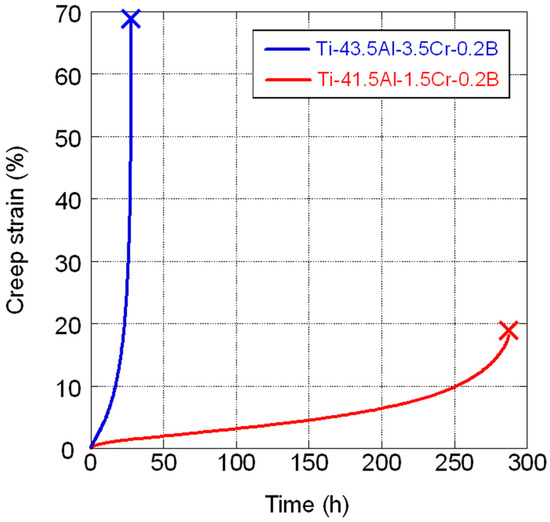
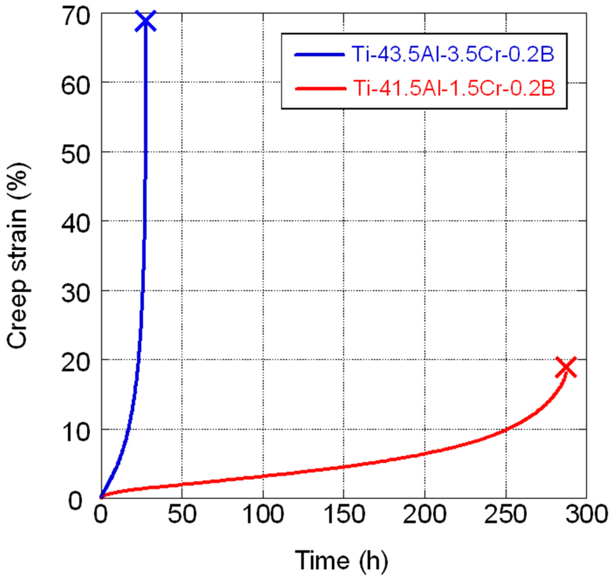
Figure 10 depicts the creep curve obtained from the creep test performed at 775 °C under 200 MPa. The creep life of Ti-41.0Al-1.5Cr-0.2B is clearly longer than that of Ti-43.5Al-3.5Cr-0.2B. This difference is due to the absence of the detrimental β phase in Ti-41.0Al-1.5Cr-0.2B, which reduces creep strength, and the presence of a certain amount of this phase in Ti-43.5Al-3.5Cr-0.2B (Figure 8).
Figure 10.
Creep curves at 775 °C under 200 MPa for Ti-43.5Al-3.5Cr-0.2B and Ti-41.0Al-1.5Cr-0.2B hot-forged at 1330 °C and heat-treated at 1240 °C for 5 h followed by cooling at 5 °C/min.
Based on the abovementioned evaluation, it was confirmed that reducing the Al content of forged TiAl alloys allows forgeability retention even with reduced additions of β-stabilizing elements, while simultaneously enabling the elimination of the β phase through heat treatment (Figure 7 and Figure 8). Moreover, this resulted in enhanced impact resistance below 700 °C and improved creep strength (Figure 9 and Figure 10). That is, as initially expected, a reduction in the Al contents of forged TiAl alloys resulted in corresponding improvements in performance. This is due to the significantly inferior properties of the β phase. Forged low-Al alloys demonstrate fully lamellar structures with high α2 phase ratios and small α2 phase spacings. As stated in Section 3.1, this microstructure leads to lower impact resistance than those of high-Al alloys dominated by the γ phase. Nevertheless, as the β phase present in conventional forged TiAl alloys exerts further detrimental effects, the reduction in Al- and β-stabilizing element contents can be speculated to have caused some improvements in the properties of the forged alloy.
3.3. Influence of Reduced Al Content in Cast TiAl4822
Ti-47.0Al-2.0Nb-2.0Cr exhibited a γ + lamellar structure with an α2 phase ratio of 0.17 and an α2 phase spacing of 1.9 μm within the lamellar structure. On the other hand, Ti-42.0Al-2.0Nb-1.0Cr exhibite a fully lamellar structure with an α2 phase ratio of 0.65 and an α2 phase spacing of 1.0 μm. Figure 11 shows the absorbed energies acquired from Charpy impact tests conducted on the two alloys at temperatures of 25, 400, 600, 700, 800, and 900 °C. At all temperatures, Ti-47.0Al-2.0Nb-2.0Cr exhibits higher absorbed energy than Ti-42.0Al-2.0Nb-1.0Cr. As established in Section 3.1, the impact resistances of low-Al TiAl alloys are inherently lower, owing to the narrower α2 phase spacings (Figure 3). Therefore, even for cast TiAl4822, the impact resistances are lower than those of high-Al TiAl alloys, which are dominated by the γ phase and demonstrate wider α2 phase spacings.
Figure 11.
Relationship between test temperature and Charpy absorbed energy for (a) Ti-47.0Al-2.0Nb-2.0Cr and (b) Ti-42.0Al-2.0Nb-1.0Cr HIPed at 1200 °C for 4 h under 186 MPa.
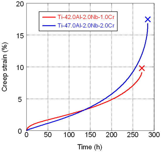
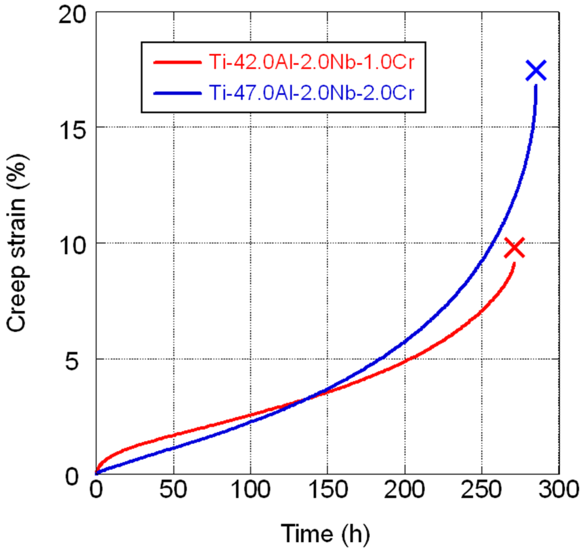
Figure 12 depicts the creep curves for both alloys at 775 °C under 200 MPa. The creep lives of both alloys are nearly equivalent. Figure 13 shows the microstructure near the creep fracture zone for both alloys. Ti-47.0Al-2.0Nb-2.0Cr exhibits a γ + lamellar structure, and numerous fine creep voids are noticed in the γ phase. In contrast, Ti-42.0Al-2.0Nb-1.0Cr demonstrates a fully lamellar structure, which is characteristic of low-Al TiAl alloys. It features a high α2 phase ratio and a narrow α2 phase spacing (1.0 μm), and long linear creep voids are concentrated in the γ phase at lamellar colony boundaries. Additionally, areas without creep voids exhibit signs of partial dynamic recrystallization.
Figure 12.
Creep curves at 775 °C under 200 MPa for Ti-47.0Al-2.0Nb-2.0Cr and Ti-42.0Al-2.0Nb-1.0Cr HIPed at 1200 °C for 4 h under 186 MPa.
Figure 13.
Backscattered electron images showing the cross-sectional microstructures near the fracture zones of the creep test specimens examined at 775 °C under 200 MPa: (a) Ti-47.0Al-2.0Nb-2.0Cr and (b) Ti-42.0Al-2.0Nb-1.0Cr.
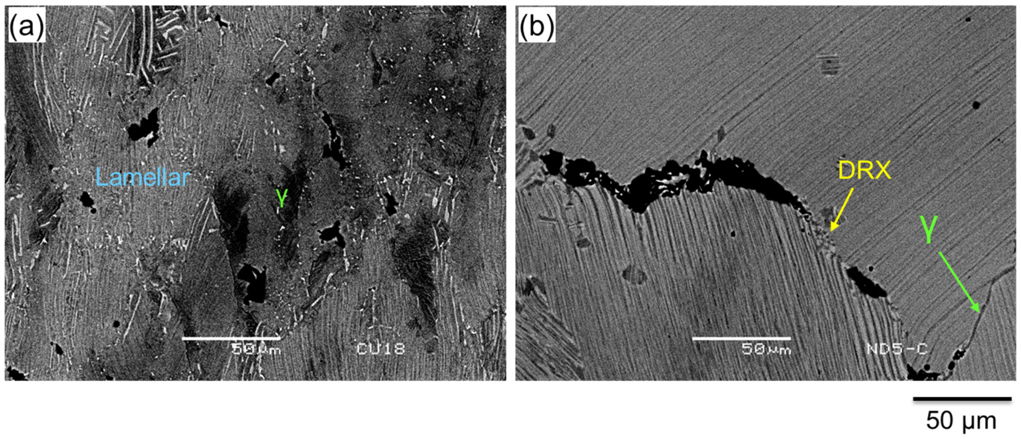
Maruyama et al. [7] investigated the creep properties of Ti-42.0Al with a fully lamellar structure. They performed compression creep tests on samples with altered lamellar spacings due to different cooling rates during heat treatment. Their findings suggest that the reduction in lamellar spacing enhances creep strength. This is different from the findings of the present study. Disparity in creep testing methods may account for this difference. They observed the microstructure after 4% compression creep deformation and detected no creep voids at the lamellar colony boundaries. Instead, they observed numerous fine grains formed through dynamic recrystallization at this boundary. However, as tensile creep tests were conducted herein, locally excessive tensile strain was considered to occur in the weak γ phase present at the lamellar colony boundaries, leading to long linear creep voids (Figure 13). In other words, although the fully lamellar structure with small α2 phase spacing in low-Al TiAl4822 examined in this study may have exhibited high creep strength in the lamellar colonies itself, the existence of a low-strength γ phase at the lamellar colony boundaries is believed to have caused short-term fracture. Hence, it has been confirmed that reducing the Al content in cast TiAl4822 is not very effective for enhancing the properties required for jet engine blades.
4. Conclusions
To evaluate the practicality of low-Al TiAl alloys with fully lamellar structures dominated by the α2 phase as jet engine blade material, at first, the effects of α2 phase ratio and spacing on impact resistances (the most essential properties of TiAl alloys used for jet engine blades) at 25 and 800 °C were examined using Charpy impact tests; furthermore, impact resistances of low-Al alloys were compared with those of high-Al alloys. Subsequently, the effect of reduced Al content on the properties required for jet engine blades was investigated in forged Ti-Al-Cr-B alloys and cast TiAl4822. The results revealed the following trends:
- The α2 single phase exhibits higher impact resistance at 800 °C than the γ single phase. Nevertheless, in lamellar structures, the α2 phase spacing exerts a more considerable effect on impact resistance than the ratio of the two phases present. The best results were obtained at a relatively coarse spacing of approximately 6 μm (high-Al alloy). Low-Al TiAl alloys can only form extremely small α2 phase spacings, resulting in low impact resistances—ranging from less than half to two-thirds those of high-Al TiAl alloys.
- In the cases of forged alloys, the reduction in Al content facilitated forgeability retention even with reduced amounts of β-stabilizing elements, and the β phase could be eliminated through heat treatment. Consequently, impact resistance below 700 °C and creep strength improved in comparison to those of conventional forged TiAl alloys containing β phase.
- Impact resistance of low-Al cast TiAl4822 was low. Furthermore, its creep strength did not improve as expected. This was attributed to the preferential deformation of the low-strength γ phase present at lamellar colony boundaries.
Funding
This research was funded by the Japan Science and Technology Agency (grant number AS0216001).
Data Availability Statement
The original contributions presented in this study are included in the article. Further inquiries can be directed to the corresponding author.
Conflicts of Interest
The author declares no conflicts of interest.
Abbreviations
The following abbreviation is used in this manuscript:
| HIP | Hot Isostatic Pressing |
References
- Bartolotta, P.; Barrett, J.; Kelly, T.; Smashey, R. The use of cast Ti−48Al−2Cr−2Nb in jet engines. JOM 1997, 49, 48–50. [Google Scholar] [CrossRef] [Scilit]
- Bewlay, B.P.; Nag, S.; Suzuki, A.; Weimer, M.J. TiAl alloys in commercial aircraft engines. Mater. High. Temp. 2016, 33, 549–559. [Google Scholar] [CrossRef] [Scilit]
- Perrut, M.; Caron, P.; Thomas, M.; Couret, A. High temperature materials for aerospace applications: Ni-based superalloys and γ-TiAl alloys. Comptes Rendus Phys. 2018, 19, 657–671. [Google Scholar] [CrossRef] [Scilit]
- Clemens, H.; Mayer, S. Design, processing, microstructure, properties, and applications of advanced intermetallic TiAl alloys. Adv. Eng. Mater. 2013, 15, 191–215. [Google Scholar] [CrossRef] [Scilit]
- Hemmerdinger, J. FAA Orders PW1100G Low-Pressure Turbine Blade Replacement. FlightGlobal.com. Available online: https://www.flightglobal.com/engines/faa-orders-pw1100g-low-pressure-turbine-blade-replacement/135575.article (accessed on 2 February 2026).
- Tetsui, T. Impact resistance of commercially applied TiAl alloys and simple-composition TiAl alloys at various temperatures. Metals 2022, 12, 2003. [Google Scholar] [CrossRef] [Scilit]
- Maruyama, K.; Yamamoto, R.; Nakakuki, H.; Fujitsuna, N. Effects of lamellar spacing, volume fraction and grain size on creep strength of fully lamellar TiAl alloys. Mater. Sci. Eng. A 1997, 239–240, 419–428. [Google Scholar] [CrossRef] [Scilit]
- Lapin, J.; Kamyshnykova, K.; Klimova, A. Comparative study of microstructure and mechanical properties of two TiAl-based alloys reinforced with carbide particles. Molecules 2020, 25, 3423. [Google Scholar] [CrossRef] [Scilit]
- Niinobe, K.; Kitagawa, H. Microstructural control of binary Ti-41Al and Ti-45Al alloys by heat treatment. NETSUSHORI 2024, 64, 47–52. [Google Scholar] [CrossRef]
- Beddoes, J.; Wallace, W.; Zhao, L. Current understanding of creep behaviour of near γ-titanium aluminides. Int. Mater. Rev. 1995, 40, 197–217. [Google Scholar] [CrossRef] [Scilit]
- Zhang, S.; Tian, S.; Li, G.; Tian, N.; Jin, F.; Yu, H.; Lv, X.; Wang, G.; Li, D. Creep behavior and effect factors of a TiAl–Nb alloy at high temperature. Prog. Nat. Sci. Mater. Int. 2021, 31, 477–485. [Google Scholar] [CrossRef] [Scilit]
- Yamaguchi, M.; Inui, H.; Yokoshima, S.; Kishida, K.; Johnson, D.R. Recent progress in our understanding of deformation and fracture of two-phase and single-phase TiAl alloys. Mater. Sci. Eng. A 1996, 213, 25–31. [Google Scholar] [CrossRef] [Scilit]
- Zhu, B.; Xue, X.; Kou, H.; Li, X.; Li, J. Effect of microstructure on the fracture toughness of multi-phase high Nb-containing TiAl alloys. Intermetallics 2018, 100, 142–150. [Google Scholar] [CrossRef] [Scilit]
- Tetsui, T.; Mizuta, K. Detrimental effects of βo-phase on practical properties of TiAl alloys. Metals 2024, 14, 908. [Google Scholar] [CrossRef] [Scilit]
- Molénat, G.; Galy, B.; Musi, M.; Toualbi, L.; Thomas, M.; Clemens, H.; Monchoux, J.-P.; Couret, A. Plasticity and brittleness of the ordered βo phase in a TNM-TiAl alloy. Intermetallics 2022, 151, 107653. [Google Scholar] [CrossRef] [Scilit]
- Sallot, P.; Monchoux, J.P.; Joulié, S.; Couret, A.; Thomas, M. Impact of β-phase in TiAl alloys on mechanical properties after high temperature air exposure. Intermetallics 2020, 119, 106729. [Google Scholar] [CrossRef] [Scilit]
- Nakatani, M.; Shimono, A.; Yamamoto, T.; Hiyoshi, N.; Itoh, T. Low cycle fatigue properties in forged TiAl alloy Ti-43Al-5V-4Nb with triplex microstructure. J. Soc. Mater. Sci. Jpn. 2021, 70, 111–117. [Google Scholar] [CrossRef] [Scilit]
- Wang, J.G.; Nieh, T.G. Creep of a beta phase-containing TiAl alloy. Intermetallics 2000, 8, 737–748. [Google Scholar] [CrossRef] [Scilit]
- Nishikiori, S.; Takahashi, S.; Satou, S.; Tanaka, T.; Matsuo, T. Microstructure and creep strength of fully-lamellar TiAl alloys containing beta-phase. Mater. Sci. Eng. A 2002, 329–331, 802–809. [Google Scholar] [CrossRef] [Scilit]
- Yang, G.; Xu, X.; Sun, T.; Xu, S.; Gui, W.; Zeng, J.; Mu, Y.; Liang, Y.; Lin, J. A refined fully lamellar TiAl alloy extruded at α-phase region: Microstructure and mechanical properties. Mater. Sci. Eng. A 2023, 888, 145804. [Google Scholar] [CrossRef] [Scilit]
- Li, X.; Qian, K.; Shu, L.; Zhang, M.; Chen, B.; Liu, K. Tailored fully lamellar microstructure of a newly developed Mn-Containing β-solidifying γ-TiAl alloys rolled bar. JOM 2022, 74, 2985–2995. [Google Scholar] [CrossRef] [Scilit]
- Shaaban, A.; Signori, L.J.; Nakashima, H.; Takeyama, M. Effects of the addition of transition metals on phase equilibria and phase transformations in TiAl systems in between 1473 and 1073 K. J. Alloys Compd. 2021, 878, 160392. [Google Scholar] [CrossRef] [Scilit]
- Kim, Y.-W.; Kim, S.-L. Advances in Gammalloy materials–processes–application technology: Successes, dilemmas, and future. JOM 2018, 70, 553–560. [Google Scholar] [CrossRef] [Scilit]
- Chan, K.S.; Kim, Y.-W. Effects of lamellae spacing and colony size on the fracture resistance of a fully-lamellar TiAl alloy. Acta Metall. Mater. 1995, 43, 439–451. [Google Scholar] [CrossRef] [Scilit]
- Ohnuma, I.; Fujita, Y.; Mitsui, H.; Ishikawa, K.; Kainuma, R.; Ishida, K. Phase Equilibria in the Ti–Al binary system. Acta Mater. 2000, 48, 3113–3123. [Google Scholar] [CrossRef] [Scilit]
- Kawaura, H.; Nishino, K.; Saito, T. Effects of alloying elements on foreign object damage resistance of cast-TiAl base alloys. J. Jpn. Inst. Met. Mater. 2002, 66, 451–458. [Google Scholar] [CrossRef] [Scilit]
- Nonaka, K.; Kawabata, T.; Nakajima, H.; Tanosaki, K.; Echigoya, J. Deformation and fracture of TiAl alloys with a coarsely spaced lamellar structure on compression test at room temperature. J. Jpn. Inst. Met. Mater. 2001, 65, 1029–1037. [Google Scholar] [CrossRef] [Scilit]

Disclaimer/Publisher’s Note: The statements, opinions and data contained in all publications are solely those of the individual author(s) and contributor(s) and not of MDPI and/or the editor(s). MDPI and/or the editor(s) disclaim responsibility for any injury to people or property resulting from any ideas, methods, instructions or products referred to in the content. |
© 2026 by the author. Licensee MDPI, Basel, Switzerland. This article is an open access article distributed under the terms and conditions of the Creative Commons Attribution (CC BY) license.